american national standard for ansi/iiar 2-2008, (includes...
TRANSCRIPT

Approved by the American National Standards InstituteJune 3, 2008
Supersedes ANSI/IIAR 2-1999
Addendum A Approved by the American National Standards Institute, August 4, 2010
Equipment, Design, and Installation of Closed-Circuit Ammonia Mechanical Refrigerating Systems
American National Standard For ANSI/IIAR 2-2008, (Includes Addendum A)

Notes on the Standard Text
Metric Policy
The IIAR metric policy for ANSI standards, bulletins and all IIAR publications is to use the common engineering “inch-pound” (IP) unit system as the primary unit of measure, and the International System of Units (SI), as defined in United States National Institute of Standards and Technology Special Publication 330 “The International System of Units,” for secondary units.
Informative/Normative Elements
This standard includes both Normative (required) and Informative (advisory) language. The body of the standard and labeled appendices are Normative. The foreword, notes, and any appendices labeled Informative are non-mandatory. Informative material shall never be regarded as a requirement.
Notice
The information contained in this Standard has been obtained from sources believed to be reliable. However, it should not be assumed that all acceptable methods or procedures are contained in this document, or that additional measures may not be required under certain circumstances or conditions.
The International Institute of Ammonia Refrigeration makes no warranty or representation and assumes no liability or responsibility in connection with any information contained in this document.
While the Institute recommends use of and reference to this document by private industry, government agencies and others, this publication is intended to be voluntary and not binding.
The Institute does not “approve” or “endorse” any products, services or methods. This document shall not be used or referenced in any way that would imply such approval or endorsement.
Note that the various codes and regulations referenced in this document may be amended from time to time and it should not be assumed that the versions referenced herein are the most current versions of such codes and regulations. Please consult the appropriate regulatory authorities for the most up-to-date versions.
The Standard is subject to periodic review. It may be changed, revised or withdrawn without notice and is only current as of its publication date. Up-to-date information may be received by calling or writing IIAR.
Note that the various codes and regulations referenced in the Standard may be amended from time to time and it should not be assumed that the versions referenced in the Standard are the most current versions of such codes and regulations. Please consult the appropriate regulatory authorities for the most up-to-date versions.
Copyright
This document may not, in whole or in part, be reproduced, copied or disseminated, entered into or stored in a computer database or retrieval system, or otherwise utilized without the prior written consent of the IIAR.
Copyright © 2010 byINTERNATIONAL INSTITUTE OF AMMONIA REFRIGERATION
All Rights Reserved

Copyright © 2010 International Institute of Ammonia Refrigeration. All Rights Reserved. i
ANSI/IIAR 2-2008Equipment, Design, and Installation of Closed-Circuit Ammonia Mechanical Refrigerating Systems
Foreword (Informative)
This document is intended to serve as a standard for equipment, design and installation of closed-circuit ammonia refrigerating systems. Additional requirements may be necessary because of particular circumstances, project specifications or other jurisdictional considerations. Note that this standard does not constitute a comprehensive detailed technical design manual and should not be used as such.
Experience shows that ammonia is very difficult to ignite and is very stable under normal conditions. The ammonia concentration must be about 1000 times above that considered hazardous to humans before flammability becomes a concern.
Ammonia’s strong odor alerts those nearby to its presence at levels well below those that present a hazard. This “self-alarming” odor is so strong that a person is unlikely to voluntarily remain in an area where ammonia concentrations are hazardous.
The principal hazard to persons is ammonia vapor, since exposure occurs more readily by inhalation than by other routes. As with any hazardous vapor, adequate ventilation is the key to effective control.
Ammonia in vapor form is lighter than air. It rises and diffuses simultaneously when released into the atmosphere. It is biodegradable, and when released it combines readily with water and/or carbon dioxide to form relatively harmless compounds. Ammonia may also neutralize acidic pollutants in the atmosphere. Additional information regarding the properties of ammonia is published in the IIAR Ammonia Data Book.
This standard was first issued in March of 1974 by the International Institute of Ammonia Refrigeration (IIAR) as IIAR 74-2. The standard was intended to be a reference document covering the minimum requirements for specific aspects of industrial closed-circuit ammonia refrigerating systems to supplement existing refrigeration standards issued by other organizations such as ASHRAE, ASME and ANSI. The standard was first approved as an American National Standard by the American National Standards Institute (ANSI) in March 1978 as ANSI/IIAR 74−2−1978. A revision of the standard, ANSI/IIAR 2−1984 was approved by ANSI in July 1985, as were subsequent revisions in December 1992, August 1999, and June 2008. The most recent revision, ANSI/IIAR 2-2008, received approval from ANSI on June 3, 2008.
The changes in the latest edition, Addendum A, from the previous edition include: • Foreword: updated membership list of the Standards Review Committee • Table of Contents: addition of Appendix “L” • Section 3: definition of Machinery Room • Section 4.17: addition of new normative standard • Section 11.3.3: update of relief piping materials • Section 13: Entire update of Machinery Room Design section • Appendix L: New Appendix; “Machinery Room Signage”

ii Copyright © 2010 International Institute of Ammonia Refrigeration. All Rights Reserved.
ANSI/IIAR 2-2008Equipment, Design, and Installation of Closed-Circuit Ammonia Mechanical Refrigerating Systems
This standard was prepared using the Canvass Method whereby organizations and individuals recognized as having interest in the subject of the standard were contacted prior to the approval of this revision. Consensus was achieved by use of the Canvass Method. It was prepared and approved for submittal to ANSI by the IIAR Standards Review Committee and the IIAR Board of Directors.
ANSI/IIAR 2-2008: Changes for the new edition (Informative)
IIAR 2 has undergone an extensive revision to the 1999 version. Some changes are highlighted here to assist users of this document. Largely the content of the standard has not changed, but it has been reorganized and the sections have been renumbered. The Equipment section has been expanded, and each type of equipment now has its own section. The Installation section content has been split between the Machinery Room Design, System Design, and Testing and Charging sections.
• New sections added requiring users to take into account heat loads from cleaning operations for Shell and Tube Evaporators and Plate Heat Exchangers.
• New compressor equipment identification requirement: minimum rotation speed for proper lubrication.
• New requirements for the manufacture of pressure vessel heads added, including hot forming or stress relieving and minimum corrosion allowance.
• Minimum Pipe Wall Thicknesses modified. • Refrigerant Valves section heavily modified. • Sections added on Pipe Hangers and Supports, Pipe Marking. • Section added on Equipment and Piping Hydrostatic Overpressure Protection. • All headings “Safety” have been changed to “Design” because IIAR 2 is not a safety standard. • Type A and B specified for A106 pipe. • Pressure relief requirements of large vessels modified. • New informative Appendix C Ammonia Characteristics and Properties. • New informative Appendix D Duplicate Nameplates on Pressure Vessels. • New informative Appendix F Pipe Hanger Spacing, Hanger Rod Sizing, and Loading. • New informative Appendix G Hydrostatic Pressure Relief. • New informative Appendix J Stress Corrosion Cracking. • New informative Appendix K Emergency Pressure Control Systems.
At the time of publication of this revision of the standard, the IIAR Standards Review Committee had the following members:
G. Robert Shriver, Chair — EVAPCO, Inc.Dennis R. Carroll — Cimco Refrigeration, Inc.Jim Caylor — Jacobs Carter BurgessRobert J. Czarnecki — Campbell Soup CompanyWayne D. Davis — M & M Refrigeration, Inc.Don Faust — Gartner RefrigerationGregory P. Klidonas — FES Systems, Inc.Thomas A. Leighty — Refrigeration Systems CompanyBob Port — TargetBrian Marriott — York Refrigeration GroupRich Merrill — Retired

Copyright © 2010 International Institute of Ammonia Refrigeration. All Rights Reserved. iii
ANSI/IIAR 2-2008Equipment, Design, and Installation of Closed-Circuit Ammonia Mechanical Refrigerating Systems
Table of Contents
Section 1 Purpose 1
Section 2 Scope 1
Section 3 Definitions 2
Section 4 References 6
Section 5 General Requirements 7
Section 6 Compressors and Refrigerant Pumps 9
Section 7 Condensers 11
Section 8 Evaporators 15
Section 9 Pressure Vessels 19
Section 10 Piping 20
Section 11 Overpressure Protection Devices 23
Section 12 Components and Controls 26
Section 13 Machinery Room Design 28
Section 14 System Design 33
Section 15 Testing and Charging 34
Section 16 Sources of References (Informative) 36
Appendix A (Normative) Allowable Equivalent Length of Discharge Piping 37
Appendix B (Normative) Minimum Values of Design Pressure and Leak Test Pressure — NH3 45
Appendix C (Informative) Ammonia Characteristics and Properties 45
Appendix D (Informative) Duplicate Nameplates on Pressure Vessels 47
Appendix E (Informative) Method for Calculating Discharge Capacity of
Positive Displacement Compressor Pressure Relief Device 47
Appendix F (Informative) Pipe Hanger Spacing, Hanger Rod Sizing, and Loading 49
Appendix G (Informative) Hydrostatic Pressure Relief 50
Appendix H (Informative) Insulation for Refrigeration Systems 56
Appendix I (Informative) Purging 58
Appendix J (Informative) Stress Corrosion Cracking 58
Appendix K (Informative) Emergency Pressure Control Systems 60
Appendix L (Informative) Machinery Room Signage 63


Copyright © 2010 International Institute of Ammonia Refrigeration. All Rights Reserved. 1
ANSI/IIAR 2-2008Equipment, Design, and Installation of Closed-Circuit Ammonia Mechanical Refrigerating Systems
Section 1
Purpose
The purpose of this standard is to provide minimum requirements for equipment, design and installation of closed-circuit ammonia refrigerating systems.
Section 2
Scope
This standard shall apply only to closed-circuit refrigerating systems utilizing ammonia as the refrigerant.
2.1 This standard was written as a guide to the design, manufacture and installation of closed-circuit ammonia refrigerating systems in industrial occupancies and is not intended to supplant existing safety codes.
In cases where the jurisdictional authority has specific code requirements that are more stringent than those herein, that authority shall prevail.
2.2 This standard applies:a. To equipment and systems designed, manufactured and installed subsequent to adoption of this standard;b. To parts or components installed after adoption of this standard.
EXCEPTION:replacements in kind that meet the design intent for the original application.
2.3 This standard does not apply to ammonia absorption refrigerating systems.
2.4 In cases of practical difficulty or unnecessary hardship, with approval by the jurisdictional authority, the use of other devices, materials or methods not included in this standard is permitted provided it is clearly evident that equivalent system performance and safety are thereby obtained.

2 Copyright © 2010 International Institute of Ammonia Refrigeration. All Rights Reserved.
ANSI/IIAR 2-2008Equipment, Design, and Installation of Closed-Circuit Ammonia Mechanical Refrigerating Systems
Section 3
Definitions
Defined terms used in a definition are italicized.
actuator: Mechanism for transmission of movement or force.
air-cooled condenser: A refrigerant condenser in which heat removal is accomplished entirely by heat absorption by the air flowing over condensing surfaces. See also condenser, double-pipe (tube-in-tube) condenser, desuperheater, evaporative condenser, shell-and-tube condenser.
air-cooled desuperheater: That part of the system designed to cool the ammonia refrigerant vapor after it is discharged from the compressor and before it enters the condenser. It is provided with a means of forcing air circulation over the external surface of the desuperheater coil for the heat removal necessary to cool the refrigerant vapor on the inside of the tubes.
air duct: A tube or conduit used for conveying air. (The air passages of self contained systems are not air ducts.)
ammonia: Refrigerant-grade anhydrous ammonia.
approved: Acceptable to the jurisdictional authorities.
approved nationally recognized testing laboratory: A laboratory acceptable to the jurisdictional authorities; that provides uniform testing and examination procedures under established standards; is properly organized, equipped, and qualified for testing; and has a follow up inspection service of the current production of the listed products.
automatic expansion valve: A controlling device which regulates the flow of volatile liquid refrigerant into an evaporator of a closed-circuit ammonia refrigerating system and which is actuated by evaporator pressure.
automatic liquid refrigerant drain valve: See highside float valve.
booster compressor: A compressor for discharging to the suction of a higher-stage compressor. See also compressor, positive displacement compressor.
check valve: A valve allowing fluid flow in one direction only.
closed-circuit ammonia refrigerating system: A refrigerating system using mechanical compression to remove the refrigerant from the low pressure side and to deliver it to the high pressure side of the system.
compressor: A specific machine with or without accessories, for compressing ammonia refrigerant vapor. See also booster compressor, positive displacement compressor.
condenser: That part of a closed-circuit ammonia refrigerating system where refrigerant is liquefied by the removal of heat. See also air-cooled condenser, double-pipe (tube-in-tube) condenser, desuperheater, evaporative condenser, shell-and-tube condenser.
condenser coil: That part of a condenser constructed of pipe or tubing not enclosed in a pressure vessel.
control valve: All valves except shut-off valves.
controlled-pressure receiver: An intermediate pressure receiver used to flash-cool refrigerant and to control the feed pressure. See also pressure vessel.
design pressure: The specified working pressure for a specific part of a closed-circuit ammonia refrigerating system.
desuperheater: A device which provides sensible cooling to the refrigerant vapor.
direct expansion: Evaporator arrangement whereby liquid refrigerant is fed through an expansion valve or device and evaporates completely before leaving as vapor.
double-pipe (tube in tube) condenser/desuperheater: A type of condenser/desuperheater constructed of one or more assemblies of two tubes, one within the other, in which refrigerant vapor is condensed/desuperheated either in the annular space or the inner tube. See also air-cooled condenser, condenser, desuperheater, evaporative condenser, shell-and-tube condenser.

Copyright © 2010 International Institute of Ammonia Refrigeration. All Rights Reserved. 3
ANSI/IIAR 2-2008Equipment, Design, and Installation of Closed-Circuit Ammonia Mechanical Refrigerating Systems
downstream pressure regulator: A control valve which regulates the flow of oil or refrigerant gas or liquid through the device which is actuated toward open by a pressure falling below regulator set point downstream of the valve.
dual pressure relief device: Two pressure relief devices (valves or rupture members) mounted on a three way valve that allows one device to remain active while the other is isolated. See also pressure relief device, pressure relief valve.
evaporative condenser: A condenser that obtains cooling effect by the evaporation of water in an air stream on the external surface of the tubes for the heat removal necessary to liquefy refrigerant vapor on the inside of the tubes. See also air-cooled condenser, double-pipe (tube-in-tube) condenser, desuperheater, condenser, shell-and-tube condenser.
evaporator: That part of a closed-circuit ammonia refrigerating system designed to vaporize liquid refrigerant to produce refrigeration. See also shell-and-tube evaporator.
evaporator coil: That part of an evaporator constructed of pipe or tubing not enclosed in a pressure vessel.
evaporator pressure regulator: A control valve which regulates the flow of primarily gaseous refrigerant from an evaporator section and which is actuated toward open by a pressure above set point upstream of the valve.
exit: A passageway adjacent to the door through which people leave a building.
field test: A test performed in the field to prove system tightness.
forced feed oil lubrication: A lubrication system in which oil is provided by an internal or external mechanical oil pump. This does not include splash type or drip type compressor lubrication systems.
flow regulator: A control valve which regulates the flow of liquid through the device which is actuated by flow rate changes to maintain a predetermined flow rate.
highside: Those parts of a closed-circuit ammonia refrigerating system subjected to approximate condenser pressure.
highside float valve: A control valve which regulates the flow of refrigerant or oil. This type of valve is actuated open by a rising liquid level upstream of the valve.
hot gas bypass regulator: A control valve which regulates the flow of refrigerant gas which is actuated toward open by a pressure falling below regulator set point downstream of the valve.
informative appendix: An appendix that is not part of the standard but is included for information purposes only.
internal gross volume: The volume as determined from internal dimensions of the container, with no allowance for the volume of the internal parts.
listed: Equipment that has been tested and is identified as acceptable by an approved nationally recognized testing laboratory.
lowside: The parts of a closed-circuit ammonia refrigerating system subjected to approximate evaporator pressure and/or the high stage suction (interstage) pressure of a two stage system.
lowside float valve: A control valve which regulates the flow of volatile liquid refrigerant into an evaporator. This type of valve is actuated closed by a rising liquid level downstream of the valve.
machinery room: An enclosed space that is designed specifically to safely house refrigerating equipment which includes compressors, refrigerant pumps or other refrigerant liquid transfer equipment that raises the pressure of the refrigerant.
manufacturer: The company or organization that creates and affixes its name, trademark or trade name to a product.
MAWP: The maximum allowable pressure permitted on a closed-circuit ammonia refrigerating system.
mechanical refrigerating system: See: closed-circuit ammonia refrigerating system.
motorized valve: A valve operated by a motor.
normative appendix: An integral part of the mandatory requirements of the standard, which, for reasons of convenience, is placed after all other normative elements.
4 Copyright © 2010 International Institute of Ammonia Refrigeration. All Rights Reserved.
ANSI/IIAR 2-2008Equipment, Design, and Installation of Closed-Circuit Ammonia Mechanical Refrigerating Systems
oil drain float valve: See highside float valve, except controlling oil.
piping: The interconnecting parts of a closed-circuit ammonia refrigerating system which contain and convey the ammonia. Piping includes pipe, flanges, bolting, gaskets, valves, fittings, the pressure-containing parts of other components such as expansion joints, strainers, filters, and devices which serve such purposes as mixing, separating, snubbing, distributing, metering or controlling flow, pipe hangers, supporting fixtures and structural attachments.
plate heat exchanger: Multiple corrugated plates arranged to form a discrete flow path within the boundary of the plates for each of the fluid media between which heat is transferred.
positive displacement compressor: A compressor in which an increase in pressure is attained by changing the internal volume of the compression chamber.
pressure imposing element: Any device or portion of the equipment used to increase the refrigerant pressure.
pressure limiting device: A pressure responsive mechanism designed to automatically stop the operation of the pressure imposing element at a predetermined pressure.
pressure relief device: A pressure actuated valve or rupture member designed to automatically relieve excessive pressure. See also dual pressure relief device, pressure relief valve.
pressure relief valve: A pressure actuated valve held closed by a spring or other means and designed to automatically relieve pressure in excess of its setting, also called a safety valve. See also dual pressure relief device, pressure relief device.
pressure vessel: Any refrigerant containing receptacle in a closed-circuit ammonia refrigerating system.
EXCEPTIONS:a. Evaporators where each separate evaporator section does not exceed 0.5 ft3 (0.01 m3) of refrigerant containing volume regardless of the maximum inside dimension
b. Evaporator coilsc. Compressorsd. Condenser coilse. Controlsf. Headersg. Pumpsh. Pipingi. Plate heat exchangers
See also controlled-pressure receiver, receiver.
proof test: Design confirmation by testing a production sample to verify that it will not fail when exposed to a predetermined pressure that exceeds its rated design pressure.
readily accessible: Capable of being reached safely and quickly for operation, repair, and inspection without requiring those to whom ready access is required to climb over or remove obstacles or to resort to the use of portable access equipment.
receiver: A pressure vessel in a closed-circuit ammonia refrigerating system designed to hold the varying volume of liquid refrigerant resulting from changes in system operating conditions. See also pressure vessel, controlled-pressure receiver.
refrigerant: Ammonia used for heat transfer in a closed-circuit ammonia refrigerating system applying the vapor-compression cycle.
refrigerant-pressure-actuated condenser water regulator: A device which regulates the flow of cooling water through a condenser and which is actuated toward open by highside pressure rising above the regulator set point.
refrigerant pump: A mechanical device for moving liquid ammonia refrigerant within a closed-circuit ammonia refrigerating system.
rupture member: A device that will rupture at a predetermined pressure differential.
saturation pressure: The pressure at which vapor and liquid can exist in equilibrium at a given temperature.
self closing valve: A manually-operated stop valve that will automatically return to the closed position by means of a spring or other device when the operating handle is released.

Copyright © 2010 International Institute of Ammonia Refrigeration. All Rights Reserved. 5
ANSI/IIAR 2-2008Equipment, Design, and Installation of Closed-Circuit Ammonia Mechanical Refrigerating Systems
self contained system: A complete factory-assembled and-tested closed-circuit refrigerating system that is shipped in one or more sections and which has no refrigerant-containing parts that are joined in the field by other than companion or block valves.
set pressure: The pressure at which a pressure relief device or pressure control is set to operate.
shall (shall not): Term used where the provision is mandatory.
shell and tube condenser: A type of condenser with tubes secured into a tube sheet at one or both ends of an enclosing shell. See also air-cooled condenser, double-pipe (tube-in-tube) condenser, condenser, evaporative condenser, desuperheater.
shell and tube evaporator: A type of evaporator where tubes are enclosed in a shell. Refrigerant can be either in the shell or tubes. See also evaporator.
should (should not): Used where the provisions are not mandatory but are (are not) recommended good practice under most but not all conditions.
shut-off valve: Externally actuated valve solely designed to stop flow for the purpose of isolating a sub-section of the system, also referred to in practice as, but not limited to - “block,” “hand,” “service,” or “stop” valve.
solenoid valve: Control valve actuated by an electrically charged coil, designed to functionally stop flow.
strainer: Pressure-containing component through which ammonia flows for the purpose of separating particulate matter from the flow stream.
subcooled: Reduced to a temperature below the saturation temperature for the existing pressure.
superheat: Additional sensible heat content in a vapor which raises the temperature of the vapor above the saturation temperature corresponding to its pressure.
test pressure: The pressure to which a piece of equipment or a system is subjected, according to pressure test or leak test procedures.
thermostatic expansion valve: A control valve which regulates the flow of refrigerant into an evaporator of a closed-circuit ammonia refrigerating system and which is actuated by changes in evaporator pressure and superheat of the refrigerant gas leaving the evaporator. The basic function is to control the amount of superheat.
three way valve: A manually operated valve with one inlet which alternately can stop flow to either of two outlets. A service valve for dual mounted pressure relief valves.
trained technician: An individual having adequate training and experience which qualify that individual to service, maintain and operate a closed-circuit ammonia refrigerating system according to written procedures.
ultimate strength: The highest stress level which the component can tolerate without rupture.
valve: A pressure-containing component that stops, permits, or controls flow. See also piping, automatic expansion valve, automatic liquid refrigerant drain valve, check valve, control valve, downstream pressure regulator, dual pressure relief device, evaporator pressure regulator, flow regulator, highside float valve, hot gas bypass regulator, lowside float valve, motorized valve, oil drain float valve, pressure relief device, pressure relief valve, refrigerant-pressure-actuated condenser water regulator, self-closing valve, shutoff valve, solenoid valve, thermostatic expansion valve, three-way valve.
welded joint: A gas tight connection, created by the joining of metal parts in a molten state.

6 Copyright © 2010 International Institute of Ammonia Refrigeration. All Rights Reserved.
ANSI/IIAR 2-2008Equipment, Design, and Installation of Closed-Circuit Ammonia Mechanical Refrigerating Systems
Section 4
References
4.1 Normative References
4.1.1 American Society of Mechanical Engineers (ASME), Section VIII, Division 1, Governing edition, ASME Boiler and Pressure Vessel Code, Pressure Vessels, (S-VIII, D-1, ASME B&PVC).
4.1.2 American Society of Mechanical Engineers (ASME), ASME B31.5, 2006, Refrigeration Piping and Heat Transfer Components.
4.1.3 American Society of Testing and Materials (ASTM), Editions as shown below:
4.1.3.1 ASTM A53/A53M-04a, Standard Specification for Pipe, Steel, Black and Hot-Dipped, Zinc-Coated, Welded and Seamless;
4.1.3.2 ASTM A105/A105M-03, Standard Specification for Carbon Steel Forgings for Piping Applications;
4.1.3.3 ASTM A106/A106M-04b, Standard Specification for Seamless Carbon Steel Pipe for High-Temperature Service;
4.1.3.4 WITHDRAWN STANDARD: A120-84, Specification for Pipe, Steel, Black and Hot-Dipped Zinc-Coated (Galvanized) Welded and Seamless for Ordinary Uses (Withdrawn 1987, replaced by ASTM A53 [ref.4.1.3.1]);
4.1.3.5 ASTM A181/A181M-01, Standard Specification for Carbon Steel Forgings, for General-Purpose Piping;
4.1.3.6 ASTM A193/A193M-04c, Standard Specification for Alloy-Steel and Stainless Steel Bolting Materials for High-Temperature Service;
4.1.3.7 ASTM A234/A234M-04, Standard Specification for Piping Fittings of Wrought Carbon Steel and Alloy Steel for Moderate and High Temperature Service;
4.1.3.8 ASTM A307-04, Standard Specification for Carbon Steel Bolts and Studs, 60,000 PSI Tensile Strength;
4.1.3.9 ASTM A312/A312M-04b, Standard Specification for Seamless, Welded, and Heavily Cold Worked Austenitic Stainless Steel Pipes;
4.1.3.10 ASTM A320/A320M-04, Standard Specification for Alloy-Steel and Stainless Steel Bolting Materials for Low-Temperature Service;
4.1.3.11 ASTM A333/A333M-04a, Standard Specification for Seamless and Welded Steel Pipe for Low-Temperature Service;
4.1.3.12 ASTM A403/A403M-04, Standard Specification for Wrought Austenitic Stainless Steel Piping Fittings;
4.1.3.13 ASTM A420/A420M-04, Standard Specification for Piping Fittings of Wrought Carbon Steel and Alloy Steel for Low-Temperature Service;
4.1.3.14 ASTM A575-96, Standard Specification of Steel Bars, Carbon, Merchant Quality, M Grades;
4.1.3.15 ASTM A707/A707M-02, Standard Specification for Forged Carbon and Alloy Steel Flanges for Low-Temperature Service.
4.1.4 American Society of Heating, Refrigerating and Air Conditioning Engineers, Inc. (ASHRAE), ANSI/ASHRAE Standard 15-2007, Safety Standard for Mechanical Refrigeration.
4.1.5 National Fire Protection Association (NFPA), NFPA Standard 70, National Electric Code (NEC), current edition.

Copyright © 2010 International Institute of Ammonia Refrigeration. All Rights Reserved. 7
ANSI/IIAR 2-2008Equipment, Design, and Installation of Closed-Circuit Ammonia Mechanical Refrigerating Systems
4.1.6 U.S. Department of Transportation (US DoT), 49 CFR Part 172, Hazardous Materials Regulations, governing edition.
4.1.7 International Safety Equipment Association (ISEA), ANSI/ISEA Z358.1, World Safety Standard for Emergency Eyewash and Shower Equipment, 2009 edition.
4.2 Informative References
4.2.1 U.S. Government Printing Office, Federal Specification 0-A-445C, Ammonia, Technical.
4.2.2 International Institute of Ammonia Refrigeration (IIAR):
4.2.2.1 ANSI/IIAR 3-2005, Ammonia Refrigeration Valves;
4.2.2.2 IIAR Bulletin 114, Guidelines for Identification of Ammonia Refrigeration Piping and System Components, 1991;
4.2.2.3 IIAR Piping Handbook 2000 [with 2004 revisions], Chapter 7, Insulation for Refrigeration Systems, 2004.
4.2.3 Occupational Safety and Health Administration (OSHA), U.S. Department of Labor, Governing editions:
4.2.3.1 29CFR1910.212, General Requirements for All Machines;
4.2.3.2 29CFR1910.219, Mechanical Power Transmission Apparatus;
4.2.3.3 29CFR1910 subpart D, Walking-Working Surfaces;
4.2.3.4 29CFR 1926.1053, subpart X, Ladders;
4.2.3.5 29CFR1910.147, Control of Hazardous Energy, (“Lockout/Tagout”);
4.2.3.6 29CFR 1926.56, subpart D, Illumination.
4.2.4 American Petroleum Institute (API), API Practice 520, Recommended Practice 520: Sizing, Selection, and Installation of Pressure-relieving Devices in Refineries, Part I — Sizing and Selection, 2000.
4.2.5 Manufacturers Standardization Society of the Valve and Fittings Industry (MSS), ANSI/MSS Standard Practice SP 69-2003, Pipe Hangers and Supports, Selection and Application.
4.2.6 American Society of Heating, Refrigerating and Air Conditioning Engineers (ASHRAE), 2002 ASHRAE Handbook — Refrigeration, System Practices for Ammonia Refrigerant, Chapter 3, Pages 3.5 and 3.6.
Section 5
General Requirements
5.1 Refrigerant-Grade Anhydrous
Ammonia Specifications
5.1.1 See Appendix J (Informative) for information regarding stress corrosion cracking with anhydrous ammonia.
5.1.2 See Appendix C (Informative) for additional information regarding the characteristics and properties of ammonia.
5.2 Minimum Design Pressure
Minimum design pressures are listed in this Standard where pertinent. However, design pressure shall not be less than the pressure arising under all operating, shipping, and standby conditions. When selecting the design pressure, suitable allowance shall be provided for setting pressure-limiting devices to avoid nuisance shutdowns and loss of refrigerant at maximum operating conditions.

8 Copyright © 2010 International Institute of Ammonia Refrigeration. All Rights Reserved.
ANSI/IIAR 2-2008Equipment, Design, and Installation of Closed-Circuit Ammonia Mechanical Refrigerating Systems
5.3 Testing
5.3.1 Design Pressure
Every refrigerant containing component shall be tested and proven tight by the manufacturer at not less than the design pressure for which it is rated.
5.3.2 Ultimate Strength Requirements
Every pressure-containing component of a closed-circuit ammonia refrigerating system other than pressure vessels, piping, pressure gauges or control mechanisms, shall either:a. be listed either individually or as part of refrigeration equipment by an approved nationally recognized testing laboratory; orb. shall be designed, constructed and assembled to have an ultimate strength sufficient to withstand at least three times the design pressure for which it is rated.
EXCEPTION: Secondary coolant sides of components exempted from the rules of the governing edition of Section VIII, ASME Boiler and Pressure Vessel Code [ref.4.1.1], shall be designed, constructed and assembled to have ultimate strength sufficient to withstand 150 psig [1030 kPa gage] or two times the design pressure for which they are rated, whichever is greater.
Verification of such strength shall be done by proof testing.
5.4 Materials
5.4.1 General
All materials used in the construction of the equipment designated in Sections 6–12 shall be suitable for ammonia refrigerant at the coincident temperature and pressure to which the component shall be subjected. No materials shall be used that will deteriorate because of the presence of ammonia refrigerant or lubricating oil, or a combination of both, or any normal contaminant such as air or water. Where external surfaces of the equipment are exposed to the corrosive effects of air, water or other media, such exposed materials must be suitable for the application.
5.4.2 Metallic Materials
Cast iron, malleable iron, nodular iron, steel, cast steel, and alloy steel may be used as governed by ASME B31.5-2006 [ref.4.1.2] or the governing edition of Section VIII, Division 1, ASME Boiler and Pressure Vessel Code [ref.4.1.1], as applicable.
5.4.2.1 Zinc, copper, and copper alloys shall not be used in contact with or for containment of ammonia. Copper-containing anti-seize and/or lubricating compounds shall not be used in contact with ammonia piping. Copper as a component of brass alloys may be used for bearings or other non-refrigerant-containment uses.
5.4.2.2 Other metallic materials, such as aluminum, aluminum alloys, lead, tin, and lead-tin alloys may be used if they conform to 5.4.1. Where tin and tin-lead alloys are used, the alloy composition shall be suitable for the temperatures of application.
EXAMPLE: Typical uses would be tubing, valves, gaskets, packing, and joint compounds.
5.4.3 Non-Metallic Materials
Packings, glass, plastics, and rubber may be used if they conform to 5.4.1.
5.5 Duplicate Nameplates
5.5.1 Where duplicate nameplates are required for pressure vessels and heat exchangers constructed in accordance with Section VIII, Division 1, of the ASME Boiler and Pressure Vessel Code [ref.4.1.1], they shall comply with the governing edition of paragraph UG-119(e) of that Code.
5.5.2 A duplicate nameplate, if used, shall be installed on the skirt, supports, jacket, or other permanent attachment to a vessel.
5.5.3 Duplicate nameplates shall be permanently marked “DUPLICATE.”

Copyright © 2010 International Institute of Ammonia Refrigeration. All Rights Reserved. 9
ANSI/IIAR 2-2008Equipment, Design, and Installation of Closed-Circuit Ammonia Mechanical Refrigerating Systems
Section 6
Compressors and Refrigerant Pumps
6.1 Compressors
This section applies to compressors which are applied to closed-circuit ammonia refrigerating systems.
Products covered by this section are rotary vane booster compressors, reciprocating booster and high stage compressors, rotary screw booster and high stage compressors and centrifugal booster and high stage compressors.
6.1.1 Design
6.1.1.1 Minimum design pressure for high stage compressors with water or evaporative cooled condensing shall be 250 psig [1720 kPa gage].
6.1.1.2 Minimum design pressure for high stage compressors with air cooled condensing shall be 300 psig [2070 kPa gage].
EXCEPTION: For reciprocating compressors, minimum lowside design pressure shall be 250 psig [1720 kPa gage].
6.1.1.3 Minimum design pressure for booster compressors shall be 150 psig [1030 kPa gage].
6.1.2 Positive Displacement Compressor Protection
6.1.2.1 When equipped with a stop valve in the discharge connection, every positive displacement compressor shall be equipped
with a pressure relief device selected to prevent the discharge pressure from increasing to more than 10% above the lowest of the maximum allowable working pressures of the compressor, any other components located in the path between the compressor, and the stop valve. Such pressure relief device shall be sized to accommodate the output of the compressor or in accordance with 11.2.7, whichever is larger. The pressure relief device shall discharge into the low pressure side of the system or in accordance with 11.3.6.2, 11.3.6.3, and 11.3.6.4.
The relief device shall be sized based on compressor flow at 50°F (10°C) saturated temperature at the compressor suction.
EXCEPTIONS: a. For compressors capable of operating only when discharging to the suction of a higher-stage compressor, calculate flow at the saturated suction temperature equal to the design operating intermediate temperature.
b. When the compressor is equipped with automatic capacity regulation which actuates to minimum flow at 90% of the pressure relief device setting and a pressure-limiting device is installed and set in accordance with 11.2.7, the discharge capacity of the relief device is allowed to be the minimum regulated flow rate of the compressor.
5.5.4 Duplicate nameplates shall be obtained only from the original equipment manufacturer or its assignee.
5.5.5 The installer shall certify to the manufacturer that the duplicate nameplate has been applied to the proper vessel, in accordance with the governing edition of Section VIII, Division 1, ASME Boiler and Pressure Vessel
Code [ref.4.1.1] paragraph UG-119(d). The installer shall provide a copy of the certification to the owner, who shall retain the copy with the U1A form for the vessel.
NOTE: Appendix D (Informative) provides further information on duplicate nameplates.

10 Copyright © 2010 International Institute of Ammonia Refrigeration. All Rights Reserved.
ANSI/IIAR 2-2008Equipment, Design, and Installation of Closed-Circuit Ammonia Mechanical Refrigerating Systems
NOTE: Appendix E (Informative) describes one acceptable method of calculating the discharge capacity of positive displacement compressor pressure relief devices.
6.1.2.2 All positive displacement compressors shall be provided with high-discharge-temperature/low suction pressure and high-discharge-pressure limiting devices. Compressors using forced feed oil lubrication shall be provided with an indicating-type lubrication failure control. Except for booster compressors, high-pressure limiting devices shall be of the manual reset type. The setting of high-pressure limiting devices shall not exceed the lower of the compressor manufacturer’s recommendation or 90% of the setting of the pressure relief device on the discharge side of the compressor. The setting of low pressure-limiting devices shall be the higher of:
a. The system’s minimum design pressure to protect against freeze-up or other damage, or b. The compressor manufacturer’s recommendations.
6.1.2.3 All exposed rotating components (e.g., shafts, belts, pulleys, flywheels, couplings) shall be protected with screens or guards in accordance with approved safety standards [ref.4.2.3.2].
6.1.2.4 If rotation is to be in only one direction, a rotation arrow shall be cast in or permanently attached to the compressor frame.
6.1.2.5 For ultimate strength requirements, see 5.3.2.
6.1.3 Procedures/Testing
6.1.3.1 Strength Test. Compressors shall be hydrostatically tested by the manufacturer at a pressure not less than 1.5 times the design pressure for which they are rated.
6.1.3.2 Leak Test. Compressors shall be tested and proven tight by the manufacturer at a pressure not less than the design pressure for which they are rated.
6.1.4 Equipment Identification
The following data shall be provided on nameplates or labels affixed to compressors:a. Manufacturer’s nameb. Manufacturer’s serial numberc. Model numberd. Year of manufacturee. Hydrostatic test pressuref. Maximum allowable working pressureg. Refrigerant “Ammonia”h. Rotation speed in rpm, maximum and minimum for proper lubrication i. Direction of rotation (where applicable; see 6.1.2.4)
6.2 Refrigerant Pumps
This section applies to mechanical pumps applied for use in closed-circuit ammonia refrigerating systems. This section does not apply to liquid refrigerant transfer or pumping systems employing pressure differential to move liquid refrigerant.
6.2.1 Design
6.2.1.1 Pump casing minimum design pressure requirements:
EXCEPTION: Application design pressures which exceed these minima shall prevail.
a. High side service utilizing water-cooled or evaporative condensing: 250 psig [1720 kPa gage]b. High side service utilizing air-cooled condensing: 300 psig [2070 kPa gage]c. Low side service: 150 psig [1030 kPa gage].
6.2.1.2 A hydrostatic or differential pressure relief device (or noncloseable vent pipe) shall be used for pressure protection of a liquid pump and its associated piping. The inlet connection for the relief device or vent pipe shall be located on the pump casing or piping between the stop valves at the pump inlet and outlet, except that when a check valve is located between the pump and its outlet stop valve, the relief device or vent pipe inlet shall be connected to the pipe between the discharge check valve and stop

Copyright © 2010 International Institute of Ammonia Refrigeration. All Rights Reserved. 11
ANSI/IIAR 2-2008Equipment, Design, and Installation of Closed-Circuit Ammonia Mechanical Refrigerating Systems
Section 7
Condensers
7.1 Air Cooled Condensers and
Air Cooled Desuperheaters
This section applies to air cooled condensers and air cooled desuperheaters which are applied to closed-circuit ammonia refrigerating systems.
7.1.1 Design
7.1.1.1 Minimum design pressure shall be 300 psig [2070 kPa gage].
7.1.1.2 For ultimate strength requirements, see 5.3.2.
7.1.1.3 Where the refrigerant coil inlet and outlet lines of air cooled condensers and desuperheaters can be isolated, they shall be protected from hydrostatic pressure per 11.4.
7.1.1.4 All exposed rotating components (e.g., shafts, fans, belts, pulleys, flywheels, couplings) shall be protected with screens or guards in accordance with approved safety standards [ref.4.2.3.2].
valve. The discharge of this relief or vent pipe shall connect either to the pump suction line upstream of the pump suction stop valve or to the vessel to which the pump suction is connected. This pressure relief device or vent pipe shall be external to the pump housing.
6.2.1.3 For ultimate strength requirements, see 5.3.2.
6.2.1.4 All exposed rotating components (e.g., shafts, belts, pulleys, flywheels, couplings) shall be protected with screens or guards in accordance with approved safety standards [ref.4.2.3.2].
6.2.2 Procedures/Testing
6.2.2.1 Strength Test. Ammonia pumps shall be hydrostatically tested by the manufacturer at a pressure not less than 1.5 times the design pressure for which they are rated.
6.2.2.2 Leak Test. Ammonia pumps shall be tested and proven tight by the manufacturer at a pressure not less than the design pressure for which they are rated.
6.2.3 Equipment Identification
Manufacturers producing ammonia pumps shall permanently affix to the pump a nameplate providing the following minimum data:a. Manufacturer’s nameb. Manufacturer’s serial numberc. Model numberd. Design pressuree. Minimum operating temperaturef. Refrigerant “Ammonia”g. Rotation speed in rpm, maximum (where applicable)h. Direction of rotation (where applicable)i. Electric motor rating, maximum (where applicable)j. Electric heater rating(s), if supplied k. Electric supply: volts, full load amps, frequency (Hz), phase (where applicable).

12 Copyright © 2010 International Institute of Ammonia Refrigeration. All Rights Reserved.
ANSI/IIAR 2-2008Equipment, Design, and Installation of Closed-Circuit Ammonia Mechanical Refrigerating Systems
7.1.1.5 Fan speeds shall not exceed the safe design speed recommended by the manufacturer for the temperature and the nature of the application.
7.1.2 Procedures/Testing
Air cooled condensers and desuperheaters shall be tested and proven tight by the manufacturer at a pressure not less than the design pressure for which they are rated.
7.1.3 Equipment Identification
The following data shall be provided on nameplates or labels affixed to the equipment:
EXCEPTION: Nameplate data is not required on air cooled desuperheaters that are integral with condensers.
a. Manufacturer’s nameb. Manufacturer’s serial numberc. Model numberd. Year of manufacturee. Design pressuref. Direction of fan rotationg. Electric motor powerh. Electric supply: volts, full load amps, frequency (Hz), phase.
7.2 Evaporative Condensers
This section applies to evaporative condensers which are applied to closed-circuit ammonia refrigerating systems.
7.2.1 Design
7.2.1.1 Minimum design pressure shall be 250 psig [1720 kPa gage].
7.2.1.2 For ultimate strength requirements see 5.3.2.
7.2.1.3 Pressure vessels incorporated into evaporative condensers shall comply with Section 9.
7.2.1.4 Where the refrigerant coil inlet and outlet lines of evaporative condensers can be isolated, the condenser shall be protected from refrigerant hydrostatic pressure per 11.4.
7.2.1.5 All exposed rotating components (e.g., fans, shafts, belts, pulleys, flywheels, couplings) shall be protected with screens or guards in accordance with governing safety standards [ref.4.2.3.2].
7.2.1.6 Fan speeds shall not exceed the safe design speed recommended by the manufacturer for the temperature and the nature of the application.
7.2.2 Procedures/Testing
Evaporative condensers shall be tested and proven tight by the manufacturer at a pressure not less than the design pressure for which they are rated.
7.2.3 Equipment Identification
The following data shall be provided on nameplates or labels affixed to the equipment or components of the equipment:a. Manufacturer’s nameb. Manufacturer’s serial numberc. Model numberd. Year of manufacturee. Design pressuref. Direction of fan rotation (and water circulating pump, if supplied) g. Electric motor rating for fan(s) (and water circulating pump, if supplied)h. Electric supply: volts, full load amps, frequency (Hz), phase.
7.3 Shell and Tube Condensers
This section applies to shell and tube condensers which are applied in closed-circuit ammonia refrigerating systems.
Products covered by this section are horizontal and vertical shell and tube condensers with closed water passes and vertical shell and tube condensers with open water passes.
7.3.1 Design
7.3.1.1 The refrigerant side maximum allowable working pressure shall be at least 250 psig [1720 kPa gage].
7.3.1.2 For secondary coolant side ultimate strength requirements, see 5.3.2.

Copyright © 2010 International Institute of Ammonia Refrigeration. All Rights Reserved. 13
ANSI/IIAR 2-2008Equipment, Design, and Installation of Closed-Circuit Ammonia Mechanical Refrigerating Systems
7.3.1.3 Pressure vessels incorporated into shell and tube condensers shall comply with Section 9.
7.3.1.4 Where the refrigerant inlet and outlet lines of shell and tube condensers can be isolated, the refrigerant side shall be pressure-relief protected per 11.2.
EXCEPTION: Where the condenser is not a pressure vessel it shall be protected from hydrostatic pressure per 11.4 in place of 11.2.
7.3.1.5 Where the secondary coolant inlet and outlet lines of shell and tube condensers can be isolated they shall be protected from hydrostatic pressure per 11.4.
7.3.2 Procedures/Testing
Shell and tube condensers shall be tested per the provisions of the governing edition of Section VIII, Division 1, ASME Boiler and Pressure Vessel Code [ref.4.1.1], if applicable. Otherwise, they shall be tested and proven tight by the manufacturer at a pressure not less than the maximum allowable working pressure for which they are rated.
7.3.3 Equipment Identification
7.3.3.1 Manufacturers producing shell and tube condensers and double pipe condensers shall provide the following minimum data on a metal nameplate affixed to the equipment:a. ASME stamp (where applicable)b. National Board Number (where applicable)c. Manufacturer’s name (preceded by the words “certified by” on nameplates of integral ASME-stamped vessels)d. Shell side maximum allowable working pressure _____ at _____ temperaturee. Tube side maximum allowable working pressure _____ at _____ temperaturef. Shell side minimum design metal temperature _____ at _____ pressure
g. Tube side minimum design metal temperature _____ at _____ pressureh. Manufacturer’s serial numberi. Model number (where applicable)j. Year of manufacturek. Type of construction (in accordance with 4.1.1, where applicable).
7.3.3.2 Manufacturers producing shell and tube condensers with integral pressure vessels (e.g., condensers with refrigerant in a shell qualifying as a pressure vessel) shall provide data in accordance with the relevant “UG” sections of the governing edition of Section VIII, Division 1, ASME Boiler and Pressure Vessel Code [ref.4.1.1].
7.3.3.3 Nameplate mountinga. The original nameplate shall be affixed to the equipment as specified in the governing edition of Section VIII, Division 1, ASME Boiler and Pressure Vessel Code [ref.4.1.1] paragraph UG-119(e).b. Where duplicate nameplates are supplied, they shall comply with 5.5.
7.4 Plate Heat Exchanger Condensers
This section applies to plate heat exchanger condensers which are applied in closed-circuit ammonia refrigerating systems.
Products covered by this section include plate heat exchanger condensers of the plate-and-shell type, and of the plate-and-frame type.
7.4.1 Design
7.4.1.1 The refrigerant side maximum allowable working pressure shall be at least 250 psig [1720 kPa gage].
7.4.1.2 For ultimate strength requirements, see 5.3.2.
7.4.1.3 Pressure vessels incorporated into plate heat exchanger condensers (e.g., the shell of a plate-and-shell condenser with refrigerant in a shell qualifying as a pressure vessel) shall comply with Section 9.

14 Copyright © 2010 International Institute of Ammonia Refrigeration. All Rights Reserved.
ANSI/IIAR 2-2008Equipment, Design, and Installation of Closed-Circuit Ammonia Mechanical Refrigerating Systems
7.4.1.4 Where the refrigerant inlet and outlet lines of refrigerant-containing plate packs can be isolated, the refrigerant side of the plate pack shall be pressure-relief protected per 11.2.
EXCEPTION: Where the condenser is not a pressure vessel, it shall be protected from hydrostatic pressure per 11.4 in place of 11.2.
7.4.1.5 Where the process fluid (i.e., non-refrigerant) inlet and outlet lines of plate packs can be isolated, they shall be protected from hydrostatic pressure per 11.4.
7.4.2 Procedures/Testing
Plate heat exchanger condensers shall be tested per the provisions of the governing edition of Section VIII, Division I, ASME Boiler and Pressure Vessel Code [ref. 4.1.1], if applicable. Otherwise, they shall be tested and proven tight by the manufacturer at a pressure not less than the maximum allowable working pressure for which they are rated.
7.4.3 Equipment Identification
7.4.3.1 Manufacturers producing plate heat exchanger condensers shall provide the following minimum data on a metal nameplate affixed to the equipment.a. ASME stamp (where applicable)b. National Board Number (where applicable)c. Manufacturer’s name (preceded by the words “certified by,” if the vessel is ASME-stamped)d. Shell side maximum allowable working pressure _____ at_____ temperature (where applicable)e. Plate pack maximum allowable working pressure _____ at _____ temperaturef. Shell side minimum design metal temperature _____ at_____ pressure (where applicable)g. Plate pack minimum design metal temperature _____ at _____ pressureh. Manufacturer’s serial number
i. Model number (where applicable)j. Year of manufacturek. Test pressure (note test type; hydraulic or pneumatic)l. Type of construction (in accordance with 4.1.1, where applicable).
7.4.3.2 Manufacturers producing plate heat exchanger condensers with integral pressure vessels (e.g., plate-and-shell heat exchangers with refrigerant in a shell qualifying as a pressure vessel) shall provide data in accordance with the governing edition of Section VIII, Division 1, ASME Boiler and Pressure Vessel Code [ref.4.1.1].
7.4.3.3 Nameplate mountinga. The original nameplate shall be affixed to the equipment as specified in the governing edition of Section VIII, Division 1, ASME Boiler and Pressure Vessel Code [ref.4.1.1] paragraph UG-119(e).b. Where duplicate nameplates are supplied, they shall comply with 5.5.
7.5 Double-Pipe Condensers
This section applies to double-pipe condensers which are applied in closed-circuit ammonia refrigerating systems.
Products covered by this section are double-pipe condensers with closed water passes.
7.5.1 Design
7.5.1.1 The refrigerant side maximum allowable working pressure shall be at least 250 psig [1720 kPa gage].
7.5.1.2 For secondary coolant side ultimate strength requirements, see 5.3.2.
7.5.1.3 Pressure vessels incorporated into double-pipe condensers shall comply with Section 9.
7.5.1.4 Where the refrigerant inlet and outlet lines of double-pipe condensers can be isolated, the refrigerant side shall be pressure-relief protected per 11.2.

Copyright © 2010 International Institute of Ammonia Refrigeration. All Rights Reserved. 15
ANSI/IIAR 2-2008Equipment, Design, and Installation of Closed-Circuit Ammonia Mechanical Refrigerating Systems
8.1 Forced Air Evaporator Coils
This section applies to evaporator coils which are applied to closed-circuit ammonia refrigerating systems.
8.1.1 Design
8.1.1.1 Minimum design pressure shall be 150 psig [1030 kPa gage] or in the case where hot gas defrost is utilized, minimum
design pressure shall be 250 psig [1720 kPa gage] or the design pressure of the high side source of hot gas, whichever is greater.
8.1.1.2 For ultimate strength requirements, see 5.3.2.
8.1.1.3 Where refrigerant coil inlet and outlet lines can be isolated, they shall be protected from hydrostatic pressure per 11.4.
Section 8
Evaporators
EXCEPTION: Where the condenser is not a pressure vessel it shall be protected from hydrostatic pressure per 11.4 in place of 11.2.
7.5.1.5 Where the water inlet and outlet lines of double-pipe condensers can be isolated they shall be protected from hydrostatic pressure per 11.4.
7.5.2 Procedures/Testing
Double-pipe condensers shall be tested per the provisions of the governing edition of Section VIII, Division 1, ASME Boiler and Pressure Vessel Code [ref.4.1.1], if applicable. Otherwise, they shall be tested and proven tight by the manufacturer at a pressure not less than the maximum allowable working pressure for which they are rated.
7.5.3 Equipment Identification
7.5.3.1 Manufacturers producing double-pipe condensers shall provide the following minimum data on a metal nameplate affixed to the equipment:a. ASME stamp (where applicable)b. National Board Number (where applicable)c. Manufacturer’s name (preceded by the words “certified by” on nameplates of integral ASME-stamped vessels)
d. Shell side maximum allowable working pressure _____ at _____ temperaturee. Tube side maximum allowable working pressure _____ at _____ temperaturef. Shell side minimum design metal temperature _____ at _____ pressureg. Tube side minimum design metal temperature _____ at _____ pressureh. Manufacturer’s serial numberi. Model number (where applicable)j. Year of manufacturek. Type of construction (in accordance with 4.1.1, where applicable).
7.5.3.2 Manufacturers producing double-pipe condensers with integral pressure vessels (e.g., condensers with refrigerant in a shell qualifying as a pressure vessel) shall provide data in accordance with the relevant “UG” sections of the governing edition of Section VIII, Division 1, ASME Boiler and Pressure Vessel Code [ref.4.1.1].
7.5.3.3 Nameplate mountinga. The original nameplate shall be affixed to the equipment as specified in the governing edition of Section VIII, Division 1, ASME Boiler and Pressure Vessel Code [ref. 4.1.1] paragraph UG-119(e).b. Where duplicate nameplates are supplied, they shall comply with 5.5.

16 Copyright © 2010 International Institute of Ammonia Refrigeration. All Rights Reserved.
ANSI/IIAR 2-2008Equipment, Design, and Installation of Closed-Circuit Ammonia Mechanical Refrigerating Systems
8.1.1.4 All exposed rotating components (e.g., fans, shafts, belts, pulleys, flywheels, couplings) shall be protected with screens or guards in accordance with governing safety standards [ref.4.2.3.2].
8.1.1.5 Fan speeds shall not exceed the safe design speed recommended by the manufacturer for the temperature and the nature of the application.
8.1.2 Procedures/Testing
Evaporator coils shall be tested and proven tight by the manufacturer at a pressure not less than the design pressure for which they are rated.
8.1.3 Equipment Identification
The following data shall be provided on nameplates or labels affixed to the equipment:a. Manufacturer’s nameb. Manufacturer’s serial numberc. Model numberd. Year of manufacturee. Design pressuref. Direction of fan rotation (if supplied)g. Electric motor size for fans (if supplied)h. Electric defrost heater and drain pan heater ratings (if supplied) i. Electric supply: volts, full load amps, frequency (Hz), phase.
8.2 Shell and Tube Evaporators
(with refrigerant in shell)
This section applies to shell and tube evaporators which are applied to closed-circuit ammonia refrigerating systems at any temperature level when evaporating refrigerant is used to cool another fluid.
8.2.1 Design
8.2.1.1 The shell maximum allowable working pressure shall be at least 150 psig [1030 kPa gage] or the pressure corresponding to the design saturated temperature of the anticipated process, whichever is greater.
8.2.1.2 Pressure vessels incorporated into shell and tube evaporators shall comply with Section 9.
8.2.1.3 Where the tube-side inlet and outlet lines of shell and tube evaporators with refrigerant in shell can be isolated, the tube side shall be protected from hydrostatic pressure per 11.4.
8.2.1.4 Heat loads from cleaning operations shall be considered when designing the relief capacity and control of process heat exchangers.
8.2.2 Procedures/Testing
Shell and tube evaporators shall be tested per the provisions of the governing edition of Section VIII, Division 1, ASME Boiler and Pressure Vessel Code [ref.4.1.1], if applicable. Otherwise, they shall be tested and proven tight by the manufacturer at a pressure not less than the maximum allowable working pressure for which they are rated.
8.2.3 Equipment Identification
8.2.3.1 Manufacturers producing shell and tube evaporators for refrigerant in the shell shall provide data in accordance with the relevant “UG” sections of the governing edition of Section VIII, Division 1, ASME Boiler and Pressure Vessel Code [ref.4.1.1], but in any case shall provide the following minimum data on a metal nameplate affixed to the equipment:a. ASME stamp (where applicable)b. National Board Number (where applicable)c. Manufacturer’s name (preceded by the words “certified by,” if the vessel is ASME-stamped)d. Shell side maximum allowable working pressure _____ at _____ temperaturee. Tube side maximum allowable working pressure _____ at _____ temperaturef. Shell side minimum design metal temperature _____ at _____ pressureg. Tube side minimum design metal temperature _____ at _____ pressureh. Manufacturer’s serial numberi. Model number (where applicable)j. Year of manufacturek. Test pressure (note test type; hydraulic or pneumatic)

Copyright © 2010 International Institute of Ammonia Refrigeration. All Rights Reserved. 17
ANSI/IIAR 2-2008Equipment, Design, and Installation of Closed-Circuit Ammonia Mechanical Refrigerating Systems
l. Type of construction (in accordance with 4.1.1, where applicable)m. Additional pressure and temperature stamping with reference to vessels used below minimum design metal temperature (in accordance with 4.1.1, where applicable).
8.2.3.2 Nameplate mountinga. The original nameplate shall be affixed to the equipment as specified in the governing edition of Section VIII, Division 1, ASME Boiler and Pressure Vessel Code [ref.4.1.1] paragraph UG-119(e).b. Where duplicate nameplates are supplied, they shall comply with 5.5.
8.3 Shell and Tube Evaporators
(with refrigerant in tubes)
This section applies to shell and tube evaporators which are applied to closed-circuit ammonia refrigerating systems at any temperature level when evaporating refrigerant is used to cool another fluid.
8.3.1 Design
8.3.1.1 The tube maximum allowable working pressure shall be at least 150 psig [1030 kPa gage] or the pressure corresponding to the design saturated temperature of the anticipated process, whichever is greater.
8.3.1.2 Where the tube-side inlet and outlet lines of shell and tube evaporators (with refrigerant in tubes) can be isolated, the tube-side shall be pressure-relief protected per 11.2.
EXCEPTION: Where the evaporator is not a pressure vessel, it shall be protected from hydrostatic pressure per 11.4 in place of 11.2.
8.3.1.3 Pressure vessels incorporated into shell and tube evaporators with refrigerant in tubes shall comply with Section 9.
8.3.1.4 Tube side shall comply with the rules of Section 5 of ASME B31.5-2006 [ref.4.1.2] or the governing edition of Section
VIII, Division 1, ASME Boiler and Pressure Vessel Code [ref.4.1.1].
8.3.1.5 Heat loads from cleaning operations shall be considered when designing the relief capacity and control of process heat exchangers.
8.3.2 Procedures/Testing
Shell and tube evaporators shall be tested per the provisions of the governing edition of Section VIII, Division 1, ASME Boiler and Pressure Vessel Code [ref.4.1.1], if applicable. Otherwise, they shall be tested and proven tight by the manufacturer at a pressure not less than the maximum allowable working pressure for which they are rated.
8.3.3 Equipment Identification
8.3.3.1 Manufacturers producing shell and tube evaporators for refrigerant in the tubes shall provide the data in accordance with the relevant “UG” section of the governing edition of Section VIII, Division 1, ASME Boiler and Pressure Vessel Code [ref.4.1.1], where applicable, and in any case shall provide the following minimum data on a metal nameplate affixed to the equipment:a. ASME stamp (where applicable)b. National Board Number (where applicable)c. Manufacturer’s name (preceded by the words “certified by,” if the vessel is ASME-stamped)d. Shell side maximum allowable working pressure _____ at _____ temperaturee. Tube side maximum allowable working pressure _____ at _____ temperaturef. Shell side minimum design metal temperature _____ at _____ pressureg. Tube side minimum design metal temperature _____ at _____ pressureh. Manufacturer’s serial numberi. Model number (where applicable)j. Year of manufacturek. Test pressure (note test type; hydraulic or pneumatic)l. Type of construction (in accordance with 4.1.1, where applicable)

18 Copyright © 2010 International Institute of Ammonia Refrigeration. All Rights Reserved.
ANSI/IIAR 2-2008Equipment, Design, and Installation of Closed-Circuit Ammonia Mechanical Refrigerating Systems
m. Additional pressure and temperature stamping with reference to vessels used below minimum design metal temperature (in accordance with 4.1.1, where applicable).
8.3.3.2 Nameplate mountinga. The original nameplate shall be affixed to the equipment as specified in the governing edition of Section VIII, Division 1, ASME Boiler and Pressure Vessel Code [ref.4.1.1] paragraph UG-119(e).b. Where duplicate nameplates are supplied, they shall comply with 5.5.
8.4 Plate Heat Exchanger Evaporators
This section applies to plate heat exchanger evaporators which are applied to closed-circuit ammonia refrigerating systems.
Products covered by this section include plate heat exchanger evaporators of the plate-and-shell type, and of the plate-and-frame type in which the heat transfer plate stack is axially contained between two pressure plates and where the plate joints may be fully elastomeric, paired plate sets welded with adjacent sets elastomeric, fully welded, or fully nickel brazed.
8.4.1 Design
8.4.1.1 Minimum refrigerant side design pressure shall be 150 psig [1030 kPa gage] or the pressure corresponding to the design saturated temperature of the anticipated process, whichever is greater.
8.4.1.2 For ultimate strength requirements, see 5.3.2.
8.4.1.3 Pressure vessels incorporated into plate heat exchanger evaporators (e.g., plate-and-shell designed with refrigerant in a shell qualifying as a pressure vessel) shall comply with Section 9.
8.4.1.4 Where the refrigerant inlet and outlet lines of refrigerant-containing plate packs can be isolated, the refrigerant side of the plate pack shall be pressure-relief protected per 11.2.
EXCEPTION: Where the evaporator is not a pressure vessel, it shall be protected from
hydrostatic pressure per 11.4 in place of 11.2.
8.4.1.5 Where the process fluid (i.e., non-refrigerant) inlet and outlet lines of plate packs can be isolated, they shall be protected from hydrostatic pressure per 11.4 on the process side.
8.4.1.6 Heat loads from cleaning operations shall be considered when designing the relief capacity and control of process heat exchangers.
8.4.2 Procedures/Testing
Plate heat exchanger evaporators shall be tested per the provisions of the governing edition of Section VIII, Division 1, ASME Boiler and Pressure Vessel Code [ref.4.1.1], if applicable. Otherwise, they shall be tested and proven tight by the manufacturer at a pressure not less than the maximum allowable working pressure for which they are rated.
8.4.3 Equipment Identification
8.4.3.1 Manufacturers producing plate heat exchanger evaporators shall provide the following minimum data on a metal nameplate affixed to the equipment:a. ASME stamp (where applicable)b. National Board Number (where applicable)c. Manufacturer’s name (preceded by the words “certified by,” if the vessel is ASME-stamped)d. Shell side maximum allowable working pressure _____ at _____ temperature (where applicable)e. Plate pack maximum allowable working pressure _____ at _____ temperaturef. Shell side minimum design metal temperature _____ at _____ pressure (where applicable)g. Plate pack minimum design metal temperature _____ at _____ pressureh. Manufacturer’s serial numberi. Model number (where applicable)j. Year of manufacturek. Test pressure (note test type; hydraulic or pneumatic)

Copyright © 2010 International Institute of Ammonia Refrigeration. All Rights Reserved. 19
ANSI/IIAR 2-2008Equipment, Design, and Installation of Closed-Circuit Ammonia Mechanical Refrigerating Systems
l. Type of construction (in accordance with 4.1.1, where applicable)m. Additional pressure and temperature stamping with reference to pressure-containing components used below minimum design metal temperature (in accordance with 4.1.1, where applicable).
8.4.3.2 Manufacturers producing plate heat exchanger evaporators incorporating pressure vessels (e.g., plate-and-shell evaporators with refrigerant in a shell qualifying as a pressure vessel) shall provide
data in accordance with the “UG” section of Section VIII, Division 1, of the governing edition of the ASME Boiler and Pressure Vessel Code [ref.4.1.1], where applicable.
8.4.3.3 Nameplate mountinga. The original nameplate shall be affixed to the equipment as specified in the governing edition of Section VIII, Division 1, ASME Boiler and Pressure Vessel Code [ref.4.1.1] paragraph UG-119(e).b. Where duplicate nameplates are supplied, they shall comply with 5.5.
This section applies to high pressure and low pressure vessels which are applied for use in closed-circuit ammonia refrigerating systems.
EXCEPTION: Application design pressures for refrigerant-containing pressure vessels incorporated into other equipment which exceed Section 9.1 minima shall prevail.
EXAMPLE: Pressure vessel shells of shell and tube evaporators.
9.1 Design
9.1.1 Pressure vessel maximum allowable working pressure shall not be less than:
9.1.1.1 High side service utilizing water cooled or evaporative condensing: 250 psig [1720 kPa gage];
9.1.1.2 High side service utilizing air cooled condensing: 300 psig [2070 kPa gage];
9.1.1.3 Low side service: 150 psig [1030 kPa gage].
EXCEPTION: When ammonia liquid is to be transferred from pressure vessels by pressurized ammonia gas, the pressure vessel design pressure shall accommodate the maximum
possible transfer pressure and take into account the lowest possible coincident metal temperature.
9.1.2 Pressure vessels exceeding 6 in [15 cm] inside diameter shall comply with the governing edition of Section VIII, Division 1, ASME Boiler and Pressure Vessel Code [ref.4.1.1] covering the requirements for design, fabrication, inspection and testing during construction of unfired pressure vessels.
NOTE: For pressure vessels having inside diameters less than 6 in [15 cm], see 5.3.2 for ultimate strength requirements.
9.1.3 Pressure vessels shall be provided with adequate opening(s) for the attachment of pressure relief device(s) as required in 11.2.
9.1.4 Heads of pressure vessels shall be hot-formed or stress relieved after cold-forming.
NOTE: It is recommended that high-side vessels receive post-weld heat treatment per Appendix J (Informative).
9.1.5 A vessel shall be designed and stamped with a MDMT (minimum design metal temperature) no higher than its lowest expected operating temperature.
Section 9
Pressure Vessels

20 Copyright © 2010 International Institute of Ammonia Refrigeration. All Rights Reserved.
ANSI/IIAR 2-2008Equipment, Design, and Installation of Closed-Circuit Ammonia Mechanical Refrigerating Systems
10.1 The design, materials, fabrication, examination, and testing of the piping, whether fabricated in a shop or as a field erection, shall comply with ASME B31.5-2006, Refrigeration Piping [ref.4.1.2], except where noted.
10.2 Pipe, Fittings, and Flanges
10.2.1 Material
10.2.1.1 All pipe, flanges and fittings must be suitable for ammonia refrigerant at the temperature and pressure to which the component may be subjected.
10.2.1.2 No material may be used that will deteriorate because of the presence of ammonia refrigerant or lubricating oil.
10.2.1.3 Components in direct contact with ammonia shall not contain copper, brass, mercury, or alloys of these materials.
10.2.1.4 The materials referenced in Section 10.2 and subsections are the minimum allowable material specifications for ammonia system applications. Other materials shall be acceptable if the material properties are suitable for the intended duty and exceed the specifications noted.
Section 10
Piping
9.1.6 In applications where vessels are subject to external corrosion, the vessels shall be designed and specified with a minimum of 1/16" [1.6 mm] corrosion allowance.
9.2 Procedures/Testing
Pressure vessels shall be tested per the provisions of the governing edition of Section VIII, Division 1, ASME Boiler and Pressure Vessel Code [ref.4.1.1], if applicable. Otherwise, they shall be tested and proven tight by the manufacturer at a pressure not less than the maximum allowable working pressure for which they are rated.
9.3 Equipment Identification
9.3.1 Manufacturers producing pressure vessels shall provide data in accordance with the requirements of the relevant “UG” sections of the governing edition of Section VIII, Division 1, ASME Boiler and Pressure Vessel Code [ref. 4.1.1], but in any case shall provide the following minimum data on a metal nameplate affixed to the equipment as specified in 9.3.2:a. ASME stamp (where applicable)b. National Board Number (where applicable)
c. Manufacturer’s name (preceded by the words “certified by,” if the vessel is ASME stamped)d. Maximum allowable working pressure _____ at _____ temperaturee. Minimum design metal temperature _____ at _____ pressuref. Manufacturer’s serial numberg. Year of manufactureh. Model number (where applicable) i. Test pressure (note test type; hydraulic or pneumatic)j. Type of construction (in accordance with 4.1.1, where applicable)k. Additional pressure and temperature stamping with reference to vessels used below minimum design metal temperature (in accordance with 4.1.1, where applicable).
9.3.2 Nameplate mounting
9.3.2.1 The original nameplate shall be affixed to the equipment as specified in the governing edition of Section VIII, Division 1, ASME Boiler and Pressure Vessel Code [ref.4.1.1] paragraph UG-119(e).
9.3.2.2 Where duplicate nameplates are supplied, they shall comply with 5.5.

Copyright © 2010 International Institute of Ammonia Refrigeration. All Rights Reserved. 21
ANSI/IIAR 2-2008Equipment, Design, and Installation of Closed-Circuit Ammonia Mechanical Refrigerating Systems
10.2.1.5 Pipea. Carbon steel: ASTM A53 — Grade A or B, Type E or S [ref.4.1.3.1]b. Carbon steel: ASTM A106 — Grade A or B [ref.4.1.3.3]c. Stainless steel: ASTM A312 — Type 304, 304L, 316, or 316L [ref.4.1.3.9]d. Carbon steel (low temperature): ASTM A333 — Grade 1 or 6 [ref.4.1.3.11].
ASTM A120 [ref.4.1.3.4], A53/A-120, A53 — Type F [ref. 4.1.3.1] pipe and cast iron or wrought iron pipe shall not be used for ammonia refrigeration service.
NOTE: Carbon steel pipe, ASTM A53 [ref.4.1.3.1] or A106 [ref.4.1.3.3], may be used below –20°F if it either (1) is impact tested, or (2) meets a lower stress specification as determined through stress calculations: See ASME B31.5 — 2006, Refrigeration Piping [ref.4.1.2].
10.2.1.6 Fittings
All fittings shall match pipe schedules. Screwed fittings shall be forged or cast steel.a. Carbon steel: ASTM A105 [ref.4.1.3.2]b. Carbon steel: ASTM A234 [ref.4.1.3.7]c. Stainless steel: ASTM A403 [ref.4.1.3.12]d. Carbon steel (low temperature): ASTM A420 [ref. 4.1.3.13].
10.2.1.7 Flangesa. Carbon steel: ASTM A105 [ref.4.1.3.2]b. Carbon steel: ASTM A181 [ref.4.1.3.5]c. Stainless steel: ASTM A403 [ref.4.1.3.12]d. Carbon steel (low temperature): ASTM A707 [4.1.5].
10.2.1.8 Boltinga. Carbon steel: ASTM A307 [ref.4.1.3.8]b. Stainless steel: ASTM A193 [ref.4.1.3.6]c. Alloy steel (low temperature): ASTM A320 [ref.4.1.3.10].
10.2.2 Minimum Pipe Wall Thickness
10.2.2.1 Carbon steel, welded.a. 11⁄2 inch and smaller — schedule 80b. 2 inch through 6 inch — schedule 40c. 8 inch through 12 inch — schedule 20d. 14 inch and larger — schedule 10.
10.2.2.2 Carbon steel, threaded, shall be schedule 80 for all sizes.
10.2.2.3 Stainless steel, welded.a. 3⁄4 inch through 11⁄2 inch — schedule 40b. 2 inch and larger — schedule 10.
10.2.2.4 Stainless steel, threaded, shall be schedule 80 for all sizes.
EXCEPTION: Stainless steel tubing and associated compression fittings.
EXAMPLE: Used for compressor lubrication lines; small bore pressure sensing lines; hydrostatic relief lines; etc.
10.2.3 The use of 1/2 inch and smaller pipe is not recommended. Where the use of 1/2 inch and smaller pipe is required in the engineering design, it shall be adequately supported and/or protected to prevent damage.
10.2.4 Pipe shall be new, clean and free of rust, scale, sand and dirt.
10.3 Refrigerant Valves
This section applies to the equipment and system design requirements for valves used in the ammonia-containing and the lubricant-containing parts of closed-circuit ammonia refrigerating systems.
EXCEPTIONS:a. Valves within the refrigerant-containing envelope of other equipment such as slide valves in screw compressors;b. Safety relief valves.

22 Copyright © 2010 International Institute of Ammonia Refrigeration. All Rights Reserved.
ANSI/IIAR 2-2008Equipment, Design, and Installation of Closed-Circuit Ammonia Mechanical Refrigerating Systems
NOTE: Refer to ANSI/IIAR 3-2005 [ref.4.2.2.1] for the manufacturing design performance requirements of ammonia refrigeration valves and strainers.
10.3.1 Valves in Equipment and System Design
10.3.1.1 Valves shall be oriented in accordance with the respective manufacturer’s specification.
EXCEPTIONS: The equipment and system design drawing(s) shall clearly show: a. The required valve orientation in all cases where normal fluid flow through the valve is opposite to the flow direction marking. b. The required valve spindle/stem orientation where a specific orientation is necessary for proper operation of the system.
10.3.1.2 Valve gasket materials shall match valve manufacturer’s specifications, be compatible with ammonia and of the thickness specified. Flange bolts shall be torqued as indicated in the valve manufacturer’s installation documents.
10.3.1.3 Operating speed of control valve actuators shall be considered in the system design.
10.3.1.4 The de-energized mode of control valves shall be considered in system design.
10.3.2 Check valves installed upstream of other automatic valves have the potential to trap liquid. Provision for liquid removal, to facilitate maintenance, shall be located downstream of the check valve. See Section 11.4.
10.3.3 Strainers shall be fitted with provision for refrigerant removal to facilitate maintenance.
10.3.4 Shut-off valves used to isolate equipment, control valves, controls or other components from other parts of the system for the purpose of maintenance or repair shall be capable of being locked out.
NOTE: Control valves and other valves without a manually operable and lockable actuating element intended to stop flow for isolation purposes are not shut-off valves.
EXAMPLE: Solenoid valves, check valves.
10.4 Piping Hangers and Supports
10.4.1 Piping hangers and supports shall carry the weight of the piping, as well as any other anticipated loads.
EXAMPLE: refrigerant weight; insulation; frost/ice; seismic/wind loads; personnel; etc.
10.4.2 Sway bracing shall be included where necessary.
10.4.3 Threaded hot rolled steel hanger rods shall meet or exceed ASTM A575-96 [ref.4.1.3.14].
10.4.4 Anchors, their attachment point and methods shall be sufficient to bear all loads.
NOTES:a. ASME B31.5-2006 [ref.4.1.2] provides for certain minimum dimensions for hangers to guard against mechanical damage, corrosion, etc.b. See Appendix F (Informative) for additional information.c. Mechanically expanded concrete attachments should not be axially loaded.
10.4.5 For piping that is insulated, supports must be designed and/or the insulation must be selected to avoid damage to the insulation from compression.
10.5 Pipe Marking
All piping mains, headers and branches shall be identified as to the physical state of the refrigerant (that is, vapor, liquid, etc.), the relative pressure level of the refrigerant, and the direction of flow. The identification system used shall either be one established as a standard by a recognized code or standards body or one described and documented by the facility owner.
NOTE: See IIAR Bulletin 114 [ref.4.2.2.2].

Copyright © 2010 International Institute of Ammonia Refrigeration. All Rights Reserved. 23
ANSI/IIAR 2-2008Equipment, Design, and Installation of Closed-Circuit Ammonia Mechanical Refrigerating Systems
11.1 Pressure Relief Devices
This section applies to pressure relief devices installed on closed-circuit ammonia refrigerating systems containing pressure vessels for the purpose of relieving excess pressure due to fire or other abnormal conditions.
11.1.1 Every closed-circuit ammonia refrigerating system shall be protected by a pressure relief device in accordance with the general requirements of ANSI/ASHRAE 15-2007 Section 9.4 [ref.4.1.4] excepting section 9.4.3 and in addition shall comply with the specific requirements set forth in this standard.
11.1.2 Stop valves, including full-flow stop valves, are permitted in a pressure relief piping system downstream of a pressure relief device. Where used, stop valves shall be locked open whenever any relief device upstream is in service. Pressure drop across the stop valve at the design maximum flow of the relief piping system or the rated relief device flow (for relief device isolation valves) shall be taken into consideration in the design of the relief piping system.
11.1.3 The system design shall provide for all pressure relief devices to be installed as nearly as practicable directly to the pressure vessel or other parts of the system protected thereby, so that they are accessible for inspection and repair.
11.1.4 All pressure relief devices shall be connected at the highest practical point on the vessel, but in any case above the highest anticipated liquid refrigerant level on the vessel.
EXCEPTIONS:a. For hydrostatic pressure relief, see 11.4. b. For oil drain pots and similar applications, connect at the highest point on the vessel.
11.1.5 Relief valves shall not be located in refrigerated spaces unless precautions are taken to prevent moisture migration into the valve body or relief vent line.
11.1.6 Setting of Pressure Relief Devices
11.1.6.1 Pressure Relief Valve Setting. All pressure relief valves shall be set to start to function at a pressure not to exceed the design pressure of the parts of the system protected.
11.1.6.2 Rupture Member Setting. All rupture members used in lieu of or in series with a relief valve shall have a nominal rated rupture pressure not to exceed the design pressure of the parts of the system protected. The conditions of application shall conform to the requirements of the governing edition of Section VIII, Division 1, ASME Boiler and Pressure Vessel Code [ref.4.1.1].
Rupture members installed ahead of relief valves need not be larger but shall not be smaller than the relief valve inlet.
Provision shall be made to detect pressure build up between the rupture member and the relief valve due to leakage through the upstream device.
11.1.7 Marking of Relief Devices
11.1.7.1 All pressure relief valves for refrigerant-containing components shall be set and sealed by the manufacturer. Each pressure relief valve shall be marked by the manufacturer with the data required in the governing edition of Section VIII, Division 1, ASME Boiler and Pressure Vessel Code [ref.4.1.1]. If a pressure relief valve requires resetting, this shall be undertaken by the manufacturer or a company holding a valid testing certificate for this work.
11.1.7.2 Each rupture member for refrigerant containing pressure vessels shall be marked with the data required in the governing edition of Section VIII, Division 1, ASME Boiler and Pressure Vessel Code [ref.4.1.1].
Section 11
Overpressure Protection Devices

24 Copyright © 2010 International Institute of Ammonia Refrigeration. All Rights Reserved.
ANSI/IIAR 2-2008Equipment, Design, and Installation of Closed-Circuit Ammonia Mechanical Refrigerating Systems
11.1.7.3 The Cv [K
v] shall be stamped on
the valve or available on request.
11.1.8 The capacity in SCFM [m3/s] or the Cv
[Kv] shall be stamped on the valve or available
on request.
11.2 Pressure Vessel Protection
11.2.1 Pressure vessels shall be provided with pressure relief protection in accordance with rules given in the governing edition of Section VIII, Division 1, ASME Boiler and Pressure Vessel Code [ref.4.1.1].
11.2.2 Pressure vessels containing liquid refrigerant that are capable of being isolated by stop valves from other parts of a closed-circuit ammonia refrigerating system shall be provided with overpressure protection. See also Section 11.4.
11.2.3 Pressure relief devices shall be sized in accordance with 11.2.7.
11.2.4 Pressure vessels less than 10 ft3 [0.3 m3] internal gross volume shall be protected by one or more pressure relief devices.
11.2.5 Pressure vessels of 10 ft3 [0.3 m3] or more internal gross volume shall be protected by at least one of the following options:a. One or more dual pressure relief device(s). Dual pressure relief valves shall be installed with a three-way valve to allow testing or repair. When dual relief valves are used, each valve must meet the requirements of 11.2.7. When multiple dual relief valve assemblies are used,
i. the sum of the capacities of the pressure relief devices actively protecting the vessel must equal or exceed the requirements of 11.2.7, and ii. the capacity of any dual relief assembly whose manifold valve is set to a position other than fully seated (one side open and one side closed) shall be counted to be zero.
b. A single pressure relief device, provided that: the vessel can be isolated and pumped out; the relief valves are located on the low side of the system; and other pressure vessels in the system are separately protected in accordance with 11.2.7.
11.2.6 When pressure relief valves are discharged into other parts of the closed-circuit ammonia refrigerating system, the system shall be equipped with pressure relief devices capable of discharging the increased capacity in accordance with 11.2.7 and the pressure relief valves discharging into the system shall be either:a. A type not appreciably affected by back pressure, orb. A type affected by back pressure, in which case its set pressure added to the set pressure of the system pressure relief device shall not exceed the design pressure of any component being protected.
11.2.7 The required discharge capacity of a pressure relief device for each pressure vessel shall be determined by the following equation:
C = 0.5 DL (lb/min) [C = 0.04 DL [kg/s]]
where
C = required discharge capacity of the relief device, lb air/min [kg/s]
D = outside diameter of vessel, ft [m] L = length of vessel, ft [m].
When one pressure relief device is used to protect more than one pressure vessel, the required capacity shall be the sum of the capacities required for each pressure vessel. In the case of a plate heat exchanger, replace the DxL portion of the equation with a term equal to half the overall external surface area in square feet (m2). In the case of a double-pipe condenser, replace the DxL portion of the equation with a term equal to half the overall external surface area in square feet (m2).
NOTES:a. When combustible materials are used within 20 ft (6.1 m) of a pressure vessel, the formula becomes C = 1.25 DL [C = 0.1 DL].b. The formula is based on fire conditions. Other heat sources shall be calculated separately.

Copyright © 2010 International Institute of Ammonia Refrigeration. All Rights Reserved. 25
ANSI/IIAR 2-2008Equipment, Design, and Installation of Closed-Circuit Ammonia Mechanical Refrigerating Systems
11.2.8 The rated discharge capacity of a pressure relief valve shall be determined in accordance with the governing edition of Section VIII, Division 1, ASME Boiler and Pressure Vessel Code [ref.4.1.1]. The capacity marked on the nameplate shall be in lb/min air or in standard ft3/min (SCFM) of air at 60°F (SCFM x 0.0764 = lb/min of dry air).
11.2.9 The rated discharge capacity of a rupture member discharging under critical flow conditions shall be determined by the following equations:
C = 0.64 P1d2 (lb/min)
d = 1.25 (C/P1)0.5 (in)
[C = 1.1 x 10⁻⁶ P1d2 (kg/s)]
[d = 959 (C/P1)0.5 (mm)]
where
C = rated discharge capacity in lb/min [kg/s] of air
d = smallest of the internal diameter of the inlet pipe, retaining flanges or rupture member in inches [mm]
P1 = rated pressure (psig) x 1.1 + 14.7 psi
[P1 = rated pressure [kPa gage] x 1.1 +
101.3 kPa]
There shall be provisions to prevent plugging the piping in the event the rupture member relieves.
11.3 Pressure Relief Device Piping
Relief valve piping that discharges external to the closed-circuit ammonia refrigerating system is not part of the closed-circuit ammonia refrigerating system.
11.3.1 No stop valves shall be installed in the inlet or outlet piping of pressure relief devices unless procedures specified in the governing edition of the ASME Boiler and Pressure Vessel Code Section VIII Appendix M [ref.4.1.1] are followed.
11.3.2 The size of the inlet piping to a pressure relief device shall not be less than the inlet size of the pressure relief device.
11.3.3 The discharge piping from pressure relief devices shall be minimum schedule 40 steel for all pipe sizes. The relief piping shall comply with the materials requirements of 10.2.1.5, 10.2.1.6, 10.2.1.7 and 10.2.1.8.
EXCEPTION: Relief piping is permitted to be galvanized or un-galvanized ASTM A120, A53/A120, or A53-Type F. It is recommended that when these grades of un-galvanized pipe are used, the pipe be clearly identified with paint striping to prevent their use in the closed refrigeration system.
11.3.4 The size of the discharge pipe from a pressure relief device shall not be less than the outlet size of the pressure relief device. The size and maximum equivalent length of common discharge piping downstream from each of two or more relief devices shall be governed by the sum of the discharge capacities of all the relief devices that are expected to discharge simultaneously, at the lowest pressure setting of any relief device that is discharging into the piping, with due allowance for the pressure drop in all downstream sections.
11.3.5 Where piping in the system and other components required to comply with this section may contain liquid refrigerant that can be isolated from the system during operation or service, 11.4 shall apply.
11.3.6 Atmospheric Discharge
Discharge from all atmospheric pressure relief valves/piping shall be to the outdoors.
11.3.6.1 The maximum length of the discharge piping installed on the outlet of pressure relief devices and fusible plugs discharging to the atmosphere shall be determined by the method in Appendix A (Normative). See Appendix A (Normative) Tables A.3 for the allowable flow capacity of various equivalent lengths of discharge piping for conventional safety relief valves.
11.3.6.2 Discharge piping from pressure relief devices piped to atmosphere shall have provision for draining moisture from the piping.

26 Copyright © 2010 International Institute of Ammonia Refrigeration. All Rights Reserved.
ANSI/IIAR 2-2008Equipment, Design, and Installation of Closed-Circuit Ammonia Mechanical Refrigerating Systems
12.1 Visual Liquid Level Indicators: Bull’s-
Eyes, tubular glass and flat “armored
glass” linear sight glasses/sight
columns
12.1.1 All visual liquid level indicators used to observe the refrigerant level, such as in a vessel or heat exchanger, shall be installed in such a manner that they are protected from physical damage.
12.1.2 Linear liquid level indicators (sight columns) shall be fitted with internal check-type shutoff valves.
NOTE: It is recommended that linear visual liquid indicators (sight columns) be of the flat “armored glass” type in preference to the tubular glass type.
Section 12
Components and Controls
11.3.6.3 The extremity of the pressure relief device(s) discharge piping relieved to atmosphere shall be 20 ft [6.1 m] or more from any window, ventilation intake, or personnel exit, or as specified by the jurisdictional authority. The preferred direction of discharge is vertically upwards.
11.3.6.4 The discharge from pressure relief devices to the atmosphere shall be not less than 15 feet [4.8 m] above the adjacent grade or roof level or as specified by the jurisdictional authority and shall be arranged to avoid spraying of refrigerant on persons in the vicinity.
11.4 Equipment and Piping Hydrostatic
Overpressure Protection
This section applies where specifically required by other sections in this standard and either of the following is true:a. Equipment or piping sub-section(s) are isolated manually for any purpose, orb. Equipment or piping sub-section(s) can be isolated automatically as a function of normal operation, shutdown [by any means, including alarm or power failure], standby, or equipment or component fault and can trap liquid refrigerant in the isolated section.
11.4.1 The manual isolation for any purpose of equipment and piping sub-section(s) shall be undertaken by trained technician(s) taking all necessary precautions to protect against overpressure due to hydrostatic expansion of trapped liquid refrigerant.
NOTE: This typically involves the implementation of energy control procedures and training in compliance with OSHA 29CFR1910.147 [ref.4.2.3.5].
11.4.2 Equipment and piping sub-section(s) that can be isolated automatically in accordance with 11.4(b) shall be protected against overpressure due to hydrostatic expansion of trapped liquid refrigerant by either: a. a hydrostatic relief device relieving to another part of the system or to an appropriately engineered location, orb. an expansion compensation device.
NOTE: See Appendix G (Informative).
11.4.3 Hydrostatic relief valves shall not be used as shut off valves (See 10.3.4.)

Copyright © 2010 International Institute of Ammonia Refrigeration. All Rights Reserved. 27
ANSI/IIAR 2-2008Equipment, Design, and Installation of Closed-Circuit Ammonia Mechanical Refrigerating Systems
12.2 Controls, Electric and Pneumatic
This section applies to sensing devices which initiate control pulses or signals applied for use in ammonia closed-circuit refrigerating systems.
Relay switches, contactors, and starters are not included in this section.
12.2.1 Design
12.2.1.1 Design of refrigerant containing parts shall meet the requirements of at least one of the following:a. Be listed either individually or as part of an assembly or a system;b. Prove satisfactory by successful performance under comparable service conditions;c. Have a pressure-containment design based on an analysis consistent with the general design philosophy embodied in ASME B31.5-2006 [ref.4.1.2] and substantiated by one of the following:
i. Proof tests as described in UG-101 of Section VIII, Division 1, of the governing edition of the ASME Boiler and Pressure Vessel Code [ref.4.1.1]; ii. Experimental stress analysis.
12.2.1.2 Minimum design pressure for controls shall be 300 psig [2070 kPa gage].
EXCEPTION: For controls designed specifically for and usable for lowside use exclusively, minimum design pressure shall be 150 psig [1030 kPa gage].
12.2.2 Procedures/Testing
12.2.2.1 Leakage Test. Each completely assembled control shall be subject to a manufacturer’s refrigerant side bench test using air or other suitable fluid which will enable observation of leakage. Each control shall be proven tight at a pressure not less than the design pressure for which it is rated.
12.2.2.2 Functional Test. Each completely assembled control shall be subjected to a manufacturer’s bench test which will simulate the field performance of the control in a manner which will determine that the completed device functions as designed or specified.
12.2.3 Equipment Identification
Manufacturers producing electrical and/or pneumatic controls shall provide the following minimum nameplate data:a. Manufacturer’s nameb. Manufacturer’s serial number (where applicable) c. Model numberd. Electric supply: volts, full load amps, frequency (Hz), phase (where applicable)e. Pneumatic system: control range: maximum supply air pressure, minimum supply air pressure, required ACFM (where applicable)f. Flow direction (where applicable) g. Any special characteristics of a control device shall be noted either on the name tag or in the accompanying literature.

28 Copyright © 2010 International Institute of Ammonia Refrigeration. All Rights Reserved.
ANSI/IIAR 2-2008Equipment, Design, and Installation of Closed-Circuit Ammonia Mechanical Refrigerating Systems
Section 13
Machinery Room Design
13.1 General
13.1.1 Construction
This section provides guidelines for the design of machinery rooms housing closed-circuit ammonia refrigerating machinery and vessels and accessories.
13.1.1.1 The building structure shall be designed to provide adequate strength and rigidity to house and support all compressors, accumulators, pumps and other equipment.
13.1.1.2 Where piping or equipment is supported by the roof or ceiling structure, the structure shall be designed to support the weight of all suspended piping or equipment.
13.1.1.3 Walls, floor, and ceiling shall be tight and of noncombustible construction. Walls, floor, and ceiling separating the refrigerating machinery room from other occupied spaces shall be of at least one-hour fire-resistive construction.
EXCEPTION: Where the building is equipped with an automatic fire sprinkler system, one-hour fire-resistive construction shall not be required.
13.1.1.4 Foundations and supports for compressor units and other equipment located within the machinery room shall be of noncombustible construction and capable of supporting loads imposed by such units. Manufacturer’s recommendations shall be considered.
13.1.1.5 All machinery shall be mounted in such a manner as to prevent excessive vibration from being transmitted to the building structure, or to connected equipment. Isolation materials such as rubber are permissible between the foundation and equipment.
13.1.1.6 There shall be no airflow to or from an occupied space through a machinery room unless the air is ducted and sealed in such a manner as to prevent any refrigerant leakage from entering the airstream. Access doors and panels in ductwork and air-handling units shall be gasketed and tight fitting.
13.1.2 Accessibility
13.1.2.1 Refrigerating systems shall be accessible to the Fire Department at all times as required by the fire code official.
13.1.2.2 A clear and unobstructed approach and space shall be provided to refrigerating machinery for inspection, service, and emergency shutdown with adequate clearances for maintenance of equipment. There shall be clear headroom of not less than 7.25 ft [2.21 m] below equipment situated over passageways.
13.1.2.3 All manually operated valves inaccessible from floor level shall be operable from portable platforms, fixed platforms, ladders, or shall be chain-operated. Isolation valve(s) identified as being part of an emergency shutdown procedure shall be directly operable or chain-operated from a permanent work surface.
13.1.2.4 Access to the refrigerating machinery room shall be restricted to authorized personnel. Doors shall be clearly marked and permanent signs shall be posted at each entrance to indicate this restriction.
13.1.3 Combustible Materials
13.1.3.1 Flammable and combustible materials shall not be stored in machinery rooms.
EXCEPTION: This provision shall not apply to spare parts, tools and incidental materials necessary for the safe and proper operation and maintenance of the system.

Copyright © 2010 International Institute of Ammonia Refrigeration. All Rights Reserved. 29
ANSI/IIAR 2-2008Equipment, Design, and Installation of Closed-Circuit Ammonia Mechanical Refrigerating Systems
13.1.4 Open Flames
13.1.4.1 Fuel-burning appliances and equipment having open flames and that use combustion air from the machinery room shall not be installed in a machinery room.
EXCEPTION 1: Fuel-burning appliances shall not be prohibited in the same machinery room where combustion air is ducted from outside the machinery room and sealed in such a manner as to prevent any refrigerant leakage from entering the combustion chamber, or where a refrigerant vapor detector is employed to automatically shut off the combustion process in the event of refrigerant leakage.
EXCEPTION 2: The use of matches, cigarette lighters, sulfur sticks, welding equipment and similar portable devices are permitted, other than during charging or discharging of oil or ammonia, where the machinery room meets the requirements of 13.3 Ventilation.
EXCEPTION 3: Machinery rooms where internal combustion engines are used as the prime mover for the compressors.
13.1.5 Piping
13.1.5.1 Machinery or piping which could cause condensation or drips shall not be located over electrical equipment.
13.1.5.2 All pipes piercing the interior walls, ceiling or floor of the machinery room shall be tightly sealed to the walls, ceiling or floor through which they pass.
13.1.6 Eyewash/Shower
13.1.6.1 An eyewash and body shower unit shall be located external to the machinery room and readily accessible via an exit.
NOTE: It is recommended that additional such units be located accessibly inside or outside the machinery room such that no unit is further than 10 seconds or 55 feet [16.8 m] from a hazard. Refer to ANSI/ISEA Z358.1 – 2009 for eyewash equipment guidelines.
13.1.7 Electrical Safety
13.1.7.1 Electrical equipment and wiring shall be installed in accordance with the National Electrical Code.
13.1.7.2 A machinery room shall be classified per the National Electric Code as a “Non-Hazardous (Unclassified) Location,” when the machinery room is provided with an independent mechanical ventilation system operated according to 13.3 Ventilation.
13.1.7.3 Per the National Electric Code Where a mechanical ventilation system is not provided in accordance with 13.3, the room shall be classified as Class I, Group D, Division 2 location
13.1.8 Floor Drains
13.1.8.1 Adequate floor drains shall be provided to properly dispose of all wastewater. The accumulation of or the running of wastewater across the floor shall be kept to a minimum.
13.1.8.2 Wastewater shall be disposed in a manner approved by the authority having jurisdiction.
13.1.8.3 When required, a means shall be provided to prevent contamination of the drainage system.
13.1.9 Openings
13.1.9.1 Exterior openings shall not be under any fire escape or any open stairway.
13.1.10 Entrances and Exits
13.1.10.1 Each refrigerating machinery room shall have a tight-fitting door or doors opening outward, self-closing if they open into the building, and adequate in number to ensure freedom for persons to escape in an emergency.
13.1.10.2 Doors communicating with the building shall be approved, self-closing, tight-fitting fire doors equipped with panic-type hardware.

30 Copyright © 2010 International Institute of Ammonia Refrigeration. All Rights Reserved.
ANSI/IIAR 2-2008Equipment, Design, and Installation of Closed-Circuit Ammonia Mechanical Refrigerating Systems
13.1.10.3 The refrigerating machinery room shall have a door that opens directly to the outside air or through a vestibule equipped with self-closing, tight-fitting doors equipped with panic-type hardware.
13.1.10.4 Refrigerating systems shall be provided with approved informative signs, emergency signs, charts and labels in accordance with NFPA 704. Hazard signs shall be in accordance with the International Mechanical Code.
NOTE: Refer to informative Appendix L for an example.
13.1.11 Lighting
13.1.11.1 Compressor or machinery rooms shall be equipped with light fixtures to provide a minimum of 30 ft-candles [320 lumens/m2] at the working level, 36 in [0.9 m] above the floor or platform.
13.1.11.2 Condensers, receivers and other outside refrigerating equipment shall have lighting per OSHA guidelines to permit adequate nighttime inspection.
13.1.13 Refrigeration Machinery Remote Controls
NOTE: Refer to section 13.3.11 for Ventilation Remote Controls
13.1.13.1 Refrigerant compressors, refrigerant pumps, and normally closed automatic refrigerant valves within the machinery room shall be de-energized at a concentration not exceeding 40,000 PPM (25% LFL).
13.1.13.2 A remote emergency shutdown control for refrigerant compressors, refrigerant pumps, and normally closed automatic refrigerant valves within the machinery room, shall be provided immediately outside the designated principle exterior machinery room door. The remote control shall be a clearly identified switch of the break glass type or with an approved tamper resistant cover, and it shall provide emergency off only control.
13.2 Refrigerant DetectionEach refrigerating machinery room shall contain at least two refrigerant detectors that actuate an alarm and mechanical ventilation.
13.2.1 Alarm
13.2.1.1 A monitored location shall be notified when the ammonia leak detector is activated so that corrective action can be taken.
NOTE: “Monitored” is defined as a means of continual oversight such as pagers, on-site staff, third party alarm service or a responsible party.
13.2.1.2 The detectors shall activate visual and audible alarms inside the refrigerating machinery room and outside each entrance to the refrigerating machinery room.
13.2.2 Placement
13.2.2.1 The detectors, or sampling tubes that draw air to the detectors, shall be located in an area where refrigerant from a leak is likely to concentrate.
13.2.3 Detection Levels
13.2.3.1 One detector shall be utilized to activate an alarm and actuate the normal mechanical ventilation system (at its maximum design capacity) at a value not greater than the corresponding TLV-TWA.
13.2.3.2 The second detector shall be utilized to activate an alarm and actuate the emergency mechanical ventilation system at a level not exceeding 1000 ppm. Note: Additional ammonia detectors can be utilized to monitor refrigerant levels exceeding the range of the detectors in 13.2.3.1 and 13.2.3.2.
13.2.4 Signage
13.2.4.1 The meaning of each alarm shall be clearly marked by signage near the visual and audible alarms.
Copyright © 2010 International Institute of Ammonia Refrigeration. All Rights Reserved. 31
ANSI/IIAR 2-2008Equipment, Design, and Installation of Closed-Circuit Ammonia Mechanical Refrigerating Systems
13.2.5 Testing
13.2.5.1 The facility shall establish a time schedule for testing of the ammonia detectors and the alarm system. The manufacturer’s recommendations shall be followed or modified based on documented experience
13.2.5.2 Where no recommendations are provided, these devices shall be functionally tested on an annual basis.
13.3 Ventilation
13.3.1 Each refrigerating machinery room shall be vented to the outdoors by means of mechanical ventilation systems actuated automatically by refrigerant detector(s), temperature sensors, and also operable manually. The mechanical ventilation systems shall be designed to produce a normal ventilation rate as required by Section 13.3.8, and an emergency ventilation rate as required by section 13.3.9. The mechanical ventilation systems shall be powered independently of the machine room machinery, and shall not be subject to emergency shutdown controls.
13.3.2 Multiple fans or multispeed fans are allowed in order to produce the emergency ventilation rate and to obtain a reduced airflow for normal ventilation. (See Section 13.3.8) Ventilation fans shall be selected such that the failure of any single fan does not diminish the total ventilation rate to less than 20 Air Changes per Hour (ACH). Fans that are used for normal ventilation and which are also used for emergency ventilation must be controlled such that the emergency rate is achieved when required, regardless of room temperature.
13.3.3 Inlet Air
Provision shall be made for inlet air to replace that being exhausted. Inlet air makeup shall be designed to provide a negative pressure in the machinery room with a maximum negative pressure of 0.25 in. water column.
13.3.3.1 Openings for inlet air shall be suitably guarded.
13.3.3.2 Openings for inlet air shall be positioned to be near the machinery, to avoid recirculation of exhausted air, and to avoid inducing anything except for clean, uncontaminated ambient air.
13.3.3.3 Inlet air ducts to the machinery room shall serve no other area and shall be covered with corrosion-resistant screen of not less than ¼ -inch (6.4 mm) mesh.
13.3.3.4 If motorized dampers are utilized they shall be of the power to close and spring to open type.
13.3.4 Discharge
13.3.4.1 The discharge of the air shall be to the outdoors in such a manner as not to cause a nuisance or danger, taking into account the natural airflow around the building, prevailing wind and surrounding structures.
13.3.4.2 Exhaust from mechanical ventilation systems shall be discharged not less than 20 feet (6 m) from a property line or openings into buildings.
13.3.4.3 Discharge air ducts from the machinery room shall serve no other area.
13.3.7 Exhaust Fans
13.3.7.1 All exhaust fans shall discharge up vertically with a minimum discharge velocity of 2500 FPM.
13.3.7.2 All exhaust fans shall be equipped with non-sparking blades.
13.3.7.3 All exhaust fan motors located in the air stream or inside of the building shall be of the totally enclosed type.
13.3.8 Normal Mechanical Ventilation
13.3.8.1 Normal mechanical ventilation design capacity shall be the greater of:
a. 20 Air Changes per hour (20 ACH) based on the total gross volume of the machinery room.
b. The volume required to limit the room temperature to 104°F (40°C) taking into

32 Copyright © 2010 International Institute of Ammonia Refrigeration. All Rights Reserved.
ANSI/IIAR 2-2008Equipment, Design, and Installation of Closed-Circuit Ammonia Mechanical Refrigerating Systems
account the ambient heating effect of all machinery in the room and with the ventilation air entering the room at a 1% ASHRAE design. In the areas where ambient conditions could exceed 99°F, the emergency ventilation system is permitted to be used to supplement the normal ventilation during extreme conditions.
EXCEPTION: A reduced normal ventilation rate can be used on applications where a means of cooling is provided or room electrical equipment is designed to accommodate temperatures exceeding 104°F (40°C), in accordance with UL and NEC standards.
13.3.8.2 To obtain the reduced airflow to maintain space temperatures for normal ventilation, partial operation of a multiple fan system or multi-speed fans can be utilized.
13.3.8.3 Normal ventilation need not be continuous and shall be actuated by:
a. Space temperature (thermostat).
b. A refrigerant detector at a value not greater than the corresponding TLV-TWA.
c. Manual controls.
13.3.9 Emergency Mechanical Ventilation
13.3.9.1 Emergency mechanical ventilation systems shall be capable of providing at least one air change every two minutes, which is 30 air changes per hour (30 ACH) based on the gross machinery room volume.
13.3.9.2 Emergency mechanical ventilation shall be actuated by
a. A refrigerant detector at a level not exceeding 1000 ppm.
b. Manual controls
13.3.10 Alarm on Failure
13.3.10.1 A monitored location shall be notified when either the normal or emergency mechanical ventilation system fails so that corrective action can be taken.
NOTE: “Monitored” is defined as a means of continual oversight such as pagers, on-site staff, third party alarm service or a responsible party.
13.3.11 Ventilation Remote Controls
13.3.11.1 Emergency remote controls for the emergency mechanical ventilation systems shall be provided and be located immediately outside the designated principle exterior machinery room door.
13.3.11.2 The function of the emergency remote controls shall be clearly marked by signage near the controls.
13.3.11.3 Provide an “ON / Auto” override for emergency ventilation immediately outside the designated principle exterior machinery room door.
13.3.11.4 Provide an “ON / OFF / Auto” override for normal and emergency ventilation at a secured remote location.
13.3.12 Testing
13.3.12.1 The facility shall establish a time schedule for testing of the mechanical ventilation systems and the alarm system. The manufacturer’s recommendations shall be followed or modified based on documented experience.
13.3.12.2 Where no recommendations are provided, these devices shall be scheduled for functional tests on an annual basis.

Copyright © 2010 International Institute of Ammonia Refrigeration. All Rights Reserved. 33
ANSI/IIAR 2-2008Equipment, Design, and Installation of Closed-Circuit Ammonia Mechanical Refrigerating Systems
Section 14
System Design
14.1 Purging
Means shall be provided to separate, collect, and remove air and other noncondensible gases from the refrigeration system, either automatically or manually, unless prohibited by governing regulations.
NOTE:See Appendix I (Informative) for additional information.
14.2 Oil Removal
Provisions shall be made for removing oil from piping and equipment where oil is likely to collect.
14.2.1 Detailed operating procedures suitable for each drain point shall be provided for oil draining operations. Safety and personal protective equipment shall be specified.
14.2.2 Oil draining shall be conducted only by trained technicians and shall not be left unattended while in process.
EXCEPTION: Permanently piped automatic return systems.
14.2.3 Oil removal shall be accomplished by one or more of the following:a. A rigid piped oil return system.b. A vessel equipped with an oil drain valve in series with either a self-closing or manual quick-closing emergency stop valve connected to the oil drain point, a vent line, a vent line isolation valve, and an approved pressure relief device.c. Piping which provides capability for isolation and refrigerant removal to another portion of the system.
d. An oil drain valve in series with a self-closing or manual quick-closing emergency stop valve. When draining to atmosphere, rigid piping routing the oil 2 to 4 ft [0.6 to 1.2 m] away from and within sight of the valves shall be provided. Use of temporarily attached rigid piping and emergency stop valves is permitted.e. Any other suitably engineered system.
14.3 Insulation
14.3.1 Suction lines, low-temperature liquid lines, accumulators, surge drums and similar cold surfaces shall be insulated to prevent condensation and corrosion.
EXCEPTION: Cold surfaces in valve groups or in equipment shall be permitted to be left uninsulated to accommodate access for service, provided the vapor retarder is sealed to the piping or equipment.
14.3.2 Hot discharge lines less than 7.5 ft [2.3 m] high and near passageways or aisles shall be covered to reduce surface temperatures to tolerable limits or shall be suitably guarded.
NOTE:See Appendix H (Informative) for additional information.
14.4 Foundations and Equipment Supports
14.4.1 Supports and foundations shall be adequate to prevent detrimental vibration, movement, and any site-specific external loads.
14.4.2 Such supports shall conform to the manufacturer’s recommendations.

34 Copyright © 2010 International Institute of Ammonia Refrigeration. All Rights Reserved.
ANSI/IIAR 2-2008Equipment, Design, and Installation of Closed-Circuit Ammonia Mechanical Refrigerating Systems
Section 15
Testing and Charging
15.1 Field Leak Testing
15.1.1 Upon complete installation of or revision to a closed-circuit ammonia refrigerating system, the system or affected part shall be tested for leaks before charging.
This field leak testing program for closed-circuit ammonia refrigerating systems is designed to assure a tight system which will operate without any appreciable loss of refrigerant.
15.1.2 Preparation
All joints shall remain unpainted and uninsulated until field leak testing has been completed.
Prior to testing, the following preparations shall be made:a. Valve off and isolate from any test pressures all refrigeration compressors, liquid pumps, pressure switches and pressure transducers.b. Remove all safety pressure relief devices and cap or plug the openings.c. Open all solenoid, pressure-regulating, check or other control devices by means of their manual lifting stems.d. Open all other valves except those leading to the atmosphere.e. Cap, plug, or lock shut all valves and devices leading to the atmosphere.
15.1.3 The test gas shall be introduced into the system through the charging valve, or other suitable injection point fitted with a stop valve. The test pressure shall be verified using a calibrated pressure gauge located on the part of the system being tested. No leak repairs shall be made while that part of the system is under pressure.
15.1.4 The system ammonia compressor(s) shall not be used as a source of pressure for the field leak testing.
15.1.5 A suitable dry gas such as nitrogen or air shall be used for field leak testing per 15.1.6 and 15.1.7. The following fluids shall not be used for field leak testing an ammonia system: a. Oxygen or any combustible gas or combustible mixture of gasesb. Carbon dioxidec. Halocarbon refrigerantsd. Water or water solutions.
15.1.6 Leak Test
15.1.6.1 The highside and lowside of the system shall be tested at the greater of:a. The relevant leak test pressure shown in Appendix B, andb. The design pressure for that part of the system.
15.1.6.2 Dry nitrogen or compressed air or a combination of compressed air and dry nitrogen shall be used to raise the pressure in the ammonia system to that required for this test with the following provisions:
a. There shall be a suitable regulator located between the pressure source and the ammonia system to control the supply pressure.b. There shall be a suitable relief device located on the ammonia system side of the regulator rated for the full discharge capacity of the compressor when an air compressor is used as the pressure source.c. There shall be a suitable relief device located on the ammonia system side of the regulator rated for the full discharge capacity of the regulator when a nitrogen cylinder or tank is used as the pressure source.

Copyright © 2010 International Institute of Ammonia Refrigeration. All Rights Reserved. 35
ANSI/IIAR 2-2008Equipment, Design, and Installation of Closed-Circuit Ammonia Mechanical Refrigerating Systems
15.1.6.3 All discovered leaks shall be repaired, all defective material shall be replaced and the test procedure repeated until the system is proven tight with respect to this test.
15.1.6.4 Upon completion of the leak tests, all preparations undertaken in 15.1.2 shall be reversed.
15.1.7 Ammonia Test
15.1.7.1 Approved ammonia safety equipment shall be available for the duration of the ammonia leak test in case of an emergency.
15.1.7.2 Upon satisfactory completion of the leak test the system shall be evacuated to a minimum of 10 in mercury [250 mm Hg] vacuum.
15.1.7.3 Sufficient ammonia vapor shall be introduced into the system to raise the system pressure to 100 psig [690 kPa gage] test pressure. If this test pressure cannot be achieved because the ambient temperature is too low, then the pressure shall be raised from the temperature equilibrium pressure of the ammonia to the test pressure using dry nitrogen.
15.1.7.4 The system shall be carefully inspected for leaks. All discovered leaks shall be repaired, all defective welds shall be repaired and the test procedure repeated until the system is proven tight with respect to the ammonia leak test. The system shall be maintained at test pressure for a minimum of 24 hr total ammonia test time.
15.1.7.5 If the ammonia test pressure is boosted with dry nitrogen, the system shall be evacuated to a minimum of 10 in mercury [250 mm Hg] vacuum before charging.
15.1.8 Purging
The system shall be purged to remove all noncondensible gases which remain after field leak testing.
NOTE: See Appendix I (Informative) for additional information.
15.2 Ammonia Handling and Storage
15.2.1 Anhydrous ammonia shall be stored in, charged from or removed to approved portable cylinders, tank trucks or railroad tank cars.
NOTE: See US DoT 49 CFR Part 172 [ref.4.1.6].
15.2.1.1 The closed-circuit refrigerating system shall have a valved connection to permit charging ammonia into either the highside liquid receiver, liquid line or lowside liquid receiver.
15.2.1.2 The unloading or charging operation shall be performed under continuous supervision.
15.2.1.3 Under no circumstances shall heat be applied directly to a storage cylinder or tank.
15.2.1.4 Ammonia handling and storage shall be performed by trained technicians.
15.2.2 Unloading or charging lines shall be suitable for ammonia service and capable of withstanding 350 psig [2410 kPa gage] working pressure and shall conform to Section 10.
15.2.3 Closed-circuit ammonia refrigerating system storage vessels shall meet the construction requirements of Section VIII, Division 1, of the governing edition of the ASME Boiler and Pressure Vessel Code [ref.4.1.1] and be designed for at least 250 psig [1720 kPa gage] maximum allowable working pressure.
15.2.4 Transfer of ammonia shall be by pump suitable for ammonia service or by pressure differential.
15.2.4.1 Flexible connections shall be used to transfer ammonia between the closed-circuit ammonia refrigerating system charging connection and a portable cylinder, tank truck or railroad tank car.

36 Copyright © 2010 International Institute of Ammonia Refrigeration. All Rights Reserved.
ANSI/IIAR 2-2008Equipment, Design, and Installation of Closed-Circuit Ammonia Mechanical Refrigerating Systems
Section 16
Sources of References (Informative)
1. American National Standards Institute (ANSI) 25 West 43rd Street, 4th Floor New York, NY 10036 www.ansi.org
2. American Petroleum Institute (API) 1220 L Street NW Washington, DC 20005-4070 www.api.org
3. American Society of Heating, Refrigerating and Air Conditioning Engineers, Inc. (ASHRAE) 1791 Tullie Circle, N.E. Atlanta, GA 30329 www.ashrae.org
4. American Society of Mechanical Engineers (ASME) ASME International Three Park Avenue New York, NY 10016-5990 www.asme.org
5. American Society of Testing and Materials (ASTM) ASTM International 100 Barr Harbor Drive P.O. Box C700 West Conshohocken, PA 19428-2959 www.astm.org
6. International Institute of Ammonia Refrigeration (IIAR) 1001 N. Fairfax St., Suite 503 Alexandrai, VA 22314 www.iiar.org
7. Manufacturers Standardization Society of the Valve and Fittings Industry (MSS) 127 Park Street, N.E. Vienna, VA 22180 www.mss-hq.com
8. National Fire Protection Association (NFPA) 60 Batterymarch Park Quincy, MA 02169-7471 www.nfpa.org
9. U. S. Government Printing Office (GPO) Superintendent of Documents 732 N. Capitol Street, NW Washington, DC 20401 www.gpo.gov
10. U. S. Department of Labor/OSHA Publications Department 200 Constitution Avenue, NW, Room N3101 Washington, DC 20210 www.osha.gov
11. U. S. Department of Transportation (US DoT) Research and Special Programs Administration Office of Hazardous Materials Safety 400 7th Street, S.W. Washington, DC 20590 www.dot.gov
15.2.4.2 Rail cars and tank trucks shall be blocked and proper warning signs put in place before ammonia transfer connections are made.
15.2.4.3 Empty tanks or cylinders or cylinders under vacuum shall not remain connected to the closed-circuit refrigerating system after transfer operations are completed.

Copyright © 2010 International Institute of Ammonia Refrigeration. All Rights Reserved. 37
ANSI/IIAR 2-2008Equipment, Design, and Installation of Closed-Circuit Ammonia Mechanical Refrigerating Systems
(This is a normative appendix and is part of this standard.)
The design back pressure due to flow in the discharge piping at the outlet of pressure relief devices and fusible plugs, discharging to atmosphere, shall be limited by the allowable equivalent length of piping determined by Equation 1 or Equation 2. See Tables A.3 for the precalculated flow capacity of various equivalent lengths of discharge piping for conventional relief valves.
L = 0.2146d 5 (P
02 – P
22)
d ×1n (
Po
P2)
__________________ _ ______________ ƒC2
r 6ƒ
Equation 1: Allowable relief discharge piping length, English units
L = 7.4381×10⁻¹⁵ d 5 (P
02 – P
22)
d ×1n (P
o
P2)
_________ ____________ _ _____________ ƒC2
r 500ƒ
Equation 2: Allowable relief discharge piping length, SI units
where
L = equivalent length of discharge piping, ft [m];
Cr = rated capacity as stamped on the relief device
in lb/min [kg/s], or in SCFM multiplied by 0.0764, or as calculated in ANSI/ASHRAE 15-2007 par.9.7.7 for a rupture member or fusible plug, or as adjusted for reduced capacity due to piping as specified by the manufacturer of the device, or as adjusted for reduced capacity due to piping as estimated by an approved method;
ƒ = Moody friction factor in fully turbulent flow (see typical values below);
d = inside diameter of pipe or tube, in [mm];
ln = natural logarithm;
P2 = absolute pressure at outlet of discharge piping,
psi [kPa];
P0 = allowed back pressure (absolute) at the outlet
of pressure relief device, psi [kPa].
For the allowed back pressure (P0), use the percent of
set pressure specified by the manufacturer, or, when the allowed back pressure is not specified, use the following values, where
P is the set pressure:
a. for conventional relief valves, 15% of set pressure, P
0 = (0.15 P) + atmospheric pressure;
b. for balanced relief valves, 25% of set pressure, P
0 = (0.25 P) + atmospheric pressure;
c. for rupture members, fusible plugs, and pilot operated relief valves, 50% of set pressure, P
0 = (0.50 P) + atmospheric pressure.
NOTE: For fusible plugs, P is the saturated absolute pressure for the stamped temperature melting point of the fusible plug or the critical pressure of the refrigerant used, whichever is smaller, psi [kPa] and atmospheric pressure is at the elevation of the installation above sea level. A default value is the atmospheric pressure at sea level, 14.7 psi [101.325 kPa].
Appendix A (Normative)
Allowable Equivalent Length of Discharge Piping

38 Copyright © 2010 International Institute of Ammonia Refrigeration. All Rights Reserved.
ANSI/IIAR 2-2008Equipment, Design, and Installation of Closed-Circuit Ammonia Mechanical Refrigerating Systems
Typical Moody friction factors (ƒ) for fully turbulent flow:
TubingOD (in.)
DN ID (in.) ƒ
3⁄8 8 0.315 0.01361⁄2 10 0.430 0.01285⁄8 13 0.545 0.01223⁄4 16 0.666 0.01177⁄8 20 0.785 0.0114
11⁄8 25 1.025 0.0108
13⁄8 32 1.265 0.0104
15⁄8 40 1.505 0.0101
A.1: Typical Moody Friction Factors, Steel Tubing
Piping NPS
DN ID (in.) ƒ
1⁄2 15 0.622 0.02593⁄4 20 0.824 0.0240
1 25 1.049 0.0225
11⁄4 32 1.380 0.0209
11⁄2 40 1.610 0.0202
2 50 2.067 0.0190
21⁄2 65 2.469 0.0182
3 80 3.068 0.0173
4 100 4.026 0.0163
5 125 5.047 0.0155
6 150 6.065 0.0149
A.2: Typical Moody Friction Factors, Steel Piping
Tables A.3: Discharge Capacity Tables
Safety relief valve discharge line capacity (lb/min air)of various line lengths, pipe sizes,
and relief valve set pressures
Set
Pressure
(psig)
Length
(ft)
Nominal Pipe Size, NPS, DN1⁄2 3⁄4 1 11⁄4 11⁄2 2 21⁄2 3 4 5 6
15 20 25 32 40 50 65 80 100 125 150
5 2 2.8 5.8 10.7 21.3 31.4 57.8 88.8 148 279 469 704
5 3 2.3 4.8 9 18.1 26.8 49.9 77.3 130 250 426 647
5 4 2 4.2 7.9 16 23.7 44.5 69.4 118 228 393 601
5 5 1.8 3.8 7.1 14.4 21.5 40.6 63.5 108 211 367 564
5 6 1.7 3.5 6.6 13.3 19.8 37.5 58.9 101 198 346 533
5 8 1.5 3 5.7 11.6 17.4 33.1 52 89.5 177 312 484
5 10 1.3 2.7 5.1 10.5 15.7 29.9 47.1 81.3 162 286 446
5 15 1.1 2.2 4.2 8.6 12.9 24.7 39.2 67.9 136 243 380
5 20 0.9 1.9 3.7 7.5 11.3 21.6 34.2 59.4 120 214 337
5 25 0.8 1.7 3.3 6.7 10.1 19.4 30.8 53.5 108 194 306
5 30 0.8 1.6 3 6.2 9.3 17.8 28.2 49.1 99.1 179 282
5 40 0.7 1.4 2.6 5.3 8 15.4 24.5 42.8 86.5 156 247
5 60 0.5 1.1 2.1 4.4 6.6 12.6 20.1 35.1 71.2 129 205
5 100 0.4 0.9 1.7 3.4 5.1 9.8 15.6 27.3 55.6 101 160
5 160 0.3 0.7 1.3 2.7 4 7.8 12.4 21.7 44.1 80 127
5 250 0.3 0.6 1 2.1 3.2 6.2 9.9 17.4 35.3 64 102

Copyright © 2010 International Institute of Ammonia Refrigeration. All Rights Reserved. 39
ANSI/IIAR 2-2008Equipment, Design, and Installation of Closed-Circuit Ammonia Mechanical Refrigerating Systems
Set
Pressure
(psig)
Length
(ft)
Nominal Pipe Size, NPS, DN1⁄2 3⁄4 1 11⁄4 11⁄2 2 21⁄2 3 4 5 6
15 20 25 32 40 50 65 80 100 125 150
15 2 4.6 9.3 16.7 32 46 81.6 113 197 355 577 849
15 3 3.9 8 15.5 28.3 41 74 112 182 335 550 815
15 4 3.5 7.1 13 25.6 37.4 68.1 104 171 317 526 784
15 5 3.1 6.5 11.9 23.6 34.6 63.5 97.1 161 302 506 757
15 6 2.9 6 11 22 32.3 59.7 91.7 153 289 487 732
15 8 2.5 5.2 9.7 19.5 28.9 53.8 83.2 140 268 455 689
15 10 2.3 4.7 8.8 17.8 26.3 49.3 76.7 130 250 429 683
15 15 1.9 3.9 7.3 14.8 22.1 41.7 65.3 112 218 379 583
15 20 1.6 3.4 6.4 13 19.4 36.8 57.9 99.4 196 344 532
15 25 1.5 3.1 5.7 11.7 17.5 33.3 52.5 90.5 179 316 492
15 30 1.3 2.8 5.3 10.7 16.1 30.7 48.4 83.6 166 295 460
15 40 1.2 2.4 4.6 9.4 14 26.8 42.4 73.5 147 262 411
15 60 1 2 3.8 7.7 11.6 22.1 35.1 61 123 220 347
15 100 0.7 1.5 2.9 6 9 17.3 27.5 47.9 96.8 175 276
15 160 0.6 1.2 2.3 4.7 7.1 13.7 21.8 38.1 77.3 140 222
15 250 0.5 1 1.9 3.8 5.7 11 17.5 30.6 62.3 113 179
Set
Pressure
(psig)
Length
(ft)
Nominal Pipe Size, NPS, DN1⁄2 3⁄4 1 11⁄4 11⁄2 2 21⁄2 3 4 5 6
15 20 25 32 40 50 65 80 100 125 150
25 2 5.7 11.3 20 37.6 53.5 93.2 138 219 391 628 918
25 3 4.9 9.9 17.8 34 48.8 86.5 129 208 374 608 893
25 4 4.4 8.9 16.2 31.3 45.3 81 122 198 360 589 869
25 5 4 8.2 14.9 29.1 42.3 76.4 116 189 347 572 848
25 6 3.7 7.6 13.9 27.4 39.9 72.6 110 181 336 556 828
25 8 3.3 6.7 12.4 24.6 36.1 66.4 102 169 316 529 791
25 10 3 6.1 11.3 22.6 33.3 61.5 94.6 158 299 505 759
25 15 2.5 5.1 9.5 19.1 28.3 52.9 82.1 139 267 457 694
25 20 2.1 4.5 8.3 16.8 25 47.1 73.5 125 243 420 643
25 25 1.9 4 7.5 15.2 22.7 42.9 67.1 115 225 391 602
25 30 1.8 3.7 6.9 14 20.9 39.6 62.2 107 210 367 568
25 40 1.5 3.2 6 12.2 18.3 34.8 54.9 94.5 187 331 514
25 60 1.3 2.6 4.9 10.1 15.1 28.9 45.7 79.1 158 281 440
25 100 1 2 3.8 7.9 11.8 22.7 36 62.5 126 226 356
25 160 0.8 1.6 3.1 6.3 9.4 18.1 28.7 50 101 183 289
25 250 0.6 1.3 2.4 5 7.6 14.5 32.1 40.3 81.7 148 235

40 Copyright © 2010 International Institute of Ammonia Refrigeration. All Rights Reserved.
ANSI/IIAR 2-2008Equipment, Design, and Installation of Closed-Circuit Ammonia Mechanical Refrigerating Systems
Set
Pressure
(psig)
Length
(ft)
Nominal Pipe Size, NPS, DN1⁄2 3⁄4 1 11⁄4 11⁄2 2 21⁄2 3 4 5 6
15 20 25 32 40 50 65 80 100 125 150
50 2 7.6 14.7 25.4 46.5 65.3 112 163 256 451 718 1045
50 3 6.8 13.2 23.2 43.4 61.4 106 156 248 439 704 1027
50 4 6.1 12.2 21.6 40.8 58.1 102 150 240 429 691 1011
50 5 5.7 11.3 20.2 38.6 55.2 97.4 145 233 419 678 996
50 6 5.3 10.6 19.1 36.7 52.8 93.8 140 226 410 666 981
50 8 4.7 9.5 17.3 33.6 48.7 87.5 132 215 393 644 953
50 10 4.3 8.7 15.9 31.2 45.5 82.4 125 205 378 624 927
50 15 3.6 7.4 13.6 26.9 39.6 72.7 113 185 347 582 872
50 20 3.1 6.5 12 24 35.5 65.8 101 170 323 547 825
50 25 2.8 5.9 10.9 21.9 32.4 60.5 93.8 158 303 517 785
50 30 2.6 5.4 10 20.3 30.1 56.3 87.6 148 286 492 750
50 40 2.3 4.7 8.8 17.8 26.6 50.1 78.3 133 260 451 692
50 60 1.9 3.9 7.3 14.8 22.1 42 66 113 224 393 608
50 100 1.4 3 5.7 11.6 17.4 33.3 52.6 91 182 323 504
50 160 1.1 2.4 4.5 9.3 13.9 26.7 42.3 73 148 265 416
50 250 0.9 1.9 3.6 7.5 11.2 21.5 34.2 59 120 217 342
Set
Pressure
(psig)
Length
(ft)
Nominal Pipe Size, NPS, DN1⁄2 3⁄4 1 11⁄4 11⁄2 2 21⁄2 3 4 5 6
15 20 25 32 40 50 65 80 100 125 150
75 2 9.1 17.2 29.4 53.3 74.3 126 183 286 501 795 1154
75 3 8.2 15.8 27.3 50.4 70.7 121 177 279 491 783 1140
75 4 7.5 14.6 25.7 47.8 67.6 117 172 272 482 772 1127
75 5 7 13.7 24.3 45.7 64.8 113 167 266 474 762 1114
75 6 6.5 13 23.1 43.7 62.4 110 162 260 466 751 1101
75 8 5.9 11.8 21.1 40.6 58.3 103 154 249 450 732 1077
75 10 5.4 10.8 19.6 38 54.9 98.2 148 240 437 714 1054
75 15 4.5 9.2 16.9 33.2 48.4 88 134 220 407 675 1004
75 20 4 8.2 15.1 29.9 43.8 80.5 123 204 383 641 960
75 25 3.6 7.4 13.7 27.4 40.3 74.6 115 192 363 612 921
75 30 3.3 6.8 12.7 25.4 37.6 69.8 108 181 345 587 887
75 40 2.9 6 11.2 22.5 33.4 62.5 97.2 164 317 544 828
75 60 2.4 5 9.3 16.8 28 52.9 82.8 141 276 481 739
75 100 1.9 3.9 7.3 14.8 22.2 42.2 66.5 115 227 401 623
75 160 1.5 3.1 5.8 11.9 17.8 34 53.8 93 186 332 520
75 250 1.2 2.5 4.7 9.6 14.4 27.5 43.6 76 153 274 432

Copyright © 2010 International Institute of Ammonia Refrigeration. All Rights Reserved. 41
ANSI/IIAR 2-2008Equipment, Design, and Installation of Closed-Circuit Ammonia Mechanical Refrigerating Systems
Set
Pressure
(psig)
Length
(ft)
Nominal Pipe Size, NPS, DN1⁄2 3⁄4 1 11⁄4 11⁄2 2 21⁄2 3 4 5 6
15 20 25 32 40 50 65 80 100 125 150
100 2 10.3 19.4 32.9 59.3 82.2 139 201 314 547 868 1258
100 3 9.4 17.9 30.9 56.4 78.9 134 195 307 539 857 1246
100 4 8.7 16.8 29.2 54 75.9 130 190 301 531 847 1234
100 5 8.1 15.8 27.8 51.8 73.2 127 186 295 523 837 1222
100 6 7.6 15 26.5 49.9 70.8 123 182 289 515 828 1210
100 8 6.9 13.7 24.5 46.6 66.6 117 174 279 501 810 1188
100 10 6.3 12.7 22.8 43.9 63.1 112 167 270 488 793 1167
100 15 5.4 10.9 19.9 38.7 56.3 101 153 250 459 756 1120
100 20 4.7 9.7 17.8 35.1 51.3 93.4 142 234 435 723 1077
100 25 4.3 8.8 16.3 32.3 47.4 87 133 221 415 694 1039
100 30 4 8.2 15.1 30.1 44.3 81.8 126 210 397 668 1005
100 40 3.5 7.2 13.3 26.7 39.5 73.7 114 192 367 625 946
100 60 2.9 5.9 11.1 22.4 33.4 62.7 97.9 166 323 558 853
100 100 2.2 4.7 8.7 17.8 26.6 50.4 79.2 136 268 471 728
100 160 1.8 3.7 7 14.3 21.4 40.7 64.3 111 222 393 614
100 250 1.4 3 5.6 11.5 17.3 33 52.3 91 182 326 513
Set
Pressure
(psig)
Length
(ft)
Nominal Pipe Size, NPS, DN1⁄2 3⁄4 1 11⁄4 11⁄2 2 21⁄2 3 4 5 6
15 20 25 32 40 50 65 80 100 125 150
150 2 12.5 23.3 39.2 70.1 96.8 163 235 366 636 1006 1457
150 3 11.6 21.8 37.2 67.4 93.7 159 230 360 628 996 1446
150 4 10.8 20.6 35.5 64.9 90.8 155 225 354 621 987 1435
150 5 10.2 19.6 34 62.8 88.1 151 221 348 613 979 1425
150 6 9.6 18.7 32.7 60.8 85.7 148 217 343 606 970 1414
150 8 8.8 17.3 30.5 57.3 81.4 142 209 333 593 954 1394
150 10 8.1 16.1 28.7 54.4 77.7 137 202 324 581 938 1375
150 15 6.9 14 25.2 48.7 70.3 125 188 304 553 902 1330
150 20 6.2 12.5 22.8 44.5 64.6 117 176 288 529 870 1289
150 25 5.6 11.4 21 41.2 60.2 109 166 274 507 841 1251
150 30 5.2 10.6 19.5 38.6 56.5 103 158 261 488 815 1217
150 40 4.5 9.4 17.3 34.5 50.8 93.9 145 241 456 769 1156
150 60 3.8 7.8 14.5 29.2 43.3 80.8 125 212 407 696 1058
150 100 2.9 6.1 11.5 23.3 34.7 65.6 103 175 343 597 918
150 160 2.3 4.9 9.2 18.7 28 53.3 84 145 286 505 785
150 250 1.9 3.9 7.4 15.2 22.7 43.4 68.6 119 238 423 662

42 Copyright © 2010 International Institute of Ammonia Refrigeration. All Rights Reserved.
ANSI/IIAR 2-2008Equipment, Design, and Installation of Closed-Circuit Ammonia Mechanical Refrigerating Systems
Set
Pressure
(psig)
Length
(ft)
Nominal Pipe Size, NPS, DN1⁄2 3⁄4 1 11⁄4 11⁄2 2 21⁄2 3 4 5 6
15 20 25 32 40 50 65 80 100 125 150
200 2 14.6 26.9 45 80.2 111 185 267 415 721 1139 1649
200 3 13.6 25.4 43.1 77.5 107 181 262 409 713 1130 1638
200 4 12.7 24.2 41.3 75.1 105 177 257 404 706 1121 1628
200 5 12 23.1 39.8 72.8 102 174 253 398 699 1113 1618
200 6 11.5 22.1 38.4 70.8 99.4 171 249 393 692 1105 1608
200 8 10.5 20.5 36 67.2 95 165 242 383 679 1089 1588
200 10 9.7 19.2 34 64.1 91.1 159 235 374 667 1073 1570
200 15 8.4 16.8 30.2 57.9 83.2 147 220 354 639 1038 1525
200 20 7.5 15.2 27.5 53.2 77 138 207 337 614 1005 1485
200 25 6.8 13.9 24.3 49.5 72 130 197 322 592 967 1447
200 30 6.3 12.9 23.6 46.5 67.9 123 188 309 572 949 1412
200 40 5.6 11.4 21.1 41.8 61.4 113 173 287 538 901 1349
200 60 4.6 9.6 17.7 35.5 52.5 97.7 151 254 484 823 1245
200 100 3.6 7.5 14.1 28.5 42.4 79.9 125 212 413 714 1094
200 160 2.9 6 11.3 23 34.4 65.2 103 176 347 610 944
200 250 2.3 4.9 9.1 18.6 27.9 53.3 84.1 145 290 514 802
Set
Pressure
(psig)
Length
(ft)
Nominal Pipe Size, NPS, DN1⁄2 3⁄4 1 11⁄4 11⁄2 2 21⁄2 3 4 5 6
15 20 25 32 40 50 65 80 100 125 150
250 2 16.5 30.4 50.7 89.9 124 207 298 463 803 1268 1836
250 3 15.5 28.8 48.6 87.2 121 203 293 457 796 1260 1826
250 4 14.6 27.5 46.9 84.7 118 199 289 452 789 1251 1815
250 5 13.8 26.4 45.2 82.4 115 196 284 446 782 1243 1805
250 6 13.2 25.4 43.8 80.3 113 192 280 441 775 1234 1795
250 8 12.2 23.6 41.3 76.6 108 186 273 431 762 1219 1776
250 10 11.3 22.2 39.1 73.3 104 180 265 422 750 1203 1757
250 15 9.8 19.6 35 66.7 95.4 168 250 401 721 1167 1713
250 20 8.8 17.7 31.9 61.5 88.7 158 237 383 696 1135 1672
250 25 8 16.3 29.5 57.5 83.3 150 226 368 673 1104 1634
250 30 7.4 15.1 27.6 54.1 78.7 143 216 354 652 1076 1598
250 40 6.5 13.4 24.7 48.8 71.5 131 200 330 616 1026 1533
250 60 5.4 11.3 20.9 41.7 61.5 114 176 294 558 944 1423
250 100 4.3 8.9 16.6 33.6 49.9 93.7 146 248 479 826 1261
250 160 3.4 7.1 13.4 27.2 40.6 76.8 121 207 406 710 1096
250 250 2.7 5.8 10.8 22.1 33 62.9 99.2 171 340 602 937
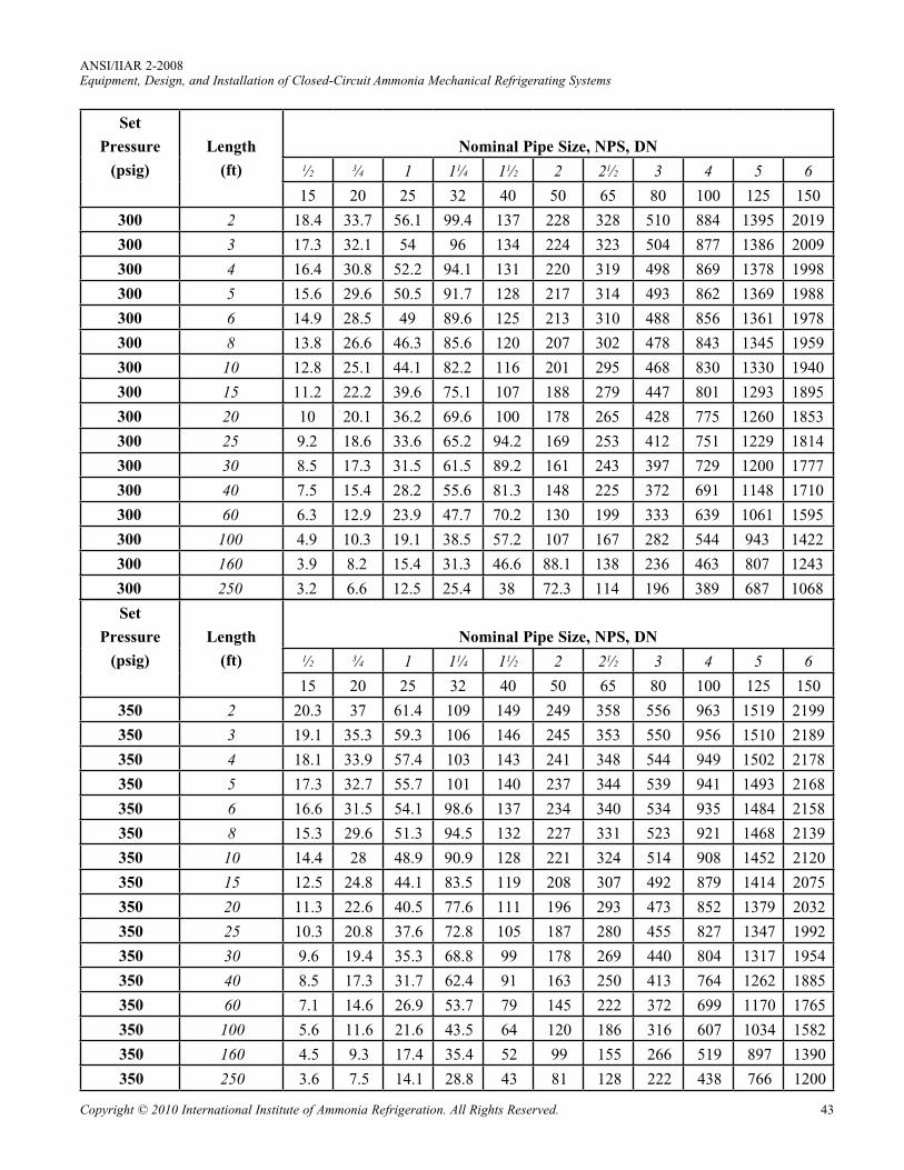
Copyright © 2010 International Institute of Ammonia Refrigeration. All Rights Reserved. 43
ANSI/IIAR 2-2008Equipment, Design, and Installation of Closed-Circuit Ammonia Mechanical Refrigerating Systems
Set
Pressure
(psig)
Length
(ft)
Nominal Pipe Size, NPS, DN1⁄2 3⁄4 1 11⁄4 11⁄2 2 21⁄2 3 4 5 6
15 20 25 32 40 50 65 80 100 125 150
300 2 18.4 33.7 56.1 99.4 137 228 328 510 884 1395 2019
300 3 17.3 32.1 54 96 134 224 323 504 877 1386 2009
300 4 16.4 30.8 52.2 94.1 131 220 319 498 869 1378 1998
300 5 15.6 29.6 50.5 91.7 128 217 314 493 862 1369 1988
300 6 14.9 28.5 49 89.6 125 213 310 488 856 1361 1978
300 8 13.8 26.6 46.3 85.6 120 207 302 478 843 1345 1959
300 10 12.8 25.1 44.1 82.2 116 201 295 468 830 1330 1940
300 15 11.2 22.2 39.6 75.1 107 188 279 447 801 1293 1895
300 20 10 20.1 36.2 69.6 100 178 265 428 775 1260 1853
300 25 9.2 18.6 33.6 65.2 94.2 169 253 412 751 1229 1814
300 30 8.5 17.3 31.5 61.5 89.2 161 243 397 729 1200 1777
300 40 7.5 15.4 28.2 55.6 81.3 148 225 372 691 1148 1710
300 60 6.3 12.9 23.9 47.7 70.2 130 199 333 639 1061 1595
300 100 4.9 10.3 19.1 38.5 57.2 107 167 282 544 943 1422
300 160 3.9 8.2 15.4 31.3 46.6 88.1 138 236 463 807 1243
300 250 3.2 6.6 12.5 25.4 38 72.3 114 196 389 687 1068
Set
Pressure
(psig)
Length
(ft)
Nominal Pipe Size, NPS, DN1⁄2 3⁄4 1 11⁄4 11⁄2 2 21⁄2 3 4 5 6
15 20 25 32 40 50 65 80 100 125 150
350 2 20.3 37 61.4 109 149 249 358 556 963 1519 2199
350 3 19.1 35.3 59.3 106 146 245 353 550 956 1510 2189
350 4 18.1 33.9 57.4 103 143 241 348 544 949 1502 2178
350 5 17.3 32.7 55.7 101 140 237 344 539 941 1493 2168
350 6 16.6 31.5 54.1 98.6 137 234 340 534 935 1484 2158
350 8 15.3 29.6 51.3 94.5 132 227 331 523 921 1468 2139
350 10 14.4 28 48.9 90.9 128 221 324 514 908 1452 2120
350 15 12.5 24.8 44.1 83.5 119 208 307 492 879 1414 2075
350 20 11.3 22.6 40.5 77.6 111 196 293 473 852 1379 2032
350 25 10.3 20.8 37.6 72.8 105 187 280 455 827 1347 1992
350 30 9.6 19.4 35.3 68.8 99 178 269 440 804 1317 1954
350 40 8.5 17.3 31.7 62.4 91 163 250 413 764 1262 1885
350 60 7.1 14.6 26.9 53.7 79 145 222 372 699 1170 1765
350 100 5.6 11.6 21.6 43.5 64 120 186 316 607 1034 1582
350 160 4.5 9.3 17.4 35.4 52 99 155 266 519 897 1390
350 250 3.6 7.5 14.1 28.8 43 81 128 222 438 766 1200

44 Copyright © 2010 International Institute of Ammonia Refrigeration. All Rights Reserved.
ANSI/IIAR 2-2008Equipment, Design, and Installation of Closed-Circuit Ammonia Mechanical Refrigerating Systems
Set
Pressure
(psig)
Length
(ft)
Nominal Pipe Size, NPS, DN1⁄2 3⁄4 1 11⁄4 11⁄2 2 21⁄2 3 4 5 6
15 20 25 32 40 50 65 80 100 125 150
400 2 22 40.2 66.6 118 162 270 387 601 1041 1642 2376
400 3 20.9 38.5 64.5 115 158 266 382 595 1034 1633 2366
400 4 19.8 37 62.5 122 155 262 378 589 1026 1625 2355
400 5 18.9 35.7 60.7 110 152 258 373 584 1019 1616 2345
400 6 18.2 34.5 59.1 107 150 254 369 578 1012 1608 2335
400 8 16.9 32.5 56.1 103 145 247 360 568 999 1591 2315
400 10 15.8 30.7 53.6 99.3 140 241 353 558 986 1575 2295
400 15 13.9 27.4 48.5 91.5 130 227 335 535 955 1537 2249
400 20 12.5 24.9 44.6 85.2 122 215 320 515 927 1502 2205
400 25 11.4 23 41.6 80.1 115 205 307 497 902 1469 2164
400 30 10.6 21.5 39 75.8 110 197 296 481 878 1438 2125
400 40 9.4 19.2 35.1 68.9 100 182 276 453 836 1382 2052
400 60 7.9 16.2 26.9 59.4 87.2 160 246 409 767 1286 1927
400 100 6.2 12.9 24 48.3 71.5 133 207 349 669 1143 1734
400 160 5 10.4 19.4 39.3 58.5 110 173 294 574 996 1529
400 250 4 8.4 15.7 32 47.9 90.9 143 246 468 854 1324

Copyright © 2010 International Institute of Ammonia Refrigeration. All Rights Reserved. 45
ANSI/IIAR 2-2008Equipment, Design, and Installation of Closed-Circuit Ammonia Mechanical Refrigerating Systems
Appendix C (Informative)
Ammonia Characteristics and Properties
(These appendices are not part of this standard. They are merely informative and do not contain requirements necessary for conformance to the standard. They have not been processed according to the ANSI requirements for a standard and may contain material that has not been subject to public review or a consensus process.)
C.1 Ammonia Characteristics
The term ammonia, as used in this standard, refers to the compound formed by combination of nitrogen and hydrogen, having the chemical formula NH
3. It is not to be confused with aqua
ammonia, which is a solution of ammonia gas in water. Whenever the term ammonia appears in this standard, it means refrigerant-grade anhydrous ammonia.
Experience has shown that ammonia is difficult to ignite and, under normal conditions, is a very stable compound. It requires temperatures of 840-930°F [450-500°C][723.2-773.2K] to cause it to dissociate slightly at atmospheric pressure. The flammable limits at atmospheric pressure are 15.5% to 27% by volume of ammonia in air. An ammonia-air mixture in an iron flask does not ignite below 1204°F [651.1°C][925.3K].
Since ammonia is self-alarming, it serves as its own warning agent so that a person is not likely to voluntarily remain in concentrations which are hazardous.
Appendix B (Normative)
Minimum Values of Design Pressure and Leak Test Pressure – NH3
Compressors LP Side
Components IncludingVessels, HeatExchangers,Evaporators,Pumps & Piping
Hot GasDefrostEvaporators& Piping
HP Side ComponentsIncluding Valves,Sensing Devices, Heat Exchangers, Condensers, Pumps & Piping
LP Side& Boosters
HP Side Water-cooledSystems
Air-cooledSystems
psig 150 300 150 250 250 300
kPa gage 1030 2070 1030 1720 1720 2070

46 Copyright © 2010 International Institute of Ammonia Refrigeration. All Rights Reserved.
ANSI/IIAR 2-2008Equipment, Design, and Installation of Closed-Circuit Ammonia Mechanical Refrigerating Systems
C.2 Physical Properties of Ammonia
English Common Metric
SI
Molecular symbol NH3
NH3
NH3
Molecular weight 17.031 lb/lb-mol
17.031 g/mol 17.031 g/mol
Boiling point at one atmosphere* -27.99°F -33.33°C 239.82K
Freezing point at one atmosphere* -107.78°F -77.66°C 195.5K
Critical temperature 269.99°F 132.22°C 405.37K
Critical pressure 1644 psig 115.6 kg/cm2
(gage)11.34 MPa
(gage)
Latent heat at -28°F (-33°C)(240.15K) and one atmosphere 588.8 Btu/lb 327.1 cal/g 1.369 MJ/kg
Relative density of vapor compared to dry air at 32°F (0°C)(273.15K) and one atmosphere
0.5967 0.5967 0.5967
Vapor density at -28°F (-33°C)(240.15K) and one atmosphere 0.05554 lb/ft3 0.8896 kg/m3 0.8896 kg/m3
Specific gravity of liquid at -28°F (-33°C)(240.15K) compared to water at 39.4°F (4.0°C) (277.1K)
0.6816 0.6816 0.6816
Liquid density at -28°F (-33°C)(240.15K) and one atmosphere*
42.55 lb/ft3 681.6 kg/m3 681.6 kg/m3
Specific volume of vapor at 32°F (0°C)(273.15K) and one atmosphere*
20.80 ft3/lb 1.299 m3/kg 1.299 m3/kg
Flammable limits by volume in air at atmospheric pressure 15.5% to 27% 15.5% to 27% 15.5% to 27%
Ignition temperature 1204°F 651.1°C 924.13K
Specific heat, gas at 59°F (15°C)(288.15K) and one atmosphere*
At constant pressure (cp )
At constant volume (cv )
0.5184 Btu/lb°F
0.3928 Btu/lb°F
0.5184 cal/g°C
0.3928 cal/g°C
2.1706 kJ/kg K
1.6444 kJ/kg K
Ratio of specific heats k(cp/c
v, also γ) at 50°F (15°C)
(288.15K) and one atmosphere*1.320 1.320 1.320
NOTE:
*One standard atmosphere = 14.696 psia [1.0333 kg/cm2 absolute][101.33 kPa absolute]

Copyright © 2010 International Institute of Ammonia Refrigeration. All Rights Reserved. 47
ANSI/IIAR 2-2008Equipment, Design, and Installation of Closed-Circuit Ammonia Mechanical Refrigerating Systems
Appendix D (Informative)
Duplicate Nameplates on Pressure Vessels
The ASME Boiler and Pressure Vessel Code [ref.4.1.1] permits duplicate (or secondary) nameplates on pressure vessels. Duplicate nameplates may be desirable in certain circumstances, especially where the original nameplate may be obscured by insulation.
Experience has shown that attempting to access the original nameplate for inspection through windows, removable insulation sections, stanchion mounting, etc. tends to compromise the integrity of the insulation system. Moisture ingress into the insulation system follows, with possible damage to the pressure vessel. The use of duplicate nameplates helps prevent vessel damage from inspection ports and other deliberate damage to insulation.
Unfortunately, using duplicate nameplates creates the possibility that the wrong (duplicate) nameplate will be applied to a vessel. The ASME Boiler and Pressure Vessel Code [ref.4.1.1] specifies that the vessel manufacturer must ensure that the duplicate nameplate is properly applied. While the easiest way to accomplish this is for the manufacturer to weld the nameplate to a support or other permanent vessel appurtenance that will not be insulated, field installation is also permitted. (Some inspection
authorities consider the insulation jacket as a permanent attachment to the vessel, and therefore the duplicate nameplate may be applied to the jacket.) The manufacturer’s procedures for ensuring a proper match of duplicate to original must be rigorously followed. It is advisable to record the location of the original nameplate should inspection be necessary.
Various inspection authorities such as State vessel inspectors may demand to inspect and/or approve the duplicate and original nameplates before insulation is applied. While many inspection bodies will accept a duplicate nameplate as evidence of ASME Boiler and Pressure Vessel Code [ref.4.1.1] compliance for an insulated vessel, authorized inspectors may always demand to inspect the original vessel, including its nameplate. In particular, when the inspector is concerned about the physical condition of the vessel or questions the provenance of the duplicate nameplate, he or she may require the entire insulation system or any part to be removed to permit inspection. Damage to the insulation system must be promptly and professionally repaired, and due allowance should be made for the shorter service life of the repaired insulation system.
Appendix E (Informative)
Method for Calculating Discharge Capacity of Positive Displacement Compressor Pressure Relief DeviceReprinted by permission of The American Society of Heating, Refrigerating and Air-conditioning Engineers.
The following calculation method provides the required discharge capacity of the compressor pressure relief device in 6.1.2.1.
Wr = Q • PL • η
v (E.1)
v
g
where
Wr = mass flow of refrigerant, lb
m/min [kg/s]
Q = swept volume flow rate of compressor, ft3/min [m3/s]
PL = fraction of compressor capacity at minimum regulated flow

48 Copyright © 2010 International Institute of Ammonia Refrigeration. All Rights Reserved.
ANSI/IIAR 2-2008Equipment, Design, and Installation of Closed-Circuit Ammonia Mechanical Refrigerating Systems
EXAMPLE: Determine the flow capacity of a relief device for an ammonia (R-717) screw compressor with a swept volume, Q, of 1665 ft3/min (0.7858 m3/s). The compressor is equipped with capacity control that is actuated at 90% of the pressure relief device set pressure to its minimum regulated flow of 10%.
Q = 1665 ft3/min (0.7858 m3/s)
ηv = 0.90 (assumed)
PL = 0.1
vg = 3.2997 ft3/lb
m (0.206 m3/kg)
1665
ft3 • 0.1 • 0.9
W
r =
min = 45.4
lbm
3.2997
ft3 min lb
m
0.7858
m3 • 0.1 • 0.9
W
r =
s = 0.343
kg
0.206
m3 s kg
Wa = W
r • r
w = 45.4 • 1.28 = 58.1
lbm of air
min
Wa = W
r • r
w = 0.343 • 1.28 = 0.439
kg air
s
Converting to standard cubic feet/minute (SCFM), where V
a= specific volume of air = 13.1 ft3/lb
m
(0.818 m3/kg) for dry air at 60°F (15.6°C),
SCFM = 13.1(58.1) = 761 ft3/min
[SCFM = 0.818(0.439) = 0.359 m3/s].
ηv = volumetric efficiency (assume 0.9 unless
actual volumetric efficiency at relieving pressure is known)
vg = specific volume of refrigerant vapor (rated at
50°F [10°C] saturated suction temperature), ft3/lb
m [m3/kg]
Next, find the relieving capacity in mass flow of air, W
a, for an ASME-rated [ref.4.1.1] pressure relief
device: W
a = W
r r
w (E.2)
rw = c
a T
r M
a (E.3)
cr T
a M
r
where
rw = refrigerant-to-standard-air-mass-flow
conversion factor
Mr = molar mass of refrigerant (17.0 for ammonia)
Ma = molar mass of air = 28.97
Ta = absolute temperature of the air = 520 R (289 K)
ca = constant for air = 356
cr = constant for refrigerant (as determined from
Equation E.4)
Tr = absolute temperature of refrigerant = 510 R
(283 K)
k+1
2 k-1
cr = 520 k
(E.4)
k + 1
where
k = ratio of specific heats cp/c
v
cp = constant-pressure specific heat of refrigerant at
a refrigerant quality of 1 at 50°F (10°C).
cv = constant-volume specific heat of refrigerant at
a refrigerant quality of 1 at 50°F (10°C).
Constants for ammonia are listed below:
k = 1.422
Mr = 17.0
cr = 358.0
rw = 1.28

Copyright © 2010 International Institute of Ammonia Refrigeration. All Rights Reserved. 49
ANSI/IIAR 2-2008Equipment, Design, and Installation of Closed-Circuit Ammonia Mechanical Refrigerating Systems
Appendix F (Informative)
Pipe Hanger Spacing, Hanger Rod Sizing, and Loading
F.1 Recommended maximum spacing of hangers and minimum hanger rod size for steel pipe, adapted from MSS SP-69 [ref.4.2.5] is shown below. Spacing does not apply where span calculations are made or where concentrated loads such as flanges, valves, specialties, etc. are placed between supports.
Table F.1
Nominal Pipe Size
(in)
Maximum Span (ft)
Minimum Rod Diameter (in)
Up to 1 7 3⁄8
11⁄4 –11⁄2 9 3⁄8
2 10 3⁄8
21⁄2 10 1⁄2
3 12 1⁄2
4 14 5⁄8
5 16 5⁄8
6 17 3⁄4
8 19 7⁄8
10 22 7⁄8
12 23 7⁄8
14 25 1
16 27 1
18 28 11⁄4
20 30 11⁄4
F.2 The maximum recommended hanger rod loading based on threaded hot rolled steel conforming to ASTM A 575-96 [ref.4.1.3.14] is shown.
Table F.2
Rod Diameter
(in)
Maximum Load(lb)
Rod Diameter
(in)
Maximum Load(lb)
3⁄8 610 11⁄2 11 6301⁄2 1 130 13⁄4 15 7005⁄8 1 810 2 20 7003⁄4 2 710 21⁄4 27 2007⁄8 3 770 21⁄2 33 500
1 4 960 23⁄4 41 600
11⁄8 6 230 3 50 600
11⁄4 8 000 31⁄4 60 500
Adapted from MSS SP-69 [ref.4.2.5].
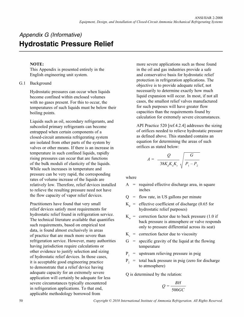
50 Copyright © 2010 International Institute of Ammonia Refrigeration. All Rights Reserved.
ANSI/IIAR 2-2008Equipment, Design, and Installation of Closed-Circuit Ammonia Mechanical Refrigerating Systems
Appendix G (Informative)
Hydrostatic Pressure Relief
NOTE: This Appendix is presented entirely in the English engineering unit system.
G.1 Background
Hydrostatic pressures can occur when liquids become confined within enclosed volumes with no gases present. For this to occur, the temperatures of such liquids must be below their boiling points.
Liquids such as oil, secondary refrigerants, and subcooled primary refrigerants can become entrapped when certain components of a closed-circuit ammonia refrigerating system are isolated from other parts of the system by valves or other means. If there is an increase in temperature in such confined liquids, rapidly rising pressures can occur that are functions of the bulk moduli of elasticity of the liquids. While such increases in temperature and pressure can be very rapid, the corresponding rates of volume increase of the liquids are relatively low. Therefore, relief devices installed to relieve the resulting pressure need not have the flow capacity of vapor relief devices.
Practitioners have found that very small relief devices satisfy most requirements for hydrostatic relief found in refrigeration service. The technical literature available that quantifies such requirements, based on empirical test data, is found almost exclusively in areas of practice that are much more severe than refrigeration service. However, many authorities having jurisdiction require calculations or other evidence to justify selection and sizing of hydrostatic relief devices. In those cases, it is acceptable good engineering practice to demonstrate that a relief device having adequate capacity for an extremely severe application will certainly be adequate for less severe circumstances typically encountered in refrigeration applications. To that end, applicable methodology borrowed from
more severe applications such as those found in the oil and gas industries provide a safe and conservative basis for hydrostatic relief protection in refrigeration applications. The objective is to provide adequate relief, not necessarily to determine exactly how much liquid expansion will occur. In most, if not all cases, the smallest relief valves manufactured for such purposes will have greater flow capacities than the requirements found by calculation for extremely severe circumstances.
API Practice 520 [ref.4.2.4] addresses the sizing of orifices needed to relieve hydrostatic pressure as defined above. This standard contains an equation for determining the areas of such orifices as stated below:
A =
Q G
38Kd K
wK
v P
1 – P
2
where
A = required effective discharge area, in square inches
Q = flow rate, in US gallons per minute
Kd = effective coefficient of discharge (0.65 for
hydrostatic relief purposes)
Kw = correction factor due to back pressure (1.0 if
back pressure is atmosphere or valve responds only to pressure differential across its seat)
Kv = correction factor due to viscosity
G = specific gravity of the liquid at the flowing temperature
P1 = upstream relieving pressure in psig
P2 = total back pressure in psig (zero for discharge
to atmosphere)
Q is determined by the relation:
Q =
BH
500GC

Copyright © 2010 International Institute of Ammonia Refrigeration. All Rights Reserved. 51
ANSI/IIAR 2-2008Equipment, Design, and Installation of Closed-Circuit Ammonia Mechanical Refrigerating Systems
Figure G1: Capacity Correction Factor K Due to Viscosity
Figure G1 was reprinted by permission from Oil and Gas Journal, November 20, 1978 edition. Copyright 1978, Oil and Gas Journal. http://ogj.pennnet.com/home.cfm.
where
B = cubical expansion coefficient per degree Fahrenheit for the liquid at the expected temperature
H = total heat of absorption to the wetted bare surface of a vessel, pipe or container in BTU per hour
(H = 21,000 A0.82, where A = total wetted surface in square feet)
G = specific gravity of the liquid at the flowing temperature
C = specific heat of the trapped fluid in BTU per lb-°F
Kv is determined as follows:
Refer to Figure G1 below to find Kv as a function of
the Reynolds number (R), which is defined by the following equation:
R =
12,700Q
U A
where
Q = flow rate at the flowing temperature in US GPM
U = viscosity at the flowing temperature in Saybolt Universal Seconds
A = effective discharge area, in square inches (from manufacturers’ standard orifice areas)

52 Copyright © 2010 International Institute of Ammonia Refrigeration. All Rights Reserved.
ANSI/IIAR 2-2008Equipment, Design, and Installation of Closed-Circuit Ammonia Mechanical Refrigerating Systems
G.2 Hydrostatic Pressure Relief of ASME Pressure Vessels
This section pertains to vessels covered by Section VIII, Division 1, of the ASME Boiler and Pressure Vessel Code [ref.4.1.1], herein referred to as ASME pressure vessels.
When ASME pressure vessels contain liquid refrigerant and can be isolated from the other parts of a closed-circuit ammonia refrigerating system, the rules of Section 11 apply. However, when ASME pressure vessels contain a non-boiling liquid (i.e., a liquid whose vapor pressure at maximum normal operational, maintenance or standby conditions is less than the relief valve setting), specific requirements of the ASME Boiler and Pressure Vessel Code [ref.4.1.1] for hydrostatic relief valves apply: a. Hydrostatic relief valves protecting ASME pressure vessels must bear an ASME UV Code Symbol Stamp. (Code Case BC94-620) b. Hydrostatic relief valves protecting ASME pressure vessels must be certified and rated for liquid flow. (Code Case BC94-620)c. Any liquid pressure relief valve used shall be at least NPS 1/2. (UG-128)d. The opening through all pipe, fittings, and nonreclosing pressure relief devices (if installed) between a pressure vessel and its pressure relief valve shall have at least the area of the pressure relief valve inlet. In this upstream system, the pressure drop shall not reduce the relieving capacity below that required or adversely affect the proper operation of the pressure relief valve. (UG-135 (b) (1))e. The size of the discharge lines leaving a hydrostatic relief valve shall be such that any pressure that may exist or develop will not reduce the relieving capacity of the pressure relief valve below that required to properly protect the vessel. (UG-135 (f))f. The hydrostatic relief valve shall be capable of preventing the pressure from rising more than 10% above the maximum allowable working pressure during normal service or standby conditions.
G.3 Sample calculations
To illustrate how to apply these concepts and requirements, two examples of sizing hydrostatic relief valves for pressure-containing components are provided below.
NOTE: These examples are for oil in the oilside of oil coolers rather than ammonia on the refrigerant side.
EXAMPLE 1: Sizing a Hydrostatic Relief Valve for an ASME Pressure Vessel
Determine the hydrostatic relief valve required to protect an oil cooler of diameter 10" and length 12 ft with MAWP 400 psig.
Assume that the oil temperature is 100°F and that the oil viscosity (U) is 300 Saybolt Universal Seconds at 100°F. From the oil manufacturer’s data, the cubical expansion coefficient (B) is 0.00043/°F, specific gravity (G) is 0.87 and specific heat (C) is 0.5.
First, determine the bare wetted external area (A) of the oil cooler, in square feet:
A = πdl = π 10.75
× 12 = 33.8 ft2
12
Next, determine total heat absorption (H) of the wetted bare surface of the oil cooler when exposed to maximum normal conditions:
H = 21,000 A0.82
H = 21,000 × (33.8)0.82 = 376,644 Btu/Hr.
Next, determine rate of increase of the oil volume from the relation below:
Q =
BH
500GC
Q =
0.00043 × 376,644 = 0.74 gpm
500 × 0.87 × 0.5
Assume the relief valve will discharge into

Copyright © 2010 International Institute of Ammonia Refrigeration. All Rights Reserved. 53
ANSI/IIAR 2-2008Equipment, Design, and Installation of Closed-Circuit Ammonia Mechanical Refrigerating Systems
another part of the system having relief protection set at 300 psig. To prevent the pressure in the oil cooler from exceeding 400 psig under all conditions, the hydrostatic relief valve must be selected for 100 psi differential.
A liquid-rated ASME certified relief valve is commercially available with 1/2" NPT inlet and 3/4" NPT outlet. The valve’s capacity at 100 psi pressure differential is 25.9 gal per min, 35 times the oil volume rate of increase. The valve therefore meets all ASME requirements. Per the ASME code, total inlet and outlet pressure losses may total 40 psi and still meet code requirements.
EXAMPLE 2: Sizing a Hydrostatic Relief Valve for a non-ASME component
Determine the orifice area required to protect an oil cooler with diameter 5" and length 12 feet with MAWP 400 psig.
Assume that the oil temperature is 100°F and oil viscosity (U) is 300 Saybolt Universal Seconds at 100°F. From the oil manufacturer’s data, the cubical expansion coefficient (B) is 0.00043/°F, specific gravity (G) is 0.87 and specific heat (C) is 0.5.
First, determine the bare wetted external area of the oil cooler, in square feet:
A = πdl = π 5.563
× 12 = 17.48 ft2
12
Next, determine total heat absorption of the wetted bare surface of the oil cooler when exposed to maximum normal conditions from the relation:
H = 21,000 A0.82, outlined above.
H = 21,000 × (17.48)0.82 = 219,298 Btu/hr.
Next, determine rate of increase of the oil volume from the relation:
Q =
BH
500GC
Q =
0.00043 × 219,298 = 0.433 gpm
500 × 0.87 × 0.5
Next, determine the viscosity correction factor (K
v) from Figure G1 and the Reynolds number
(R) from the formula below:
R =
12,700Q
U A
To calculate R in this equation requires a value for A, which represents the orifice area. Interestingly, to calculate A using the primary equation requires a value for R. To solve this problem, an iterative method (trial and error) must be used. First, an approximate starting value of A must be estimated to obtain an initial estimate of R, which can then be used in the primary equation to calculate a new value for A. Comparing this calculated value of A to the initial approximation for A will enable a even better approximation for A for the next iteration. This iterative process will converge on a calculated value for A that is reasonably close to the final approximation for A. If it does not, more sophisticated mathematical methods are required to solve the equations.
Try a 1/16" orifice having an area of 0.003068 in2.
R = 12,700 × 0.433
= 331
300 0.003068
From Figure G1, Kv = 0.825
A =
Q G
38Kd K
wK
v P
1 – P
2
Assume the pressure differential to another part of the system (P
1-P
2) is 100 psi.
A =
0.433 0.87 = 0.00198 in2
38×0.65×1×0.825 100
The required flow area is much smaller (0.00198 in2) than the area assumed in estimating the Reynolds number (0.003068 in2). Therefore, a relief valve having a 1/16" diameter orifice is more than adequate.
For a second iteration, assume a 3/64" orifice with 0.0017 in2 cross-sectional area. R would then become

54 Copyright © 2010 International Institute of Ammonia Refrigeration. All Rights Reserved.
ANSI/IIAR 2-2008Equipment, Design, and Installation of Closed-Circuit Ammonia Mechanical Refrigerating Systems
R = 12,700 × 0.433
= 445
300 0.0017
Kv = 0.85
A = 0.433 0.87
= 0.00192 in2
38×0.65×1×0.85 100
This area requirement is approximately 13% greater than that of the 3/64" orifice. Therefore, we can conclude that an orifice between a diameter of 1/16" and 3/64" would be ideal. A 1/16" orifice will be more than adequate.
G.4 Inlet and Outlet Piping
The ASME Boiler and Pressure Vessel (B & PV) Code [ref.4.1.1] requires that hydrostatic relief valve inlet piping for ASME pressure vessels must have at least the area of the pressure relief valve inlet. Since the same code requires a minimum NPS 1/2" valve, the minimum inlet piping is established. Inlet piping requirements on larger hydrostatic relief valves would follow suit.
On outlet piping, the B & PV Code simply requires that the relief valve discharge lines are large enough to avoid reducing the relieving capacity of the pressure relief device below that required to properly protect the vessel. For normal over-pressure protection, ASME permits overpressurization of a vessel to 10% above its MAWP.
In the previous examples, the flows of liquid created by thermal expansion were very low. Consequently, outlet piping from commercially available certified ASME liquid relief valves could usually be much smaller than the nominal outlets of the valves themselves. For instance, consider the ASME vessel example with a 0.74 gpm relief requirement. The relief valve suggested for this application has a 3/4" NPT
connection on the outlet. If, for example, the discharge piping is reduced to 1/2” in stainless steel tubing, the Reynolds number for oil having a nominal viscosity of 68 centistokes at 100° F is less than 60 (57.9). In laminar flow, which by definition is flow at or below Reynolds numbers of 2000, pressure loss to friction in psi per 100 ft of smooth pipe is given as:
h
f =
43.3V2 G
RD
where
V = fluid velocity in ft/sec
G = specific gravity of fluid
R = Reynolds Number of fluid
D = I.D. of pipe in ft
From the previous example, oil flow due to thermal expansion is 0.74 gpm or 0.1 cfm. The 1/2" stainless steel tubing has a cross-sectional flow area of 1.0085 x 10⁻³ ft2. Fluid velocity is therefore:
V = cfm
ft/sec = 0.1
= 1.65 ft/sec 60A 60×1.0085×10-3
Discharge piping pressure drop through the 1/2" stainless tubing would therefore be:
hf =
43.3V2G =
43.3×1.652×0.867 = 49.3 psi/100 ft
RD 57.9×0.0358
For a typical relief valve discharge pipe run of 6 ft, pressure drop due to friction would be less than 3 psi. Because ASME permits overpressurization of 10% above the MAWP of a pressure vessel, inlet and outlet losses could total 40 psi and meet ASME requirements. Therefore, hydrostatic relief valve outlet piping can be greatly reduced below the nominal outlet size of the relief valve selected in many cases.

Copyright © 2010 International Institute of Ammonia Refrigeration. All Rights Reserved. 55
ANSI/IIAR 2-2008Equipment, Design, and Installation of Closed-Circuit Ammonia Mechanical Refrigerating Systems
Inlet and outlet piping for hydrostatic relief valves protecting non-ASME components containing incompressible non-refrigerants can be sized using identical techniques. In providing hydrostatic protection against ambient warming, 10% overpressurization above MAWP is permitted, providing the relief valve is selected at MAWP.
Hydrostatic relief devices may be located anywhere on the protected component. When used to protect an ASME vessel, they must bear a UV Code Symbol. When used to protect a non-ASME component, they must be listed by an approved nationally recognized testing laboratory or bear a UV Code Symbol.

56 Copyright © 2010 International Institute of Ammonia Refrigeration. All Rights Reserved.
ANSI/IIAR 2-2008Equipment, Design, and Installation of Closed-Circuit Ammonia Mechanical Refrigerating Systems
Appendix H (Informative)
Insulation for Refrigeration Systems
Chapter 7 of the IIAR Piping Handbook [ref.4.2.2.3] covers insulation systems operating on below-ambient temperature piping systems ranging from +50°F to –100°F for piping, fittings, valves, vessels, equipment and heat exchangers typically used in industrial refrigeration systems.
H.1 Purpose
The purpose of the insulation system is to conserve energy by preventing heat infiltration, preventing condensation or ice formation, and minimizing corrosion.
The success of an insulation system for cold piping depends upon four factors: proper pipe preparation, correct refrigeration and insulation system design, adequate insulation thickness, and proper installation of the insulation and related materials such as vapor retarders, sealants, and protective jacketing. It is critical to maintain the integrity of the vapor retarder system. The insulating system must be regularly maintained and inspected after installation.
H.2 Fundamentals of Insulation
Heat is a form of energy, always moving from a higher to a lower temperature.
There are three types of heat transfer: conduction, through direct thermal contact between a hotter and a colder material, convection, through natural or forced circulation of a fluid, and radiation, through exchange of the infrared energy naturally given off by every object. Poor heat conductors are good insulation products. Water is a good conductor of heat. Water and water vapor are the prime enemy of an insulation system.
H.3 Design Considerations
When designing thermal insulation for a refrigeration system, consider thermal and mechanical factors, as well as process control issues.
In general, provide sufficient insulation to maintain an 8–10 BTU/hr heat gain per square foot of pipe surface. Recommended thickness tables can be found in Chapter 7 of the IIAR Piping Handbook [ref.4.2.2.3].
H.4 Effect of Water/Ice/Moisture on Insulation Value
Refrigerant systems are insulated to conserve energy and prevent surface condensation or “sweating.”
When high absorption/permeability materials are used on these systems and the vapor retarder system fails, water vapor will move into the insulation condensing and eventually saturating the insulation material. This problem is more severe at lower system temperatures and when the system operates continuously in the cold mode. As more water vapor is absorbed, the thermal conductivity of the insulation material increases, lowering the surface temperature of the pipe.
Lower surface temperatures lead to more condensation which may eventually lead to insulation system freeze-up, frost-ups and total failure of the insulation material due to ice formation and water expansion, as well as corrosion of metal components.
H.5 Insulation Material Selection
Choose insulation material for suitability at both minimum and maximum system operating temperatures.

Copyright © 2010 International Institute of Ammonia Refrigeration. All Rights Reserved. 57
ANSI/IIAR 2-2008Equipment, Design, and Installation of Closed-Circuit Ammonia Mechanical Refrigerating Systems
The manufacturer generally specifies the intended operating temperature ranges for an insulation material, based on thermal properties in that temperature range.
H.6 Corrosion Concerns
Piping systems corrode not because they are insulated, but because they are in contact with aerated water and/or a water-borne corrosive chemical.
Corrosion can occur under all types of insulation. Corrosion is caused by moisture ingress as a result of improper vapor retarder selection, installation, or maintenance, or mechanical abuse, or of voids in the insulation system that retain water.
Equipment or piping operating either steadily or cyclically at or above freezing (such as hot gas defrost systems) may experience significant corrosion problems. Pipe legs or instruments protruding into ambient-temperature areas may corrode faster than cold, insulated pipe mains.
Some areas of a piping system are more susceptible to corrosion than others. Where the risk of corrosion is elevated, apply a primer-paint coating system. The higher-risk areas include (but are not limited to) all pipe welds, control valve groups, areas around pump bases or control columns, evaporator coil headers, oil pots, valves, unions and flanges or any termination of insulation.
H.7 Insulation System Components
Many low temperature insulation products may perform reliably with proper installation and application of accessory materials.
The insulation itself should be a low thermal conductivity material with low water vapor permeability and it should provide moisture resistance. The types of insulation commonly used in industrial refrigeration
are: extruded polystyrene insulation, cellular glass, polyisocyanurate insulation (The terms polyisocyanurate (PIR) and polyurethane (PU) are frequently used interchangeably. The two products use the same raw materials, in different ratios) and closed-cell phenolic.
Use a joint sealant on all insulations operating at below-ambient conditions. The sealant should be resistant to liquid water and to water vapor and be able to bond to the specific insulation surface. Use low-permeance insulation materials and a continuous, effective vapor retarder system.
Jacketing on insulated refrigeration piping protects the insulation and vapor retarder from damage.
Use protective jacketing. Seal all lap joints with appropriate weather barrier sealant.
H.8 Recommended Practices for Insulation Applications
Chapter 7 of the IIAR Piping Handbook [ref.4.2.2.3] covers recommended specifications and design features for typical refrigeration insulation applications. Also check State and local building codes for requirements.
Store insulation in a cool, dry location and protect it from the weather before and during application. Install vapor retarders and weather barriers over dry insulation.
Finish all welding and other hot work, as well as all pressure testing, before installing pipe insulation. The surfaces to be insulated should be free from all oil, grease, loose scale, rust and foreign matter and must be dry and free from frost. Complete site touch-up of shop coating (including preparation and painting at field welds) before insulating. For insulation and insulation accessories, use specific manufacturer instructions.

58 Copyright © 2010 International Institute of Ammonia Refrigeration. All Rights Reserved.
ANSI/IIAR 2-2008Equipment, Design, and Installation of Closed-Circuit Ammonia Mechanical Refrigerating Systems
Appendix I (Informative)
Purging
A noncondensible gas separator (purger) separates, collects, and removes air and other gases from the closed-circuit ammonia refrigerating system. It is useful in most refrigeration plants.
Noncondensibles occur in systems from many causes. In systems operating below atmospheric pressure, air may be drawn through leaking packing, gaskets, rotary seals, or piping. Air can be introduced by improper charging or draining of ammonia or oil. In all systems, noncondensibles may remain after an inadequate evacuation of pressure test gas. Air may be introduced when the system has been opened for service or repair. Also, noncondensibles can occur from the breakdown of ammonia into nitrogen and hydrogen or water, or through the breakdown of oil into hydrocarbon gases and other salts, acids and sludge.
The result of noncondensible gases in the system is an increase in discharge pressure
above normal. Higher discharge pressures cause a loss of system capacity concurrent with an increase in operating energy costs.
In the absence of automatic purgers, manual purging can be done by opening purge valves on tops of receivers or condensers unless prohibited by governing regulations. Purging can be accomplished during operation, but is likely to be more effective when the system is shut down. Since noncondensibles diffuse homogeneously with ammonia vapor, manual purging must be repeated several times to be effective. A more effective purging method is to nearly fill the component being purged with liquid ammonia, thus delivering the mixture of noncondensibles and ammonia vapor to the vicinity of the purge connection.
See the ASHRAE Refrigeration Handbook [ref.4.2.6] for additional information.
Appendix J (Informative)
Stress Corrosion Cracking
J.1 Background
Stress corrosion cracking (SCC) is a generic term describing the initiation and propagation of cracks that can occur in metals when subjected to stress in the presence of an enabling chemical environment. The stress can originate from an externally applied force, thermal stress, or residual stress from welding or forming.
J.2 Carbon steel is susceptible to SCC when stressed in the presence of ammonia and oxygen. Ammonia SCC has been recognized as a problem in the agricultural, chemical, and transport industries for many years. Studies have shown that the following factors contribute to the likelihood of SCC:
• Material yield strength greater than 50 ksi • Oxygen contamination • Residual or applied stress• Water content less than 0.2%

Copyright © 2010 International Institute of Ammonia Refrigeration. All Rights Reserved. 59
ANSI/IIAR 2-2008Equipment, Design, and Installation of Closed-Circuit Ammonia Mechanical Refrigerating Systems
J.3 SCC in Ammonia Refrigeration Systems
SCC in ammonia refrigeration systems is less common, but there have been reports of SCC in vessels and piping. Vessels seem to be more susceptible to SCC because of their higher material yield strengths and residual fabrication stresses. High pressure receivers are particularly vulnerable due to their potential for higher oxygen content (noncondensibles) and lower water content but SCC has also been found in low pressure vessels and piping.
Propagation of cracks via SCC is usually a gradual process. In ammonia refrigeration applications using carbon steel materials, stress corrosion cracks typically propagate from surface or subsurface discontinuities at the interior wall of a susceptible vessel or pipe. Sufficiently high stresses can propagate crack(s) through the material to emerge as a “pinhole leak” on the external surface. Discovery of a “pinhole leak” on a vessel is indicative of SCC and it is likely that additional cracks will be present in the same vessel. Repair of stress corrosion cracks is difficult and often not cost-effective.
J.4 Recommendations to Inhibit SCC in Ammonia Refrigeration Systems
The following recommendations are intended to minimize the likelihood of SCC for vessels constructed from carbon steel for use in ammonia refrigeration systems.• The presence of noncondensible gases (specifically, oxygen) increases the probability
of SCC. As such, purging of air from the system during both initial start-up and during operation and maintenance is important. At initial start-up and during commissioning, refer to evacuation recommendations in Section 5.5 of IIAR Bulletin 110. During refrigeration system operation, refer to air purging recommendations in Appendix I.• Post-weld heat treat (PWHT) all high temperature vessels, especially vessels such as receivers, water chillers, intercoolers and economizers, to relieve the residual stress of welding and forming. Where low temperature vessels are critical to the process, or may be held at temperatures above 23°F (-5°C) for long periods of time, consideration should be given to PWHT.
EXCEPTIONS: a. compressor oil separatorsb. specialized vessels, such as plate heat exchangers, containing internal components that could be damaged, e.g. internal bushings, gaskets.
NOTE: PWHT may produce significant scale, which could cause operating problems in the system.
J.5 Refrigerant-grade anhydrous ammonia should meet or exceed the requirements of Federal Specification 0-A-445C, Ammonia, Technical [ref. 4.2.1].

60 Copyright © 2010 International Institute of Ammonia Refrigeration. All Rights Reserved.
ANSI/IIAR 2-2008Equipment, Design, and Installation of Closed-Circuit Ammonia Mechanical Refrigerating Systems
Emergency Pressure Control System Design and Installation Guidelines
K.1 General
K.1.1 Purpose. This technical guideline describes requirements for Emergency Pressure Control Systems (EPCS), which provide a means of internally mitigating an overpressure event in a refrigeration system that is independent of other required safety features and functions prior to operation of a pressure relief device.
K.1.2 Scope. Emergency Pressure Control Systems used as a means to mitigate an overpressure event involving an ammonia refrigeration system should comply with this technical guideline.
K.1.3 Limitations. An EPCS does not reduce or eliminate requirements for pressure relief devices set forth in other codes and standards.
K.2 Definitions
crossover valve is a valve that allows interconnection of two different portions of a refrigeration system that normally operate at different pressures.
emergency pressure control system (EPCS) is a system consisting of pressure sensors, independent compressor cut-off controls and automatically controlled crossover valves that will permit a high-pressure portion of a system to connect to a lower pressure portion of a system when opened.
header is a pipe to which other pipes or tubes are connected.
high side consists of those parts of a mechanical refrigerating system that are subjected to approximate condenser pressure.
low side consists of those parts of a mechanical refrigerating system that are subjected to approximate evaporator pressure.
pressure sensor is a mechanical or electronic device that measures ammonia pressure.
seep is a nuisance loss of refrigerant from a relief valve that can occur when the vessel pressure approaches the relief pressure setting, or a nuisance loss of refrigerant from a relief valve that can occur after the valve discharges if the valve does not fully re-seat.
zone is a general term used to identify a pressure level or temperature level of a refrigeration system. A zone will be associated with a compressor or group of compressors and the associated vessels serving a common pressure level. The term does not pertain to individual temperature controlled areas or rooms served by one or more compressor.
K.3 Referenced Standards
K.3.1 ANSI/ASHRAE Standard 15-2007
K.4 EPCS Recommended. Each zone should be provided with an EPCS. Each EPCS, other than the lowest pressure zone, should include a crossover valve to allow an abnormally high pressure to be discharged to a lower pressure zone.
K.4.1 Design and Installation Recommendations
K.4.2 Crossover Valve Connections.
K.4.2.1 Crossover valves should be connected to locations that will allow pressure in each high pressure zone to discharge to a lower pressure zone. Connections between pressure zones should continue in the above-described manner until all major pressure zones in a system are connected with the EPCS, always with
Appendix K (Informative)
Emergency Pressure Control Systems

Copyright © 2010 International Institute of Ammonia Refrigeration. All Rights Reserved. 61
ANSI/IIAR 2-2008Equipment, Design, and Installation of Closed-Circuit Ammonia Mechanical Refrigerating Systems
the intended flow traveling from a high pressure to a lower pressure.
K.4.2.2 Where multiple low-pressure zones are present, low-pressure zones with the highest pressure should be connected to the next lowest pressure zone.
K.4.2.3 Crossover valve connections should not be to pipes or tubes conveying liquid refrigerant.
K.4.2.4 High pressure crossover valve connections should come from the top of a dry suction header, compressor discharge header or other main gas header.
K.4.2.5 Low pressure crossover valve connections should discharge to the vapor space in a receiving vessel or to a common vapor header serving multiple receiving vessels.
K.4.2.6 The designer of a refrigeration system should consider the ability of the low pressure portion of the system to receive the high pressure discharge from the EPCS crossover valve. Operation of the crossover valve should not cause a release of refrigerant from pressure relief devices on the low pressure portion of the system.
K.4.2.7 Crossover valves and connecting piping and valves should have an internal diameter of not less than 1-inch.
K.4.2.8 Piping and tubing associated with a crossover valve should be independent of any other connections. The connection should not be in the same pipe or tube where a pressure relief device is connected.
K.4.3 Crossover Valve Type. The crossover valve should be of a type that fully opens when activated.
K.4.4 Isolation Valves
K.4.4.1 Each crossover valve should be provided with a stop valve on either side to allow isolation of the crossover valve for maintenance.
K.4.4.2 Isolation valves should be locked in the open position during normal operations.
K.4.5 System Operation
K.4.5.1 The EPCS should be arranged for automatic operation.
K.4.5.2 Where required by the fire department, the EPCS should be provided with a remote switch for manual activation.
K.4.5.3 An EPCS should be arranged to activate at a pressure not greater than 90 percent of the pressure relief device setting.
K.4.5.4 A dedicated, independent mechanical pressure switch or a combination of a mechanical and electronic pressure-sensing device dedicated to the EPCS should be provided to activate each EPCS.
K.4.5.5 Pressure sensing equipment should continuously monitor pressure in the refrigeration system adjacent to each crossover valve.
K.4.5.6 When a pressure sensor reaches the EPCS activation pressure, all of the following should occur:
1) All compressors supplying the pressure zone that is in an over-pressure condition should be stopped by a means that is independent of all other safety controls,
2) Associated crossover valves should open, and
3) Condenser fans and pumps should be stopped if the system pressure falls below 90 psig.
K.4.5.7 A means should be provided to signal personnel responsible for refrigeration system maintenance that an EPCS has been activated.
K.4.5.8 Once an EPCS has been activated, it should remain active until manually reset.

62 Copyright © 2010 International Institute of Ammonia Refrigeration. All Rights Reserved.
ANSI/IIAR 2-2008Equipment, Design, and Installation of Closed-Circuit Ammonia Mechanical Refrigerating Systems
K.4.6 Inspection and Maintenance
K.4.6.1 General. EPCS crossover valves and isolation valves should be inspected and tested on an annual basis to verify proper operation.
K.4.7 Written Procedures
K.4.7.1 General. Written procedures should be in place to describe the operation of the EPCS. Procedures should address the importance of maintaining isolation valves in the full open position unless maintenance is being performed on the crossover valve.
Considerations for Pressure Set Points
Seep through a relief valve is nuisance refrigerant loss due to pressure differential conditions across the valve or dirt and debris located at the seat. Seep is measured in bubbles per minute and can vary from manufacturer, design, type of seat material, pressure differential across relief, amount of dirt that is trapped after a relief discharges, and age of the relief valve. Relief valves are set with a tolerance of +/- 3%, but when these reliefs are stored or left in operation for a long period of time, the reliefs can begin to seep at larger tolerances. In some cases, seep has occurred when pressure increases to within 10% of relief set pressure.
One method to prevent seep, is to maintain a pressure on the relief valve of 90% or less of the rated relief valve pressure setting. When pressures higher than 90% of rated relief valve pressure setting are anticipated, it is possible to select soft seats that are bubble tight at higher pressures. Rupture disks in combination with a relief valve will result in tighter tolerances.
The following tables show examples of typical tolerances and pressures associated with relief valves and the EPCS.
TABLE K-1
Typical Set Point Values and Tolerances for a 300 psig System
Relief Full Open (+10%) 330 psig
+3% tolerance 309 psig
Relief Valve Set Point 300 psig
-3% tolerance 291 psig
Potential seep point (-10%) 270 psig
EPCS set point 250 psig to 270 psig (EPCS set point is equal or below the seep point)
Design System Operating Pressure (-25%) 225 psig
(system operating pressure should be 25% lower than the relief valve setting when selecting relief valves)
Compressor off set point 225 psig
TABLE K-2
Typical Set Point Values and Tolerances for a 250 psig System
Relief Full Open (+10%) 275 psig
+3% tolerance 257.5 psig
Relief Valve Set Point 250 psig
-3% tolerance 242.5 psig
Potential seep point (-10%) 225 psig (EPCS set point is equal or below the seep point)
EPCS set point 210 psig to 225 psig
Design System Operating Pressure (-25%) 200 psig
(system operating pressure should be 25% lower than the relief valve setting when selecting relief valves)
Compressor off set point 200 psig

Copyright © 2010 International Institute of Ammonia Refrigeration. All Rights Reserved. 63
ANSI/IIAR 2-2008Equipment, Design, and Installation of Closed-Circuit Ammonia Mechanical Refrigerating Systems
The following example of the Principle and Auxiliary Machinery Room doors are provided for reference only.
Key to door signage:
1. Refrigeration Machinery Room – Authorized Personnel Only
Color: Black Text, Yellow Background
Location: All entrances to Machinery Room
2. Caution – Ammonia R-717
Color: Black Text, Yellow Background
Location: All entrances to Machinery Room
3. Caution – Eye and Ear protection must be worn in this area
Color: Black Text, Yellow Background
Location: All entrances to Machinery Room
4. Warning – When alarms are activated ammonia has been detected
1. Leave room immediately when alarms are activated
2. Do not enter except by emergency trained personnel only
3. Do not enter without personal protective equipment
Location: All entrances to Machinery Room
5. Refrigeration Machinery Shutdown, Emergency use only
Color: Black Text, Orange Background
Location: Designated principal exterior machinery room door.
6. Refrigeration Machinery Room: Refrigeration Ventilation, Emergency use only
Color: Black Text, Orange Background
Location: Designated Principal Exterior Machinery Room Door, also can be used for remote On / OFF / AUTO ventilation switch.
7. NFPA 704 – Ammonia Fire Diamond
Color: Black Text, White, Blue, Red & Yellow Background
Location: All entrances to Machinery Room
Appendix L (Informative)
Machinery Room Signage

64 Copyright © 2010 International Institute of Ammonia Refrigeration. All Rights Reserved.
ANSI/IIAR 2-2008Equipment, Design, and Installation of Closed-Circuit Ammonia Mechanical Refrigerating Systems
REFRIGERATIONMACHINERY
ROOMAUTHORIZED PERSONNEL ONLY
AMMONIAR-717
REFRIGERATIONMACHINERYSHUTDOWN
EMERGENCY USEONLY
BREAK GLASS TO PUSH BUTTON
EYE AND EARPROTECTION REQUIRED
IN THIS AREA
4
5 6
2
1
3CAUTION CAUTION
REFRIGERATIONMACHINERY ROOMVENTILATION
EMERGENCY USEONLY
3 07
Principal Machinery Room Door
WHEN ALARMS ARE ACTIVATEDAMMONIA HAS BEEN DETECTED:1. LEAVE ROOM IMMEDIATELY2. DO NOT ENTER EXCEPT BY TRAINED &AUTHORIZED PERSONNEL.3. DO NOT ENTER WITHOUT PERSONAL PROTECTIVEEQUIPMENT.
3
WARNING!

Copyright © 2010 International Institute of Ammonia Refrigeration. All Rights Reserved. 65
ANSI/IIAR 2-2008Equipment, Design, and Installation of Closed-Circuit Ammonia Mechanical Refrigerating Systems
REFRIGERATIONMACHINERY
ROOMAUTHORIZED PERSONNEL ONLY
AMMONIAR-717
EYE AND EARPROTECTION REQUIRED
IN THIS AREA
2
1
3CAUTION CAUTION
WHEN ALARMS ARE ACTIVATEDAMMONIA HAS BEEN DETECTED:1. LEAVE ROOM IMMEDIATELY2. DO NOT ENTER EXCEPT BY TRAINED &AUTHORIZED PERSONNEL.3. DO NOT ENTER WITHOUT PERSONAL PROTECTIVEEQUIPMENT.
4 WARNING!
3 07
Auxiliary Machinery Room Door
3

1001 North Fairfax StreetSuite 503
Alexandria, VA 22314(703) 312-4200
Fax: (703) 312-0065www.iiar.org