amiad fertilizer & chemical injectors 4-01, 4-02 · pdf filepage 1 of 28 amiad fertilizer...
TRANSCRIPT

Page 1 of 28
AMIAD Fertilizer & Chemical Injectors
4-01, 4-02
Installation, Operation and
Maintenance Instructions
Ref: 910101-000119/07.2012
Fertilizers & chemical Injectors, amiadwww.irrigationglobal.com
Contact us for suppport and orders, click here >

Page 2 of 28
PLEASE READ THIS A few do's and don'ts to help you get the best out of your injector:
ALL INJECTORS
DO read the manual carefully before using the Injector. The Injector is quite simple to
operate and maintain. The manual will show you how.
DO check your water drive filter mesh element from time to time. Blocked filters are
the commonest cause of "injector malfunction". Your drive water may not be as
clean as you think.
DO wash out the injector after use by injecting some clean water (5-8 liters). This prevents crystallization inside the pump unit and subsequent scouring of the
injector body. DO thoroughly dry the motor and pump assembly before greasing.
SUCTION TYPE ONLY
DON’T pour a bag of solid fertilizer into the container on top of the suction head.
Prepare the solution before putting the suction head into the liquid fertilizer tank.
This will prevent the cutout operating; pump cavitations and sucking abrasive particles, such as sand and fertilizer crystals into the pump.
DO rinse out your chemical solution container. Small abrasive particles (often found
in solid fertilizers) may have settled below the top of the suction head base plate.
Sucking these into the pump will cause excessive pump seal wear and scouring of the housing.
DO make sure the suction head is standing upright, otherwise the ball and the
automatic cut out operation will not work properly.
DON’T position the injector lower than the level of solution in the container, thereby
preventing the solution from draining through the injector into empty mains.
CHEMICAL DOSING
It is highly recommended to use AMIAD flow regulator set for proper and precise fertilizer dosing. Hand regulation is also possible, in which case; only use a chemical resistant Ball Valve with a
stiff action or other type of hand valve with a locking device. Variations in chemical flow are to be expected when regulating by hand valve.

Page 3 of 28
TABLE OF CONTENTS CONTENTS PAGE
Introduction and Applications .........................................................4 Features & Technical Data .............................................................5
General Description .................................................................. 6-7
Installation and Operation ........................................................ 8-10
Optional Accessories .............................................................. 11-15
Maintenance ......................................................................... 16-17 Trouble Shooting ................................................................... 18-20
Parts Catalogue .......................................................................... 20
CHEMICAL INJECTION RATE FORMULA
1. Metric Count the number of pulses in 30 seconds and multiply by 4. This will give the rate of injection liters/hour.
Ex: 42 pulses in 30 seconds x 4 = 168 liters/hr
2. U.S.A Count the number of pulses in 32 seconds. This will give the rate of
injection in U.S.A. gallons per hour. Ex: 45 pulses in 32 seconds = 45 US.gph
3. U.K. Count the number of pulses in 26 seconds. This will give the rate of
injection in imperial gallons per hour. Ex: 36 pulses in 26 seconds = 36 Imp.gph
Amiad products undergo constant quality control monitoring.
The manufacturer reserves the right to incorporate changes and improvements in the products without prior notice.

Page 4 of 28
INTRODUCTION
The fertilizer and chemical injector needs no external power supply, since the linear hydraulic motor contained within the unit, is powered by the hydraulic pressure of the irrigation
system. The unit is resistant to nearly all known chemicals used in agriculture and horticulture.
Injector Types
There are 4 types of fertilizer injectors:
a) Suction pump type 4-01 (Cat. No. 300000-000011) with suction head at the end of the
suction pipe. Suitable for working with fertilizer tanks of less than 1 m3.
b) Gravity feed type 4-02 (Cat. No 300001-000011) fitted with a 1"C filter at the end of the suction pipe. Suitable for working with large fertilizer tank – which has an outlet at the bottom.
Changeover conversion kits are available for converting from one type to the other.
c) Duplex fertilizer injection type 4-03 (Cat. No. 300002-000011) for large quantities of fertilizer
100-600 l/h. Fitted with suction or gravity feed heads. The duplex pump is constructed from two pumps mounted on a single stand and uses
common pipes.
Fertilizer injector for automatic control (type 300000-000007, 300001-000004). For controlling
the injector by computer, dozer or any other electronic control system.
Applications The unit can be used with the following types of chemicals.
Agriculture: Fertilizers, Herbicides, Insecticides, Fungicides, Soil Saturants, Trace Elements, Nutrient
Solution, Acids (for desolating drip systems), etc. Industry and Others:
Water Treatment, De-scalants, Flocculants, Sterilants, Concentrates, etc.
Page 5 of 28
FEATURES 1. Easy control of injection rate
2. Easy control of total quantity to be injected.
3. Needs no outside energy
4. No need to install a throttle hand-valve in the mains in order to create pressure differential.
5. Suction model operates from open or closed chemical container.
6. Will inject into any diameter mains.
7. Wide range of injection (9-320 l/hr 2.4–70 US.gph).
8. Non-corrosive to nearly all types of chemicals used in irrigation and water treatment.
9. Cut-out in suction model operates automatically when chemical is exhausted.
10. Operation can be stopped automatically or manually.
11. Constant injection rate maintained throughout the cycle.
12. Light and mobile (Gross weight 5 kg – 11 lb).
13. Supplied with all parts, except for a length of 25 mm O/D plastic exhaust hose.
14. Stops operating if the mains pressure drops below 0.5 bar (7psi).
15. Chemically resistant Flow Regulators easily inserted into injector line.
16. Can be linked to electronic control panels.
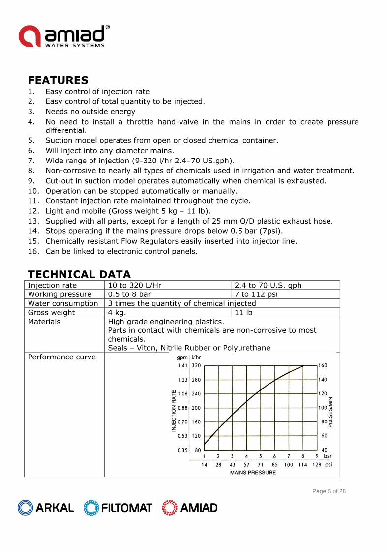
TECHNICAL DATA Injection rate 10 to 320 L/Hr 2.4 to 70 U.S. gph
Working pressure 0.5 to 8 bar 7 to 112 psi
Water consumption 3 times the quantity of chemical injected
Gross weight 4 kg. 11 lb
Materials High grade engineering plastics. Parts in contact with chemicals are non-corrosive to most
chemicals. Seals – Viton, Nitrile Rubber or Polyurethane
Performance curve

Page 6 of 28
GENERAL DESCRIPTION (FIG.1)
a. Reciprocating water
motor & pump assembly
(Part No. 19)
The reciprocating type motor in the cylinder housing (No.20)
consists of two pistons and a main pilot valve. The pump, which is
connected to the motor body, draws the chemical from the tank or
container and injects it into the main pipeline.
b. Housing
(Part No. 20)
The housing, to which the injection accessories are connected,
Contains the motor and pump.
c. Automatic cut-out
(Part No. 11)
The start-stop knob (No.12) us an integral part of the automatic
Cut-out unit. The cut-out automatically stops operation of the
pump, when the level of the chemical drops below the level of the
suction head base (No.16). The automatic cut-out is only
operational with Suction Type 4-01.
d. Valves
(Parts No. 8,4,6)
Two valves are fitted into the discharge line and one valve is
mounted on the chemical intake line. Their functions are to
prevent water in the main line from entering the chemical tank and
to prevent the return discharge of chemical into the tank or
container.
e. Air-Release valve
(Part No. 5)
This is a manually activated ball valve for venting air from the
system, generally, during the initial operation. If as a result of a
water stoppage, sub-pressure is formed in the main line, the ball
in the Air-Release valve will automatically open the escape vent
and the line will be vented into the atmosphere. This arrangement
ensures that siphoning of the Air-Release valve is available to be
used with sequential and automatic operations.
f. Suction Head
(Parts Nos. 16-18)
The suction head consists of a weighted, round base plate (No.16)
And filer (No.17) containing a plastic ball (No.18). The Suction Head is only supplied with the suction type 4-01 (Cat. No. 300000-
000011).

Page 7 of 28
KEY: 1. Motor seal, large
2. Motor seal, small 3. Pump seal 4. Injection valve 5. Injection valve housing assembly incl. Air-
Release valve 6. Non-return valve 7. Chemical injection outlet
8. Inlet valve 9. Chemical inlet 10. Pilot line inlet
11. Automatic cutout 12. Start-stop knob 13. Drive water inlet
14. Exhaust water outlet 15. Motor main valve 16. Suction head base plate 17. Suction head filter 18. Plastic float ball 19. Motor and pump assembly 20. Housing
21. Motor air vent 22. Pilot line – cutout 23. Bearing disc 24. Injection valve spring NOTE: VALVES AND SPRINGS If the valves are removed from the injector-
special care must be taken to return them so they face the correct direction as in Fig. 1. Please note that only the Injection valve No.4 is fitted with a spring. Please take care when refitting the spring and be sure that it sits completely inside the
four legs of the valve.

Page 8 of 28
PRELIMINARY PREPARATIONS FOR INSTALLATION Types 4-01 (300000-000011) & 4-02 (300001-000011)
WARNING
UNDER NO CIRCUMSTANCES IS A WATER SYSTEM, CONTAINING OR HAVING CONTAINED CHEMICALS, BEING DIRECTLY CONNECTED TO A DRINKING
WATER SYSTEM.
THE MANUFACTURER WILL NOT BE RESPONSIBLE FOR INCORRECT ASSEMBLY OR MISUSE OF THE INJECTOR.
It is highly recommended to install the water drive hand-valve after main filtration. Before attaching
the pump to the system, install two ¾” hand valves on the main water line. These valves must be
located at lest 50 cm apart. An upstream valve (1) will supply the drive water to operate the pump
motor. A chemical solution will be injected into the system through valve (8) downstream.
Installation of the two filters, supplied with the pump, is indispensable for the protection of the valve
assemblies and the pump motor. The first filter (3) (100 micron) in the drive water line prevents dirt and
sand from entering the motor, thereby permitting smooth and steady operation. The second filter (5)
(300 micron) in the chemical suction or feed line, prevents particles from entering the valve assemblies
and jamming them in an open or closed position.
The installation of a check valve, in the mains between the two hand valves, is advisable. This will
prevent circulating chemical-laden water operating the pump.
A length of 25 mm O/D (3/4" I/D) thin-walled plastic pipe should be fitted to the injector exhaust outlet
(9), in order to lead away the exhaust drive water to a convenient place. The exhaust pipe should not be
restricted and it should be installed level or downwards.

Page 9 of 28
INSTALLATION AND OPERATION SUCTION TYPE 4-01(300000-000011) INJECTION FROM CONTAINER
KEY: 1. Drive water hand valve 2. End connector 3. Filter
4. Automatic cut-out 5. Suction head 7. Air-release valve 8. Injection line hand valve 9. Water exhaust 10. Check valve (optional)
a. Hang the pump, with the sling provided, at a convenient height on a post made of 1" galvanized
pipe. Do not hang it below the solution level of the container.
b. Connect the drive water line (through the 1"C filter supplied) to the mains by means of the union
coupler.
c. Connect the injection line by means of the second union coupler downstream from the drive water
coupler.
d. Place the suction head in the chemical container and ensure that it stands upright.
e. Fully open the hand valve between the injection line and the main water line.
f. Open the drive water hand valve and pull out the knob on the automatic cut-out. The motor will
start operating.
g. To prime the pump, press the air release valve cap until all the air is expelled and chemical is
ejected from the air release valve. There will be reduction in the motor speed when the pump starts
operating. If an automatic air release valve is fitted there is no need to prime the pump.
h. The rate of chemical injected can be adjusted by throttling the injection line hand valve or by using
flow regulators (see pages 12-14).
NOTE: Suction type 4-01 (300000-000011) can be converted to Gravity Feed type 4-02 (300001-000011) by
means of a conversion kit Cat. No. 700190-003307 Note that the kit does not include an NC Hydraulic
cut-out.
IMPORTANT:
The suction type injector should be washed out after use, by placing the suction head in a container of clean water and pumping for 50-100 strokes.
Injector Unit
Fertilizer
Solution
Water Mains
9
10
5
8
3
1
2
4
7

Page 10 of 28
INSTALLATION AND OPERATION GRAVITY FEED TYPE 4-02 (300001-000011) KEY: 1. Drive water hand valve 2. Drive water filter 3. Chemical supply filter 4. Automatic cut-out (NC Hydraulic valve) 5. Anti-siphon valve
6. Air release valve 7. Injection line hand valve 8. Water exhaust
9. Check valve (optional) 10. End connector
a) The anti-siphon valve should be placed at a height above the surface of the fertilizer solution, with
the valve outlet pointing upwards.
b) Hang the pump on a 1" galvanized pipe post near the tank at a convenient height using the
provided sling.
c) Connect the chemical feed line to the tank by means of the union coupler supplied.
d) Connect the end of the injection line to the closed chemical injection hand valve.
e) Connect the drive water line (with the 1"C filter) to the water mains by means of the union coupler.
f) Open the chemical tank outlet hand-valve.
g) Open drive-water hand valve.
h) When pressure is built up in the injection line, the anti-siphon valve closes and the pump will stop
operating.
i) Open the injection line hand valve on the irrigation mains and the pump will operate normally.
j) There are two ways to connect the N.C. valve to the injector, depending on how it is to be used:
1. When using the injector without a computer: The injector is ready for use (with constant
pressure command to the N.C. Hydraulic valve). In this way operation is allowed without a
computer or any controller.
2. When operating with a computer/controller: Should the injector work with a computer or a
controller, the side port of the N.C. valve should be plugged and a pilot tube from the controller
solenoid should be connected to the command connector of the valve.
k) The injection rate of chemicals can be adjusted by throttling the injection line hand valve or by
using Flow Regulators (see pages 12-14), see injection formula at beginning of manual.
IMPORTANT: The Gravity-Feed type should be rinsed through by placing the chemical feed inlet (adjacent to the blue
filter) in clean water and pumping as above.
TANK
4
1
2
38
9
6
10
7
5
Page 11 of 28
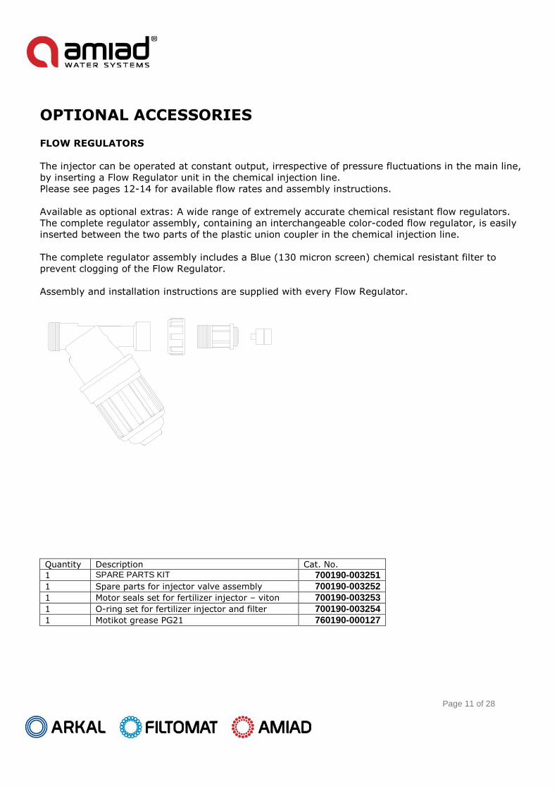
OPTIONAL ACCESSORIES FLOW REGULATORS
The injector can be operated at constant output, irrespective of pressure fluctuations in the main line,
by inserting a Flow Regulator unit in the chemical injection line.
Please see pages 12-14 for available flow rates and assembly instructions.
Available as optional extras: A wide range of extremely accurate chemical resistant flow regulators.
The complete regulator assembly, containing an interchangeable color-coded flow regulator, is easily
inserted between the two parts of the plastic union coupler in the chemical injection line.
The complete regulator assembly includes a Blue (130 micron screen) chemical resistant filter to
prevent clogging of the Flow Regulator.
Assembly and installation instructions are supplied with every Flow Regulator.
Quantity Description Cat. No.
1 SPARE PARTS KIT 700190-003251
1 Spare parts for injector valve assembly 700190-003252
1 Motor seals set for fertilizer injector – viton 700190-003253
1 O-ring set for fertilizer injector and filter 700190-003254
1 Motikot grease PG21 760190-000127

Page 12 of 28
FLOW REGULATOR WITH SUCTION TYPE INJECTOR 4-01(300000-000011)
Assembly instructions:
1. Open the union coupler at the end of the chemical
injection pipe. See pictures 1&2.
2. Connect he flow regulator filter to the injection pipe.
Ensure the arrow on the filter is in the chemical flow
direction (see picture 3).
3. Insert the flow regulator capsule into the empty check
valve so the projection on the face of the capsule points
towards the filter. (See picture 3).
4. Connect the flow regulator housing to the union coupler
attached to the flow regulator filter. (See picture 4).
5. To change the capsule – open the union coupler
containing the capsule. Slightly open the injector hand
valve. The water line pressure will eject the capsule.
Close the control valve, insert the capsule required and
rejoin the union coupler.

Page 13 of 28
FLOW REGULATOR WITH GRAVITY FEED INJECTOR 4-02 (300001-000011)
Assembly instructions:
1. Open the check valve at the end of the
chemical injector pipe. See picture 1.
2. Remove the valve installed from its place
and insert into the inlet of the flow
regulator filter. (See picture 3).
3. Connect the flow regulator filter to the
injection pipe and make sure that the
arrow on the filter is in the direction of
chemical flow. (See picture 3).
4. Insert the flow regulator capsule into the
empty check valve so the projection on
the face of the capsule point towards the
filter. (See picture 3).
5. Connect the flow regulator housing to the
union coupler attached to the flow
regulator filter. (See picture 4).
6. To change the capsule, open the union
coupler that contains the capsule. Slightly
open the injector hand valve. The water
line pressure will eject the capsule. Close
the control valve, insert the capsule required and rejoin the union coupler.

Page 14 of 28
3/4" N.C. "NORMALLY CLOSED" HYDRAULIC VALVE (300004-000003)
Wide variety of applications: For chemical liquid fertilizer
and water flow control.
Fully chemical resistant: Plastic components and viton
seals guarantee corrosion-free operation with all liquid
chemicals and water.
Water or air operated pilot system: The pilot system is
completely separated from the valve itself thereby allowing
the flow of expensive liquids to be controlled by pressurized
water.
No need for outside source of energy: Operates from
water mains supply.
Valve closes with pilot pressure: The "normally closed"
feature ensures that if the pilot water pressure drops due to
main pump shut-down to control system malfunction or pilot tube damage the valve will close
automatically.
Operates in high pressure systems: Maximum working pressure up to 10 bars (140 psi)
Choice of flow directions: The valve can be installed with 1 inlet and 1 or 2 outlets or with 2 inlets
and 1 outlet.
Easy to install: Simple installation by means of the Amiad union connector (Raccord). Unlimited
number of valves can be screwed together forming a valve manifold.
Wide range of uses:
Control opening and closing of spraying and fertilizing systems.
Allocate liquid chemicals to spraying and spraying according to a pre-set command.
Allocate several liquids from different sources simultaneously to one or more outlets.
PRESSURE TABLE PRESSURE LOSS TABLE
WORKING PRESSURE PILOT PRESSURE FLOW RATE PRESSURE LOSS
m. psi m. psi l/m Usgph Imp.gpm m. psi
10 14 4.5 6 10 2.6 2.2 0.4 0.6
40 57 9.0 13 20 5.3 4.4 1.2 1.7
80 114 14.0 20 30 7.9 6.6 3.0 4.2

Page 15 of 28
AIR RELEASE VALVE
1. To release air from fertilizer system on initial start.
2. Prevent siphon suction after the fertigation finished by ventilating the system.
It is recommended to periodically check that the valve moves freely in it seat.
DO NOT install a spring under this valve.
INJECTOR CONTROLS
Injection flow rate
The injection rate can be controlled by throttling the chemical injection hand control valve, for hand
irrigation only, use a chemical resistant ball valve, with a stiff action or other type hand valve with a
locking device.
Variations in chemical flow are to be expected when regulating by hand valve.
Chemical injection rate formulae are found on page 3 of this manual. Twice the number of
pulses/min. Give the injection rate in liter/hr. Other formulae are given for flow rates in both imp.
and U.S. gph.
Automatic dosage
The total quantity of the injected chemical can be controlled in the following ways:
a) For the Suction type only: Fill the container with the required amount of the chemical and place
the suction head on the bottom of the container, or alternatively suspend the suction head in the
container at such a height, so that the liquid above the base of the suction head, is the required
quantity to be injected.
b) The suction and gravity feed type: By installing a water metering valve to exactly 3 times the
required quantity of chemical to be injected, Please note that this method is far from being accurate
the water meter is not designed for pulse operation.
c) Use an Irrigation computer for Dosage or Proportional Fertigation.
NOTE: When flow regulators are installed, method b) is not recommended.

Page 16 of 28
MAINTENANCE
It is recommended to replace the two motor seals, pump seal and bearing disc every season.
NOTE:
To keep the pump in good working condition, it should be lubricated with the recommended grease
every 200 hours or depending on frequency of use and water pressure.
For the injector lubrication use industrial silicon white grease
a. Stop pump operation by pressing the start-stop
knob or close the hand-valve.
b. When operating with gravity feed, close the
chemical tank outlet hand-valve.
c. Disconnect the exhaust pipe from the pump.
d. Unscrew the cylinder housing cap. (See Fig. 9)
e. Removing the cap will reveal the main control
valve (a round rod with holes on the tip).
f. Pull the valve gently. Pull out the start-stop
knob or open the hand-valve (Fig.10). The drive
water will eject the motor form the cylinder
body.
Press start-stop knob to stop the drive water or
close the hand-valve.
g. Thoroughly clean and dry the motor unit and then lubricate the tree seals with the Silicon grease
provided
h. Slide the motor back into the cylinder housing after emptying it of water. Take care that the
Bearing Disc is returned with the colored side inwards.
i. Screw on the body cap and reconnect the exhaust pipe to the pump. The pump is ready for
operation.
When replacing the pump seal – thoroughly dry and clean the pump seal seat before replacing.

Page 17 of 28
GREASING THE FERTILIZER INJECTOR
MOLIKOT PG-21 is advanced Silicon grease that
was examined and found ideal for the lubrication of
Amiad Injectors.
Greasing the fertilizer injector is part of its
routine standard maintenance requirements.
The frequency of the greasing depends on the
drive water quality and pressure, the fertilizer
quality and the injector mechanical condition.
The injector should be lubricated whenever
reductions in its efficiency and /or friction noises
are recognized.
Applying instructions:
1) Clean and dry the injector piston.
2) Apply a thin layer of grease on all three piston seals as shown in the drawing.
3) Verify that the Injector Cylinder is clean.
4) Insert the lubricated piston into the cylinder, mind not to band the seal edge while pushing the
piston into the cylinder.
Please use only MOLIKOT PG-21 for lubricating the injector pumps.
A tube of grease can be found in each new injector box.

Page 18 of 28
TROUBLE SHOOTING
The following trouble shooting table will help you to locate and solve most of the trouble that may
occur during fertigation.
The table is made of three columns.
a. Fault-as they appear in the field
b. Possible cause – there is more than one possible cause to a fault; the possible cause is marked by
its probability.
c. Checking & trouble shooting – explains how to find the fault and how to fix it step by step.
Replacement parts:
Can be obtained in readymade sets of parts of a specific group (i.e. motor seal set)
FAULT POSSIBLE CAUSE CHECKING & TROUBLE SHOOTING
A. MOTOR
1. Motor is not
working
1. Drive water malfunction Check opening of pump cutout, hand
Regulating valve and/or water line.
Check that the 155 mesh=0.1 mm filter on
The drive water line is clean.
Check that water reaches motor:
a. Press star-stop knob
b. Open cylinder housing cap.
c. Take out motor and pump assembly (see
Fig.10)
2. Defective motor seals Visually check condition of pump and motor
Seals.
3. Main motor valve
jammed
Check movement of main control valve for
smoothness, free forward and backward.
4. Breaks or cracks 1. Visually check for breaks or cracks in
assembly.
2. Empty cylinder housing and replace
assembly with cutout closed.
3. Open drive water.
5. Restriction in the
Exhaust Hose or
Exhaust Hose installed
upwards
1. Visually check Exhaust hose.
2. Press Air Release Valve – Pump operates by
ejecting chemical through Air Release Valve.
3. Remove restriction and/or point Exhaust
Hose downwards.
6. Blockage in Chemical
injection line
1. Press Air Release Valve
2. If Injection starts from the air release
valve, check non-return valve, chemical line
or injection line hand valve.

Page 19 of 28
FAULT POSSIBLE CAUSE CHECKING & TROUBLE SHOOTING
2. Motor works
slowly and with
difficulty
1. Defective seal Check assembly as above
2. Mechanical
interference
in control valve
movement
3. Seals lack grease Lubricate pump and motor seals with
recommended grease
4. Drive water blockage Check drive water and filter.
5. Exhaust hose
restricted
See A.1.5
3. Motor vibrates
and works
irregularly
1. Interface in suction
system
1. Check if suction filter is clean
2. Check that suction head ball is not stuck in
the base.
3. Check if the 25mm exhaust pipe if too
long.
FAULT POSSIBLE CAUSE CHECKING & TROUBLE SHOOTING
B. PUMP & VALVE SYSTEM
Motor works well
but does not pump
chemical after
venting air via Air-
release valve
1. Defective pump seal Remove motor assembly and visually check
the pump seal.
2. Defective injection
valve
Remove pipe from air-release and start
pump; touch valve opening lightly. If suction
is felt, injection valve is not working. Remove
and check.
3. Jammed or defective
suction valve
Open inlet valve:
a. Check smooth movement of valve
b. Remove valve and visually check seals
4. Gravity feed: Air in
fertilizer injection line
Vent air as per operating instructions
FAULT POSSIBLE CAUSE CHECKING & TROUBLE SHOOTING
C. STOPPAGE – SUCTION PUMPING
1. Spring
resistance on
pressing start-
stop knob which
reopens by itself.
1. Air trapped in pilot
tube to cutout.
1. Disconnect cutout pilot tube. Pressing knob
will then stop flow.
2. After reconnecting pilot tube, check that
there is no sag where water may collect
and interfere with free airflow.
2. Cut-out closes
although suction
head immersed
in liquid.
1. Clogged filter screen
causing ball to drop
on base vent.
1. Wash and clean filter screen.
2. Viscous fluid cannot
pass through screen
causing ball to drop to
base.
1. Change filter screen to larger perforation.

Page 20 of 28
PARTS CATALOG
SUCTION HEAD ASSEMBLY – TYPE 4-01 (700190-003301)
Ref. Description Cat. No.
1 Suction base assembly 700190-003317
2 Plastic ball 770104-000186
3 Filter screen element, 50 mesh 710101-000512
5 Coupler for 20mm pipe 700190-003256
6 Pilot tube 6x10 (2.4 m.) 700190-003302
7 Toothed clamps x6 760108-000095
8 Connector 20mm 780101-000738
9 Suction pipe 1/2" (2 m.) incl. fitting 700190-003291

Page 21 of 28
DRIVE WATER PIPE & FILTER (4-01 & 4-02)
Ref. Description Cat. No.
1 Drive water pipe for 4-02 700190-003294
1 Drive water pipe for 4-01 700190-003296
2 1"C Filter, 100 micron (155 mesh) 011001-000001
3 Filter housing 3/4" 710101-000478
4 O-Ring (34 x 2.15) 770102-000099
5 Nylon screen - complete, 100 micron 710101-000462
6 O-Ring (50 x 3 ) 770101-000039
7 Filter head 1"-Compact 710101-000452
8 Union seal (viton) 770102-000225
9 Connector 3/4" 700190-003316
10 Union nut 710101-000986
12 Nipple for 16mm pipe incl. seal 700190-003314

Page 22 of 28
CHEMICAL INJECTION PIPE
Ref. Description Cat. No.
Injection pipe for 4-02 (4m.) 700190-003287
Injection pipe for 4-01 (2m.) 700190-003289
1 Pipe 3/8" (Transparent) 790208-000005
2 Coupler for 16mm pipe 710101-000990
3 Connector 16mm 780101-000739
4 Union Nut 710101-000986
5 Nipple-16mm (incl. seal - viton) 700190-003287

Page 23 of 28
UNIT ASSEMBLY
Ref. Description Cat. No.
1 Cylinder housing 700190-003258
2 Connector 1"-3/4" 710101-000985
3 Valve (incl. seal) 700190-003318
4 Valve seal (viton) 770103-000101
5 Union seal (viton) 770102-000225
6 Coupler for 16 mm pipe 700190-003255
7 Nipple-16 mm (incl. seal - viton) 700190-003314
8 Union nut 710101-000986
9 Cap 16mm 780101-000739
10 Coupler for 20mm pipe 700190-003256
11 Nipple - 20mm (incl. seal - viton) 700190-003315
12 Cap 20mm 780101-000738
13 Injection valve spring (0.7) 760107-000060
14 Injection valve housing assembly (black) 700190-003305
15 Injection valve housing assembly (blue) 700190-003306
18 Cap 710101-000977
19 Stainless steel sling 710103-004425
22 Stainless steel nut UNC 1/4" 700102-000366
23 Stainless steel bolt - 1/4" X 1/2" 760101-000423
24 Clamp - upper half 710101-000971
25 Clamp - lower half 710101-000972
26 or
27
Cut-out standard
3/4" NC hydraulic valve (cut-out)
700102-000366 700190-003248
28 Motor & pump assembly - complete 700190-003249
29 Cap seal 770102-000074
30 Cylinder body cap 710103-004196
31 Connector 25mm x 1"-female 780104-000498
32 Bearing disc 700190-003313
33 Motor seal large 710101-000962
34 Motor seal small 710101-000961
35 Pump seal seat 710101-000968
36 Pump seal (viton) 770104-000179
37 Pump seal (rubber) 770105-000001
38 Valve retaining ring 710101-000987
39 Union nut clip 710101-000974

Page 24 of 28

Page 25 of 28
UNIT ASSEMBLY – GRAVITY FEED TYPE 4-02
Ref. Description Cat. No.
1 Automatic air release Assembly 700190-003299
2 Anti-siphon valve 700190-003304
3 Pipe 3/8"-(4m) incl. fittings 790208-000005
4 Check valve and nipple 3/4" 700190-003310
5 Pipe 3/8"- (4m) incl. fittings 700190-003287
6 Pipe 1/2"- (2m) incl. fittings 700190-003293
7 1"C Filter, Blue, 30 mesh 010001-000051
8 Union nut 710101-000986
9 Connector 3/4" 700190-003316
10 Drive water pipe 700190-003294
11 Injection valve housing assembly (Blue) 700190-003306
12 1"C Filter, 155 mesh (Black) 011001-000001
13 Air release pipe 8/12 (transp.-60cm) 700190-003300
14 3/4" NC hydraulic valve (cut-out) 700190-003248
Page 26 of 28
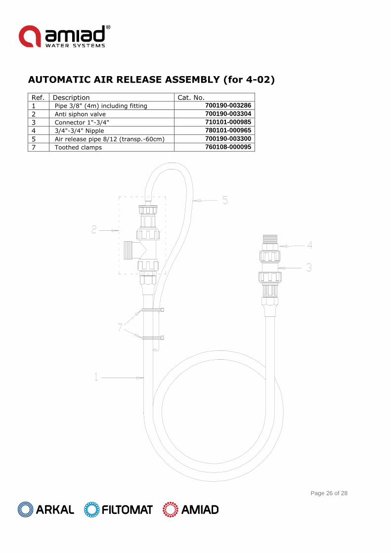
AUTOMATIC AIR RELEASE ASSEMBLY (for 4-02)
Ref. Description Cat. No.
1 Pipe 3/8" (4m) including fitting 700190-003286
2 Anti siphon valve 700190-003304
3 Connector 1"-3/4" 710101-000985
4 3/4"-3/4" Nipple 780101-000965
5 Air release pipe 8/12 (transp.-60cm) 700190-003300
7 Toothed clamps 760108-000095

Page 27 of 28
FLOW REGULATOR ASSEMBLY WITH FILTER
Ref. Description Cat. No.
Flow regulator assembly (incl. 1 capsule)
700190-003271
700190-003272
700190-003273
700190-003274
700190-003275
Flow regulator ass. (incl. 5 capsules) 700190-003270
1 Flow regulator assembly filter 700190-003269
2 Flow reg. capsule 10 l/hr (incl. 0-ring) 700190-003263
3 Flow reg. capsule 20 l/hr (incl. 0-ring) 700190-003264
4 Flow reg. capsule 40 l/hr (incl. 0-ring) 700190-003265
5 Flow reg. capsule 60 l/hr (incl. 0-ring) 760108-000095
6 Flow reg. capsule 80 l/hr (incl. 0-ring) 700190-003267
7 Capsule 0-ring (viton) 770102-000224
8 Union seal (viton) 770102-000225
9 Connector 3/4" 700190-003316
10 Union nut 710101-000986
11 Blue filter head 700190-001168
12 O-Ring (Viton 50 x 3) 770102-000237
13 Seal (viton) - cylinder 770101-000068
14 Cylinder 120 mesh for blue filter 700101-000284
15 Blue filter housing 710101-000450
16 1"M-3/4"F Thread filter, Blue, 130 micron (120 mesh) 010001-000053

Page 28 of 28
ADDITIONAL ITEMS FOR FERTILIZER INJECTOR
Ref. Description Cat. No.
Spare parts kit for fertilizer injector 700190-003251
Set of seals for fertilizer injector 700190-003252
Set of piston seals - viton 700190-003253
Set of O-rings for fertilizer injector 700190-003254
Motor & pump assembly - complete 700190-003249
Instructions manual - English 760108-000095
Instructions manual - Spanish 910101-000316
Fertilizers & Chemical Injectors, amiadwww.irrigationglobal.com
Contact us for suppport and orders, click here >