ammonia storage tank pre -commissioning...nitrogen purging is the very important activities before...
TRANSCRIPT

Ammonia Storage Tank Pre -Commissioning
Prem Baboo DGM (Production & process)
Abstract:- In Fertilizers Industries surplus ammonia is stored in a large capacity tank. For efficient discharge and storage of hazard
chemicals such as ammonia, special processes must be developed, and several related parameters must be checked and evaluated. The
Nitrogen purging is the very important activities before taking ammonia in the storage tank and purging aim to reduce the Oxygen
content in the tank below the lower flammable limit that is 16%, during the purging the tank may be exposed to conditions which
could cause damage. This is the process whereby a safe atmosphere is established within the process equipment. Therefore extreme
care was taken to prevent over pressurizing the tank or subjecting it to thermal stress beyond its design. The purging is carried out
until the Oxygen Concentration of <8.0 % is reached. In this article hydraulic test and pneumatic test final settlement of the tank were
studied, pressure changes in ammonia storage systems that are purged by nitrogen gas, during filling by Nitrogen purging, the
amount of Nitrogen were calculated.
Keywords:- Ammonia storage, Purging Ammonia Nitrogen, Cryogenic, ammonia pump, Vaporiser, Oxygen analyser, foundation levelling
settlement.
INTRODUCTION
Dangote Fertilizer Project consists in the realization of an Ammonia and Urea complex with associated facilities. The Project
under progress at LEKKI Free Zone in Ibeiju-Lekki Local Government Area of Lagos State, Nigeria.
Ammonia and Urea complex includes:
2x2200 MTPD Ammonia Trains based on HTAS technology (and BASF technology for CO2 capture in Ammonia Plants).
2x3850 MTPD Melt Urea Trains based on Saipem Technology.
2x3850 MTPD Urea Granulation Trains based on Udhe Fertilizer technology. Associated Utility Units.
For ammonia storage 20000MT capacity double wall tank is installed for train-1 & train -2.
AMMONIA STORAGE BRIEF DESCRIPTION
In ammonia Plant ammonia is produced from synthesis gas containing hydrogen and nitrogen in the ratio of approximately
3:1.Besides these components, the synthesis gas also contains inert gases such as argon and methane to a limited extent. The
source of H2 is demineralized water (steam) and the hydrocarbons in the natural gas. The source of N2 is the atmospheric air. The
source of CO2 is the hydrocarbons in the natural gas feed. Product ammonia and CO2 is sending to urea plant. The main function
of the plant is illustrated in the figure-1
Fig.-1
International Journal of Engineering Research & Technology (IJERT)
ISSN: 2278-0181http://www.ijert.org
IJERTV8IS090209(This work is licensed under a Creative Commons Attribution 4.0 International License.)
Published by :
www.ijert.org
Vol. 8 Issue 09, September-2019
612

Ammonia Storage System mainly covers the requirements of Liquid Ammonia Storage, transfer of liquid ammonia and
ammonia vapour from/to Ammonia-Urea Plants, Storage Refrigeration and Flaring of Ammonia Vapours during emergency
conditions. The unit includes the following functional sections:
1. Ammonia Storage Tank (30-T-01)
2. Transfer of Liquid Ammonia from Ammonia plants to Urea plants by Ammonia
Process transfer pumps (30-P-01).
3. Transfer of Ammonia Vapour to Ammonia Plants by Ammonia Vapour
Displacement Blower (30-U-01)
4. Ammonia Stand-by Refrigeration Package (30-PK-02)
5. Ammonia Storage Flare (30-PK-01)
6. Ammonia Drainage Pit (30-CB-01)
Liquid ammonia is transferred from Ammonia Units (Train 1 or 2) to the Ammonia Storage Tank. Details of the tank as
follows:
Ammonia storage Tank Sr. No. Name of Items Value
1 Number of Tank 1
2 Capacity 20000 MT of Liquid Ammonia
3 Operating Pressure, in/Max 200/400 mm H2Og
4 Operating Temperature -33 0C
5 Max daily Boiled- off 0.04% by weight of full storage capacity
6 Ammonia Transfer pump Capacity 148.4 m3/h
Table-1
Ammonia Vapour Displacement Blower is designed to transfer the ammonia vapour generated from Ammonia Storage tank to
Ammonia Plants. In normal operation the excess ammonia vapour is sent to the Ammonia Process Plant by means of Ammonia
vapour displacement blower for further recovery in the main Process Refrigeration Unit. In case such routing is not possible, or
in case of pressure rise in the ammonia storage tank above the normal operating range, the excess ammonia vapours are
compressed and condensed by the dedicated Ammonia Stand-by Refrigeration unit. The maximum capacity of the Blower the
design flow-rate of 800 Nm3/which is equivalent to 610 kg/ammonia Stand-by Refrigeration Package The ammonia
refrigeration package is to maintain at ‐33°C the liquid ammonia contained in the Ammonia Storage Tank. In case the pressure
in the ammonia Storage Tank rises above the normal operating value, the ammonia vapours are sent to the Ammonia Storage
Stand‐by Refrigeration Package .where they are compressed and condensed and then sent back to the Ammonia Tank .The
Package is composed of the following main items: Screw compressor, oil separator, Oil Cooler, Condenser, liquid receiver,
economizer and saturator. The operating ammonia flow rate is 780 kg/h. The package is designed for an ammonia flow rate of
860 kg/h at maximum load.
AMMONIA STORAGE FLARE.
Ammonia Storage Flare is dedicated to Ammonia storage section and it is sized considering the worst scenario of the system,
i.e. Ammonia BOG Compressor Blocked Outlet condition with a Blow-down Gas flow-rate of 1132 Nm3/h (860 kg/h), LHV of
Blow down gas is 3375 Kcal/Nm3.The maximum consumption of Fuel Gas necessary to assist the complete combustion of the
ammonia gas, discharged at the said flow rate is minimized. The estimated consumption of fuel gas is 130 kg/h, during the
emergency flaring of the design stream. The Total height of the stack is 15 meter, Stack diameter 10”and stack design pressure
is 3.5 kg/cm2.
The Ammonia Storage Tank is double containment, designed and constructed so that both the primary and secondary self-
supporting containers shall be capable of independently containing the stored liquid. Both inner & outer tank walls and bottoms
are made of low temperature materials and are designed for product deriving loads. Since the insulation system is outside the
outer tank, both inner and outer tank operate at product temperature, resulting in minimum product flash in the event of a
product spill into the outer tank. The secondary containment structure is independent from that of the primary tank. Ammonia
storage tank is equipped and provided with the necessary instrumentation capable of monitoring and controlling both normal
operation and emergency occurrences, while assuring the highest reliability and operability. Ammonia Storage Tank is provided
with pressure relief valves and with vacuum relief valves adequate to manage any emergency. Furthermore the tank is provided
with nitrogen line and distribution ring at tank bottom; nitrogen will be used for purging operations on the tank prior to
introduce ammonia, distribution ring to be used during tank cool down; nitrogen is also used to avoid vacuum, in case of
unforeseen operations.
Inner Tank-The inner tank shall be full integrity, self-supporting, open top with suspended deck (insulation installed on the
suspended deck), with dome roof (umbrella type).The inner tank is made up of steel suitable for the design temperature and
designed in accordance with the required standards.
International Journal of Engineering Research & Technology (IJERT)
ISSN: 2278-0181http://www.ijert.org
IJERTV8IS090209(This work is licensed under a Creative Commons Attribution 4.0 International License.)
Published by :
www.ijert.org
Vol. 8 Issue 09, September-2019
613

Sr.No. Parameters Value
1 Working Capacity 29370 m3,or, 20000 MT
2 Dimension, ID/H 38 meter/28.2 meter.
3 Operating Pressure Min/Max 200/400 mm H2O
4 Design Pressure vacuum -50 mm Hg
5 Design Pressure 1500 mm H2O
Table-2
Outer Tank-The outer container (bottom + wall) are designed in accordance with the API Standard requirements and able to
contain the entire liquid content in case of inner tank leak. It shall be vapour tight type and externally insulated. The annulus
between the internal and external wall is covered to prevent rain water entrance into the annular space.
Liquid ammonia from Ammonia Plant (Train 1 or 2) can be transferred to the Ammonia Storage Tank through ammonia transfer
line (8 inch). The same ammonia transfer line (8 inch) can be used to transfer the cold ammonia from Storage Tank to Urea
Plant (Train 1 or 2) through the Ammonia Process Pump during upset of any one of the ammonia plants. Liquid ammonia is
transferred to Urea Plants at following conditions:
Sr. No. Parameters value
1 Normal Flow rate 91.67 T/H
2 Design Flow rate 100 T/h
3 Temperature -330C
4 Operating Pressure 27 kg/cm2
Table-3
NITROGEN REQUIRED FOR AMMONIA STORAGE TANK PURGING
Nitrogen purging is easily adapted to any process installation. Different methods are used depending on the type and shape of
the equipment to be purged and on the location of the purging inlets and outlets. Two operations involve replacement of inert
gas in tanks, namely:
(a) Dilution, which is a mixing process;
(b) Displacement, which is a layering process.
In each of these replacement operations, one of two processes can predominate. These two processes have a marked effect on
the method of monitoring the tank atmosphere and the interpretation of the results .The dilution theory assumes that the
incoming inert gas mixes with the original gases/vapours to form a homogeneous mixture throughout the tank vapour space; the
result is that the concentration of the original gas/vapour decreases exponentially. In practice, the actual rate of gas/vapour
replacement depends upon the volume flow of the incoming inert gas, its entry velocity and the dimensions of the tank vapour
space. For complete gas/vapour displacement, it is important that the entry velocity of the incoming inert gas be high enough for
the jet to reach the full vapour space; it is therefore important to confirm the ability of every installation using this principle to
achieve the required degree of gas replacement throughout the tank vapour space. We can calculate moles of gas in ammonia
storage tank and start and end, and assume this difference came from the nitrogen tank. Note you must use absolute temperature
in kelvins (add 273.15) and ammonia storage tank pressure (add typical atmospheric pressure of 1.01 bar) for all temperature
and pressure.
At end of cycle, moles of gas nf = (1/R)*Pf*Va/Tf
At start of cycle, ni = (1/R)*Pi*Va/Ti
The gas from the nitrogen tank nt = nf - ni,
but its volume is given (at tank pressure and temperature) by V = nt*R*Tt/Pt
Substituting, the gas constant cancels out yielding
Vt = (Tt/Pt) * Va * (Pf/Tf - Pi/Ti)
Where, i and f subscripts denote initial and final conditions in Ammonia storage tank, t for tank conditions (or the pressure and
temperature you want the nitrogen volume stated at. Va is the volume of the ammonia tank, reduce for volume occupied by the
parts. We assumed atmospheric conditions for Nitrogen tank.
Va=40766 m3, P=0.381 bar, Ti=298.75,Pf=1.093 bar,
We get Vt = (298.75 /0.381) * 40766 * (1.093/340.35 – 0.393 /298.75)
(784.120)*40766*(0.003251-0.000131)
(784.120)*40766(0.003119)
Vt = 101969.74 m³
Hence the nitrogen required for purging is 101969.74 m3
We get Vt = (298.75 /0.381) * 40766 * (1.093/313.35 – 0.393 /298.75)
(784.120)*40766*(0.0034881-0.000131)
(784.120)*40766(0.0033357)
Vt = 107311.74 m³
International Journal of Engineering Research & Technology (IJERT)
ISSN: 2278-0181http://www.ijert.org
IJERTV8IS090209(This work is licensed under a Creative Commons Attribution 4.0 International License.)
Published by :
www.ijert.org
Vol. 8 Issue 09, September-2019
614

NITROGEN PURGING OF AMMONIA TANK
Sr. No. Date Pressure of
Tanker
Evaporator outlet
Pressure
Pressure Ammonia
storage inlet, Bar
Pressure inside
the Ammonia tank, bar
Oxygen Content
1 12-09-2019 7.1 4.4 2.4 0.071 20.80%
2 13-09-2019 7.0 4.3 2.3 0.078 19.70%
3 14-09-2019 7.4 4.7 2.7 0.065 18.30%
4 15-09-2019 7.3 4.6 2.6 0.079 16.80%
5 16-09-2019 7.3 4.6 2.6 0.070 15.60%
6 17-09-2019 7.1 4.4 2.4 0.069 14.80%
7 18-09-2019 7.5 4.8 2.8 0.069 13.80%
8 19-09-2019 7.4 4.7 2.7 0.063 13.20%
9 20-09-2019 7.3 4.6 2.6 0.065 12.70%
10 21-09-2019 7.2 4.5 2.5 0.066 11.60%
11 22-09-2019 7.5 4.8 2.8 0.064 10.30%
12 23-09-2019 7.4 4.7 2.7 0.067 9.80%
13 24-09-2019 7.3 4.6 2.6 0.065 9.10%
14 25-09-2019 7.1 4.4 2.4 0.064 7.40%
Table-4
DISPLACEMENT PURGING
This method is used for equipment replacing the present air in the vessel. The volume of nitrogen required corresponds to the
physical volume of the vessel. The nitrogen volume required to purge equipment with a vessel is determined using the following
formula.-
V=Vo*P
Where V= Total Nitrogen volume required.
Vo=Water Volume of Tank (m3)
P=Absolute pressure of Nitrogen in the tank during the purging.
Hence the Required Nitrogen Volume=Vo * P
40766* 2.6=105991 Nm3
International Journal of Engineering Research & Technology (IJERT)
ISSN: 2278-0181http://www.ijert.org
IJERTV8IS090209(This work is licensed under a Creative Commons Attribution 4.0 International License.)
Published by :
www.ijert.org
Vol. 8 Issue 09, September-2019
615
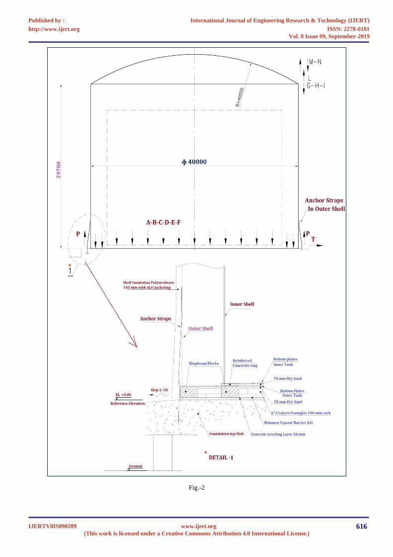
Fig.-2
International Journal of Engineering Research & Technology (IJERT)
ISSN: 2278-0181http://www.ijert.org
IJERTV8IS090209(This work is licensed under a Creative Commons Attribution 4.0 International License.)
Published by :
www.ijert.org
Vol. 8 Issue 09, September-2019
616

Initially rate was maintained higher about 1500-1600 Nm3/hr, but after 8 hrs. The rate was reduced after achieved the tank
positive pressure. The rate was maintained one third of the initial rate means the rate was about 300-400 Nm3/Hr. So time was
taken for total purging including mobilization purging operation and demobilization was 11-12 days completed. Since the
Nitrogen and air have similar specific gravity. The Nitrogen is expected to mix with air it enters the inner tank with complete
mixing in the tank, The Nitrogen quantity required to reduce the Oxygen Contents theoretically one time the tank volume about
40766 Nm3, apart from above the thumps rule the required volume of Nitrogen is 2.5 to 3.0 times of ammonia storage volume,
so roughly figure is 100000Nm3 to 110000 Nm3.
LIMITS OF EXPLOSIVE
The limiting oxygen concentration (LOC) is defined as the limiting concentration of oxygen below which combustion is not
possible, independent of the concentration of fuel. It is expressed in units of volume percent of oxygen. The LOC varies with
pressure and temperature. It is also dependent on the type of inert (non-flammable) gas being used. The limiting of the
concentration of oxidant in a fuel-oxidant-diluent mixture, below which an ignition. And/or subsequent deflagration cannot
occur, under specified conditions, may be achieved by maintaining an atmosphere that is inert in the vapour space of a container
or vessel. The addition of an inert diluent to a mixture of combustible material and oxidant affects the lower and upper
flammable limits and the limiting oxidant concentration. The figure below shows a typical flammability diagram that represents
a mixture of a combustible gas; an inert gas, Nitrogen; and an oxidant, oxygen at a given temperature and pressure. A mixture of
air (79 percent N2 and 21 present O2 by volume) and combustible gas is represented by the line formed by points DABE.As
shown in the figure-3. A given mixture of the combustible gas and air, whether ignitable or not, is specified by a point on this
line. Point A indicates the upper flammable limit of this mixture, and point B represents its lower flammable limit. Any point
within the area bounded by FBCAGF is in the flammable range and can be ignited.
Fig-3
Any point outside this area represents a mixture that cannot be ignited. Point C represents the limiting oxidant concentration to
prevent ignition; any mixture containing less oxygen cannot be ignited. Any mixture of oxygen and combustible gas alone is
represented by the left side of the triangle. Any mixture of Nitrogen and combustible gas alone is represented by the right side
of the triangle.
HYDRAULIC AND PNEUMATIC TEST OF AMMONIA STORAGE TANK
The hydraulic test, foundation settlement & pneumatic test were carried out from 06/8/2018 to 10/09/2018.The inner tank filling
rate was 1030 m3/hr(that correspond to 914 mm of depth per hour. During the filling of the tank the roof man hole was kept
open. The filling up of tank was executed in four steps. The settlement of foundation was checked in every step.
International Journal of Engineering Research & Technology (IJERT)
ISSN: 2278-0181http://www.ijert.org
IJERTV8IS090209(This work is licensed under a Creative Commons Attribution 4.0 International License.)
Published by :
www.ijert.org
Vol. 8 Issue 09, September-2019
617

Sr. No. Steps Filled level Equivalent height Hold time.
1 1st ¼ H 6940 mm 24 hrs.
2 2nd 1/2H 13875 mm 24 Hrs
3 3rd ¾ H 20810 mm 24 Hrs
4 4th H 27750 mm 48 Hrs
Table-5
FOUNDATION SETTLEMENT CHECKED
Foundation settlement was checked as per API 620.The value was recorded below table No-7
The level was taken corresponding to 8 points on outer tank wall. The bottom profile was checked 8 axes before hydrostatic &
pneumatic test the value recorded in table No.6
Position Location of different angles
0o 45o 90o 135o 180o 225o 275o 315o
Elevation(mm) 2150 2154 2140 2160 2158 2166 2149 2160
Deviation(mm) 2149 2154 2138 2164 2156 2160 2145 2149
Table-6
Load at Shell & Bottom
Sr.
No. Parameters Unit
Outer Tank Inner Tank
Erection Operating Hydro test Erection Operating Hydro test
1 Total Vertical Load KN 12203 227215 12203 6305 220628 321022
2 Design Internal Pressure KN/m2 .. .. 147100 .. .. ..
3 Test Internal Pressure m bar .. .. 183875 .. .. ..
4 Design External Pressure m bar .. .. -4900 .. .. ..
5 Liquid Pressure in Operating KN/m2 .. .. 171101 .. .. 188978
6 Liquid Pressure in Hydro test KN/m2 .. .. … .. .. 277500
Table-7
Fig-5
International Journal of Engineering Research & Technology (IJERT)
ISSN: 2278-0181http://www.ijert.org
IJERTV8IS090209(This work is licensed under a Creative Commons Attribution 4.0 International License.)
Published by :
www.ijert.org
Vol. 8 Issue 09, September-2019
618

PNEUMATIC TEST OF AMMONIA STORAGE TANK
After hydraulic test was completed, with the tank full of water at requested level, all roof shell nozzles were blinded and
tightened. Injection of air in the vapour space to the test pressure and equal to 1.25 times the design pressure (1500 * 1.25=1875
mm water column), in different steps of about 500 mm WC each with a holding time of about 15 minutes each. The pressure
was hold at least one hour. In order to allow an inspection of the tank of sign of distress. The pressure was slow released until
design pressure (1500 mm water column).Visual examination was carried out of all joints of the wall. Welding joints around
man ways and other connections. While the latter pressure was hold (1500 mm WG).a solution film was applied to all the
welding on the external of the roof including compression ring and nozzles. The weld joints of outer tank were tested with
solution film examination, as well.
CHECKED OF PSV.
1. Blinds were removed from pressure released valves PSV 81543/5154. Checked of pressure relief valves by injecting
air into the tank of the tank. Valves were started to release the air at set pressure of 1650 mm WG.
2. Slow released of pressure until 1500 mm WG.Blinds was removed from pressure relief valves PSV8159/5160.
Checked of pressure relief valves by injecting air into the top tank.
3. Slow released of until 1350 mm WG. Blind was removed from pressure relief valves PSV8157/5158 Checked the
pressure relief valves by injecting air into the top of the tank. The valve was start to released air at the set pressure of
1500 mm WG.
4. Slow released of pressure until 1200 mm WG. Blinds were removed from pressure relief valves PSV
8155/5156.Checked of pressure relief valves by injecting air into the top of the tank. Valves were start to released air at
the set pressure of 1200 mm WG.
Fig-6
5. Pressure in the vapour space was released.
6. Vacuum was checked with standing and vacuum relief valves operation, by withdrawing water from the tank with all
vents closed. Vacuum valves 8161/8162/8163.was started to opened at the set pressure of -30 mm WG.
7. The tanks are very sensible for collapsing to extra vacuum action; an accurate monitoring of vacuum valves is very
important during testing of vacuum valves. The partial vacuum in the tank was never exceeding the design value of -50
mm WG.
International Journal of Engineering Research & Technology (IJERT)
ISSN: 2278-0181http://www.ijert.org
IJERTV8IS090209(This work is licensed under a Creative Commons Attribution 4.0 International License.)
Published by :
www.ijert.org
Vol. 8 Issue 09, September-2019
619

8. Before starting the empting the tank was vented to atmosphere, roof manhole and/or other roof fitting having as large
an area as the water inlet was open before filling vessel with water.
9. Withdrawal of all water, the tank was emptied out and be at atmospheric pressure.
10. During of all testing operation including filling and emptying, recorder pressure and temperature were connected to the
vessel.
Fig-7
MATERIAL & METHOD.
Following material were arranged from local market.
1. Nitrogen Trailer with liquid Nitrogen
2. One trailer with vaporizer(1500Nm3/Hr.)
3. 1 set of Hoses and manifold with pressure & Temperature Gauge.
4. Ammonia reciprocating pump before vaporizer.
5. Oxygen analyser.
6. Explosive meter.
Tank with liquid Nitrogen was connected to vaporizer through cryogenic hose .The vaporizer outlet was connected to manifold
through ¾” hose then from manifold to injection point on the blind flange of the roof nozzle about 1m(max) with a ¾” ball
valve. The manifold, pressure & Temperature gauge fitted for monitoring data. These equipment’s and quantity of liquid
Nitrogen were mobilized at once to provided 24 hours operation. The team were organized into two shift to operate the change
between tanks ensuring continuity to the operation, it was not take more than 15 minutes to connect another full since full tanks
was outside. The total duration was12- 13 complete days including mobilization, purging operation and demobilization. The
evaporation system flow was 1200-1300 Nm3/Hr, the 5 hours was taken to reach 0.98 atm pressure. Then purging was carried
out till ˂8 % of Oxygen Content.
International Journal of Engineering Research & Technology (IJERT)
ISSN: 2278-0181http://www.ijert.org
IJERTV8IS090209(This work is licensed under a Creative Commons Attribution 4.0 International License.)
Published by :
www.ijert.org
Vol. 8 Issue 09, September-2019
620

Fig.-8
NITROGEN DRY-OUT & PURGE.
The Nitrogen was introduced into the tank via 3” roof nozzles as shown in the fig-9 with internal extension to the tank bottom
and a central distribution ring.
The temperature of Nitrogen Vapour was same or higher than tank temperature to avoid condensation of the water in air. When
the pressure of the tank was reached about 500 mm WG, the purging was started from top of the roof. Sample was also
collected initially. The tank pressure was also maintained at the same pressure by adjusted Nitrogen purging flow. When the
Oxygen contents below 8% then the annulus ring connected and roof vent is closed now purging started through annulus vent.
The annulus oxygen was monitored at each of the three annular purge ring outlet nozzles. when the oxygen content is below 8%
then the roof vent nozzle was opened again and the annular purge ring outlet nozzle was closed. The final result was 7.4% each
tank vent and also annulus. This alternating procedure was repeated several times. It was advantageous to hold the pressure for
several hours and allow the Nitrogen/air mixture to stabilize before finalizing the purge. The Nitrogen purge was completed at 8
% oxygen was reached from all nozzles.
DATA COLLECTION
In general data was collected according to the following schedule for the Nitrogen purge.
1. One sample every 4 hours was reached during operation during the Nitrogen purge.
2. The above durations adjusted during the operation by the coordinator in addition to the regular based reading, data was
collected, events noted at event points such as change of flow rates, opening or closing of vents, and others mechanical
changes.
International Journal of Engineering Research & Technology (IJERT)
ISSN: 2278-0181http://www.ijert.org
IJERTV8IS090209(This work is licensed under a Creative Commons Attribution 4.0 International License.)
Published by :
www.ijert.org
Vol. 8 Issue 09, September-2019
621

Fig-9
PRE COMMISSIONING ACTIVITIES
Pre commissioning was covering all the necessary preparation for the safe and efficient Nitrogen purge, product vapour purge
and cool down.
The following list for pre commissioning activities
1. Verified that all instrumentation on tank and piping is operational.
2. Verified all construction equipment was removed from the area.
3. Confirmed that a lead man for commissioning been name.
4. Verified that the shell and roof man hole been closed.
5. Verified that the tank and process area had been roped off and was properly signposted. To prevent unauthorised
personal from entering the area.
6. Verified that any live wires or electrical equipment not suitable for explosive atmosphere had been removed from the
tank and process area.
7. Verified that pressure and vacuum safety relief valves had been checked installed and was operational.
8. Confirmed that tank had been tested, cleaned and mopped dry of any standing water.
9. Verified that a temporary water manometer had been connected to the tank to accurately read tank pressure during the
Nitrogen. Purge.
10. Verified that a temporary vent stack and valves had been installed on nitrogen outlet connections.
International Journal of Engineering Research & Technology (IJERT)
ISSN: 2278-0181http://www.ijert.org
IJERTV8IS090209(This work is licensed under a Creative Commons Attribution 4.0 International License.)
Published by :
www.ijert.org
Vol. 8 Issue 09, September-2019
622

Fig-10
TANK CLEANING
The Tank and internals appurtenances were cleaned with fresh water with dryer.
1. The surface of the inner bottom plates was cleaned after the tank emptied out.
2. All sand and sludge on the inner tank bottom was removed.
3. After final draining and drying surface of the inner tank bottom was cleaned by brush bottom and vacuum cleaner.
4. All stainless steel internal piping in contact with tank test water was cleaned with fresh water.
The ammonia storage tank bottom is flat .The shell measurements were executed after hydrostatic test of the tank. The all work
was done our qualified staff.
VISUAL INSPECTION.
Periodical visual inspection during the whole period of test execution was performed in order to detect whether extraordinary
appearance are present or not. Very careful inspection of the annulus space area for detecting the sign of water leakage or inner
shell abnormal shape were executed especially during high water level. After draining of water the tank was checked for any
corrosion pitting etc.
International Journal of Engineering Research & Technology (IJERT)
ISSN: 2278-0181http://www.ijert.org
IJERTV8IS090209(This work is licensed under a Creative Commons Attribution 4.0 International License.)
Published by :
www.ijert.org
Vol. 8 Issue 09, September-2019
623

Fig-11
CONCLUSION
In practice, the actual rate of gas/vapour replacement depends upon the volume flow of the incoming inert gas, its entry velocity
and the dimensions of the tank vapour space. To provide a safety factor, the concentration should never exceed 8% in the vapor
space of a tank or pipe that contains a hydrocarbon liquid. For complete gas/vapour displacement, it is important that the entry
velocity of the incoming inert gas be high enough for the jet to reach the full vapour space; it is therefore important to confirm
the ability of every installation using this principle to achieve the required degree of gas replacement throughout the tank vapour
space. The storage tank and associated fittings, surrounding bunds, etc. should be maintained in a safe condition by suitably
qualified and trained personnel. A review was undertaken during tank installation design to ensure that adequate access is
allowed for all maintenance tasks to be undertaken safely. This may also include requirements for handrails, barriers, ladders,
etc.
REFERENCES [1] Industrial-scale purging of ammonia by using nitrogen before environmental Discharge by Ahmet Ozan Gezerman,Int J Ind Chem 8 Sept 2016.
[2] Guidance for Inspection of atmosphere, Refrigerated Ammonia storage Tanks, 2nd edition by Avenue E. van Nieuwenhuyse 6, Jan 2016.
[3] Purging Principles and practice, third edition,June 2001, American Gas association, Washington DC. [4] The International organization for industrial Hazard management by Joiff, August 2015
************************************************************
International Journal of Engineering Research & Technology (IJERT)
ISSN: 2278-0181http://www.ijert.org
IJERTV8IS090209(This work is licensed under a Creative Commons Attribution 4.0 International License.)
Published by :
www.ijert.org
Vol. 8 Issue 09, September-2019
624