ams-ix data centre standard - amsterdam internet · pdf fileams-ix data centre standard . a...
TRANSCRIPT

AMS-IX Data Centre Standard
A Standard defining the minimum acceptable, and also the desirable levels, of technical implementation, resilience of operation and business continuity management for data centres providing services to the Amsterdam Internet Exchange
Amendment record
Frederiksplein 42 1017 XN Amsterdam The Netherlands www.ams-ix.net

1 Draft 12-3-09 BJE 2 First issue 2-4-09 BJE 3 Second issue 6-5-09 BJE 4 Third issue 15-5-09 BJE 5 Fourth issue 19-5-09 BJE 6 Fifth issue 19-10-09 BJE 7 Sixth issue 1-9-11 BJE 8 Seventh Issue 1-1-15 BJE
Amsterdam Internet Exchange Doc ref CPTL 0908-12 Copyright licensed to AMS-IX AMS-15-001 Issue 007 1-1-15 BJE Page 2 of 26
Table of Contents
Contents 1 Introduction ....................................................................................................................... 4 2 Minimal expectations of AMS-IX ....................................................................................... 7 Minimum and recommended power provision ....................................................................... 8 Minimum power distribution for data centres ........................................................................ 9 Recommended power distribution for data centres ............................................................. 10 3 Audit protocol .................................................................................................................. 11 4 Technical design and implementation ............................................................................ 12 5 Operational Requirements .............................................................................................. 22 6 Business Continuity requirements .................................................................................. 25 Prepared by B J Elliott BSc, MBA, C.Eng, MIET, MCIBSE © Capitoline LLP 2015 Capitoline LLP Capitoline House 6 High Grove Welwyn Garden City Herts AL8 7DW England www.capitoline.org
Amsterdam Internet Exchange Doc ref CPTL 0908-12 Copyright licensed to AMS-IX AMS-15-001 Issue 007 1-1-15 BJE Page 3 of 26

1 Introduct ion
The successful and reliable provision of data centre services depends upon the following;
• A well designed and constructed plant that takes into account appropriate Standards and best practice to achieve efficient and reliable operation
• Management techniques that put in to place operating procedures and protocols that ensure the continuing efficient and reliable operation of the data centre
• Disaster recovery plans that have an established and rehearsed procedure for dealing with any incident that impairs the operation of the data centre and puts in to place a recovery programme
Technical Standards Technical Standards give the best practice methods for designing and implementing the data centre from a physical, electrical and mechanical viewpoint. Some requirements covering health and safety and energy management are covered by European Directives and national standards. Many technical standards exist that cover the myriad of engineering disciplines encountered in a data centre but the main design standards referred to are • ANSI/TIA-942:2012 Telecommunications Infrastructure Standards for Data Centers • The Up Time Institute, 2012 Tier Classifications define site infrastructure performance • ASHRAE TC 9.9 2011 Thermal Guidelines for Data Processing Environments – Expanded Data
Center Classes and Usage Guidance • EN 50600:2012 Data centre facilities and infrastructures Standards applicable to data centres in the Netherlands are
• Arbo Informatieblad 32 dat zich richt op legionellapreventie in industriële koelwatersystemen en proceswatersystemen
• Blusinstallaties Veiligheidsaspecten:2007 VEBON • Directive 2000/14/EC on the noise emission in the environment by equipment for use
outdoors • IEC 60825-1 ed3.0 Safety of laser products - Part 1: Equipment classification and
requirements • IEC 61000-4-2 ed2.0 Electromagnetic compatibility (EMC) - Part 4-2: Testing and
measurement techniques - Electrostatic discharge immunity test • IEC 61537 ed2.0 Cable management - Cable tray systems and cable ladder systems • ISO 8528-10 Reciprocating internal combustion engine driven alternating current generating
sets • ISO 14644-1 Cleanrooms and associated controlled environments — Part 1: Classification of
air cleanliness • ISSO-publicatie 55.3 Legionellapreventie in klimaatinstallaties • NEN-EN-ISO 7010:2012/A1:2014 Graphical symbols - Safety colours and safety signs -
Registered safety signs • NEN ISO 14122-1/2/3 Safety of machinery. Permanent means of access to machinery levels • NEN-EN 54-20:2014 Fire detection and fire alarm systems - Part 20: Aspirating smoke
detectors
Amsterdam Internet Exchange Doc ref CPTL 0908-12 Copyright licensed to AMS-IX AMS-15-001 Issue 007 1-1-15 BJE Page 4 of 26

• NEN 1010:2007+C1:2008 Safety requirements for low-voltage installations • NEN 1366-3:2009 Fire resistance tests for service installations. Penetration seals • NEN ISO 1461:1999 Hot dip galvanized coatings on fabricated iron and steel articles.
Specifications and test methods • NEN 1751:2014 Ventilation for buildings. Air terminal devices. Aerodynamic testing of
damper and valves • NEN-EN 1838:2013 Lighting applications - Emergency lighting • NEN 2535:2009+C1:2010 Fire safety of buildings - Fire detection installations - System and
quality requirements and guidelines for detector siting • NEN 2575-1:2012 Fire safety of buildings - Evacuation alarm installations - System and
quality requirements and guidelines for locating of alarm devices - Part 1: General • NEN 3140:2011 Operation of electrical installations - Low voltage • NEN-EN 12464-1:2011 Light and lighting - Lighting of work places - Part 1: Indoor work
places • NEN-EN 12825:2001 Raised access floors • NEN-EN 13501-1:2007+A1:2009 Fire classification of construction products and building
elements • NEN-EN 15004-1:2008 Fixed firefighting systems - Gas extinguishing systems - Part 1: Design,
installation and maintenance • NEN 50310:2010 Application of equipotential bonding and earthing in buildings with
information technology equipment • NEN 50172:2004 Emergency escape lighting systems • NEN-EN 50173-1:2011 Information technology - Generic cabling systems - Part 1: General
requirements • NEN 50173-5:2007 Information technology, Generic cabling systems, Data Centre cabling • NEN 50174-1:2009+A1:2011 Information technology. Cabling installation. Installation
specification and quality assurance • NEN 50174-2:2009+A1:2011 Information technology. Cabling installation. Installation
planning and practices inside buildings • NEN 50174-3:2013 Information technology - Cabling installation -- Part 3: Installation
planning and practices outside buildings • NEN 50272-1:2010 Safety requirements for secondary batteries and battery installations.
General safety information • NEN 50346:2002+A2:2009 Information technology. Cabling installation. Testing of installed
cabling • NEN-EN 50600-1:2012 Information technology - Data centre facilities and infrastructures -
Part 1: General concepts • NEN-EN 50600-2-1:2014 Information technology - Data centre facilities and infrastructures -
Part 2-1: Building construction • NEN-EN 50600-2-2:2014 Information technology - Data centre facilities and infrastructures -
Part 2-2: Power distribution • NEN-EN 50600-2-3:2014. Information technology. Data centre facilities and infrastructures.
Environmental control • NEN 60034-3:2008 Rotating electrical machines. Specific requirements for synchronous
generators driven by steam turbines or combustion gas turbines • NEN 61034-2, Measurement of smoke density of cables burning under defined conditions –
Part 2: Test procedure and requirements
Amsterdam Internet Exchange Doc ref CPTL 0908-12 Copyright licensed to AMS-IX AMS-15-001 Issue 007 1-1-15 BJE Page 5 of 26

• NEN 60332-1, Tests on electric and optical fibre cables under fire conditions • NEN 60754-2:2013 Test on gases evolved during combustion of materials from cables - Part
2: Determination of acidity (by pH measurement) and conductivity • NEN-EN-IEC 61439-1:2009 Low-voltage switchgear and control gear assemblies • PGS30 (Vloeibare brandstoffen: bovengrondse tankinstallaties en afleverinstallaties) • Regulation (EU) No 517/2014 of the European Parliament and of the Council of 16 April 2014
on fluorinated greenhouse gases • TIA942:2012 Telecommunications Infrastructure Standard for Data centres
One central plank of the design philosophy is the adoption of the N, N+1 and 2N methodology. Briefly, N means enough items to do the job at hand, N+1 means that each system has one redundant component and 2N means that systems are completely replicated. Other variants may be 2(N+1) for example, meaning two independent systems where each system also has redundant components. Ultimately it is a risk versus cost strategy as more levels of redundancy and resilience will invariably cost more. Organisations are invited to consider the costs of downtime to their own business before they decide upon the strategy most appropriate to their business. The hierarchy and order of precedence of standards for the Netherlands is
• Laws, Regulations and Statutory Instruments of The Netherlands • Directives of the European Union • Dutch national standards • CENELEC standards • ISO/IEC standards • Other relevant national standards, e.g. ANSI, TIA, BSI, VDE • Industry best practice
Business Continuity standards Building a data centre to the latest standards and incorporating the requisite availability/redundancy techniques is only the first step to successful long term operation. The next stage is managing the data centre and being prepared for technical failures or any other event that impinges upon the data centre operation. This area generally comes under the heading of Business Continuity Management, BCM. BCM standards can be generally aimed at all businesses and enterprises whereas some are more focussed on Information and Communications Technology, ICT. The following Standards have been identified which cover this area.
• ISO/IEC 20000-1:2011 Information technology. Service management. Specification
• ISO/IEC 27001:2013 Information technology. Security techniques. Information security management systems. Requirements
• ISO/IEC 27002:2013, Information technology. Security techniques. Code of practice for
information security management
• ISO 22301:2012, Business continuity management
Amsterdam Internet Exchange Doc ref CPTL 0908-12 Copyright licensed to AMS-IX AMS-15-001 Issue 007 1-1-15 BJE Page 6 of 26

• ISO/IEC 27031:2011 Information technology. Security techniques. Guidelines for information and communication technology readiness for business continuity
• ISO/PAS 22399:2007 Societal security - Guideline for incident preparedness and operational
continuity management
• NFPA 1600:2013 Standard on Disaster/Emergency Management and Business Continuity Programs
• PCI DSS (PCI Data Security Standard): 2013
In addition we have ITIL. ITIL consists of a series of books giving guidance on the provision of quality IT services, and on the accommodation and environmental facilities needed to support IT. ITIL has been developed in recognition of organisations' growing dependency on IT and embodies best practices for IT Service Management. We also have PRINCE. PRINCE2 is a generic, simple to follow project management method. It covers how to organise, manage and control projects. It is aimed at enabling you to successfully deliver the right products, on time and within budget. A Project manager can apply the principles of PRINCE2 and the associated training to any type of project. It will help to manage risk, control quality and change effectively.
2 Minimal expectat ions of AMS-IX
2.1 Availability: Maximum number of incidents;
• 1 outage in 5 years, maximum downtime of two hours • Mean Time Between failures of not less than five years
2.2 Environmental conditions for network equipment The temperature and humidity of the computer room must remain within the limits set by ASHRAE Environmental Guidelines for Datacom Equipment: 2011. This is more fully explained in Section 4.6 2.3 Fire suppression: The facility must be protected by a high sensitivity automatic smoke detection system coupled with an automatic gaseous suppression system. 2.4 Maintenance regime:
• Maintenance on critical items must take place at agreed times • Maintenance windows will be 00h00-07h00 (GMT +1h) • Maintenance will be announced to stakeholders in advance • There will be no routine maintenance work on critical items outside of these time windows
2.5 Incident management
Amsterdam Internet Exchange Doc ref CPTL 0908-12 Copyright licensed to AMS-IX AMS-15-001 Issue 007 1-1-15 BJE Page 7 of 26

• Incidents must be managed in a way that allows adequate response and analysis • Outage announced within 5 minutes to AMS-IX Network Operations Centre, NOC • Outage announcements to be made through systems that are independent from the power
equipment production environment 2.6 Personnel
• Only qualified personnel used for maintenance • A communications escalation procedures & contact information • Regularly inform AMS-IX on update escalation contact information • Efficient site access for authorised AMS-IX staff
The requirements will be met through three areas;
• The technical design and installation of the data centre • The management and maintenance procedures to operate the data centre • A business continuity and disaster management programme • The Minimum Requirements of AMS-IX shall be proven by an audit of the data centre facility
by an external qualified auditor acceptable to both AMS-IX and the operator of the data centre
Minimum and recommended power provis ion
The minimum required power provision is an N+1 design. An example is shown here. The principal elements must still be concurrently maintainable hence the bypass switch allowing maintenance of the Automatic Transfer Switch.
Amsterdam Internet Exchange Doc ref CPTL 0908-12 Copyright licensed to AMS-IX AMS-15-001 Issue 007 1-1-15 BJE Page 8 of 26

Minimum power distr ibution for data centres
Amsterdam Internet Exchange Doc ref CPTL 0908-12 Copyright licensed to AMS-IX AMS-15-001 Issue 007 1-1-15 BJE Page 9 of 26

Recommended power distr ibution for data centres
Amsterdam Internet Exchange Doc ref CPTL 0908-12 Copyright licensed to AMS-IX AMS-15-001 Issue 007 1-1-15 BJE Page 10 of 26

3 Audit protocol
The AMS-IX approved auditor will
• Establish contact with the applicant’s technical representative • Agree a mutually convenient date for the audit • Identify exactly who the AMS-IX auditor will be and bring proof of identity on the day • Obey all the client’s rules on security, site health and safety and confidentiality • Keep the client’s data confidential except where information is approved for release or is in
the public domain • Only release the audit results to the applicant organisation and AMS-IX • Not touch any client’s equipment without express permission
The applicant organisation will
• Identify a technical representative and agree a mutually convenient date for the audit • Allow access to all parts of the site and allow measurements and photography to be taken as
required • Provide suitable technical staff on the day of the audit capable of explaining all technical
aspects of the site and its operation • Provide all necessary documentation to explain the technical aspects of the site and its
operation. An A1 size electrical layout diagram will be required. Note that it will not be necessary for the AMS-IX auditor to keep or take away hard or soft copies of all the client’s documentation but some copies or extracts of certain documentation will be required so that proof of compliance can be shown to AMS-IX
• Provide a security escort to all relevant parts of the site • Provide a meeting room where necessary
The audit process usually starts about 9 am and takes most of the day. Experience has shown that it is best to start with a technical meeting to review the documentation available and understand the layout of the site. This is then followed by a physical inspection of the site to see the power train, principal cooling components, computer rooms and support areas, telecommunications entrance points, security systems and fire control methods. Physical measurements will be taken of room dimensions, temperature and humidity at key points. In the afternoon the business process documentation will be reviewed. A report will be produced that compares the physical site and its processes to the AMS-IX standard using the traffic light process as shown below. A draft report will be produced that the applicant will have two weeks to comment against. After the applicant’s comments have been taken into account a final report will be submitted to AMS-IX. If AMS-IX accept that the technical status of the applicant’s site is suitable to meet the AMS-IX standard then an approval letter will be sent to the applicant stating that that the site is an AMS-IX approved site and that this approval last for two years from the date of the last successful audit.
Compliant / ? ? Not compliant X Meets the specification Other comments are given Does not meet the
specification
Amsterdam Internet Exchange Doc ref CPTL 0908-12 Copyright licensed to AMS-IX AMS-15-001 Issue 007 1-1-15 BJE Page 11 of 26

4 Technical design and implementat ion
4.1 Location
Minimum requirements Audit results and comments 4.1.1 The building must be in an area with flood protection
4.1.2 The building should be no closer than 0.10 km from a railroad or major interstate highway
4.1.3 The building must be at least 500 m from a radar transmitter
4.1.4 The building must be at least 100m from a mobile telephone mast
4.1.5 The building must be at least 100m from any source of electrical interference
4.1.6 The building must have adequate access by road and nearby parking facilities
4.2 Architectural and building requirements
Minimum requirements Audit results and comments 4.2.1 Any computer room windows facing east, west or south must be covered to
prevent thermal solar gain.
4.2.2 Computer room not to be located below plumbed areas such as rest rooms, janitor closets, kitchens, laboratories and mechanical rooms unless a flood containment system has been put in place.
4.2.3 The building must have a dedicated loading area to handle all anticipated deliveries of supplies and equipment.
4.2.4 The building materials must be non-combustible e.g. brick, concrete, plasterboard etc.

4.2.5 The computer room height must allow 0.4 m above the equipment rack on a solid floor and 0.4 m above and below a rack for a raised floor
4.2.6 All floors must be capable of supporting 750 kg equipment racks
4.2.7 If a raised floor is fitted then it must be at least 400 mm high with air flows not substantially blocked
4.3 Security and access control requirements
Minimum requirements Audit results and comments 4.3.1 Any windows at ground floor level, that allow direct access into the data
centre, must be barred
4.3.2 Security staff per shift to be at least one person per 3000 m2 of the data centre area 24 hours per day.
4.3.3 Motion detector alarms in computer rooms, M&E plant rooms, telecommunication entrance rooms and, office areas
4.3.4 Doors into computer rooms to be controlled by pin, swipe card or biometric access
4.3.5 Main door into the data centre to be controlled by pin, swipe card or biometric access
4.3.6 Manned security counter with signing-in and badge allocation to visitors
4.3.7 Digital CCTV monitoring and recording of all external doors to the computer rooms
4.3.8 No unauthorised persons must be able to enter the computer rooms, M&E plant rooms, telecommunication entrance rooms and office areas
Amsterdam Internet Exchange Doc ref CPTL 0908-12 Copyright licensed to AMS-IX AMS-15-001 Issue 007 1-1-15 BJE Page 13 of 26

4.4 Fire precautions, smoke detection and fire suppression
Minimum requirements Audit results and comments 4.4.1 Number and location of fire exits according to local codes
4.4.2 Fire exits to be unblocked, opening in the right direction and with 900 mm wide approach routes
44.3 Emergency lighting to be in place according to local codes or EU Directives
4.4.4 Exit signage to be in place according to local codes or EU Directives
4.4.5 Manual call points must be fitted according to local codes
4.4.6 Walls and doors to the computer room, telecommunications rooms, M&E plant rooms and other critical areas to be fire rated to Dutch national standards
4.4.7 The computer room to be protected by two coincident (double-knock) smoke detection systems. At least one system must be an aspirating smoke detector (ASD) monitoring return air flows. The second system must be another ASD device or a combination optical/ionisation detector
4.4.8 Other parts of the building must be monitored by an ASD or a combination optical /ionisation detector
4.4.9 All of the building’s smoke detection systems must be integrated into one common alarm
4.4.10 Setting off of the alarm must be transmitted to a third party monitoring agency or the fire brigade
4.4.11 A maintenance log covering all items related to fire detection and suppression must be available for inspection
4.4.12 Evidence of staff training in the event of a fire event must be available
4.4.13 Fire marshals who will oversee evacuation of the building and other agreed activities must be identified for every shift
4.4.14 An algorithm showing the cause and effect status of all fire related
Amsterdam Internet Exchange Doc ref CPTL 0908-12 Copyright licensed to AMS-IX AMS-15-001 Issue 007 1-1-15 BJE Page 14 of 26

equipment, e.g. HVAC, UPS, fire dampers, smoke detection, gas release etc., must be available for inspection and approval by AMS-IX.
4.4.15 The computer room must be protected with a gaseous fire suppression system
4.4.16 The gas fire suppression system must be an EU approved clean agent with low ozone depletion and global warming potential
4.4.17 The gas fire suppression system must only be activated by two separate and concurring fire detection systems or by manual activation. The system must also have a manual override. The system must be left in automatic mode
4.4.18 Areas protected by the gas fire suppression system must be fitted with adequate overpressure ventilation plates
4.4.19 A means of purging the area of gas after a discharge must be in place
4.4.20 Manual fire extinguishers must be placed at doorways or other relevant points containing CO2 or other approved fire suppressant.
4.4.21 All fire related signage must be in place, e.g. gas suppression system warnings on doors, ‘actions in the event of fire’ notices etc
4.4.22 Every room protected by a gas suppression system must be pressure tested to NFPA 2001: ISO 14520-1:2006 or EN 15004-1:2008 and a certificate to that effect to be available proving the room has passed the pressure test within the last 12 months
4.4.23 All fire detection and suppression systems must be designed and installed by qualified personnel and designed to national or international standards
4.4.24 If the computer room, telecommunications room or M&E plant rooms have a sprinkler system then it must be of the pre-action type
4.4.25 Adjoining rooms or buildings to the main data centre location should be protected with a sprinkler system. If they are not then the fire risk of the adjoining building must be assessed and methods to limit fire spread described.
Amsterdam Internet Exchange Doc ref CPTL 0908-12 Copyright licensed to AMS-IX AMS-15-001 Issue 007 1-1-15 BJE Page 15 of 26

4.5 Provision of power supplies
Minimum requirements Audit results and comments 4.5.1 The site must be fed from a transformer substation dedicated to the data
centre and its associated facilities
4.5.2 Transformers must be in a secured area
4.5.3 Power cables must enter the building and be terminated in a dedicated electrical switch room containing all necessary switching and metering
4.5.4 The power available to the site from the mains utility must be at least 20% more than the peak projected load
4.5.5 At least two standby generators, in an N+1 configuration, are required to provide power in the event of a mains failure
4.5.6 The standby generator must be available with at least 24 hours of fuel
4.5.7 If more than one generator is available then an automatic synchronizing device must be fitted with a manual override operation possible
4.5.8 Operation of the generator will be by an automatic transfer switch that will detect mains failure
4.5.9 The generator will automatically switch off when mains power is restored
4.5.10 The generator will have manual controls but will be left set to the automatic setting under normal circumstances
4.5.11 A maintenance and test regime will be in place and the system will have been tested with a load bank and then with a ‘live’ load
4.5.12 A connection will be made available so that an external generator can be plugged into the main switchboard
4.5.13 The generator and cabling will be in a secure location adjacent or within the data centre
4.5.14 The power capacity of the generator will be at least 20% more than the peak projected load
4.5.15 The ICT equipment will be protected by an Uninterruptible Power Supply, UPS, in an N+1 manner
Amsterdam Internet Exchange Doc ref CPTL 0908-12 Copyright licensed to AMS-IX AMS-15-001 Issue 007 1-1-15 BJE Page 16 of 26

4.5.16 The energy storage mechanism of the UPS will be sufficient that there will be adequate time for the standby generator to start and come on line
4.5.17 Each UPS will have its own dedicated energy storage medium, e.g. battery string, kinetic energy system etc.
4.5.18 The UPS will be centralised
4.5.19 The capacity of the UPS will be greater than the peak projected load. The average running load capacity will not be more than 80% of the UPS capability
4.5.20 The UPS will have a software based monitoring, reporting and alarm system
4.5.21 The UPS will be capable of an automatic and manual bypass onto raw mains feed in the event of maintenance requirements or complete UPS failure
4.5.22 UPS units connected in parallel will have been fully tested under load and will be guaranteed by the manufacturer for that configuration
4.5.23 The UPS will distribute power to the ICT equipment via Power Distribution Unit (PDU)switchgear
4.5.24 Two power cables will be available to each rack location fed from two separate PDUs
4.5.25 Equipment racks will be supplied with at least two 16 amp single phase feeds
4.5.26 Racks requiring more power will be supplied with more single phase 32 amp feeds or a three-phase distribution system
4.5.27 Three phase power distribution systems throughout the data centre will be evenly loaded to within 5% of each other and this must be easily measurable at all significant points e.g. UPS output
4.5.28 Two power strips will be available in each rack each fed from a separate PDU. Each power strip must have a local current monitoring facility
4.5.29 The building will be protected with a lightning protection system
4.5.30 External plant such as generators and condensers will have all external metalwork earthed so that surge currents cannot enter the building
4.5.31 Incoming copper communications cables will be protected with surge suppressors before they enter the computer room
Amsterdam Internet Exchange Doc ref CPTL 0908-12 Copyright licensed to AMS-IX AMS-15-001 Issue 007 1-1-15 BJE Page 17 of 26

4.5.32 The computer room will have an exposed copper main earth terminal that will be the earth reference point for the room
4.5.33 The following items will connected to the earthing system; all equipment racks, at least every 6th leg of any floor pedestal arrangement, all metallic cable containment, all electrical switchgear, HVAC units and metallic ducting, all metallic pipes, the exposed structural steel of the building
4.5.34 If power is lost to a rack or racks then the system must be able to restart automatically without causing circuit breakers to trip out due to high inrush currents. This may be achieved by using 'soft-start' equipment, automatic sequential start up procedures or by having sufficient overcapacity in the power supply train.
4.5.35 Essential items in the power train e.g. Automatic Transfer switches etc., must be fitted with a means of bypass and isolation so that every item can be isolated or removed for maintenance
4.6 Provision of cooling and ventilation
Minimum requirements Audit results and comments 4.6.1 The computer room must maintain temperature and humidity control
according to the ASHRAE 2011 requirements listed below. Battery rooms must be limited to 250C. The system must maintain this capability at full load and with an external temperature of 360 C
4.6.2 HVAC equipment shall be connected to the mains input and backed up with a standby generator as described in section 3.5
4.6.3 HVAC equipment shall supply cooling capacity in an N+1 format 4.6.4 HVAC equipment shall be rated to at least 20% more capacity than the
maximum expected steady state load of the computer room even after one CRAC unit has failed or been turned off
4.6.5 Humidity control must be provided 4.6.6 A ventilation system must be in place to change the air in the computer,
telecoms room, plant room at approximately one air change per four hours
4.6.7 All incoming air must be filtered according to ISO Class 8 standard. Smoke
Amsterdam Internet Exchange Doc ref CPTL 0908-12 Copyright licensed to AMS-IX AMS-15-001 Issue 007 1-1-15 BJE Page 18 of 26

detectors must be fitted to the incoming air, after filtration, that will shut off the air intakes if smoke is detected
4.6.8 A means of purging gas-protected rooms must be in place for removal of fire suppression gas after a discharge event
ASHRAE 2011 computer room environmental requirements Low end temperature 180 C High end temperature 270 C Low end moisture 5.50 C dew point (note, this may be taken as a minimum RH of 35% for simple measuring) High end moisture 60% RH and 150 C dew point In addition Minimum cold aisle temperature 180 C Maximum cold aisle temperature 240 C Maximum hot aisle temperature 350 C If there is no defined ‘hot aisle-cold aisle’ layout in place then measurements will be taken at the air input and air exhaust sections of all appropriate racks. 4.7 Provision of Cabling and cable management
Minimum requirements Audit results and comments 4.7.1 A standards-based structured cabling system is to be in place to provide
connectivity to every rack for which the data centre operator is responsible for
4.7.2 All interior cabling shall be of a low flammability type. Any new cabling must be specified as low flammability and zero halogen type
4.7.3 External cables, i.e. flammable construction, shall not be taken more than 5 m into the building before they are terminated or enclosed in a non
Amsterdam Internet Exchange Doc ref CPTL 0908-12 Copyright licensed to AMS-IX AMS-15-001 Issue 007 1-1-15 BJE Page 19 of 26
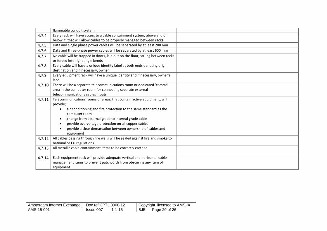
flammable conduit system 4.7.4 Every rack will have access to a cable containment system, above and or
below it, that will allow cables to be properly managed between racks
4.7.5 Data and single phase power cables will be separated by at least 200 mm 4.7.6 Data and three-phase power cables will be separated by at least 600 mm 4.7.7 No cable will be trapped in doors, laid out on the floor, strung between racks
or forced into right angle bends
4.7.8 Every cable will have a unique identity label at both ends denoting origin, destination and if necessary, owner
4.7.9 Every equipment rack will have a unique identity and if necessary, owner’s label
4.7.10 There will be a separate telecommunications room or dedicated ‘comms’ area in the computer room for connecting separate external telecommunications cables inputs.
4.7.11 Telecommunications rooms or areas, that contain active equipment, will provide;
• air conditioning and fire protection to the same standard as the computer room
• change from external grade to internal grade cable • provide overvoltage protection on all copper cables • provide a clear demarcation between ownership of cables and
equipment
4.7.12 All cables passing through fire walls will be sealed against fire and smoke to national or EU regulations
4.7.13 All metallic cable containment items to be correctly earthed
4.7.14 Each equipment rack will provide adequate vertical and horizontal cable management items to prevent patchcords from obscuring any item of equipment
Amsterdam Internet Exchange Doc ref CPTL 0908-12 Copyright licensed to AMS-IX AMS-15-001 Issue 007 1-1-15 BJE Page 20 of 26

4.8 Building Management Systems and monitoring
Minimum requirements Audit results and comments 4.8.1 The computer room will have at least one general temperature sensor and
one general humidity sensor for the room
4.8.2 Telecommunications and plant rooms will have a general temperature and humidity sensor
4.8.3 There will be a water sensor under every raised floor, every CRAC unit and every water cooled rack and also in every plant room
4.8.4 A software-based BMS will monitor -every temperature, humidity and water sensor -the status of the fire alarm panel -the status of the security/access control system -the status of the incoming mains and automatic transfer switch -the status of the generators -the status of each UPS and CRAC unit -the status of any fire/smoke control or HVAC dampers -its own status
4.8.5 This information will be displayed on a dedicated BMS terminal with graphical interface
4.8.6 The essential items of the BMS system will have a dedicated UPS supply with at least one hour of battery time or with other power backup methods.
4.8.7 A management strategy will be in place that will describe the reaction to each alarm, who will respond and response outside of normal working hours
4.8.8 Essential alarms will connect via an external telecommunications circuit to an agreed list of stakeholders
4.8.9 The BMS will store historical trends and generate incident logs and reports 4.8.10 The BMS will be fail safe in that if it should fail it will not affect the operation
of any system that it purely monitors
Amsterdam Internet Exchange Doc ref CPTL 0908-12 Copyright licensed to AMS-IX AMS-15-001 Issue 007 1-1-15 BJE Page 21 of 26

5 Operat ional Requirements
Management techniques must be put in place that give operating procedures and protocols that ensure the continuing efficient and reliable operation of the data centre and timely communication to all stakeholders. 5.1 Good work practices in the building
Minimum requirements Audit results and comments 5.1.1 The data centre will have one central manned pedestrian entrance and one
general loading bay area
5.1.2 All equipment will be unpacked and assembled in a dedicated ‘build’ area and not in a live computer room
5.1.3 There will be a dedicated control room or area. All control and monitoring functions will be connected into and displayed in the control room
5.2 Operational Management Documentation required
Minimum requirements Audit results and comments 5.2.1 A general operations manual is required that brings together all the
operating requirements and settings of the data centre
5.2.2 All major items of equipment, e.g. UPS, HVAC, generator etc shall be included in an asset register which will include a settings and operational procedure to include • Location • Serial number • Data of procurement • Manufacturer contact details • Maintenance/call out contact details • Service history
Amsterdam Internet Exchange Doc ref CPTL 0908-12 Copyright licensed to AMS-IX AMS-15-001 Issue 007 1-1-15 BJE Page 22 of 26

• Dates of calibration if required • Settings and set points to be observed e.g. RH and return temperature on
CRAC units 5.2.3 A checklist is required of all items that need to be left in an ‘automatic’
status and where these controls are located, e.g. fire control panel and gas suppression system, activation of standby generator etc
5.2.4 Site documentation information to include • Building and floor plans • Locations of racks and other major items of equipment • Rack layout • Logical and physical interconnectivity of equipment
5.2.5 A ‘call list’ is to be available which will list all principle staff of the data centre, their function and contact details plus any appropriate suppliers, maintenance companies and emergency services
5.2.6 The data centre will have a safety operations manual that will detail • Safe working at height • Safe use of electricity • Use of laser transmission equipment • Lifting heavy loads • Monitoring of noise in the workplace • Use of barriers around work areas such as missing floor tiles etc
5.2.7 An algorithm chart is required that will detail the cause and effect of all related • Fire detection • Alarm states • Activation of gas suppression • Control of dampers • Powering off of power supply equipment • Powering off of HVAC units • Restart procedures
5.2.8 A method statement is required detailing how visitors will be identified and escorted around the site
5.2.9 A method statement is required detailing how external contractors may enter and work on the site and how their work is monitored, controlled and
Amsterdam Internet Exchange Doc ref CPTL 0908-12 Copyright licensed to AMS-IX AMS-15-001 Issue 007 1-1-15 BJE Page 23 of 26

recorded 5.2.10 An audit trail is required that demonstrates how changes to the design and
fabric of the data centre are made. This could be by a Change Control Document and Work Order method
5.2.11 A written plan must be in place that details how all alarms states and system failures will be handled by the data centre staff
5.3 Maintenance procedures
Minimum requirements Audit results and comments 5.3.1 Any internal staff involved in maintenance must be trained and qualified to
do so. A personal statement must demonstrate how this competence has been achieved e.g., professional/trade qualifications, attendance at manufacturers’ training courses etc
5.3.2 Any external contractor involved in maintenance must also be able to demonstrate competence
5.3.3 All equipment requiring maintenance shall have a maintenance log detailing the equipment, maintenance dates, outcomes, contact details etc. See 4.2.2
5.3.4 Maintenance on critical items must take place at agreed times. These will be during 07h00-12h00 (GMT +1h). Incident Management, i.e., to bring a component back into production after a failure, should be done between 00h00 and 07h00Maintenance will be pre-announced to stakeholders at least one week in advance. There will be no routine maintenance work on critical items outside of these time windows.
Amsterdam Internet Exchange Doc ref CPTL 0908-12 Copyright licensed to AMS-IX AMS-15-001 Issue 007 1-1-15 BJE Page 24 of 26

6 Business Continuity requirements
Recovery plans must be in place that has an established and rehearsed procedure for dealing with any incident that impairs the operation of the data centre and puts in to place a recovery programme. An ICT continuity programme must
• Understand the threats to, and vulnerabilities of, ICT services • Identify the potential impacts of disruption to ICT services • Provide collaboration between data centre staff, internal and external service providers and stakeholders • Demonstrate competence by credible responses through exercising ICT continuity plans and test ICT continuity arrangements
The data centre must be able to
• Protect the ICT environment through resilient design and best practice engineering • Detect incidents at the earliest opportunity • React to an incident in an appropriate manner • Recover the data processing and communications systems in a prioritised manner • Operate in a disaster recovery mode until normal operations are possible • Return to a normal business position
6.1 Incident handling and disaster recovery
Minimum requirements Audit results and comments 6.1.1 The data centre must have a risk assessment analysis that details risks, the
impact of these risk and the strategy to obviate these risks, e.g. • Site: fire, flooding • Operations: power supply failure etc. • Personnel: major epidemic etc.
Amsterdam Internet Exchange Doc ref CPTL 0908-12 Copyright licensed to AMS-IX AMS-15-001 Issue 007 1-1-15 BJE Page 25 of 26

• Communications: main cable damage 6.1.2 All critical systems such as UPS status, fire conditions etc., must be
automatically monitored. These are detailed in section 4.8
6.1.3 Any critical failure or loss of service must be communicated to AMS-IX by telephone within five minutes
6.1.4 Any critical failure or loss of service must be automatically communicated to all relevant personnel, management and other stakeholders within five minutes
6.1.5 The method of communication to external agencies and stakeholders must be independent of the same critical facilities that have failed e.g. essential monitoring and communications equipment must be powered by an independent battery-backed supply
6.1.6 A written plan must be in place that details how all alarms states and system failures will be handled by the data centre staff
6.1.7 All major incidents will be subject to a management review that will detail • What the incident was • Where it happened • When it happened • What was the impact on service provision • How was it dealt with • What changes can be made to prevent a similar incident happening again
6.1.8 A statement is required that will detail the impact of a sudden and complete loss of power on the ICT equipment and how a restart will be managed
6.1.9 A ‘call list’ is to be available which will list all principle staff of the data centre, their function and contact details plus any appropriate suppliers, maintenance companies and emergency services. Contact details must also include ‘out-of-hours’ contact details and define responsibilities of all the parties.
6.1.10 The effects of power cuts must be simulated to prove the operation of UPS and generator start up routines. These simulations must be treated as maintenance episodes and take place and be communicated as 5.3
Amsterdam Internet Exchange Doc ref CPTL 0908-12 Copyright licensed to AMS-IX AMS-15-001 Issue 007 1-1-15 BJE Page 26 of 26