an acoustical finite element model of perforated elements · an acoustical finite element model of...
TRANSCRIPT
An Acoustical Finite Element Model
of Perforated Elements
Paolo Bonfiglio and Francesco Pompoli
Presented at the COMSOL Conference 2009 Milan
Outline
• Introduction• Theoretical background• Acoustical resonators• Perforated elements in mufflers• Concluding remarks

IntroductionResonating systems are widely used in several noise control
applications
In literature it is possible to find analytical formulas based on fluid-dynamics concepts for evaluating losses occurring across the holes of these panels.
An acoustical FE formulation for modeling losses in the openingswill be presented and validated against experimental tests.
Risonatore – top acust Marmitta
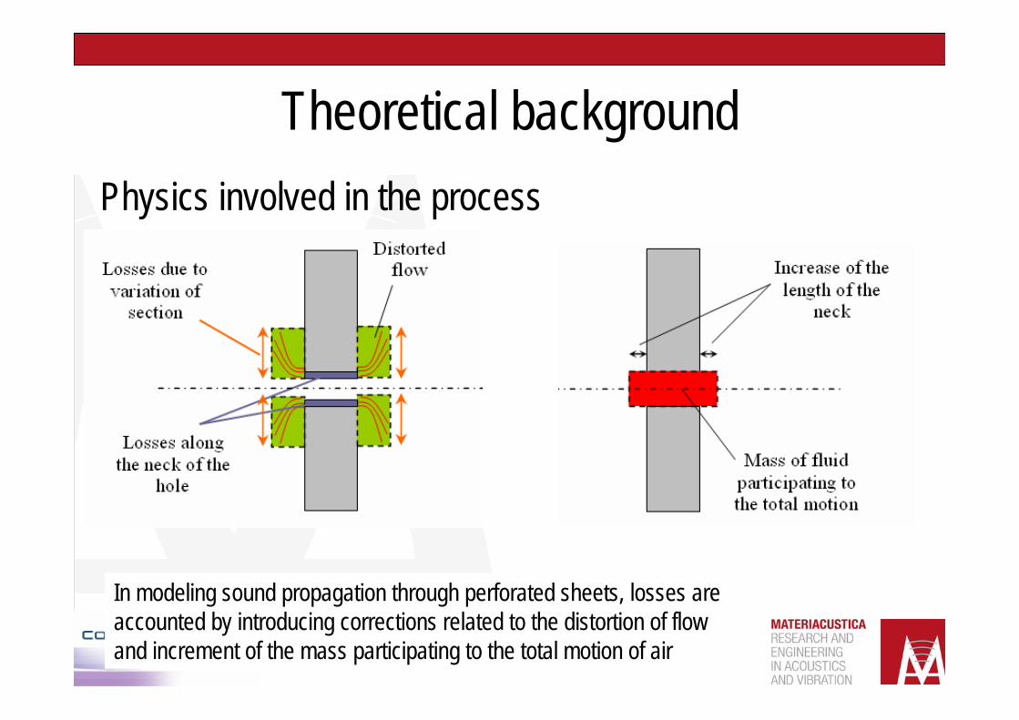
Theoretical backgroundPhysics involved in the process
In modeling sound propagation through perforated sheets, losses are accounted by introducing corrections related to the distortion of flow and increment of the mass participating to the total motion of air
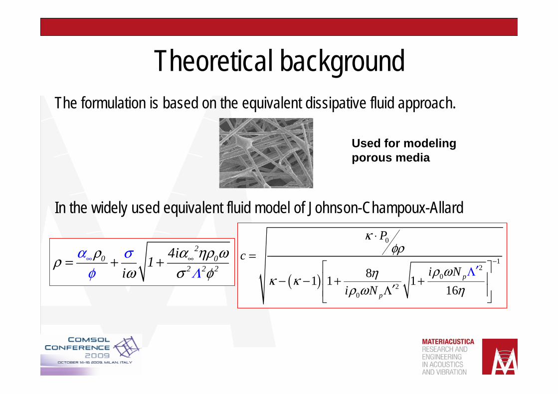
Theoretical backgroundThe formulation is based on the equivalent dissipative fluid approach.
In the widely used equivalent fluid model of Johnson-Champoux-Allard
α σρ α ηρ ωρω σφ φΛ
∞ ∞= + +2
0 02 2 2
4i1i ( )
0
12
02
0
81 1 116
κφρ
ρ ωηκ κρ ω η
−
⋅=
⎡ ⎤⎢ ⎥− − + +
′Λ⎢
′
⎥⎦
Λ
⎣
p
p
Pc
i Ni N
Used for modelingporous media
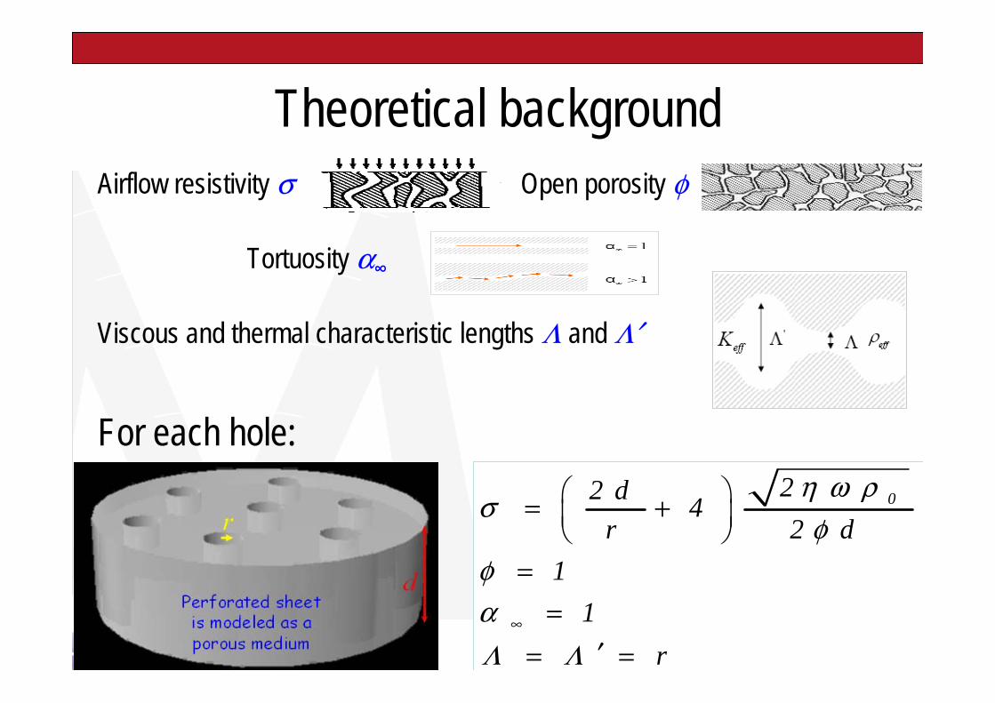
Theoretical backgroundAirflow resistivity σ Open porosity φ
Tortuosity α∞
Viscous and thermal characteristic lengths Λ and Λ′
For each hole:η ω ρ
σφ
φαΛ Λ
∞
⎛ ⎞= +⎜ ⎟⎝ ⎠
==
′= =
022 d 4r 2 d
11
r
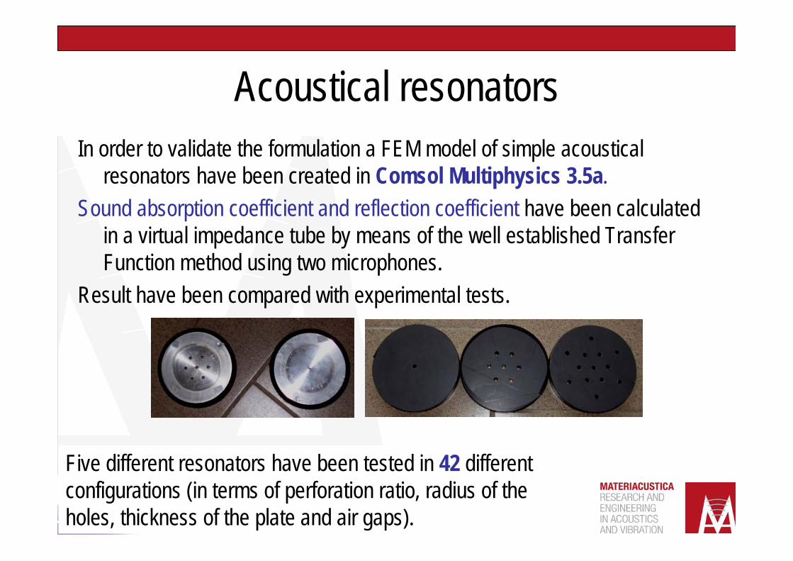
Acoustical resonatorsIn order to validate the formulation a FEM model of simple acoustical
resonators have been created in Comsol Multiphysics 3.5a.Sound absorption coefficient and reflection coefficient have been calculated
in a virtual impedance tube by means of the well established Transfer Function method using two microphones.
Result have been compared with experimental tests.
Five different resonators have been tested in 42 different configurations (in terms of perforation ratio, radius of the holes, thickness of the plate and air gaps).
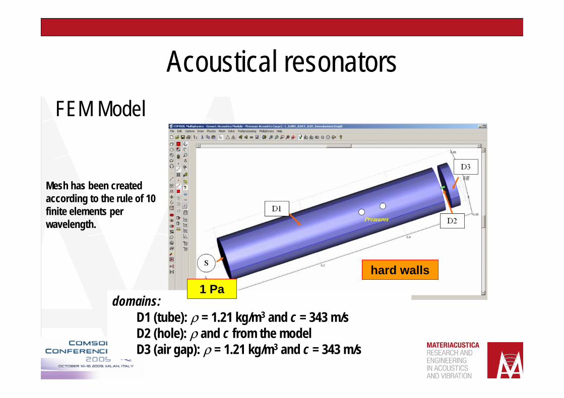
Acoustical resonatorsFEM Model
domains:D1 (tube): ρ = 1.21 kg/m3 and c = 343 m/sD2 (hole): ρ and c from the modelD3 (air gap): ρ = 1.21 kg/m3 and c = 343 m/s
1 Pahard walls
Mesh has been created according to the rule of 10 finite elements per wavelength.
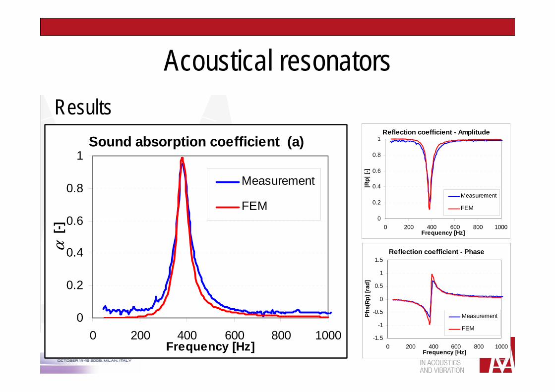
Acoustical resonatorsResults
Sound absorption coefficient (a)
0
0.2
0.4
0.6
0.8
1
0 200 400 600 800 1000Frequency [Hz]
α [-
]
Measurement
FEM
Reflection coefficient - Amplitude
0
0.2
0.4
0.6
0.8
1
0 200 400 600 800 1000Frequency [Hz]
|Rp|
[-]
Measurement
FEM
Reflection coefficient - Phase
-1.5
-1
-0.5
0
0.5
1
1.5
0 200 400 600 800 1000Frequency [Hz]
Phs(
Rp)
[rad
]
Measurement
FEM
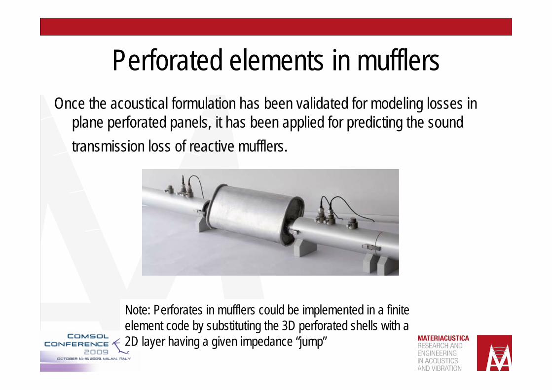
Perforated elements in mufflersOnce the acoustical formulation has been validated for modeling losses in
plane perforated panels, it has been applied for predicting the sound transmission loss of reactive mufflers.
Note: Perforates in mufflers could be implemented in a finite element code by substituting the 3D perforated shells with a 2D layer having a given impedance “jump”
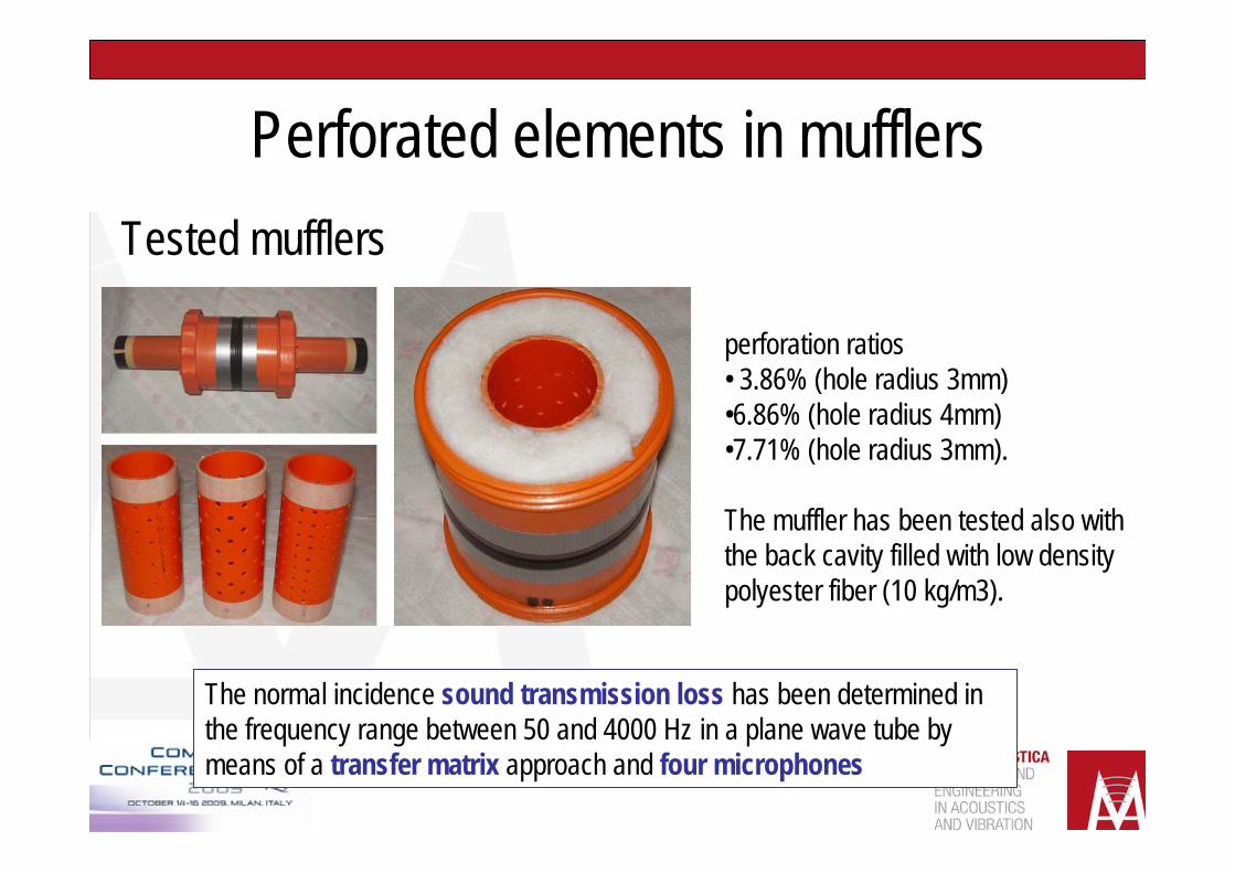
Perforated elements in mufflersTested mufflers
perforation ratios • 3.86% (hole radius 3mm)•6.86% (hole radius 4mm) •7.71% (hole radius 3mm).
The muffler has been tested also with the back cavity filled with low density polyester fiber (10 kg/m3).
The normal incidence sound transmission loss has been determined in the frequency range between 50 and 4000 Hz in a plane wave tube by means of a transfer matrix approach and four microphones
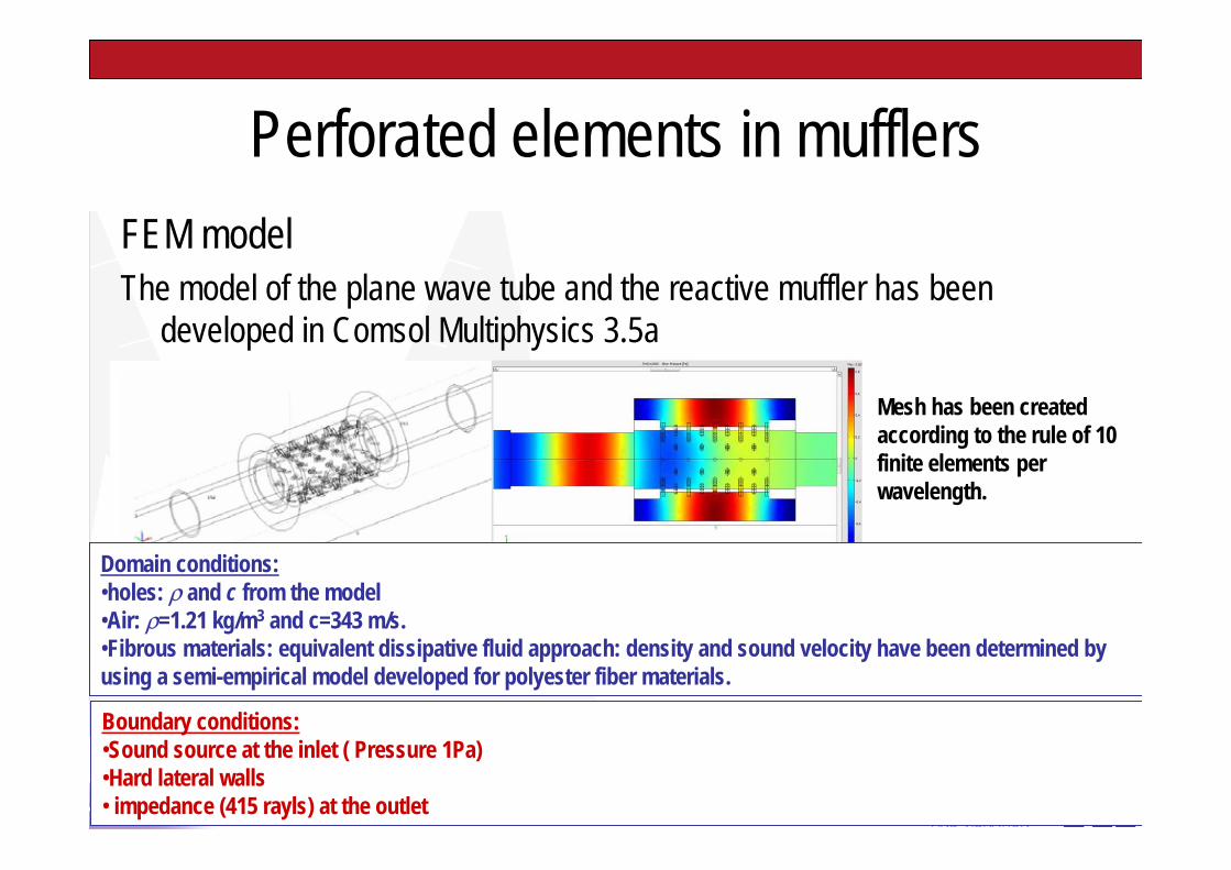
Perforated elements in mufflersFEM modelThe model of the plane wave tube and the reactive muffler has been
developed in Comsol Multiphysics 3.5a
Domain conditions:•holes: ρ and c from the model•Air: ρ=1.21 kg/m3 and c=343 m/s.•Fibrous materials: equivalent dissipative fluid approach: density and sound velocity have been determined by using a semi-empirical model developed for polyester fiber materials.
Mesh has been created according to the rule of 10 finite elements per wavelength.
Boundary conditions:•Sound source at the inlet ( Pressure 1Pa)•Hard lateral walls• impedance (415 rayls) at the outlet
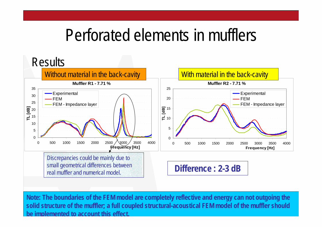
Perforated elements in mufflersResults
Muffler R1 - 7.71 %
0
5
10
15
20
25
30
35
0 500 1000 1500 2000 2500 3000 3500 4000Frequency [Hz]
TL [d
B]
ExperimentalFEMFEM - Impedance layer
Muffler R2 - 7.71 %
0
5
10
15
20
25
0 500 1000 1500 2000 2500 3000 3500 4000Frequency [Hz]
TL [d
B]
ExperimentalFEMFEM - Impedance layer
Without material in the back-cavity With material in the back-cavity
Note: The boundaries of the FEM model are completely reflective and energy can not outgoing the solid structure of the muffler; a full coupled structural-acoustical FEM model of the muffler should be implemented to account this effect.
Difference : 2-3 dBDiscrepancies could be mainly due to small geometrical differences between real muffler and numerical model.
Concluding remarks• An acoustical formulation (based on the conept of equivalent dissipative
fluid) for the FEM modeling in Comsol Multiphysics 3.5a of the losses in perforates.
• Initially the formulation has been applied to plane acoustical resonators and sound absorption coefficient has been calculated with satisfying accuracy at normal incidence.
• Successively the same formulation has been utilized to model perforates within a muffler and to predict its normal incidence sound transmission loss. The FEM model has permitted a reliable prediction of the sound transmission loss also in the case of back cavity filled with fibrous material.
• Future effort will be devoted to include mean flow and temperature effects through the holes of the perforates as well as the absorbing materials.