an empirical study of a language based security …
TRANSCRIPT

AN EMPIRICAL STUDY OF A LANGUAGE BASED SECURITY
TESTING TECHNIQUE
by
MUHAMMAD HOSAM ABOELFOTOH
A thesis submitted to the Department of Computing
In conformity with the requirements for
the degree of Master of Science
Queen’s University
Kingston, Ontario, Canada
September, 2008
Copyright © Muhammad Hosam Aboelfotoh, 2008

Abstract
Application layer protocols have become sophisticated to the level that they have become
languages in their own right. Security testing of network applications is indisputably an essential
task that must be carried out prior to the release of software to the market. Since factors such as
timetomarket constraints limit the scope or depth of the testing performed, it is difficult to carry
out exhaustive testing prior to the release of the software. As a consequence, flaws may be left
undiscovered by the software vendor, which may be discovered by those of malicious intent.
We report the results of an empirical study of testing the Distributed Relational Database
Architecture (DRDA®) protocol as implemented by the IBM® DB2® Database for Linux®,
Unix®, and Windows® product, using a security testing approach, and a framework which
implements that approach, that emerged from the joint work of the Royal Military College of
Canada and Queen's University of Kingston. The previous version of the framework was used in
the past to test the implementations of several network protocols. Compared to DRDA, these
protocols are relatively simple, as they possess a much fewer number of structure types, messages
and rules.
From our study of the DRDA protocol, several omissions in the framework were
uncovered, and were implemented as part of this work. In addition, the framework was
automated, a preliminary automated test planner was created and a primitive language was
created to provide the ability to describe custommade test plans. Testing revealed two faults in
the DB2 server, one of which was unknown to the vendor, prior to the testing that was carried out
as part of this thesis work.
i

Acknowledgements
First of all, I would like to express my sincere gratitude to my professor Dr. Thomas
Dean, for his patience and guidance throughout the course of this work. I would like to thank
Ryan Mayor from the IBM DB2 Release Management Team, for his support throughout the
testing phase. I would also like to thank all those at IBM who followed up with the research.
Many thanks goes to the previous students that worked on this project. My work was a
continuation of their past work and I am grateful to have been part of this project.
I would like to thank IBM for their support in funding this project.
ii

Table of Contents
Abstract.............................................................................................................................................i
Acknowledgements..........................................................................................................................ii
Table of Contents............................................................................................................................iii
List of Figures.................................................................................................................................vi
List of Tables.................................................................................................................................vii
Glossary........................................................................................................................................viii
Chapter 1 Introduction...................................................................................................................1
1.1 Introduction and Motivation.................................................................................................1
1.2 Objective of This Thesis......................................................................................................2
1.3 Thesis Outline......................................................................................................................3
Chapter 2 Background...................................................................................................................4
2.1 Introduction..........................................................................................................................4
2.2 Software Testing and Techniques........................................................................................4
2.2.1 Blackbox Testing.........................................................................................................4
2.2.2 Modelbased Testing.....................................................................................................5
2.2.3 Syntax Testing..............................................................................................................5
2.2.4 Test Case Generation in Syntax Testing........................................................................6
2.2.4.1 Syntax Errors..........................................................................................................6
2.2.4.2 Delimiter Errors.....................................................................................................6
2.2.4.3 Fieldvalue Errors...................................................................................................6
2.2.4.4 Contextdependent and Statedependent Errors......................................................7
2.2.5 Mutation Testing...........................................................................................................7
2.2.6 Languagebased Testing................................................................................................8
2.3 TXL.....................................................................................................................................8
2.4 ASN.1..................................................................................................................................8
2.5 Existing Testing Approaches In Literature.........................................................................10
2.5.1 PROTOS.....................................................................................................................10
2.5.2 Network Protocol Implementation Testing at Cisco....................................................11
2.5.3 Mutation Testing of Protocol Messages Based on Extended TTCN3........................12
2.5.4 Protocol Tester Approach............................................................................................14
iii

2.6 Protocol Tester...................................................................................................................15
2.6.1 Network Listener.........................................................................................................15
2.6.2 Decoder and Encoder..................................................................................................16
2.6.3 Protocol Description....................................................................................................16
2.6.4 Protocol Factbase........................................................................................................16
2.6.5 PDU Factbase..............................................................................................................17
2.6.6 Data Dependencies Script Generator...........................................................................17
2.6.7 Injector........................................................................................................................19
2.6.7.1 Simplifier Function..............................................................................................23
2.6.7.2 Lookup Function..................................................................................................23
2.6.7.3 Rewrite Function..................................................................................................24
2.6.7.4 The injection process............................................................................................25
2.6.8 Test Planner................................................................................................................26
2.6.9 Markup and Execution................................................................................................26
2.7 Previous Vulnerability Testing Results by Protocol Tester................................................28
2.7.1 Testing SNMP.............................................................................................................29
2.7.2 Testing X.509..............................................................................................................29
2.7.3 Testing Open Shortest Path First (OSPF)....................................................................29
2.7.4 Testing SMB protocol.................................................................................................30
2.7.5 Testing AppleTalk Filing Protocol..............................................................................30
2.8 DRDA................................................................................................................................31
Chapter 3 Methodology...............................................................................................................33
3.1 Introduction........................................................................................................................33
3.2 Describing DRDA in the Security and Constraints Language (SCL).................................34
3.3 Capturing the PDU sequence.............................................................................................36
3.4 Packet Flow Analysis, Test Planning and Execution..........................................................37
3.5 Database Backup................................................................................................................38
3.6 Test Sequence Configuration.............................................................................................39
Chapter 4 Framework Extensions................................................................................................41
4.1 Introduction........................................................................................................................41
4.2 Test Planning.....................................................................................................................41
4.2.1 Binding........................................................................................................................42
iv

4.2.2 PreInvalid Range Generation.....................................................................................43
4.2.3 Invalid Range Generation............................................................................................44
4.2.4 PostInvalid Range Generation....................................................................................45
4.2.5 Length Fields Fact Base..............................................................................................45
4.2.6 Field Types Fact Base.................................................................................................46
4.2.7 Custom Mutations.......................................................................................................46
4.2.7.1 Insert....................................................................................................................48
4.2.7.2 Remove................................................................................................................48
4.2.7.3 SetValue...............................................................................................................48
4.2.7.4 Permute................................................................................................................48
4.3 Modifications to the Markup Engine..................................................................................49
4.4 Constraints.........................................................................................................................53
4.5 PDU Decoding...................................................................................................................54
4.6 Injector...............................................................................................................................55
Chapter 5 Test Results.................................................................................................................57
5.1 Introduction........................................................................................................................57
5.2 DDM Messages..................................................................................................................57
5.3 DRDA Flows.....................................................................................................................58
5.4 Continue Query (CNTQRY) Command.............................................................................65
5.5 Indepth analysis of DRDA Test Sequences......................................................................66
5.6 DRDA Test Sequence Results............................................................................................77
Chapter 6 Conclusions and Future Work.....................................................................................80
6.1 Introduction........................................................................................................................80
6.2 Contributions.....................................................................................................................81
6.3 Future Work.......................................................................................................................82
6.4 Conclusions........................................................................................................................83
Trademarks..................................................................................................................................84
References...................................................................................................................................85
Appendix.....................................................................................................................................89
v

List of Figures
Figure 2.1 ASN.1 Description of SPP [5].......................................................................................9
Figure 2.2 General Structure of the security testing framework....................................................15
Figure 2.3 The Data Dependencies Script Generator structure in the framework.........................19
Figure 2.4 Sample Data Dependencies Script...............................................................................22
Figure 2.5 Sample Data Dependencies Script Parse Tree.............................................................22
Figure 2.6 Markup Output............................................................................................................27
Figure 2.7 Markup Implementation Output...................................................................................28
Figure 2.8 A single Data Stream Structure (DSS).........................................................................32
Figure 2.9 Command/Object/Reply structure................................................................................32
Figure 3.1 Methodology Overview...............................................................................................33
Figure 3.2 PDML file partial output..............................................................................................37
Figure 4.1 Test Planner Architecture............................................................................................42
Figure 4.2 binding.txl output sample............................................................................................43
Figure 4.3 Sample preIRG.txl output............................................................................................43
Figure 4.4 Parse tree of preIRG.txl output....................................................................................44
Figure 4.5 postIRG.txl sample output...........................................................................................45
Figure 4.6 Rqsdss length constraint..............................................................................................45
Figure 4.7 Lengthfield.db sample output......................................................................................45
Figure 4.8 Field Types Fact Base..................................................................................................46
Figure 4.9 Sample Search Result..................................................................................................47
Figure 4.10 Custom Mutations Script sample...............................................................................48
Figure 4.11 Default mutation script..............................................................................................49
Figure 4.12 Sample lengthfields.db...............................................................................................50
Figure 4.13 PDU field name of 'rdbnam'.......................................................................................50
Figure 4.14 Search results for matching PDU field names to protocol field name
'Rqsdss_header_DssHeader_lenField'...........................................................................................52
Figure 4.15 Previous constraint syntax.........................................................................................53
Figure 4.16 PDU sequence reconstruction packet list file............................................................55
vi

List of Tables
Table 2.1: Mutation Strategies at the Abstract Syntax Level........................................................28
Table 4.1 PDU grandparent fieldnames corresponding to the protocol field names found from the
length field fact base.....................................................................................................................52
Table 4.2 TCP/IP injector interface functions...............................................................................56
Table 5.1 Test Results Summary..................................................................................................79
vii

Glossary
ABNF Augmented Backus Naur Form, an extension to BNF.
AFP AppleTalk Filing Protocol, a filesharing protocol for Apple MacIntosh Computers.
ASCII American Standard Code for Information Interchange. A character encoding based on
the English alphabet.
ASN.1 Abstract Syntax Notation One, a grammar notation for protocols.
BNF Backus Naur Form, a metasyntax used to express contextfree grammars.
BER Basic Encoding Rule, a method of encoding PDUs on the network.
CIFS Common Internet File System, the new version of the SMB protocol.
Codepoint Object or structure type
DoS Denial of Service, an attack that denies the use of a service to others.
EBCDIC Extended Binary Coded Decimal Interchange Code
EBNF Extended Backus Naur Form.
ER model A way of graphically representing entity sets and the logical relationships
between them.
Factbase A fact representation of an ER data model.
GNU GNU's Not Unix; Free Software
GPL General Public License
Grok A language and interpreter by Ric Holt of Waterloo University that implements a Tarski
Relational algebra engine.
HTTP Hyper Text Transfer Protocol, the protocol used to transfer webpages between the
server and the browser.
IUT Implementation Under Test.
LAN Local Area Network.
viii

LSA Link State Advertisements, a method used by routers to exchange information, in
the OSPF protocol.
LU Logical Unit. Identifies an end user in an SNA network. An end user is either a human being
interacting with the network or an application program that indirectly represents such an end user.
MAC OS An Operating System developed by Apple Computer Inc.
OSPF A router protocol used within larger autonomous system networks.
PDU Protocol Data Unit, the basic unit of data exchange in a protocol.
PKI Public Key Infrastructure, enables users of an insecure network to securely and privately
exchange data through the use of a cryptographic key pair.
SCL A protocol description language used as part of the framework.
SMB Server Message Block protocol, a communication protocol for sharing files.
SNA Systems Network Architecture, IBM's proprietary networking architecture. A complete
protocol stack for interconnecting computers and their resources.
SNMP Simple Network Management Protocol.
SNORT An intrusion detection system. It can also be used as a network traffic listener.
Socket A network communication endpoint
SQL Server Query Language. A language used to retrieve and manage data in databases.
S.U.T. System Under Test. A system which consists of an Implementation Under Test (IUT).
TCP/IP Transmission Control Protocol / Internet Protocol
TXL A programming language used for software analysis and source transformation.
UAM User Authentication Methods.
UNICODE An industry standard set of character encodings.
X.509 Refer to the series of standards defining the basis for a PKI.
ix

Chapter 1 Introduction
1.1 Introduction and Motivation
In today's world, different software vendors race against time, and compete against each
other, to get their products out to the market. This puts developers under timetomarket
constraints. Since the developers have to ensure a product which provides a working set of
features to the customer, conformance testing is carried out on the product to ensure correct
functionality. This leaves little or no time for adequate testing of the product's security.
Network applications use protocols to communicate and exchange data over the network.
A formal language is a set of syntactic and semantic rules which describe their structure and
meaning respectively [33]. Since a protocol is a set of rules that govern the syntax and semantics
of communication, they are formal languages in their own right. Protocols can become complex
in nature, and so it is unlikely that developers implementing these protocols, which are subjected
to development pressures such as timetomarket constraints, produce software which is free from
security vulnerabilities. So therefore, testing is vital in strengthening the security of network
applications.
Before launching network applications onto the market, these applications usually go
through traditional conformance testing. Traditional conformance testing tends to focus on the
correct implementation of the desired functionality, such as producing valid requests from a peer
network application, and receiving valid responses, as well as handling obvious errors. Thus this
process on its own does not guarantee the security of the network application. As a result, serious
flaws in these applications may exist. Someone with malicious intent may find and exploit these
1

vulnerabilities and launch a wide range of attacks, such as denialofservice and stealing private
information. Thus we need more efficient techniques for testing the implementation of protocols
in network applications.
This thesis assesses a security testing approach, previously applied in an academic setting
to implementations of the Open Shortest Path First (OSPF) routing protocol [36], the X.509
protocol [34], the Apple Filing Protocol (AFP) [15], the Simple Network Management (SNMP)
protocol [35], the Server Message Block (SMB) protocol [17]. All these protocols are relatively
simple when compared to the Distributed Relational Database Architecture (DRDA) protocol
[20], as they either have fewer message types, fewer structure types, or fewer rules.
1.2 Objective of This Thesis
This work is aimed at applying a testing approach, and a framework which implements
that approach, to an industrial application protocol. We evaluate a lightweight testing technique
and a framework which implements that technique, previously used in an academic setting to test
implementations of relatively smaller protocols with fewer rules and message types, against the
implementation of the DRDA protocol in IBM DB2. DRDA describes over 200 message types
and rules. The goal of this work is to uncover omissions in the previous version of the framework
and implement the extensions necessary for testing DB2. In addition, a preliminary automated
test planner is implemented as part of the extensions to the framework. The test planner also
allows for customized test plans by means of a custom mutations script.
2

1.3 Thesis Outline
In chapter 2, we review some of the existing testing techniques in literature, as well as a
review of the approach that is evaluated in this thesis. We also review the different components
that existed in the previous version of the framework.
In chapter 3, we present the methodology used to test the implementation of the DRDA
protocol. We also highlight on the components used from the previous framework. In chapter 4,
we present the extensions made to the framework, and how each extension was essential in
testing the security of the DB2 server. In chapter 5, we present the results of our study. Finally,
we conclude and discuss future work.
3

Chapter 2 Background
2.1 Introduction
In this chapter we review some of the techniques in software testing. Then we go over the
technique used in this research and where it fits into software testing. In addition, we look at
different approaches that exist in literature, such as PROTOS [6] and the work that stemmed from
Cisco. We also review background on the tools used in this project such as TXL, and standards
such as ASN.1.
2.2 Software Testing and Techniques
Software testing is a process in which software is checked and verified to make sure it
satisfies its requirements and to detect errors. This section reviews some of the different software
testing techniques in the literature.
2.2.1 Blackbox Testing
Blackbox testing is a method by which a system is tested using valid and invalid data
derived from the system's functional (and sometimes nonfunctional) requirements, without
knowing the test system's internal structure. Hence the tester “sees” the system as a “blackbox”.
The tester would then input valid and invalid data into the system, and observes the system's
output.
An advantage of blackbox testing stems from the fact that the tester does not need to
know the implementation details of the System Under Test (SUT), and so the testing team can, to
some extent, be independent of the development team. However, the testing team may collaborate
4

with developers in order to track down the source of defects that were discovered during testing,
by taking the implementation details into account.
2.2.2 Modelbased Testing
In modelbased testing [1], test data is derived from a model that describes the functional
requirements of the System Under Test (SUT). A model of a system is the depiction of its
behavior. A system's behavior can be described in terms of the input sequences to the system, the
actions and the output of the system [1]. Modelbased testing which solely uses functional
requirements and does not depend on the internal details of the implementation of the system, can
be thought of as a type of blackbox testing.
2.2.3 Syntax Testing
Syntax testing, also called grammarbased testing [1], is a static blackbox, datadriven
testing technique for protocol implementations. To create test cases to be used as input to the
System Under Test (SUT), a formal language specification of the protocol is used to represent the
input space. From the grammar the test cases are systematically generated, thereby providing an
effective method for automatically generating the test data.
The human tester would first study the protocol. Then (s)he will describe the input in a
comprehensive descriptive formal language, such as BNF (BackusNaur Form). Rules can then be
applied to the input description, to mutate the syntax of the input, whether by introducing errors
in sentences or in fields of a sentence in the protocol language, and generate test input sentences.
5

2.2.4 Test Case Generation in Syntax Testing
Once the input has been described so that the specification of the protocol is known, we
can start building the test plan and generate our test cases. Beizer [2] suggests that we start by
creating one error at a time, in order to reveal any mutually independent faults, where a fault can
be triggered by just generating a single error for a single field. Then the system can be tested
using combinations of two or more errors, for two or more fields. Now we review the several
kinds of errors that, according to Beizer, can be produced in syntax testing.
2.2.4.1 Syntax Errors
Syntax errors are violations of the grammar of the target language. These errors are
created by adding/removing one or more elements, as well as altering the order of elements.
Syntax errors can be generated at different levels in the grammar hierarchy. At the toplevel,
sentences can be reordered. At the intermediatelevel, the order of fields within one sentence is
altered. At the fieldlevel, mutations of field values can be introduced to generate syntax errors.
2.2.4.2 Delimiter Errors
Delimiters mark the separation of fields in a sentence. For example, delimiters in the
English language are white space characters, commas, semicolons, etc., or their combination.
Delimiters can be omitted, repeated or replaced by other characters, which are not considered as
delimiters by the language. Unbalanced, paired delimiters can also be introduced (e.g. unbalanced
parentheses).
2.2.4.3 Fieldvalue Errors
A fieldvalue error is introduced by setting the value of a field, in a sentence, to an illegal
value. An illegal value is one which does not fall into the allowable range(s) of values specified
6

by the language. These allowable ranges may be fixed in the language, or may vary, depending
on the state at which the fieldvalue is read, as well as the values of other fields.
2.2.4.4 Contextdependent and Statedependent Errors
Contextdependent errors violate the contexts in the target language description, by
creating invalid combinations of syntactically valid sentences. On the other hand, statedependent
errors are generated by inputting a grammatically correct sentence, during the incorrect state.
Using the above syntax testing principles, one can construct a testing framework, which
automatically designs and generates test cases which deliberately violate the language grammar,
and inject these test cases into the Implementation Under Test (IUT), and assess the security of
the IUT, depending on how it reacts to invalid input.
2.2.5 Mutation Testing
Mutation testing [12] is an approach to test data generation that requires knowledge of
code structure. Mutation testing starts with a code component, its associated test cases, and the
test results. The original code component is modified in a simple way to provide a set of similar
component that are called mutants. Each mutant contains a fault as a result of the modification.
Each of the mutants are run using the original test data. If the mutant generates different output
for one of the test cases, it is said to be killed. Mutants that are not killed indicate potential
weaknesses in the test data. Mutations are simple changes in the original code, for example:
constant replacement, arithmetic operator replacement, statement deletion, and logical operator
replacement.
7

2.2.6 Languagebased Testing
In the approach used in this thesis [8], which stems from modelbased testing, we treat
the protocol as a formal language. We derive the test data from a language model [28]. This
language model is built from the specification of the protocol. Semantics and syntax rules in the
protocol specification are described in the Security and Constraints Language (SCL) [5]. The
language model is extracted from the protocol description written in SCL. The testing targets the
syntax and semantic rules of the protocol language description.
2.3 TXL
TXL, the Turing eXtender Language [3], is a programming language specifically
designed for creating, manipulating and rapidly prototyping languagebased descriptions, tools
and applications, using source transformation techniques. It is also used in software analysis and
reengineering tasks [3][16].
A TXL program consists of a BNF grammar which describes the structures of the input
language, and a set of transformation rules, each of which usually consist of a pattern to match,
and a replacement for that pattern.
2.4 ASN.1
Abstract Syntax Notation One (ASN.1) is a standard, formal language that is used to
describe data structures for encoding, transmitting and decoding data. It provides a set of formal
rules for describing the structure of objects that are independent of machinespecific encoding
techniques, and is a precise and formal notation that avoids ambiguities [4].
8

ASN.1 defines a number of primitive or “atomic” types. Among these primitive types
are: INTEGER, an arbitrary integer, OCTET STRING, an arbitrary string of octets (eightbit
values), BIT STRING, an arbitrary string of bits (ones and zeros), IA5String, an arbitrary string
of IA5 (ASCII) characters, and PrintableString, an arbitrary string of printable characters. For
structured types, ASN.1 defines the following four types: SEQUENCE, an ordered collection of
one or more types, SEQUENCE OF, an ordered collection of zero or more occurrences of a given
type, SET, an unordered collection of one or more types, and SET OF, an unordered collection of
zero or more occurrences of a given type. Elements within a structured type can be optional. They
can also have default values. Figure 2.1 is an ASN.1 description of a Sample Pseudo Protocol
(SPP) [5].
PDU ::= (netinfo | roomloc)
Header ::= SEQUENCE {
length INTEGER
appType INTEGER }
netinfo ::= SEQUENCE {
headerNfo header
numOfSubH INTEGER
subheader SET OF address }
address ::=(IPAddress | MACAddress | ErrCode )
IPAddress ::= SEQUENCE {
subType INTEGER
ipaddress INTEGER }
MACAddress ::= SEQUENCE {
subType INTEGER
macaddress OCTET STRING }
ErrCode ::= SEQUENCE {
subType INTEGER
code INTEGER }
roomloc ::= SEQUENCE {
headerNfo header
subheader SET OF roominfo }
roominfo ::= SEQUENCE {
floor INTEGER
officeNumber INTEGER }
Figure 2.1 ASN.1 Description of SPP [5]
9

ASN.1 is used in an extensive range of applications involving the Internet,
intelligent network, cellular phones, groundtoair communications, electronic commerce,
secure electronic services, interactive television, intelligent transportation systems, Voice
Over IP and others.
2.5 Existing Testing Approaches In Literature
2.5.1 PROTOS
PROTOS [6] is a project at the University of Oulu, Finland, that researches security
testing of protocol implementations. Research in the initial 19992001 project was done through a
partnership between the University of Oulu, Finland, and VTT Electronics. The PROTOS project
examined different approaches to testing implementations of protocols using blackbox testing
methods. The objective is to find faults in the IUT, thereby helping in the process of eliminating
faults, some of which may pose security risks.
PROTOS' approach starts by acquiring a formal specification of the target protocol. This
is done by writing up a contextfree description of the protocol's PDU structures, using ASN.1 or
BNF. Semantic rules and complex syntax are implemented as library objects. In order to
minimally simulate the system which interacts with the interface of the IUT, the user constructs
valid PDUs, and sets the PDUs' fields to valid values, in order to create a set of PDUs which
represent valid protocol behavior. The user then creates descriptions of anomalies, which
implement Beizer's syntax testing principles [2], and introduces them into the specification, with
the valid cases as alternatives, thereby creating a 'master' specification, or can also be described as
10

a 'master' grammar. Test cases are designed by combining valid cases and anomalies by creating
instances of the 'master' grammar tree, with particular selections of valid inputs and/or anomalies
for each instance. For stateless protocols, the test case descriptions are encoded and injected
directly into the IUT. For stateful protocols, the test case BNF descriptions have to be evaluated,
by invoking userwritten scripts which use operations to modify the grammar, to minisimulate
the required behavior.
Despite the fact that PROTOS does achieve some level of test execution automation, its
approach suffers from several limitations. First of all, there is no systematic approach by which
the test cases are designed. This is because the user has to manually create the test cases'
descriptions. This implies that the engineering of the test cases depends on the knowledge of the
test designer. Therefore, a more experienced test designer may discover more faults than a less
experienced test designer. Another issue is that, for stateful protocols, the user has to write scripts
to correctly handle the interaction with the IUT. For systems with a large number of states, this
can be a burden on the user.
2.5.2 Network Protocol Implementation Testing at Cisco
A team at Cisco has reported a systematic approach for detecting software defects in
protocol implementations [7]. The approach that they adopted is similar to that of PROTOS' [6],
but extended to overcome some of PROTOS' limitations. Their testing procedure is organized
into three stages: protocol preparation (preprocessing), simulation (packetdriving) and output
analysis (postprocessing).
11

The protocol preparation stage involves protocol study, where the human tester
familiarizes himself/herself with the working mechanism of the target protocol. Once familiarized
with the target protocol, message classification is carried out to identify the key PDU
components. Then packet flow analysis is carried out in order to prepare us for designing
the topologies with largest protocol state space coverage.
The simulation stage constructs the major process in injecting the test cases into the IUT.
The test case generation module generates templates for message mutations with the help of a
comprehensive descriptive language. A test plan is created, from the information collected from
packet flow analysis, and the templates generated from the test case generation module. A
simulation engine then drives the tests and implements the test plan. The protocol robustness is
evaluated in multiple aspects, including conformance verification, stress analysis and Denialof
Service (DoS) assessment. The final process is defect reporting and code profiling.
2.5.3 Mutation Testing of Protocol Messages Based on Extended TTCN3
A recently published paper by Jing et. al. [18] studies the application of a test
specification language, Testing and Test Control Notation version 3 (TTCN3), which is
generally used in conformance testing, to mutation testing. The authors propose a Non
deterministic Finite State Machine (NFSM) model for mutation testing of protocol messages, as
well as an improvement on the verdict mechanism. As reported in the paper, the technique has
been applied against an implementation of the OSPF protocol. TTCN3 includes the ability to
model the state transitions that the implementation may undergo, as well as changes that must be
made to the test data. Anomalies are described by a 'global template' in TTCN3. Extension were
made to the TTCN3 language to provide simple means to describe mutations.
12

The realization stated in this paper is that the transition from an unknown state to a 'reset'
state can be used to detect anomalies in the IUT's behavior. The paper proposes the following
verification sequence to test for failure, normalverificationsequence2_1:
If the IUT has transitioned to an unknown state, then use a forced state transition, a transition that
is known to lead to the initial state s0, to test for failure (by checking if the IUT does return to the
initial state).
The algorithm for testing (compound anomalous test case single mutations) is as
follows:
1. State Leading Sequence (replay to reach test state).
2. Inject anomaly.
3. IUT might have transitioned to unknown state,
4. Force state transition (e.g. use 'state transition reset' and see if the system resets).
For testing DRDA, this would be similar to sending a DRDA INTERRUPT command (to
cancel the unit of work) to the DB2 server after injecting the anomaly, and then replaying the
command in order to inject some other anomaly, rather than tearing down the TCP/IP connection.
This approach still requires that the entire state model has to be described. The advantage
of the approach used in this thesis work, which is presented in the next section, is that we do not
have to describe the entire state model, but rather the data dependencies between the states in the
protocol.
13

2.5.4 Protocol Tester Approach
Protocol Tester [28] is the security testing framework implemented as part of previous
research at Queen's and the Royal Military College of Canada. The approach used in this thesis is
based on that approach [28]. The Protocol Tester approach is described in the next paragraph.
A valid sequence of PDUs is captured from the interaction that occurs between the source
system (client), and the IUT. These captured PDUs are then transformed, using Beizer's syntax
testing principles, to generate malformed PDUs. The test plans are automatically generated based
on the syntax and semantics of the protocol, without user intervention. The security of a protocol
implementation can be assessed by its ability to deal with abnormal input cases, without being
lead to an undefined or incorrect state, or an unhandled situation [8].
Our testing framework is a framework for conducting syntax and semantics testing. This
static blackbox testing method is capable of testing both stateless and stateful protocols. Test
cases are generated “offline” (without the IUT) using a captured valid PDU sequence. The main
realization here is that we can use a valid PDU sequence, captured from the IUT, to move from
one state to the next, without having to construct valid PDUs from scratch. We then test the IUT
by simulating the interaction that involved the sequence of PDUs we've captured, and injecting
anomalies at the state we want to test. Since we are simulating that same interaction that we've
captured, we should receive the same PDUs from the IUT, for the same PDU sequence that we
sent.
14

In this thesis, we have conducted a study of the DRDA protocol, to see how the previous
version of the security testing framework [8] should be extended, in order to be capable of testing
the security of implementations of the DRDA protocol.
2.6 Protocol Tester
In this section, we take a look at the overall architecture of the previous version of the
framework [8], and then describe each component or module in detail. Figure 2.2 gives an
overview of the structure of the security testing framework.
Figure 2.2 General Structure of the security testing framework
2.6.1 Network Listener
This component is used to record the network traffic flowing between the client and the
server. SNORT [11] is used to achieve this. SNORT is an open source network intrusion
15

detection system which can be downloaded freely from the internet. It is capable of performing
realtime traffic analysis and PDU logging on IP networks. It can be used to detect a variety of
attacks, but it can also be used as a network protocol analyzer.
2.6.2 Decoder and Encoder
The decoder is responsible for decoding the binary PDUs, using the protocol description's
grammar, and transforming them into a textual representation. Source transformation techniques
are then applied, using TXL, to collect facts and data from the PDUs. The textual representations
of the PDUs are also used by the test case generator module, along with the protocol description,
for building the test plan and generating the test cases. The encoder transforms the textual
representation of a PDU, to a binary PDU. Both the decoder and encoder are java programs.
2.6.3 Protocol Description
The protocol description is a specification of the protocol and its implementation is to be
tested. This protocol description is a formal language, which obeys the grammar rules of the
Security and Constraints Language (SCL) [5]. SCL is composed of a subset of the industry
standard ASN.1, augmented with what is called a constraints block. The constraints block
provides information on the semantic rules, or constraints, of the protocol.
2.6.4 Protocol Factbase
The protocol factbase contains the dependency relationship information between the
PDUs, as well as the fields involved in the constraints described in the protocol description. A
factbase is a representation of an ER data model in which the relationships between the entities in
16

the data model are described as a set of facts. The protocol factbase (FB) generator, a suite of
TXL programs, is responsible for creating the protocol factbase from the protocol description.
2.6.5 PDU Factbase
The PDU factbase is generated by the PDU factbase (FB) generator, which is a suite of
TXL programs. The PDU factbase contains information on each field in each PDU that was
captured from the IUT. This information represents facts like the starting and ending offset index
of each field in each PDU. The factbase also holds information such as which field belongs to
which PDU, as well as the equivalent field name of the field, in the protocol factbase.
2.6.6 Data Dependencies Script Generator
The Data Dependencies Script Generator is a suite of TXL and Grok [29] programs that
use the facts from the protocol factbase and the PDU factbase, in order to construct a data
dependencies script which describes all the dependencies that exist between the PDUs, as
described by the protocol description. The script specifies which segments of the PDUs we
receive from the IUT, are needed to reconstruct the client PDUs used by the PDU injector. It is
this script, used by the state dependencies handler in the injector, that enables us to reach the state
in the protocol's Finite State Machine (FSM), that we want to test. Figure 2.3 shows the structure
of the data dependencies script generator in the framework.
In addition to dependencies on data received from the server, external data dependencies
may also exist, such as a username and/or a password. These must be provided by the user during
17

the script generation process. The following is a sample from the output of the Data
Dependencies Script Generator:
password == "mypass";
sendPK.2.47.51 == recPK.1.52.56;
sendPK.2.65.88 == encrpPW(password, recPK.1.73.80)
The first line is an assignment of the password string "mypass" to the identifier
'password'. This password string is provided by the user. In the protocol description, an external
dependency would be described using the keyword 'EXTERNAL'. During the data dependencies
script generation process, the data dependencies script generator finds this keyword and prompts
the user for an input, using the identifier associated with the keyword as the variable name. The
second line states that bytes 52 to 56 (inclusive) from the first response PDU should be copied
onto the PDU segment from byte 47 to 51 (inclusive) in the second request PDU, prior to sending
the second request PDU. The third line specifies that the encrpPW function will be invoked with
the value of the password variable as the first parameter, and the segment from byte 37 to 80
(inclusive) from the first response PDU, as the second parameter, and the result of that function
call will be copied onto the PDU segment from byte 65 to 88 (inclusive) in the second request
PDU, prior to sending the second request PDU.
18

Figure 2.3 The Data Dependencies Script Generator structure in the framework
2.6.7 Injector
The injector is a C++ module used to inject PDUs into the IUT. Upon initiating client
emulation, the injector feeds the script which contains the state dependencies, also called the data
dependencies script, to a submodule called the state dependencies handler, to in order to drive
the PDU injection sequence. Based on this script, the state dependencies handler copies whatever
data is necessary from the PDUs received from the IUT, processing the data using builtin
operations, and userdefined modules to handle requirements such as encryption.
The injector connects to the server through the use of a TCP network socket. A network
socket is a communication endpoint, used to communicate with another socket over the network.
19
ProtocolFactBase
PDUFactBase
Grok program
Data Dependencies
File
ProtocolDescription
(SCL)
Decoder
BinaryPDUs
TextPDUs
Network Traffic Listener
ClientSystem S.U.T.
Test CaseGenerator
Injector
Data DependenciesGenerator

The network and host address from the internet communication layer, along with the TCP port for
the process, form a socket. A pair of sockets uniquely identifies each connection [24].
The server uses a socket to listen for connection requests on a particular port. This is
achieved by binding to that port, then starting the listening loop. In order for the client program to
connect to the server, the client binds to a port on its end of the connection, then sends a
connection request from that port, to the port which the server is listening on.
In order to construct a socket, the following three main parameters have to be specified:
the domain parameter, which specifies a communications domain (also known as an address
family) within which the communication will take place. This is to inform the system how the
address should be interpreted; the type parameter, which specifies the semantics of
communication; and the protocol parameter specifies a particular protocol to be used with the
socket. These parameters are described in more detail in the Practical Guide [25].
The injector constructs a socket using AF_INET (Address Family InterNET protocols) as
the domain parameter, SOCK_STREAM (TCP byte stream; a sequenced, reliable, twoway
connection based byte stream) as the type parameter and the protocol parameter is set to 0 for
TCP/IP.
The next step is to build a host entity structure which will hold the host and network
address of the server, the client wants to connect to, as well as the port number the server is
listening for requests on, in order to build the connection. Many network applications use
20

different application level protocols and provide services by listening on ports, some of which are
known standard port numbers. For example, NETBIOS (NET Basic Input/Output System) [30], a
service which allows applications on different computers to communicate over a local area
network, uses the SMB protocol [17] and listens on port 139. Another example is the AppleTalk
service [31] over TCP, which listens on port 548. The framework user specifies the network and
host address of the server, as well as the port number.
Once the injector successfully connects to the server, it can open a socket descriptor, a
unique identifier, of which it will use to send (write) the client requests and receive (read) the
server's responses. By sending the PDUs sent from the actual client to the IUT, from a previously
captured interaction, the injector, with minor modifications to the PDUs, can emulate the actual
client.
After the connection with the server is established, the injector starts to send the actual
client's PDUs, some of which may need modification based on the data dependencies file, as well
as the server's responses. After each response is received, the injector evaluates the data
dependencies expressions to make sure any data required from the PDU received is processed,
and the client's PDU is prepared before it is sent.
This logic is built on the four main functions of the injector: the treebuilding function,
which is used to parse the data dependencies file into a tree; the lookup function, which searches
the dependencies tree for any previously unknown field values which can be known by using the
data from the most recent server response; the simplifier function, which reevaluates expressions
21

in order to simplify them; and the rewrite function, which rewrites the actual client's original
PDU according to the dependency tree.
As mentioned before, the first step the injector performs is parsing the file that describes
the data dependencies between the request PDUs and response PDUs, as well as any external
dependencies that exist. In order to transform the file into a tree, all the sentences become
subtrees and the elements within these sentences become leaves. For example, the treebuilding
function takes as input the data dependencies file in figure 2.4, and outputs a tree that can be
represented by figure 2.5.
Figure 2.4 Sample Data Dependencies Script
Figure 2.5 Sample Data Dependencies Script Parse Tree
22
;
=
,
=
password
.encrpPW
(
password
recPK
1
73 80
.
.
.
mypasswd
sendPK .
.
65 88
2
password == mypasswd;sendPK.2.65.88 == encrpPW(password, recPK.1.73.80)

The tree in figure 2.5 is a binary tree and its root is the delimiter (semicolon) of sentences
that make up the script. Some data variables, such as the 'password' variable in this tree, may
change during the replay and fault injection process, and some subtrees may be substituted by
data that was received from the server. For instance, the righthandside of the second
dependency statement is a function call to encrpPW with a segment from the first server response
PDU as a parameter, in addition to the password string that was input by the user during the script
generation process.
2.6.7.1 Simplifier Function
The simplifier function is used to simplify the tree. Once one or more references to data
segments from a response PDU have been substituted for the referenced data from that PDU, the
binary tree which represents the data dependencies, presented in figure 2.5, can be reevaluated
and reduced. In addition, external data such as a username and password are known from the
point the script is generated, since the user is prompted for external data during the script
generation process. Therefore, the simplifier function can be applied to the initial tree to
substitute the password identifier, which exists as a parameter for the encrpPW function, for its
value 'mypasswd', thus changing the second sentence to "sendPK.2.65.88 ==
encrpPW("mypasswd", recPK.1.73.80).
2.6.7.2 Lookup Function
The Lookup function searches for references to segments in the most recently received
PDU, and if any exist, copies the referenced data segments from the PDU to the tree. For
23

example, the value of recPK.1.73.80 becomes available after the first server response is received.
The lookup function would search the tree for references to the first PDU received (recPK.1). For
every subtree with recPK.1 found, the function will substitute the subtree representing the
recPK.1 and the segment starting and ending indices, for the data segment from the received
PDU, that corresponds to these indices. For example, when the first response PDU is received,
the lookup function will search the tree, and find the reference subtree recPK.1.73.80. Then it will
copy bytes 73 to 80 (inclusive) from the received PDU, and replace the subtree with the data
bytes.
The simplifier function is called after each call to the Lookup function. Now that all
parameters to the encrpPW function call are available, the simplifier function will reduce the tree
even further by calling the function encrypPW with its corresponding parameters, and replacing
the subtree representing the encrpPW function call, with the function return value.
2.6.7.3 Rewrite Function
The Rewrite function is used to generate the next PDU to be sent. It walks the tree and
finds a reference to the next PDU to be sent. If a reference is found, the PDU will be modified
according to the data stored in the tree which corresponds to this PDU. Continuing from the
above example, after the second call to the simplifier function, the right hand side of the
assignment statement in the tree becomes data. The Rewrite function searches the tree and finds a
reference to the segment from byte 65 to byte 88 in sendPK2, which should be changed, and so it
copies the data onto the segment. After returning from the Rewrite function call, the injector will
send the modified PDU to the IUT by writing the PDU to the socket.
24

2.6.7.4 The injection process
In order to successfully reach the state at which we want to test the server, we have to
ensure that the injection process emulates the interaction that runs between the actual client and
the server, as much as possible. Before the injector is run, three files should be ready: the file
which describes the data dependencies between the PDUs, as well as any external data
dependencies, which will be used to drive the injector; the directory that contains the sequence of
PDUs captured while being sent from the actual client, in alphanumeric order; and the directory
which contains the mutated PDUs for the test state. The injection process is as follows:
1. The injector calls the treebuilding function to parse the data dependencies script into a
tree.
2. The injector calls the Simplifier function to reevaluate and attempt to simplify the tree.
3. The injector connects to the server.
4. The injector sends out the first PDU to initiate the replay process.
5. The injector receives the first response from the server.
6. The injector checks if the next state is the state we want to test. If yes, then the injector
will send out a mutated PDU from the set of mutated PDUs created by the test case
generator, terminate the connection, and go back to step 4.
7. The injector calls the Lookup function to check if there is any data required from the
PDU just received. If so, then the subtree which represents the reference to a segment
from that PDU, is replaced by the segment of data from the PDU it referenced.
8. The injector calls the Simplifier function again to see if a further reduction of the tree is
possible after calling the Lookup function.
25

9. The injector calls the Rewrite function to see if the PDU about to be sent out requires
modification. If modifications are required, then the PDU will be modified according to
the information in the tree.
10. The injector sends out either the next original PDU, or the PDU modified by the Rewrite
function, depending on whether or not modification was required, and waits for the server
response, and then goes back to step 4 to prepare the next PDU to send.
2.6.8 Test Planner
The test planner generates mutations of the valid PDUs which were captured from the
IUT. The mutations are generated based on Beizer's syntax testing principles [2], in addition to
violating the semantics of the protocol description language. The facts from the protocol
factbase, as well as facts from the PDU factbase, are used to determine the test cases that should
be generated for each field for each PDU, as well as what type of test cases should be generated
for each constraint.
2.6.9 Markup and Execution
The markup and execution engine implements the test plan produced by the test planner.
It does this by adding markups, or tags, to the fields of the textual representations of the PDUs
which are going to be mutated, according to the test plan. The tags specify the type of mutation to
be generated, as well as any value needed in the process of generating the mutation. These
markedup textual representations of the PDUs then go through a markup execution phase, where
the mutations are implemented, to construct the textual representation of the mutated PDUs.
26

Figure 2.6 shows an example of a textual representation of a decoded PDU, with a
markup tag on one of the fields of the PDU. In the example, the Rqsdss_lenField, which is the
ReQueSt Data Stream Structure's length field, is markedup with “setASNValue (“0 0”)”. This is
an implementation of the fieldvaluechange mutation strategy. In this case we are setting the
length field value to zero (“0 0”).
Figure 2.7 shows the implementation of the mutation strategy in Figure 2.6. In figure 2.6,
which shows the values of the fields of the PDU when the PDU was captured, we see that the
markedup length field held the byte values 0 and 198. These values were changed according to
the markup and were set to the byte values 0 and 0, as shown in figure 2.7.
Figure 2.6 Markup Output
27
! TestCase > 1 > setASNValue "lenField" > sendPK1_PDU : 0 0 : sendPK1 SEQUENCE { sendPK1_PDU_seqOfDss : 0 0 : seqOfDss_PDU_MAINMODULE SEQUENCE { sendPK1_PDU_seqOfDss_seqOfDss_PDU_1_seqOfDss : 0 0 : Rqsdss_MAINMODULE SEQUENCE { sendPK1_PDU_seqOfDss_seqOfDss_PDU_1_seqOfDss_Rqsdss_header : 0 0 : DssHeader_MAINMODULE SEQUENCE { sendPK1_.._Rqsdss_header_DssHeader_lenField : 0 2 :big_endian : INT ErrASN setASNValue ("0 0") 0 198...

! TestCase > 1 > Zero "lenField" > sendPK1_PDU : 0 0 : sendPK1 SEQUENCE {
sendPK1_PDU_seqOfDss : 0 0 : seqOfDss_PDU_MAINMODULE SEQUENCE { sendPK1_PDU_seqOfDss_seqOfDss_PDU_1_seqOfDss : 0 0 : Rqsdss_MAINMODULE SEQUENCE { sendPK1_PDU_seqOfDss_seqOfDss_PDU_1_seqOfDss_Rqsdss_header : 0 0 : DssHeader_MAINMODULE SEQUENCE { sendPK1_.._Rqsdss_header_DssHeader_lenField : 0 2 :big_endian : INT 0 0...
Figure 2.7 Markup Implementation Output
Table 2.1: Mutation Strategies at the Abstract Syntax Level
Mutation Strategy ASN.1 Type Applicability
Removing a field All types
Replacing a field with a specific data structure All types
Changing the value of a field All types
Padding a field with N repetitions of a decimal octet INTEGER, BIT STRING,
OCTET STRING
Padding a field with N repetitions of a character or a digit PrintableString, UTCTIME
Changing element order by swapping the positions of
elements, one at a time
SET, SEQUENCE
2.7 Previous Vulnerability Testing Results by Protocol Tester
The Protocol Tester has been previously used to test for vulnerabilities in several
protocols. In this section we briefly go over the test results for each of these protocols.
28

2.7.1 Testing SNMP
Earlier versions of the Simple Network Management Protocol (SNMP) [35] were tested
with the Protocol Tester framework, and the results obtained were compared with the research
results in PROTOS test suites [6]. In order to compare the results, SNMP was retested with the
PROTOS suites. The Protocol Tester framework produced 2,551 test cases for the SNMP client
applications and yielded results similar to those of PROTOS'. The Protocol Tester did discover
wellknown vulnerabilities [13] in the earlier versions of SNMP. The IUT failed, triggering a
Windows General Protection Failure, on several test cases in the FV10 category; an overflow in
the number of arcs in the OBJECT ID (a field value error) [46].
2.7.2 Testing X.509
Even though the security testing framework did not detect any vulnerabilities in the
X.509 certificate manager application, testing the Public Key Infrastructure (PKI) products
yielded some interesting results. The framework produced 29,136 test cases for X.509
certificates. Potential vulnerabilities in the earlier version were discovered. The system failed,
triggering a Windows General Protection Failure on several test cases, which fall into the the
fieldvalue error and encoding error categories.
2.7.3 Testing Open Shortest Path First (OSPF)
The results obtained from testing the implementation of OSPF in three different IUTs
further confirmed the effectiveness of the approach used in the testing framework. The IUTs
tested were Zebra, Windows 2000 Advanced Server OSPF, and Cisco IOS/OSPF. Fifteen test
suites, each containing between 3,000 to 4,000 mutated PDUs, were produced for each IUT by
29

mutating all five OSPF PDU types. The test cases crashed the systems, which ran the Zebra 0.93
and Windows 2000 Advanced Server, in several situations. Further investigation revealed that
some software bugs in the OSPF checksum function and LSA checksum function can lead to a
denial of service in both IUTs [14].
2.7.4 Testing SMB protocol
The Server Message Block (SMB) protocol [17], which is known as the Common
Internet File System (CIFS) in Microsoft's implementation, is a statebased, commandbased
protocol. There are currently more than 100 commands available, and each of these commands
have their own specific syntax. In a previous study, only three of the most commonly used
commands in SMB, were tested to validate the effectiveness of the framework's testing approach.
The commands are SMB_COM_CREATE, SMB_COM_READ, and SMB_COM_WRITE.
2.7.5 Testing AppleTalk Filing Protocol
The AppleTalk Filing Protocol (AFP) is the filesharing protocol of the AppleTalk
architecture. The AppleTalk architecture, designed for “plug and play”, is found in Mac OS
computers. AFP provides a native mode interface for Apple file system resources [15].
No vulnerabilities were found, however, the framework was capable of emulating the
AFP client, thereby confirming that the framework is capable of testing statebased protocols,
which was the main focus of the previous work done on the testing framework.
30

2.8 DRDA
A study of the DRDA protocol was conducted as part of this thesis. A database protocol
suite used in industry, DRDA describes over 200 rules, element types and messages, making it
relatively much more complex than any of the protocols presented in section 2.7. DRDA stands
for Distributed Relational Database Architecture. It is a set of protocols, developed by IBM, that
permits multiple database systems, as well as application programs, to work together. DRDA
coordinates communication between systems by defining what must be exchanged and how it
must be exchanged. DRDA can be thought of as a “universal, distributed data protocol”. DRDA
describes the contents of all the data objects that flow on either commands or replies, between the
application requester and the application server.
DRDA is built on the Distributed Data Management (DDM) architecture. The DDM
architecture describes the architected commands, parameters, objects, and messages of the DDM
data stream. This data stream accomplishes the data interchange between various pieces of the
DDM model [9].
Influenced by the concepts of objectoriented technology, DDM architecture is
designed to be objectoriented. The DDM architecture enables programs to access and
manage data stored on remote systems in a client/server relationship [10]. In our study,
DB2 server from IBM was used as the IUT, and TCP/IP was used as the transport layer.
In DRDA, there are three types of messages, or data stream structures (DSSs): ReQueSt
DSS (RQSDSS), OBJect DSS (OBJDSS), and RePlY DSS (RPYDSS). When operating at the
31

DDM level, all information is carried in one of these three types of DSSs. A PDU can consist of a
single DSS, or a sequence of DSSs. More than one message can be pipelined into a single PDU,
and more that one DSS might be used by a single command/reply. The format of a single DSS is
shown in figure 2.8.
Length
(2 bytes)
D0 h
(1 byte)
Format
(1 byte)
Correlation
Identifier
(2 bytes)
... data ...
Figure 2.8 A single Data Stream Structure (DSS)
The data carried inside these structures can be one or more commands, objects or replies to
commands. The format of a single command/object/reply is shown in figure 2.9.
Length
(2 bytes)
Codepoint
(2 bytes)
... data ...
Figure 2.9 Command/Object/Reply structure
The length fields in the structures shown in Figure 2.8 and Figure 2.9 specify the total
length of the structure, including the 2byte length field. In a DSS, the length field is followed by
a 1byte constant (D0 h). The constant is then followed by a 1byte integer field, the format field,
which specifies whether the message is a command or an object or a reply. Following the format
field, is the correlation identifier 2byte integer field, which is used to identify structures which
belong to a certain command/reply. The codepoint field in Figure 2.9 is used to specify the type
of command/object/reply message. There are hundreds of message types in DDM.
32

Chapter 3 Methodology
3.1 Introduction
In this chapter we describe the method by which we test the implementation of the
DRDA protocol. The Implementation Under Test (IUT) was DB2 Open Beta Viper [32] from
IBM. Initial tests were done on Version 9.1 (with no service patches) of the IUT, then testing was
moved to Version 9.5 (with no service patches). The IUT was installed on a dualcore machine
with 1 GB of RAM, with the server set up to listen on TCP/IP socket port 50000. The DB2 client,
also on the same machine, using another instance, connects to the server via the loopback
interface. The server's authentication method was kept on the default settings. Most of the test
sequences were obtained from the samples included in the evaluation version of DB2 version 9.5.
Others were generated using custom queries to target specific DRDA messages. The initial state
of the database for each sequence was backed up, and the injector ran a shell script after each
individual sequence of PDU was retransmitted, restoring the database to its original state.
Figure 3.1 Methodology Overview
33
DB2 Server DB2 Client
Network Listener
Packet capture
Packet flow analysisTest planning
Test implementation
ReplayModule
Test run

3.2 Describing DRDA in the Security and Constraints Language (SCL)
In this section, the process of describing the Distributed Relational Database Architecture
(DRDA) protocol specification in SCL [5] is described. In addition, this section highlights several
issues faced when describing the DRDA protocol specification in SCL, as well as how these
issues impact the testing carried out as part of this thesis.
The process of adding codepoints (element types) to the protocol description (see section
2.6.3) is simple. A DRDA PDU is a series of DSS, each DSS carrying either a command, and
object or a reply message. An attempt to decode the PDU sequence is made, if the decoding
process fails, the error logs from the decoding process are checked to find which PDU could not
be decoded. From the protocol study, and our knowledge of what a DSS looks like (see DSS
structure in Chapter 2), we can manually find any unknown codepoint values with ease. These
values are looked up in the DDM reference [20], and the corresponding codepoint structure is
described, along with any codepoint structures it uses as elements. Throughout the course of this
thesis work, 200 codepoints have been described in SCL. Previous implementations tested used
relatively smaller number of codepoints. For example, the Open Shortest Path First (OSPF)
routing protocol only uses five different codepoints. The next few paragraphs summarize some
issues not handled by the framework.
One issue faced, unknown prior to this thesis work, is describing constraints which apply
to elements which may, on some occasions, be ignored by the server. These are referred to as
IGNORABLE elements in the DRDA documentation [20]. For example, if two elements A and B
are OPTIONAL and IGNORABLE elements, then there may exist a case where if element A is
34

ignored by the server, then element B is ignored, otherwise element B may not be ignored. This
case can be found in the Open Query (OPNQRY) Command DDM Structure described in the
DDM reference [20], and applies to the Type of SQL Descriptor (TYPSQLDA) field. This can
only be tested for by removing the field and observing how the server reacts to such mutation.
Note that removing an IGNORABLE element may not result in any error on the server, rendering
the test case useless. This is because the software tester might not know if the element is ignored
by the server.
Another issue, previously known, is that it is not possible to describe constraints on
fields, which depend on the context the field appears in. For example, a field in a client PDU
must have a particular value if a preceding PDU and a proceeding PDU hold particular message
types. Such a case is found in the Atomic Chaining (AC) rules described in the DRDA
documentation volume 1 [20].
Another issue also known prior to this thesis work is that it is not possible to express
constraints which describe data dependencies between client PDUs. This type of data dependency
would only be required by the mutation engine. For example, a field value in a client PDU must
match another field value in a preceding client PDU. A similar case would be Program Binding
(PB) rule 1 specified in the DRDA documentation volume 1 [20].
Since the mutation operations described in section 2.2.4 and Table 2.1 enable the
framework to achieve some test coverage of the logic involved in these constraints, testing can be
carried out with a guarantee that some program coverage will be achieved. By addressing the
35

aforementioned issues one can be assured that the framework can more reliably cover the logic
paths that implement the types of constraints highlighted in the aforementioned issues.
The protocol description, which is an SCL file, is compiled using the 'compile' command,
and the protocol factbase is generated using the 'genprotocolfb' command. The protocol factbase
is generated using the protocol fact base generator described in chapter 2.
3.3 Capturing the PDU sequence
Wireshark [19] is a network protocol analyzer that is under the GNU GPL version 2, and
is free to download. The console version of Wireshark, tshark [19], that comes bundled with the
GUI version, was used. Since Wireshark has the ability to decode DRDA packets to some extent,
we have to disable decoding of DRDA packets by Wireshark, in order to use our framework's
decoder, which uses a better defined protocol description, with more codepoints. This is done by
adding 'drda' to the disabled protocols file 'disabled_protos', in the user's Wireshark directory.
In order to capture the traffic flowing between the DB2 server and the DB2 client, the
user invokes the 'capture' command of the framework. Capturing traffic from the network
requires superuser privileges. After the user becomes superuser, the script associated with the
'capture' command invokes tshark, a network protocol analyzer, with parameters that specify the
traffic that is flowing between the DB2 client and server, as well as the name of the file that will
be used to store the captured binary packets. The user then runs the test sequence interaction
between the DB2 client and the DB2 server. Once the interaction is over, the user terminates
tshark's capture.
36
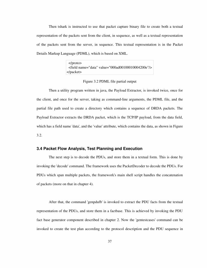
Then tshark is instructed to use that packet capture binary file to create both a textual
representation of the packets sent from the client, in sequence, as well as a textual representation
of the packets sent from the server, in sequence. This textual representation is in the Packet
Details Markup Language (PDML), which is based on XML.
Figure 3.2 PDML file partial output
Then a utility program written in java, the Payload Extractor, is invoked twice, once for
the client, and once for the server, taking as commandline arguments, the PDML file, and the
partial file path used to create a directory which contains a sequence of DRDA packets. The
Payload Extractor extracts the DRDA packet, which is the TCP/IP payload, from the data field,
which has a field name 'data', and the 'value' attribute, which contains the data, as shown in Figure
3.2.
3.4 Packet Flow Analysis, Test Planning and Execution
The next step is to decode the PDUs, and store them in a textual form. This is done by
invoking the 'decode' command. The framework uses the PacketDecoder to decode the PDUs. For
PDUs which span multiple packets, the framework's main shell script handles the concatenation
of packets (more on that in chapter 4).
After that, the command 'genpdufb' is invoked to extract the PDU facts from the textual
representation of the PDUs, and store them in a factbase. This is achieved by invoking the PDU
fact base generator component described in chapter 2. Now the 'gentestcases' command can be
invoked to create the test plan according to the protocol description and the PDU sequence in
37
</proto> <field name="data" value="000ad00100010004200e"/> </packet>

hand. This command uses the test planner and mutation engine to create the test plan for the test
sequence, and implement that plan, in order to generate a set of test cases ready for fault injection.
A 'replay' command can be run to verify that the PDU sequence replay can reach every state in
the sequence without problems. Finally, the 'run' command can be invoked to start the testing
process. For proper set up of the data base prior to running a single test run, the following steps
are taken:
● Capture snapshot of current state of database
● Run single test
● Restore previously captured state of database
3.5 Database Backup
Capturing a snapshot of the database is done by copying the 'sqllib' directory and the
instance directory, which by default has the same name as the user name, that the instance is
using. Both of these directories are, by default, in the instance user's home directory. For
example, the default path under which an instance of DB2 is installed is '/home/db2instX'. Then
the 'sqllib' directory and the instance directory would be '/home/db2instX/sqllib' and
'/home/db2instX/db2instX' respectively. These two directories are backed up by copying the
directories using the UNIX copy command 'cp', to directories with the paths
'/home/db2instX/sqllib_original' and '/home/db2instX/db2instX_original', respectively. The
directories are restored by copying the 'sqllib/db2dump' directory into the original 'sqllib'
directory, then removing the 'sqllib' and 'db2instX' directory, then copying both 'sqllib_original'
and 'db2instX_original' to 'sqllib' and 'db2instX' respectively. Two instances of DB2 were set up.
One was used as the DB2 server (IUT), and the other instance as the actual client (DB2 client).
38

The DB2 server was set up under the instance name of 'db2inst1'. The mechanism used to
authenticate the client was kept to its default settings. During the installation phase, DB2 was set
to listen for TCP/IP connection requests over the default port number 50000. After installation
was complete, the 'sample' database was created, using one of DB2's tools which creates a
database populated with sample data.
The DB2 client was set up under the instance name of 'db2inst2'. The mechanism used
for authentication was kept to its default settings. After the installation phase, the server instance
was cataloged as a TCP/IP node in the DB2 client instance. This was done by creating a new
node with the host name and the port number and the connection mechanism (TCP/IP). The
sample database was also cataloged as a database at the server node. This is so that the client uses
a TCP/IP socket in order to connect to the DB2 server, which would enable us to use a network
listener to capture the packets flowing between the DB2 client and the DB2 server.
3.6 Test Sequence Configuration
Each test sequence created has a configuration file associated with it. In this
configuration file, parameters such as the target host and port number can be specified for use by
the injector. In addition, there is also a 'post_replay_command' parameter which can be set in the
script, which provides the injector with the command to run after running a single replay and
injecting a test case.
39

The 'checkreply' parameter can be set to 'Y' (yes) if we want the replay module to
compare the server's response with the previously captured response, or 'N' if otherwise. The
replay module would print a message after receiving each response, if there is a difference
between the response received, and the response stored, indicating whether there is a difference in
length between the two PDUs, or a difference in the data between the two PDUs, without a
difference in PDU length. From running tests without correctly restoring the data base, we
observed that errors in the replay show up as a sequence of reply PDUs with lengths which are
different to the lengths of the PDUs captured from the interaction with the DB2 client. Therefore,
this diagnostic information can be used to verify if the replay module is capable of reaching the
state we want to test.
We have observed that changes between the server's response during test runs, and the
response PDUs captured from interaction between the IUT and the DB2 client, only occur in the
authentication stage (more on that in chapter 5).
When running the tests, the replay module receives the configuration file name as a
commandline parameter. The replay module passes this file name to the injector, and the injector
fetches the target server host name and port number from the configuration file.
40

Chapter 4 Framework Extensions
4.1 Introduction
In this chapter, we go over several omissions in the previous version of the security
testing framework (see section 2.6), that were uncovered during our study of the DRDA protocol,
and what has been done to address these omissions. We also go over several additions made to
the framework to enhance the usability and overall effectiveness of the framework. In the
upcoming sections, a preliminary automated test planner, which was created as part of this thesis
work, is presented. In addition, the required modifications that were made to the previous
versions of the markup engine, Security and Constraints Language (SCL) [5] grammar definition,
PDU decoder and injector (see section 2.6) are also covered.
4.2 Test Planning
In the previous version of the framework, the test plan used to create test cases was
created manually. Each test case was specified manually. For a large protocol specification like
DRDA, with hundreds of message types, creating the test cases manually is infeasible. Figure 4.1
shows the architecture of the test planning component of the framework, which was developed as
part of this thesis work.
The test planner takes as input four different fact bases, and a mutation script which
describes the test plan. The test planner uses the constraints fact base, constraints.fb, to violate the
constraints from the protocol description, and creates a data base used internally by the test
planner, which contains values which violate these constraints. In addition, the fieldtypes.fb fact
base contains each field in the protocol description with its corresponding type. The lengthfield.fb
41

fact base contains a series of field identifier pairs. One field identifier identifies a field to which a
length constraint is applied, and the other field identifier, which is also known as the length field,
identifies the field which holds the value used to calculate the length of the field to which the
length constraint is applied. The PDU.fb fact base contains information related to the test PDU
sequence, such as protocoltoPDU field name mapping, which is required to find out to which
fields in the PDUs the constraints apply. The mutation script describes the mutation operations to
be performed in a highlevel SQLlike language. The output of the test planner is a shell script
which contains a series of invocations of the markup engine (see section 2.6.9). In the following
subsections we discuss each component of the test planner in more detail.
Figure 4.1 Test Planner Architecture
4.2.1 Binding
PDU facts from the PDU fact base are used to match the constraints from the protocol
fact base, for the test state's corresponding PDU [30]. This fact base containing the constraints
relevant to the PDU, namely constraints.fb, is fed to a TXL program, binding.txl, which generates
variable names for each of the fields, and substitutes the field names with their corresponding
variable names. This is to keep the naming format separate from the simple variable naming used
by the planner. The constraints are transformed into logical expressions, and each expression is
42
constraints.fb
binding.txl
Mutation Scripter
Markup Engine Shell ScriptInvalid Range
GeneratorpreIRG.txl
postIRG.txlbindings.fb
lengthfield.fb
Invalid.fb
fieldtypes.fb
PDU.fb
Mutation Script

tagged according to its type; either CARDINALITY, LENGTH or VALUE. Both the mapping of
field names to variable names, and the tagged logical expressions are concatenated into one fact
base, and fed to the second stage. The output of the binding phase is shown in figure 4.2.
Figure 4.2 binding.txl output sample
4.2.2 PreInvalid Range Generation
The binding.fb fact base, which contains the constraint expressions, is reformatted by the
TXL program preIRG.txl so that it can be fed into an invalid range generator, a program
implemented in the C++ language, which outputs one of possibly many invalid values for each of
the logical expressions in the fact base. The same expression parser that is used in the dependency
handler in the replay module, is used by the invalid range generator. So the expressions were
reformatted such that they resemble a data dependencies script like the one described in chapter 2.
The output of this stage is shown in figure 4.3.
Figure 4.3 Sample preIRG.txl output
43
BoundTo Rqsdss_cmd x4
BoundTo Rqsdss_header_DssHeader_lenField x5
Expr "x4 = ((x5) 6)" LENGTH
BoundTo RDBCMM_llcp_LLCp_codePoint x6
Expr "x6 == 8206" VALUE
BoundTo RDBCMM_rdbnam x7
BoundTo RDBCMM_llcp_LLCp_lenField x8
Expr "x7 = ((x8) 4)" LENGTH
x1318 >= 4;
x1319 == 8528;

4.2.3 Invalid Range Generation
The Invalid Range Generator (IRG) generates values which violate the constraint
expressions by building a parse tree out of the constraint expression, as shown in figure 4.4. The
parse tree is then traversed bottomup, violating the subexpressions that exist in the constraint.
For example, if the IRG were to violate the constraint expression entry "x1 > 5 AND x1 != 7",
which would be represented as "x1 > 5 & x1 != 7;" in the preIRG.txl output, the IRG would
perform the following steps:
Figure 4.4 Parse tree of preIRG.txl output
Violating "x1 > 5" would yield the invalid domain [0,5] for x1, and violating "x1 != 7" would
yield the invalid domain [7,7]. Moving back up the tree, violating the conjunction of the two sub
expressions would yield the disjunction of the two invalid variabledomain pairs. Representing
disjunctions as a list, the expression would yield the invalid domain list [0,5], [7,7].
This represents the illegal domain of [0,5] Ս [7], which would in turn generate a value for
the constraint that lies in the illegal range. The first value in the illegal domain list is chosen,
which in this case is zero.
44
;
!=
7
&
>
x1 x15

4.2.4 PostInvalid Range Generation
In this stage, postIRG.txl, another TXL program, takes in the output of the invalid range
generator, as well as the binding.fb fact base, in order to substitute the variable names for their
corresponding field names in the protocol description. Each entry is also reformatted to create a
TA of the entry, using the 'setInvalidValue' tag, so that it can be used by the custom mutation
script engine. An example is shown in figure 4.5.
Figure 4.5 postIRG.txl sample output
4.2.5 Length Fields Fact Base
The length field fact base contains all the fields which specify the length of fields in the
protocol description, as well as the corresponding fields that they apply to. These facts are
extracted from the length constraints in the protocol description. For example, the length
constraint in figure 4.6, implies that the field 'lenField' holds a value which is required for the
calculation of the length of the 'cmd' field in Rqsdss. An example of how the fact would be output
is shown in figure 4.7. The protocol fields in figure 4.7 are uniquely named according to the
protocol description, so that they can be correctly mapped to their corresponding fields in the
textual form of the PDUs later on.
Figure 4.6 Rqsdss length constraint
Figure 4.7 Lengthfield.db sample output
45
Rqsdss_header_DssHeader_lenField Rqsdss_cmd
Objdss_header_DssHeader_lenField Objdss_obj
LENGTH(cmd) = ((header.lenField) SIZEOF(DssHeader)) BYTES
SetInvalidValue SRVCLSNM_lenfield "0"
SetInvalidValue PKGATHRUL_val "6"

The length field fact base is used by the markup engine to correct the length field values
after applying an 'insert' or 'remove' mutation markup. The length field value fixes are also
applied as markups, to be implemented by the execution engine.
4.2.6 Field Types Fact Base
The field types fact base is composed of all the elements and structures defined in the
protocol description, stored as a set of RSF facts, each fact specifying a protocol field and its
corresponding ASN type (e.g. SET, SEQUENCE, INTEGER, etc.). The field type fact base is
generated during the protocol description compilation stage. A sample fact base is shown in
figure 4.8.
Figure 4.8 Field Types Fact Base
The field types fact base is used by the custom mutations script engine in order to do type
checks on fields when the 'type' switch is used in a mutations statement. The typecheck currently
checks for ASN types only.
4.2.7 Custom Mutations
The framework user now has the capability of writing up a script with the specific
mutations he/she desires, or to specify constructed mutation operations, for testing a particular
area of functionality of the IUT. Throughout the remainder of this section, the term field will also
46
FieldType EXTNAM "SEQUENCE" FieldType EXTNAM_lenfield "INTEGER" FieldType EXTNAM_codepoint "INTEGER" FieldType EXTNAM_data "OCTET STRING"

be applied to structures. The custom mutations script is a sequence of SQLlike statements, where
the user can look up fields, copy fields and insert/remove fields over the entire sequence.
The custom mutation scripter, a TXL program, uses a utility TXL program, find.txl as
well as a shell script, find.sh, to perform search operations involving the entire sequence, which is
stored as a set of files, each file representing a PDU. This search capability is used to find the
required fields used in the mutations operations specified in the user's custom mutations script.
The find.txl program allows searching within a PDU by id and/or type.
The search results are returned as a sequence of ASN entity and filename pairs (see figure
4.9). Each ASN entity is quoted, as well as the filename the entity was found in. The output of the
custom mutation script engine is a series of invocations of the markup engine. The find.sh shell
script uses find.txl to perform the search, over the entire client PDU directory of the test
sequence.
Figure 4.9 Sample Search Result
Now we go over the mutations that can be described using the mutations scripting
language.
47
::"/full/path/to/client/PDUs/directory/c01.PK1"::
"sendPK1_PDU_seqOfDss_seqOfDss_PDU_1_seqOfDss_Rqsdss_header_DssHeader_lenField :
0 2 :big_endian : INT 0 198"

4.2.7.1 Insert
The insert command allows us to insert a field in a PDU. The user specifies the search
condition for the field, and the field to which it should be inserted.
Figure 4.10 Custom Mutations Script sample
4.2.7.2 Remove
The user also has the option to remove a field. A search condition is specified by the user
in the statement to determine all the fields for which the remove operation applies, and
invocations of the markup engine are generated, which instruct the markup engine to apply
'remove field' markup to all these fields.
4.2.7.3 SetValue
The user can also instruct the mutation engine to set the value of a field. The special
value "MAXVAL" can be used to instruct the markup and execution engine to set a field to its
maximum value.
4.2.7.4 Permute
The mutation engine can also instruct the markup and execution engine to perform
permutations where applicable. It is better to specify a type filter in the mutations script to avoid
unnecessary invocations of the markup engine, as permutations are only applicable to a collection
of elements, which are represented as a SET (unordered) or a SEQUENCE (ordered) in ASN.1.
48
insert CLSQRY before CNTQRY
remove where type like SQLSTT

The default behavior for the test planner is such that all applicable mutations are done for
all fields in the PDU sequence. This is defined in a default mutation script that is generated for
each test sequence. The custom mutations script engine generates mutations over the whole
sequence. The custom mutations script engine allows for sophisticated mutations to be performed.
Figure 4.11 Default mutation script
4.3 Modifications to the Markup Engine
Since some of the mutation operations, namely removing a field/structure from a PDU, or
inserting a field/structure into a PDU, affects the validity of the length fields in the PDU, the
length value of all ancestors of the removed or inserted field/structure are fixed to account for that
field/structure, using the valid length value found in the PDU capture and the length of the
removed field/structure. This new length value is set by applying another mutation, generated
internally, namely a setValue, with the new length. If we do not fix the length, then this will be
another mutation, which is not what we want from a single mutation operation.
49
setInvalidValue all
setValue "MAXVAL" where type like INT
setValue "0" where type like OCTET_STRING
setValue "MAXVAL" where type like OCTET_STRING
remove all
permute "0" where type like SEQUENCE
permute "0" where type like SET

Since we are using the uniquely named PDUs for markup and execution, we can deduce
the field's ancestors from the field name. In the protocol factbase generation phase, a list of all the
fields that affect the value of the length fields, named lengthfields.db, is generated, with the
corresponding length field that it affects. In other words, all the length constraints are extracted
with the length field and the field/structure to which they apply.
Figure 4.12 Sample lengthfields.db
Figure 4.13 PDU field name of 'rdbnam'
We start by looking at the field to be removed. Then the data base lengthfields.db is
searched for a length field which is affected by this field. If a length field is found, it is added to
the list of affected length fields. We then reiterate this last step with the parent of the field, then
the grandparent, and so on and so forth. For example, if we want to remove the field in Figure
4.13, to generate a mutation of the PDU sendPK2, we would start by looking for
SECCHK_rdbnam in lengthfields.db, to find out if there are any length fields affected by the
presence of this field. Then we look for any length fields that are affected by the presence of
Rsqdss_cmd, which in this case, has an entry in lengthfields.db, as shown in figure 4.12. Note
that any indices found in the field name, which are used to denote elements within an array, are
50
sendPK2_PDU_seqOfDss_seqOfDss_PDU_2_seqOfDss_Rqsdss_cmd_SECCHK_rdbnam
Rqsdss_header_DssHeader_lenField Rqsdss_cmd
CLSQRY_lenfield CLSQRY_clsqryparams
PKGID_lenfield PKGID_name
RDBCOLID_lenfield RDBCOLID_name

removed, as they are not required when matching the element's unique name in the textual form
of the PDU, with the element's name in the protocol description, which was used to generate the
lengthfields.db. Once we construct a list of all the length fields that are affected by the presence
of the field to be removed/inserted, we search for all the fields in the PDU which correspond to
the length fields in the list, by using the PDU fact base and searching the 'fieldCatch relation in
the PDU fact base described in chapter 2, to find the names of the fields in the PDU which
correspond to the length field names from the protocol description.
Since there may be more than one matching field for the lengthfield entry, for example
when we have a sequence of structures each with similar elements, we have to check that we
obtain the correct length field. This is done by finding the closest matching field, using the PDU
field's unique name, from the list of possible candidate fields found from the PDU fact base.
Now we present an example to further illustrate how this length fixing process works.
Lets assume that we want to remove the field with the name
'sendPK2_PDU_seqOfDss_seqOfDss_PDU_2_seqOfDss_Rqsdss_cmd_SECCHK_rdbnam'
as a mutation. By simply removing a field without accounting for the implications of removing a
field would result in generating a second mutation, an invalid length field value, which is not
what we intended to do. So we have to fix all the fields which are affected by the presence of this
target field. The markup engine starts by taking just the parent and element name,
SECCHK_rdbnam, and the length fields fact base is checked to see if there is any length field that
is affected by the presence of this field. For this example, none are found. Then the grandparent,
51

Rqsdss_cmd, is checked against the length field fact base, and the following length field is found:
Rqsdss_header_DssHeader_lenField.
Searching the PDU factbase for this length field may yield more than one result, for
example see figure 4.14.
Figure 4.14 Search results for matching PDU field names to protocol field name
'Rqsdss_header_DssHeader_lenField'
We can see from Figure 4.14 that this PDU is a sequence of three Data Stream Structures
(DSS section 2.8), each DSS carries its own command. The 'rdbnam' field that we are checking
the affected length fields for, is in the second DSS, and from the scope of the field name in the
protocol fact base, the length constraint in which this length field is involved, must also be in the
second DSS. We check each search result from the field catch relation lookup, by stripping away
the protocol field name from the PDU field name, we are left with the results shown in Table 4.1.
Protocol field name PDU full grandparent field name
Rqsdss_cmd_SECCHK_rdbnam sendPK2_PDU_seqOfDss_seqOfDss_PDU_2_seqOfDss
Rqsdss_header_DssHeader_lenField sendPK2_PDU_seqOfDss_seqOfDss_PDU_1_seqOfDss
sendPK2_PDU_seqOfDss_seqOfDss_PDU_2_seqOfDss
sendPK2_PDU_seqOfDss_seqOfDss_PDU_3_seqOfDssTable 4.1 PDU grandparent fieldnames corresponding to the protocol field names found from the
length field fact base
52
sendPK2_PDU_seqOfDss_seqOfDss_PDU_1_seqOfDss_Rqsdss_header_DssHeader_lenField
sendPK2_PDU_seqOfDss_seqOfDss_PDU_2_seqOfDss_Rqsdss_header_DssHeader_lenField
sendPK2_PDU_seqOfDss_seqOfDss_PDU_3_seqOfDss_Rqsdss_header_DssHeader_lenField

We can clearly see that the second result is the closest match to the rdbnam PDU field name, and
so the length field's PDU field name is selected, and the length field value fixed is applied to it.
4.4 Constraints
The SCL syntax used to describe constraints in the protocol was primitive, and not
flexible enough to describe all of the constraints in the DRDA protocol. At the most, the previous
syntax only allowed value alternatives for a field, or a single range of discrete values for a field,
as shown in the example in figure 4.15.
Figure 4.15 Previous constraint syntax
This puts a limitation on the constraints we can describe, since in the DRDA protocol,
there are relatively more complex constraints, which cannot be described with the preexisting
syntax. For example, there may be constraints which involve multiple legal value ranges, as well
as multiple fields.
Another issue was that there was no way of specifying optional elements in structured
types. An optional element is one which may or may not exist in its structure. The checkingand
modelextraction component [5], which processes the protocol description written in SCL, and
the PDU decoder (see section 2.6.2) have been modified to support optional elements.
53
VALUE(fieldX) == 1 | 2 | 3
VALUE(fieldY) == INCLUDED 0 | 2 | 4 | 8 | 16 INCLUDED
VALUE(fieldZ) == INCLUDED 0..36000 INCLUDED

4.5 PDU Decoding
The previous decoder had no support for a set (an unordered collection of elements) or
support for optional elements (elements which may or may not exist in a structure). The new
decoder supports these two new types.
Another issue faced was the handling of PDUs which span multiple packets, which need
to be assembled into one PDU in order to correctly reconstruct the correct PDU sequence. When
the 'decode' subcommand in the framework's main shell script is invoked, the following steps take
place:
For each file in the binary packets directory, do the following:
1. Decode binary packet file by invoking PacketDecoder.jar with the binary packet file name and
the DRDA XML grammar file name.
2. Apply TXL program fixpn.txl to set the name of the textual representation of the packet to
represent the source of the packet ('send' or 'recv' depending on whether it's a request or response
packet), as well as the position of the packet in the sequence of packets sent from the source.
The TXL program getTxtPDULen.txl is applied to the textual representation of the packet in
order to retrieve the length of the packet. The TXL program finds the length by adding the length
of the last element, to its position index in the packet.
3. The size of the binary version of the packet is checked against the length obtained from
getTxtPDULen.txl from the previous step.
4. Do the following while the lengths from step 3 don't match:
● The binary packet is backed up, then it's concatenated with the next packet in the
sequence of packets sent from the source.
54

● If there is no proceeding packet, then this implies that we have reached the end of the
sequence and cannot decode the PDU. Report error, restore packets and exit decoding
phase.
● Steps 1, 2 and 3 are applied for the concatenated packets.
In addition, an output file is created with a list of the multipacket PDUs, and their
corresponding packets. This file is used by the injector in order to concatenate the response
packets received from the IUT, which belong to the same PDU. In figure 4.16, packets 5 and 6
are part of one PDU. Similarly, packets 13 and 14 are part of one PDU.
Figure 4.16 PDU sequence reconstruction packet list file
4.6 Injector
The injector is now capable of invoking external commands after the injection of a single
test case, before executing the next test. In addition, the injector can now handle response PDUs
which span multiple packets.
Since the TCP/IP injector functionality has been put in a separate module. The replay
module communicates with the injector through the use of the standard set of functions shown in
table 4.2.
55
5 6
13 14

Function Name Parameters Description
INJ_init Configuration file name Initializes injector; parameters
are fetched from the
configuration file
INJ_send Data buffer, data length Send data
INJ_recv Data buffer, data length buffer, number of
packets to receive
Receive data
INJ_term None. Close socketTable 4.2 TCP/IP injector interface functions
When the replay module invokes the injector's receive PDU function, the replay module
passes the number of packets the injector should receive for the incoming PDU. The
"multipk_list" parameter in the configuration file specifies the file which contains the list of
PDUs which span multiple packets, each line representing a PDU with a sequence of indices
representing the packets belonging to that PDU.
56

Chapter 5 Test Results
5.1 Introduction
In this chapter we start by discussing the test coverage of the Distributed Data
Management (DDM) messages used by DRDA. The DDM architecture defines the transfer
syntax for exchanging command, object and reply messages, in DRDA. Then we go over the
details of an indepth analysis of some of the interactions captured between the DB2 client and
server, and the reasons why we were capable of replaying the sequences without handling any of
the existing dependencies between the DRDA PDUs. Following that, we go over some of the
captured interactions which were used as test sequences, and highlighting the DRDA structures
used, as well as potential mutations which may reveal flaws in the IUT. At the end a summary of
the test results is presented.
5.2 DDM Messages
As of DRDA version 3, there are 21 DDM Command Objects and 22 DDM Reply
Objects and Messages used by DRDA [20]. Of the 21 DDM Command Objects, 18 were
described. The remaining three DDM Command Objects SYNCCTL, SYNCRSY and DRPPKG
were not described as they were not encountered throughout the testing phase. Of the 22 DDM
Reply Objects and Messages, 19 were described. The Sync point control Reply Data
(SYNCCRD), the Sync point Log (SYNCLOG), and the Sync point Resynchronization Reply
Data (SYNCRRD) codepoints (message types) were not described as they were not encountered
throughout the testing.
57

5.3 DRDA Flows
In this section, we begin by explaining why it is possible to replay the captured PDUs
successfully, ignoring state dependencies. We take a look at the PDUs involved in the
authentication stage in detail, highlighting any changes in values of the fields, between a first test
sequence run and the same sequence run again, under the same setup.
The authentication stage was observed to span two states, as in the first PDU the client
sends, a request to connect to the server using encryption is made. This initial request is rejected
by the server in the first response PDU. In that response PDU the server specifies the connection
mechanisms it supports. The client then sends the second PDU with the correct connection
mechanism, and the server replies back, informing the client that authentication has succeeded
and access to the data base has been granted.
In tabular form, we present the parameters exchanged between the client and the server
during the authentication stage, by presenting the structure of each PDU, expressing the DDM
messages it holds, as well as the parameters in those DDM messages. We compare changes that
occur in the server response PDUs in the authentication stage, to the server response PDUs
captured from the interaction between the DB2 client and the IUT. In addition, we also note
changes between client PDUs in the authentication stage, from different PDU test sequences.
These differences between the PDUs are represented as either a value change, where there is no
overall change in length, or as a length change, where the length of the PDUs differ. Changes in
value between the server response PDUs and the response PDUs captured from the interaction
between the DB2 client and the IUT, may indicate a state dependency. We also note length
58
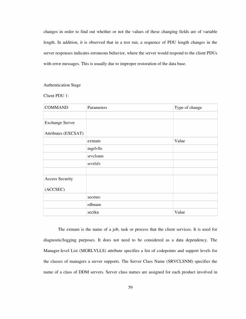
changes in order to find out whether or not the values of these changing fields are of variable
length. In addition, it is observed that in a test run, a sequence of PDU length changes in the
server responses indicates erroneous behavior, where the server would respond to the client PDUs
with error messages. This is usually due to improper restoration of the data base.
Authentication Stage
Client PDU 1:
COMMAND Parameters Type of change
Exchange Server
Attributes (EXCSAT)
extnam Value
mgrlvlls
srvclsnm
srvrlslv
Access Security
(ACCSEC)
secmec
rdbnam
sectkn Value
The extnam is the name of a job, task or process that the client services. It is used for
diagnostic/logging purposes. It does not need to be considered as a data dependency. The
Managerlevel List (MGRLVLLS) attribute specifies a list of codepoints and support levels for
the classes of managers a server supports. The Server Class Name (SRVCLSNM) specifies the
name of a class of DDM servers. Server class names are assigned for each product involved in
59

DRDA. The Server Product Release Level (SRVRLSLV) string attribute specifies the product
release level of a DDM server.
The Security Mechanism (SECMEC) specifies the security mechanism combination that
the client wants to use. For example the client can specify that it wants to use a user name and a
password with no encryption. The Relational Database Name (RDBNAM) specifies the name of a
relational database (RDB) of the server. A server can have more than one RDB. The Security
Token (SECTKN) is used by various security mechanisms. This also did not cause problems
when replaying the sequence of PDUs with that value unchanged.
The client initially requests authentication using the User ID Encryption and Password
Encryption Security Mechanism (EUSRIDPWD). This mechanism authenticates the user like the
user ID and password mechanism, but the user ID and password are encrypted and decrypted
using the encryption algorithm based on the ENCALG parameter, with encryption key length
based on the ENCKEYLEN parameter. An encryption algorithm known as the DiffieHellman
public key distribution is used to generate the connection key contained in the SECTKN
parameter, and shared private key [20]. Note that the client uses default values for the ENCALG
and ENCKEYLEN parameters and thus does not include them in the ACCSEC command. The
data fields are encrypted using Extended Binary Coded Decimal Interchange Code (EBCDIC).
Server responses: PDU 1:
OBJECT / REPLY Parameters Type of Change
EXCSATRD
60

extnam Value
mgrlvlls
srvclsnm
srvnam
srvrlslv
ACCSECRD
secmec
secchkcd
The extnam parameter is the name of a job, task or process that the application server is
running under. It is for diagnostic/logging purposes. It had no effect on the interactions that ran
between the DB2 client and server, so therefore the replay module did not need to handle it.
The Security Check Code (SECCHKCD) codifies the security information and condition
for the Security Check Reply Message (SECCHKRM).
Client PDU 2:
COMMAND Parameters Type of Change
Access Security
(ACCSEC)
secmec
rdbnam
Security Check
(SECCHK)
secmec
61

rdbnam
password
usrid
Access RDB
(ACCRDB)
rdbacccl (RDB Access Manager Class)
crrtkn (Correlation Token) Value
rdbnam Relational Database Name
prdid ProductSpecific Identifier
typdefnam Data Type Definition Name
typdefovr TYPDEF Overrides
prddta ProductSpecific Data
trgdftrt Target Default Value Return
The Password at the server (PASSWORD) specifies the password associated with the
defined enduser name on the server. The User ID at the server (USRID) specifies the user name
defined at the server. The server is responsible for any authentication and verification of the user
name.
The RDB Access Manager Class (RDBACCCL) string specifies that the SQL application
manager accesses the relational database. The Correlation Token (CRRTKN) specifies a token
that is conveyed between the client and the server for correlating the processing between the
servers. For more information see the SNA (Systems Network Architecture) LU (Logical Unit)
6.2 Reference: Peer Protocols and the DRDA reference [20]. The Productspecific Identifier
(PRDID) specifies the product release level (product version) of a DDM server. The Data Type
Definition Name (TYPDEFNAM) specifies the name of a data type definition. Examples of a
62

data type definition are Intel80X86 SQL type definition and Java SQL type definition. This
specifies the type of data representation that the server application uses when sending reply data
objects. The TYPDEF Overrides (TYPDEFOVR) parameter specifies the Coded Character Set
Identifiers (CCSIDs) that are in a named Data Type to Data Representation Definition
(TYPDEF). A CCSID is a 16bit number identifying a set of encoding scheme identifiers,
character set identifiers, code page identifiers, and other relevant information that uniquely
identifies the coded graphical representation used [20]. Examples of encoding schemes that
CCSIDs identify are EBCDIC, UNICODE and ASCII. The Productspecific Data (PRDDTA)
specifies productspecific information that is conveyed to the server if the Server Class Name
(SRVCLSNM) is not known when the ACCRDB command is issued. In addition, PRDDTA
specifies the data that must be conveyed. The Target Default Value Return (TRGDFTRT)
parameter controls whether to return the server default values in the Access Relational Database
Reply Message (ACCRDBRM) [27].
Server Response PDU 2:
OBJECT / REPLY Parameters Type of Change
ACCSECRD
secmec
secchkcd
SECCHKRM
svrcod
secchkcd
ACCRDBRM
63

svrcod
prdid
typdefnam
typdefovr
rdbinttkn Value
pkgdftcst
usrid
SQLCARD Length
The Severity Code (SVRCOD) is an indication of the severity of a condition detected
during the execution of a command. The SVRCOD can, for example, be informational, or can
indicate a warning or an error.
The RDB Interrupt Token (RDBINTTKN) is sent from the target server to the client, so
that the client can use it to interrupt a DDM command. Since in the interactions recorded between
the actual DB2 client and the server involved no interrupts, the replay module does not need to
account for any changes that occur to this parameter.
The Package Default Character Subtype (PKGDFTCST) specifies the default SQL
character subtype used if a character column is defined by and SQL CREATE or ALTER table
statement without an explicit subtype being used.
The DRDA documentation [20] states that the server may optionally return an SQL
Communication Area Reply Data (SQLCARD) object containing an SQL warning and/or server
specific connect tokens after the ACCess Relational Data Base Reply Message (ACCRDBRM).
64

So the SQLCARD reply data object returned by the target server in the second state only
gives information on the status of the server. In addition to that, if the server detects any abnormal
conditions, such as an invalid user id/password combination, in the case of DB2, the target server
will terminate the connection. The validity of our replay can be checked by running the 'replay'
command, and comparing the server's responses with the responses that were captured from the
interaction between the actual DB2 client and the target server.
5.4 Continue Query (CNTQRY) Command
The Continue Query (CNTQRY) command is invoked as a result of an SQL 'FETCH'
command. The CNTQRY command carries parameters such as an identifier which uniquely
identifies the source of the query, as well as other parameters which specify which row(s) to
fetch. One parameter of particular interest is known as the Query Instance Identifier (qryinsid).
The qryinsid parameter specifies the instance of the query in use. Its value must match the value
of the qryinsid returned in the Open Query Reply Message (OPNQRYRM), by the server, for this
instance of the query. This here is clearly a dependency on the data received from the server, and
so if our replay module does not satisfy this dependency, we will not be able to reach the next
state, as the server will most likely respond back with an error message and might terminate the
connection.
Surprisingly, by decoding and examining the packet sequences captured from the actual
client, the qryinsid had the same value, as the value we obtained from the response. As a result of
the simple setup of a single client interacting with a server, and the main realization that this work
65

stemmed from, which is letting the actual client drive the sequencing of the data, we were able to
capture the sequence then replay it using our replay module, without worrying about
dependencies. In addition to simplicity, this also has the advantage of reducing the overhead of
handling dependencies when running the tests.
5.5 Indepth analysis of DRDA Test Sequences
Since the codepoint structures described in the DDM reference are defined as an
unordered collection of elements, then using the definition of SET in the the SCL language, we
can describe the elements that reside in these codepoint structures. The OPTIONAL keyword to
describe optional elements proved essential as there are many codepoint structures which have
optional elements.
In this section, we cover 3 of the test sequences used to test the DB2 server, in detail. We
started by testing from the first state in the test sequences, then testing the second state, and so on.
This is done for each test sequence. The first and second state make up the authentication stage.
The client first sends a request to authenticate using encryption, the server informs the client that,
according to the settings (which were left to default settings), authentication using encryption is
not supported, and includes the list of supported authentication mechanisms in the reply. The
client sends out the second PDU with the credentials, using the correct authentication mechanism,
which simply encodes data objects using Extended Binary Coded Decimal Interchange Code
(EBCDIC). EBCDIC is a coded character set consisting of 8bit coded characters [20].
66

Testing the authentication stage revealed a software fault which was previously unknown
to the vendor (see section 5.6). Since the same authentication sequence is used for all sequences
and time was limited, we moved on to other areas of functionality. Most of the testing done was
using the sample sequences provided with DB2 Version 9.5 Open Beta from IBM.
Each of the 3 test sequences are described as a sequence of DRDA PDUs. PDUs which
are common between the three sequences have been given identifiers, and placed in tabular form
below. Each DRDA PDU has been assigned a list of mutations which have the potential to reveal
faults. This has been identified by studying the protocol specification, and extracting the cases
which are not covered by the specification. For each of these cases, we list the mutation strategies
involved in generating the test case(s).
Test Case Mutation(s) involved
Case A:One interesting mutation that can be applied is where the EXCSQLSIMM codepoint exists. For example in PDU where the codepoint exists with the following parameters: EXCSQLIMM PKGNAMCSN RDBCMTOK Both PKGNAMCSN and PKGSN are specified as optional elements in the DDM reference. However, one or the other is required if the other element does not exist. What if neither elements exist? What if both elements exist with values that don't correspond to the same section number? The same applies to other structures which contain these elements such as DSCSQLSTT or PRPSQLSTT.
Standard:Remove fieldSet value
Case B (invalid value mutations):QRYBLKSZ has a lower and upper limit for accepted values, namely 512 and 10485760 (10M).RDBCMTOK has legal values of either 'F0'h (false) or 'F1'h (true).
Standard:Set value
Case C:For CLSQRY requests with the following parameters: CLSQRY PKGNAMCSN QRYINSID
Standard:Set value
67

the query instance identifier, which must match the QRYINSID returned in the reply message to the Open Query Request (OPNQRY), can be changed such that its value doesn't match the value returned.
Case D:If RDBNAM is specified, its value must be the same as the value specified on the ACCRDB command for RDBNAM. What if we add a previously nonexisting RDBNAM to ACCRDB by copying it from another PDU or sequence, then change the value of RDBNAM such that it doesn't match the value of RDBNAM in ACCRDB.
Customized script
Case E (remove structure):For PDUs with the following sequence of DSS: Rqsdss EXCSQLIMM PKGNAMCSN RDBCMTOK Objdss SQLSTT
what if there was no SQLSTT OBJDSS proceeding EXCSQLIMM RQSDSS?
Standard:Remove field
PDU Descriptions:
The format of each PDU description entry is as follows:
DRDA MESSAGE
IDENTIFIER
DRDA Message Structure Potential Mutations (cases
which have the potential of
revealing faults)
Execute Immediate SQL Statement (EXCSQLIMM) Command
Executes the noncursor SQL statement sent as command data.
EXECUTE SQL IMMEDIATE Rqsdss
EXCSQLIMM A
PKGNAMCSN
RDBCMTOK
Objdss E
SQLSTT
68

RDB Commit Unit of Work (RDBCMM) Command
Commits all work performed for the unit of work. The current unit of work ends and a
new unit of work begins.
RDB COMMIT Rqsdss
RDBCMM
RDB Rollback Unit of Work (RDBRLLBCK) command
Rolls back all work performed for the current unit of work. The current unit of work
ends, and a new unit of work begins.
RDB ROLLBACK Rqsdss
RDBRLLBCK
Describe SQL Statement (DSCSQLSTT) command
Returns the definitions of either the select list or the input data variables referenced
within the specified package section.
DESCRIBE SQL STATEMENT Rqsdss
DSCSQLSTT
PKGNAMCSN
Prepare SQL Statement (PRPSQLSTT) command
Dynamically binds an SQL statement to a section in an existing relational database
(RDB) package.
69

PREPARE SQL STATEMENT Rqsdss PRPSQLSTT PKGNAMCSN Objdss SQLSTT
SELECT
Open Query (OPNQRY) command
Opens a query to a relational database.
OPEN QUERY Rqsdss
OPNQRY
PKGNAMCSN
QRYBLKSZ B
MAXBLKEXT B
Close Query (CLSQRY) command
Closes a query that an OPNQRY command opened.
CLOSE QUERY Rqsdss
CLSQRY C
PKGNAMCSN
QRYINSID
Using declared temporary tables (Sample filename: tbtemp.db2)
This sample shows how to use a declared temporary table. "A declared temporary table is
a temporary table that is only accessible to SQL statements that are issued by the application
which created the temporary table. A declared temporary table does not persist beyond the
duration of the connection of the application to the database." [21]
The following SQL statements are used:
70

CREATE USER TEMPORARY TABLESPACE DROP TABLESPACE
CREATE INDEX INSERT
DECLARE GLOBAL TEMPORARY TABLE SELECT
DESCRIBE TERMINATE
Mutation Type Mutation Count
Set Value 1142
Remove Field 1679
Permutations 1334
Total 4155
PDU 1, PDU 2 Authentication phase.
PDU 3 Rqsdss
EXCSAT
MGRLVLLS
Rqsdss
EXCSQLSET
PKGNAMCSN
Objdss E
SQLSTT SET CURRENT LOCALE
Rqsdss
EXCSQLIMM A
PKGNAMCSN
RDBCMTOK
Objdss E
SQLSTT CREATE USER TEMPORARY TABLESPACE
71

PDU 4 Rqsdss
EXCSQLIMM A
PKGNAMCSN
RDBCMTOK
Objdss E
SQLSTT DECLARE GLOBAL TEMPORARY TABLE
PDU No. DRDA Message SQL Statement (if any)
5 EXECUTE SQL IMMEDIATE SQL 'INSERT'
6 PREPARE SQL STATEMENT SQL 'SELECT'
7 OPEN QUERY
8 DESCRIBE SQL STATEMENT
9 CLOSE QUERY
10 RDB COMMIT
11 PREPARE SQL STATEMENT SQL 'SELECT'
12 OPEN QUERY
13 DESCRIBE SQL STATEMENT
14 CLOSE QUERY
15 EXECUTE SQL IMMEDIATE SQL 'DECLARE GLOBAL
TEMPORARY TABLE'
16 EXECUTE SQL IMMEDAITE SQL 'INSERT'
17 PREPARE SQL STATEMENT SQL 'SELECT'
18 OPEN QUERY
19 DESCRIBE SQL STATEMENT
20 CLOSE QUERY
21 EXECUTE SQL IMMEDIATE SQL 'CREATE INDEX'
72

PDU 22 Rqsdss
EXCSQLSTT
PKGNAMCSN
RDBCMTOK
PRCNAM
Objdss
SQLDTA
fdodsc
FDODSC
fdodta
FDODTA
PDU 23 Rqsdss
PRPSQLSTT A
PKGNAMCSN
RTNSQLDA B
Objdss E
SQLSTT SELECT
PDU 24 Rqsdss
RDBCMM
Rqsdss
DISCONNECT
Table Level Automatic Summary Table sample (Sample filename: tbast.db2)
How to use staging table for updating deferred Automatic Summary Table (AST)
This sample:
1. Creates a refreshdeferred summary table
2. Creates a staging table for this summary table
3. Applies contents of staging table to AST
73

4. Restores the data in a summary table
"A staging table allows incremental maintenance support for deferred materialized query table.
The staging table collects changes that need to be applied to the materialized query table to
synchronize it with the contents of underlying tables." [22]
The following SQL statements are used:
CREATE TABLE REFRESH
DROP SET INTEGRITY
INSERT TERMINATE
Mutation Type Mutation Count
Set Value 1400
Remove Field 1679
Permutations 1334
Total 4413
PDU 1, PDU 2 Authentication phase.
PDU 3 Potential mutations
Rqsdss EXCSAT MGRLVLLS
Rqsdss EXCSQLSET PKGNAMCSN
Objdss SQLSTT
E
Rqsdss EXCSQLIMM PKGNAMCSN RDBCMTOK
A
Objdss SQLSTT
CREATE TABLE E
74

PDU No. DRDA Message SQL Statement (if any)
4 RDB COMMIT
5 EXECUTE SQL IMMEDIATE SQL 'CREATE TABLE'
(SELECT)
6 RDB COMMIT
7 EXECUTE SQL IMMEDIATE SQL 'CREATE TABLE'
8 RDB COMMIT
9 EXECUTE SQL IMMEDIATE SQL 'SET INTEGRITY'
10 RDB COMMIT
11 EXECUTE SQL IMMEDIATE SQL 'REFRESH TABLE'
12 COMMIT
13 EXECUTE SQL IMMEDIATE SQL 'INSERT'
14 RDB COMMIT
15 PREPARE SQL STATEMENT SQL 'SELECT'
16 OPEN QUERY
17 DESCRIBE SQL STATEMENT
18 CLOSE QUERY
19 RDB COMMIT
20 EXECUTE SQL IMMEDIATE SQL 'REFRESH'
21 RDB COMMIT
PDUs 22 to 44 (inclusive), which make up the rest of the sequence, use the same DRDA message
types used from PDU 3 to PDU 21, and therefore are not presented.
Creating a Table with a Check Constraint (Sample filename: const.db2)
This sample demonstrates how to create a table with a check constraint. A table check
constraint specifies a search condition that is enforced for each row of the table on which the
table check constraint is defined. Once table check constraints are defined to the database
75

manager, an insert or update to the data within the tables is checked against the defined
constraint. Completion of the requested action depends on the result of the constraint checking
[23].
The following SQL statements are used:
CREATE TABLE INSERT DROP
Mutation Type Mutation Count
Set Value 4834
Remove Field 680
Permutations 1360
Total 6874
PDU 1, PDU 2 Authentication phase.
PDU 3 Rqsdss
EXCSAT
MGRLVLLS
Rqsdss
EXCSQLSET
PKGNAMCSN
Objdss E
SQLSTT SET CURRENT LOCALE
Rqsdss
EXCSQLIMM
PKGNAMCSN
RDBCMTOK
Objdss E
SQLSTT CREATE TABLE
76

PDU No. DRDA Message SQL Statement (if any)
4 RDB COMMIT
5 EXECUTE SQL IMMEDIATE SQL 'INSERT'
6 RDB ROLLBACK
7 EXECUTE SQL IMMEDIATE SQL 'DROP TABLE'
8 RDB COMMIT
5.6 DRDA Test Sequence Results
One critical software fault [26], previously unknown to the vendor, was found by setting
the length field value of the ACCSEC to an unsigned integer which is less than 4 (0 to 3), which
is the size of the length field plus the size of the codepoint field. This type of error usually occurs
because of the absence of a sanity check on the length field. In this case the sanity check would
be checking if the length is greater than or equal to the total size of both the length field and the
codepoint field. This caused the DB2 server to crash, leading to a denial of service. The problem
was first fixed in Version 9.1 FixPak 3 [26].
A second software fault, which was already known to the vendor, was revealed by the
framework. This fault showed up as a sideeffect of the testing and did not pertain to a specific
mutation. The vendor informed us that the fault was already fixed.
In table 5.1 we present statistics from testing 26 different sequences, throughout different
stages of the project. Since most of the test sequences used were obtained by capturing
interactions from sample sequences included in the DB2 package, the names of those sequences
in the table match the name of the sample. The test sequence 'complex' was obtained from the
77

IBM website and the tests with the name prefix 'lob' were obtained from the IBM DB2 Release
Management Team.
For some of the test sequences, the data base is set up by the sample sequence set up
script, prior to executing the sample script. The test sequence names suffixed with
'_binding_stage' are sequences captured while setting up the data base for the sequence. Test
sequence names suffixed with '_execution_stage' are sequences captured during the execution of
the SQL queries in the sample script.
78

Table 5.1 Test Results Summary
79
Test Sequence
complex 19 1018 6 72const 8 6874 39 275dbinfo 7 268 1 13lob1001 7 889 5 42lob1002 7 121 1 6lob1003 14 1266 6 56lob1008 7 121 1 6lob1019 11 247 1 11tbast 44 4413 23 207tbcompress 11 724 4 32tbcreate 8 700 4 28tbident 26 1056 6 90tbinfo 7 764 4 36tbintrig 68 1836 9 190tbload 26 1368 8 117tbloadcursor 40 696 4 33tbmerge 64 1200 6 124tbmod 125 3052 11 71tbmove 127 3924 14 91tbonlineinx 44 1322 7 62tbread_binding_stage 35 1706 9 80tbread_execution_stage 115 3211 11 74tbrunstats 11 706 4 26tbrunstats_execution_stage 6 738 4 31tbsel 14 632 3 28tbtemp 25 4155 24 354
Sequence Length
No. of Test Cases
Test Cases Generation Time (mins)
Test Run Time (mins)

Chapter 6 Conclusions and Future Work
6.1 Introduction
Throughout the course of this thesis work, we have studied the DRDA protocol
specification, and discussed the limitations of the previous version of the framework when testing
the implementation of DRDA, and how these limitations were overcome.
The languagebased lightweight testing approach, has previously been shown effective in
an academic setting, with relatively smaller protocols (fewer message types), such as X.509,
OSPF, AFP and SMB. This thesis work has shown that this technique is effective when testing
the DRDA protocol which is composed of hundreds of message types, in an industrial setting.
One important observation made is that even though there are dependencies between the
PDUs in an interaction between the DB2 client and DB2 server, these dependency data field
values did not change, provided that we restored the data base to a known state, i.e., the same
state the data base was in, prior to the execution of the interaction between the DB2 client and the
DB2 server.
A number of interactions between the DB2 client and the DB2 server were captured,
analyzed, and test cases were generated and prepared for injection, prior to the test run. Most of
the test sequences were obtained from sample interactions provided along with the DB2 software
package.
80

Two software faults, one of which was unknown to the vendor, were revealed during the
testing phase, thus demonstrating the effectiveness of the testing approach and the framework.
This shows that rules described in the DRDA specification can be covered by the mutation
strategies that this framework uses.
6.2 Contributions
Previous work has shown the ability of the testing approach and the framework, to reveal
faults in framebased protocol implementations, as well as statebased protocols, using
conformance testing data, without having to specify state dependencies as an automata or as a
grammar.
This thesis work has uncovered and addressed the following omissions in the previous
framework:
● The test plan was created manually, which has been addressed by creating a preliminary
automated test planner, in which the test planning and test case generation process have
been automated, and no user interference is required. Having said that, the new mutation
engine allows for customized mutation strategies by means of a custom mutations script,
written in an SQLlike language.
● Modifications to the markup engine were required in order to support mutations which
have an impact on length fields.
● The SCL grammar [5], SCL checkingandmodelextraction component [5] and PDU
decoder (see section 2.6.2) were modified in order to support optional elements in
structures, as well as supporting a more flexible constraints syntax used to describe the
constraints found in DRDA.
81

This set of modifications provides software testers in industry with a framework that can
be used to test implementations of protocols with minimal effort, and at the same time, achieve
significant protocol coverage.
6.3 Future Work
As part of this work, the author of this thesis has introduced an SQLlike language with
primitive syntax and keywords, used to describe mutations to be performed over the whole
sequence. Currently the mutation engine and the scripting language allow only for prefetched
values to be used in setting field values. The syntax of this language can be expanded to support
many more features such as setting the field to a value which is relative to the existing value
which was obtained from the packet capture. In addition, the framework user can also write
custom mutation scripts which perform more sophisticated mutations, once the language is
expanded.
Also as part of this work, what was simply known as the 'injector' in the previous version
of the framework, has been refactored and the logic for the TCP/IP sockethandling and
connectionhandling has been put in a separate module. This module is controlled by the replay
module, which handles the replay, including the dependencies.
Modules for other connection mechanisms can be added to the framework, such as Inter
Process Communication (IPC), or Systems Network Architecture (SNA) from IBM. Both of these
connection mechanisms are supported by DB2, in addition to TCP/IP.
82

6.4 Conclusions
In today's world, there is an everincreasing dependency on Information and
Communication Technology (ICT). ICT is now being used by governments, hospitals, banks,
businesses, etc. These information systems utilize database software to handle the databases
which hold records of employers, employees, customers, etc. This put these systems under an
increasing risk of being compromised, and as a result, money or sensitive data may be stolen.
Vandalism may also occur, tarnishing the reputation of a company.
From our study of the protocol specification, the protocol description of DRDA was
written in SCL. By describing only 200 of the 580 codepoints in the DDM reference [20], we
were able to describe 18 of 21 DDM Command Objects used by DRDA, and 19 of 22 DDM
Reply Objects and Messages used by DRDA. Thus we were able to achieve significant test
coverage of the protocol. Using this protocol description, the test planner automatically
implements the test plan, and generates the test cases.
By overcoming the limitations of the previous framework, we were capable of exercising
the DRDA protocol as implemented by the DB2 product from IBM. The testing approach and the
framework, which were shown effective in an academic setting, in previous work, has shown
effective in an industrial setting.
83

Trademarks
IBM, DB2 and DRDA are registered trademarks of International Business Machines
Corporation in the United States, other countries, or both. Java and all Javabased trademarks are
trademarks of Sun Microsystems, Inc. in the United States, other countries, or both. Other
company, product, or service names may be trademarks or service marks of others.
84

References
[1] ElFar, I.K. and Whittaker, J., “Modelbased Software Testing”, Encyclopedia on Software
Engineering , ed. J.J. Marciniak, Wiley 2001
[2] Beizer, B., Software Testing Techniques, 2nd Edition, Van Nostraad Reinhold, New York,
1990.
[3] J.R. Cordy, C.D. Halpern and E. Promislow, 1991. “TXL: A Rapid Prototyping System for
Programming Language Dialects”. Computer Languages 16,1 (January 1991), 97107.
[4] Burton S. Kaliski Jr., A Layman's Guide to a Subset of ASN.1, BER, and DER, RSA Data
Security, Inc., June 3, 1991
[5] S. Marquis, T. Dean, S. Knight, G.S.N., “SCL: A Language for Security Testing of Network
Applications”, Proc. CASCON 2005, Toronto, Oct. 2005. 155169
[6] PROTOS – Security Testing of Protocol Implementations, http://www.ee.oulu.fi/research/
ouspg/protos/, last accessed August 2008.
[7] Shu Xiao, Sheng Li, Xiangrong Wang, Lijun Deng, "Faultoriented Software Robustness
Assessment for Multicast Protocols," nca, p. 223, Second IEEE International Symposium on
Network Computing and Applications, 2003
[8] S. Zhang, T. R. Dean, S. Knight, “A Lightweight Approach to State Based Security Testing”,
Proc. CASCON 2006, Toronto, Oct. 2006. Article No. 28
[9] The Open Group, “Technical Standard DRDA, Version 3, Volume 3: Distributed Data
Management (DDM) Architecture” Publisher: The Open Group, January 2004, ISBN:
1931624429
85

[10] R. A. Demers, J. D. Fisher, S. S. Gaitonde, R. R. Sanders, “Inside IBM's Distributed Data
Management architecture – Technical”, IBM Systems Journal, September 1992, pp. 459 487
[11] A. Baker, J. Beale, B. Caswell, M. Poor, "SNORT 2.1 Intrusion Detection" Publisher: 2nd
edition Syngress; May 2004, ISBN 1931836043
[12] Ilene Burnstein, Practical Software Testing, Springer, 2003.
[13] R. Kaksonen, M. Laasko, A. Takanen, “Vulnerability Analysis of Software through Syntax
Testing”, University of Oulu, Finland, Available: http://www.ee.oulu.fi/research/ouspg/protos/
analysis/WP2000robustness/index.html, last accessed, August 2007
[14] O. Tal, T.R. Dean, G.S. Knight, Y. Turcotte, "Syntaxbased Vulnerability Testing of Frame
based Network Protocols", Proceedings of the Second Annual Conference on Privacy, Security,
and Trust, Fredericton, Canada 2004, pp. 155161.
[15] PROTOCOLS.COM Apple Talk Protocols, “Apple Talk Filing Protocol”. Available: http://
www.protocols.com/pbook/appletalk.htm#AFP
[16] J.R. Cordy, "TXL A Language for Programming Language Tools and Applications", Proc.
LDTA 2004, ACM 4th International Workshop on Language Descriptions, Tools and
Applications, Edinburg, Scotland, January 2005, pp. 331.
[17] Open Group, Protocols for X/Open PC Interworking: SMB, Version 2, October 1992,
Publisher: The Open Group, Oct. 1992, ISBN 1872630456
[18] Chuanming Jing, Zhiliang Wang, Xingang Shi, Xia Yin, Jianping Wu, "Mutation Testing of
Protocol Messages Based on Extended TTCN3," 22nd International Conference on Advanced
Information Networking and Applications (aina 2008), 2008, pp. 667 674
[19] Wireshark, available at http://www.wireshark.org/, last accessed, August 2008
86

[20] DRDA Version 3 Volume 1,2,3. Available at: http://www.opengroup.org/, last accessed,
August 2008
[21] IBM DB2 Information Center, "Declared temporary tables", available at:
http://publib.boulder.ibm.com/infocenter/db2luw/v8/index.jsp?topic=/com.ibm.db2.udb.doc/
ad/c0007024.htm, last accessed, August 2008
[22] IBM DB2 Information Center, "Creating staging tables", available at:
http://publib.boulder.ibm.com/infocenter/db2luw/v8/index.jsp?topic=/com.ibm.db2.udb.doc/
admin/t0006862.htm, last accessed, August 2008
[23] IBM DB2 Information Center, "Defining table check constraints", available at:
http://publib.boulder.ibm.com/infocenter/db2luw/v9/index.jsp?topic=/com.ibm.db2.udb.admin
.doc/doc/t0004984.htm, last accessed, August 2008
[24] Information Sciences Institute, "Transmission Control Protocol", RFC 793, September 1981.
Available at: http://www.ietf.org/rfc/rfc0793.txt, last accessed, August 2008
[25] Michael J. D., Kenneth L. C., "TCP/IP Sockets in C: Practical Guide for Programmers (The
Practical Guide Series)", publisher, Morgan Kaufmann, ISBN: 1558608265 January 2000.
[26] "DB2 engine traps if DRDA flow of the connection request is hacked". Available at:
http://www1.ibm.com/support/docview.wss?uid=swg1IZ00188, last accessed, August 2008
[27] Technical Standard DRDA, Version 2, Volume 3, Distributed Data Management (DDM)
Architecture. Available at: http://www.opengroup.org/onlinepubs/009608699/toc.pdf
[28] Y. Turcotte, O. Tal, S. Knight and T. Dean, “Universal methodology and tools for syntax
based vulnerability testing of protocol implementations”. Military Communications Conference
2004, October 2004, Volume 3, pp. 1572 1578
[29] Holt, R., Introduction to the Grok Language, 5 May 2002 http://plg.uwaterloo.ca/~holt/
87

papers/grokintro.doc, last accessed, May 2008.
[30] Haugdahl, J. Scott (1990), Inside NetBIOS, Architecture Technology Corp, ISBN
9991457348
[31] About AppleTalk Service Providers, http://developer.apple.com/documentation/mac/
NetworkingOT/NetworkingWOT64.html, last accessed, September 2008.
[32] DB2 9 for Linux UNIX and Windows, http://www306.ibm.com/software/data/db2/9/
openbeta.html, last accessed, August 2007.
[33] Programming Language, http://en.wikipedia.org/wiki/Programming_language, last accessed,
August 2008
[34] PublicKey Infrastructure (X.509) (pkix). http://www.ietf.org/html.charters/pkix
charter.html, 2004., last accessed Aug 10, 2006.
[35] A Simple Network Management Protocol (SNMP), http://www.ietf.org/rfc/rfc1157.txt, last
accessed, August 2008
[36] OSPF Version 2, http://www.ietf.org/rfc/rfc2328.txt, last accessed, August 2008
88

Appendix
Part of the DRDA Protocol Description in SCL
PDU ::= SEQUENCE { seqOfDss SEQUENCE OF Dss } <size> seqOfDss IS CONSTRAINED </size>
Dss ::= (Rqsdss | Objdss | Rpydss)
DssHeader ::= SEQUENCE { lenField INTEGER, constant INTEGER, format INTEGER, correlationIdentifier INTEGER } <size> lenField IS 2 BYTES ddmid IS 1 BYTES format IS 1 BYTES correlationIdentifier IS 2 BYTES </size> <transfer>
MATCHES { ddmid == 'D0'H } </transfer> <constraints> </constraints>
ReQueSt Data Stream Structure
Rqsdss ::= SEQUENCE { header DssHeader, cmd Command } <size> header IS SELFDEFINED cmd IS SELFDEFINED </size> <transfer> MATCHES { (header.format == '01'H | (header.format == '41'H) |
89
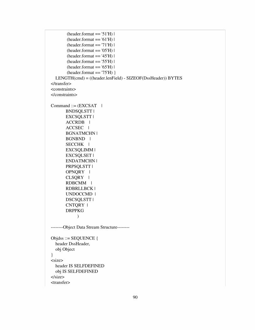
(header.format == '51'H) | (header.format == '61'H) | (header.format == '71'H) | (header.format == '05'H) | (header.format == '45'H) | (header.format == '55'H) | (header.format == '65'H) | (header.format == '75'H) } LENGTH(cmd) = ((header.lenField) SIZEOF(DssHeader)) BYTES </transfer> <constraints> </constraints>
Command ::= (EXCSAT | BNDSQLSTT | EXCSQLSTT | ACCRDB | ACCSEC | BGNATMCHN | BGNBND | SECCHK | EXCSQLIMM | EXCSQLSET | ENDATMCHN | PRPSQLSTT | OPNQRY | CLSQRY | RDBCMM | RDBRLLBCK | UNDOCCMD | DSCSQLSTT | CNTQRY | DRPPKG )
Object Data Stream Structure
Objdss ::= SEQUENCE { header DssHeader, obj Object } <size> header IS SELFDEFINED obj IS SELFDEFINED </size> <transfer>
90

MATCHES { (header.format == '03'H) | (header.format == '43'H) | (header.format == '53'H) | (header.format == '04'H) | (header.format == '44'H) | (header.format == '54'H) } LENGTH(obj) = ((header.lenField) SIZEOF(DssHeader)) BYTES </transfer> <constraints> </constraints>
Object ::= ( SQLSTT | PKGNAMCSN | SQLCARD | PKGDFTCST | RDBINTTKN | SVRCOD | SQLDTARD | SQLDARD | TRGDFTRT | PRDDTA | TYPDEFOVR | TYPDEFNAM | SECCHKCD | SECTKN | SQLRSLRD | RDBNAM | SECMEC | PRDID | SQLDTA | CRRTKN | RDBACCCL | USRID | PASSWORD | SRVRLSLV | SRVNAM | SRVCLSNM | SQLATTR | MGRLVLLS | EXTNAM | EXTDTA | EXCSATRD | ACCSECRD | QRYDSC | SQLCINRD |
91

QRYDTA )
Reply Data Stream Structure
Rpydss ::= SEQUENCE { header DssHeader, rpymsg ReplyMessage } <size> header IS SELFDEFINED rpymsg IS SELFDEFINED </size> <transfer> MATCHES { (header.format == '02'H) | (header.format == '42'H) | (header.format == '52'H) } LENGTH(ReplyMessage) = ((header.lenField) SIZEOF(DssHeader)) BYTES </transfer> <constraints> </constraints>
ReplyMessage ::= ( ABNUOWRM | ACCRDBRM | BGNBNDRM | SECCHKRM | OPNQRYRM | ENDUOWRM | ENDQRYRM | RSLSETRM | RDBUPDRM | SQLERRRM )
Prepare SQL Statement PRPSQLSTT ::= SEQUENCE { lenfield INTEGER, codepoint INTEGER, prpsqlsttparams PRPSQLSTTparams } <size> lenfield IS 2 BYTES codepoint IS 2 BYTES prpsqlsttparams IS SELFDEFINED </size> <transfer>
92

MATCHES { (codepoint == '200D'H) } LENGTH(prpsqlsttparams) = ((lenfield) 4) BYTES </transfer>
PRPSQLSTTparams ::= SET { bufinsind BUFINSIND OPTIONAL, cmdsrcid CMDSRCID OPTIONAL, monitor MONITOR OPTIONAL, pkgnamcsn PKGNAMCSN OPTIONAL, rdbnam RDBNAM OPTIONAL, rtnsqlda RTNSQLDA OPTIONAL, typsqlda TYPSQLDA OPTIONAL, pkgsn PKGSN OPTIONAL } <size> bufinsind IS SELFDEFINED cmdsrcid IS SELFDEFINED monitor IS SELFDEFINED pkgnamcsn IS SELFDEFINED pkgsn IS SELFDEFINED rdbnam IS SELFDEFINED rtnsqlda IS SELFDEFINED typsqlda IS SELFDEFINED </size> <constraints> VALUE(typsqlda) == 0 | VALUE(typsqlda) == 2 | VALUE(typsqlda) == 4 </constraints>
SQL Statement Attributes SQLATTR ::= SEQUENCE { lenfield INTEGER, codepoint INTEGER, sqlattr OCTET STRING OPTIONAL } <size> lenfield IS 2 BYTES codepoint IS 2 BYTES sqlattr IS CONSTRAINED </size> <transfer> MATCHES { codepoint == '2450'H } LENGTH(sqlattr) = ((lenfield) 4) BYTES </transfer>
93

Query Block Size QRYBLKSZ ::= SEQUENCE { lenfield INTEGER, codepoint INTEGER, val INTEGER } <size> lenfield IS 2 BYTES codepoint IS 2 BYTES val IS 4 BYTES </size> <transfer> MATCHES { (codepoint == '2114'H) } </transfer> <constraints> VALUE(val) >= 512 & VALUE(val) <= 10485760 </constraints>
Maximum Number of Extra Blocks MAXBLKEXT ::= SEQUENCE { lenfield INTEGER, codepoint INTEGER, data OCTET STRING } <size> lenfield IS 2 BYTES codepoint IS 2 BYTES data IS CONSTRAINED </size> <transfer> MATCHES { (codepoint == '2141'H) } LENGTH(data) = ((lenfield) 4) BYTES </transfer>
Query Close Implicit QRYCLSIMP ::= SEQUENCE { lenfield INTEGER, codepoint INTEGER, val INTEGER } <size> lenfield IS 2 BYTES codepoint IS 2 BYTES val IS 1 BYTES </size> <transfer>
94

MATCHES { codepoint == '215D'H } LENGTH(val) = ((lenfield) 4) BYTES </transfer> <constraints> VALUE(val) == INCLUDED 0..2 </constraints>
OPNQRY ::= SEQUENCE { lenfield INTEGER, codepoint INTEGER, opnqryparams OPNQRYparams } <size> lenfield IS 2 BYTES codepoint IS 2 BYTES opnqryparams IS CONSTRAINED </size> <transfer> MATCHES { codepoint == '200C'H } LENGTH(opnqryparams) = ((lenfield) 4) BYTES </transfer>
OPNQRYparams ::= SET { cmdsrcid CMDSRCID OPTIONAL, dupqryok DUPQRYOK OPTIONAL, maxblkext MAXBLKEXT OPTIONAL, monitor MONITOR OPTIONAL, outovropt OUTOVROPT OPTIONAL, pkgnamcsn PKGNAMCSN OPTIONAL, qryblkctl QRYBLKCTL OPTIONAL, qryblksz QRYBLKSZ, qryclsimp QRYCLSIMP OPTIONAL, qryclsrls QRYCLSRLS OPTIONAL, qryrowset QRYROWSET OPTIONAL, rdbnam RDBNAM OPTIONAL, rtnsqlda RTNSQLDA OPTIONAL, typsqlda TYPSQLDA OPTIONAL, cp214b CP214B OPTIONAL, cp2137 CP2137 OPTIONAL, pkgsn PKGSN OPTIONAL } <size> cmdsrcid IS SELFDEFINED dupqryok IS SELFDEFINED maxblkext IS SELFDEFINED monitor IS SELFDEFINED
95

outovropt IS SELFDEFINED pkgnamcsn IS SELFDEFINED qryblkctl IS SELFDEFINED qryblksz IS SELFDEFINED qryclsimp IS SELFDEFINED qryclsrls IS SELFDEFINED qryrowset IS SELFDEFINED rdbnam IS SELFDEFINED rtnsqlda IS SELFDEFINED typsqlda IS SELFDEFINED cp214b IS SELFDEFINED cp2137 IS SELFDEFINED pkgsn IS SELFDEFINED </size> <constraints> </constraints>
DUPQRYOK ::= SEQUENCE { lenfield INTEGER, codepoint INTEGER, val INTEGER } <size> lenfield IS 2 BYTES codepoint IS 2 BYTES val IS 1 BYTES </size> <transfer> MATCHES { codepoint == '210B'H } LENGTH(val) = ((lenfield) 4) BYTES </transfer> <constraints> VALUE(val) == 'F1'H | VALUE(val) == 'F0'H </constraints>
QRYBLKCTL ::= SEQUENCE { lenfield INTEGER, codepoint INTEGER, val INTEGER } <size> lenfield IS 2 BYTES codepoint IS 2 BYTES val IS 1 BYTES </size>
96

<transfer> MATCHES { codepoint == '2132'H } LENGTH(val) = ((lenfield) 4) BYTES </transfer> <constraints> VALUE(val) == '2418'H | VALUE(val) == '2417'H | VALUE(val) == '2410'H </constraints>
Continue Query CNTQRY ::= SEQUENCE { lenfield INTEGER, codepoint INTEGER, cntqryparams CNTQRYparams } <size> lenfield IS 2 BYTES codepoint IS 2 BYTES cntqryparams IS CONSTRAINED </size> <transfer> MATCHES { (codepoint == '2006'H) } LENGTH(cntqryparams) = ((lenfield) 4) BYTES </transfer> <constraints> VALUE(qryinsid) == OPNQRYRM.qryinsid </constraints>
CNTQRYparams ::= SET { cmdsrcid CMDSRCID OPTIONAL, maxblkext MAXBLKEXT OPTIONAL, monitor MONITOR OPTIONAL, pkgnamcsn PKGNAMCSN OPTIONAL, qryblkrst QRYBLKRST OPTIONAL, qryblksz QRYBLKSZ, qryinsid QRYINSID, qryrownbr QRYROWNBR OPTIONAL, qryrowset QRYROWSET OPTIONAL, qryrowsns QRYROWSNS OPTIONAL, qryrtndta QRYRTNDTA OPTIONAL, qryscrorn QRYSCRORN OPTIONAL, rdbnam RDBNAM OPTIONAL, rtnextdta RTNEXTDTA OPTIONAL, freprvref FREPRVREF OPTIONAL, pkgsn INTEGER OPTIONAL } <size>
97

cmdsrcid IS SELFDEFINED maxblkext IS SELFDEFINED monitor IS SELFDEFINED pkgnamcsn IS SELFDEFINED qryblkrst IS SELFDEFINED qryblksz IS SELFDEFINED qryinsid IS SELFDEFINED qryrownbr IS SELFDEFINED qryrowset IS SELFDEFINED qryrowsns IS SELFDEFINED qryrtndta IS SELFDEFINED qryscrorn IS SELFDEFINED rdbnam IS SELFDEFINED rtnextdta IS SELFDEFINED freprvref IS SELFDEFINED pkgsn IS 2 BYTES </size>
Close Query CLSQRY ::= SEQUENCE { lenfield INTEGER, codepoint INTEGER, clsqryparams CLSQRYparams } <size> lenfield IS 2 BYTES codepoint IS 2 BYTES llcp IS SELFDEFINED clsqryparams IS SELFDEFINED </size> <transfer> MATCHES { codepoint == '2005'H } LENGTH(clsqryparams) = ((lenfield) 4) BYTES </transfer>
CLSQRYparams ::= SET { cmdsrcid CMDSRCID OPTIONAL, monitor MONITOR OPTIONAL, pkgnamcsn PKGNAMCSN OPTIONAL, qryclsrls QRYCLSRLS OPTIONAL, qryinsid QRYINSID, rdbnam RDBNAM OPTIONAL, pkgsn INTEGER OPTIONAL } <size> cmdsrcid IS SELFDEFINED
98

monitor IS SELFDEFINED pkgnamcsn IS SELFDEFINED pkgsn IS 2 BYTES qryclsrls IS SELFDEFINED qryinsid IS SELFDEFINED rdbnam IS SELFDEFINED </size> <transfer> </transfer> <constraints> </constraints>
Package Name and Consistency Token PKGNAMCT ::= SEQUENCE { lenfield INTEGER, codepoint INTEGER, pkgnamctparams PKGNAMCTparams } <size> lenfield IS 2 BYTES codepoint IS 2 BYTES pkgnamctparams IS SELFDEFINED </size> <transfer> MATCHES { codepoint == '2112'H } </transfer>
PKGNAMCTparams ::= SET { pkgcnstkn OCTET STRING, scldtalen1 SCLDTALEN OPTIONAL, pkgid OCTET STRING, scldtalen2 SCLDTALEN OPTIONAL, rdbcolid OCTET STRING, scldtalen3 SCLDTALEN OPTIONAL, rdbnam OCTET STRING } <size> pkgcnstkn IS 8 BYTES scldtalen1 IS SELFDEFINED pkgid IS CONSTRAINED scldtalen2 IS SELFDEFINED rdbcolid IS CONSTRAINED scldtalen3 IS SELFDEFINED rdbnam IS CONSTRAINED </size> <transfer>
99

LENGTH(pkgid) = ((18*( (PKGNAMCT.lenfield) == 66)) | ((scldtalen1)*((PKGNAMCT.lenfield)!=66))) BYTES LENGTH(rdbcolid) = ((18*( (PKGNAMCT.lenfield) == 66)) | ((scldtalen2)*((PKGNAMCT.lenfield)!=66))) BYTES LENGTH(rdbnam) = ((18*( (PKGNAMCT.lenfield) == 66)) | ((scldtalen3)*((PKGNAMCT.lenfield)!=66))) BYTES </transfer> <constraints> VALUE(LENGTH(pkgid)) >= 18 VALUE(LENGTH(pkgid)) <= 255 </constraints>
100