an end-effector based upper-limb rehabilitation robot ... · an end-effector based upper-limb...
TRANSCRIPT

An End-Effector Based Upper-Limb RehabilitationRobot: Preliminary Mechanism Design
Yekaterina Ponomarenko, Bauyrzhan Aubakir, Shahid Hussain and Almas ShintemirovDepartment of Robotics and Mechatronics
Nazarbayev University
Astana, Kazakhstan, 010000
Emails: [email protected], [email protected]
Abstract—Loss of upper limb function often appears afterstroke. In this paper the 3D mechanism design for an elec-tromagnetically powered end-effector based robotic manipulatorwas developed for post-stroke physical therapy. The proposedsystem delivers a dexterous performance and has a novelty amongend-effector based rehabilitation robots. Its design incorporatescurved links, which expand the manipulators performance abili-ties, and, as a result, increase the range of types of rehabilitationtherapies. The proposed robotic manipulator can provide apatient with three and two degrees of freedom in shoulder andelbow joints, respectively. It has seven degrees of freedom, andis capable of 7 kg payload. The design of manipulators linkageswas optimized to decrease the weight of the system.
Index Terms—Rehabilitation, upper limb, robots, stroke
I. INTRODUCTION
Neurological impairment after stroke frequently leads to
the loss of the motor skills in the limb that affects the
patients ability to perform activities of daily life. Training and
rehabilitation therapy offer an opportunity for motor recovery
[1]–[3].
Studies show that human brain is adaptable to changing
demands and capable of self-reorganization. Training with
specific exercises is necessary to induce nervous systems
changes, provoke motor plasticity and, as a result, improve
motor recovery [4]. Thus, to restore motor capabilities, the
affected limb has to be exercised [5].
A therapy regime must be intensive, repetitive and of
long duration. Conventional rehabilitation therapies are effort
intensive. Physiotherapists have to assist manually the patient
to conduct the exercises [6]. Training is exhausting for the
therapist and, as a result, time limited [7]. This fact stimulates
new approaches in rehabilitation in a way it becomes more
effective and prolonged.
Robot-aided therapy is an emerging part of post-stroke
rehabilitation care [8], [9]. Robotic exercisers provide intensive
motor therapy, which can be performed in a repetitive, accurate
and controllable manner [10], [11]. Moreover, the therapeutic
action of the robot can be adjusted to the patients motor
abilities [12], [13]. Training with mechatronic systems has
mostly shown encouraging outcomes of rehabilitation [5], [14],
[15]. Robotic devices may offer the required amount of motor
practice and reduce the effort of therapists conducting the
rehabilitation procedure [16], [17]. This paper focuses on the
upper limb rehabilitation.
Several rehabilitation robots for the upper limb have been
proposed. In general, there are two types of designs: exoskele-
ton [18]–[20] and robotic end-effector based [21] systems.
In end-effector based robotic exercisers a patients hand is
attached to a hand-holder having trajectories that simulate
natural movements of the arm [16]. Examples of the end-
effector based robots include MIT Manus [22], [23], ARM
Guide [24], MIME [21].
The aim of this project was to design an end-effector based
robot for upper extremity rehabilitation. The paper is organized
as follows: Section II presents the design requirements, the
concept and the mechanical model of the rehabilitation system.
Section III illustrates and discussed the results, while Section
IV comments on conclusion.
II. METHODOLOGY
A. Proposed System Requirements
A robotic device is required to provide exercise to the
patients arm in the required ranges of motion. The patient
receives constant assistance, with the hand and wrist being
attached to the end of the robotic arm and guided on a specific
trajectory. The system is designed to support the weight of the
patients upper limb, while performing exercises.
The proposed robotic device should provide a patient with
five independent DOFs in the upper limb including, shoul-
der flexion and extension movement, shoulder abduction and
adduction movement, shoulder rotation movement around its
axis, elbow flexion and extension movement and shoulder
rotation movement around its axis. The device needs to be
designed to cover the workspace of a half-sphere with the
radius of a patients arm length, centered at the shoulder of a
patient. Unilateral training is required at a time.
The robotic device needs to be bidirectional, with enough
number of DOFs and appropriate link structure in order to
meet the requirements mentioned above. The requirements for
a robotic rehabilitation device also include comfort, safety and
low complexity.
B. Mechanical Design
The proposed system (Fig. 1) was designed as a stationary,
end-effector based robotic device comprising of a basement
A, six serial links E-J and a hand-holder plate N. The system
design incorporates two curved links H and I. Link J and the
Mecatronics-2014-Tokyo November 27-29, 2014, Tokyo, Japan
978-1-4799-5717-0/14/$31.00 ©2014 IEEE 168
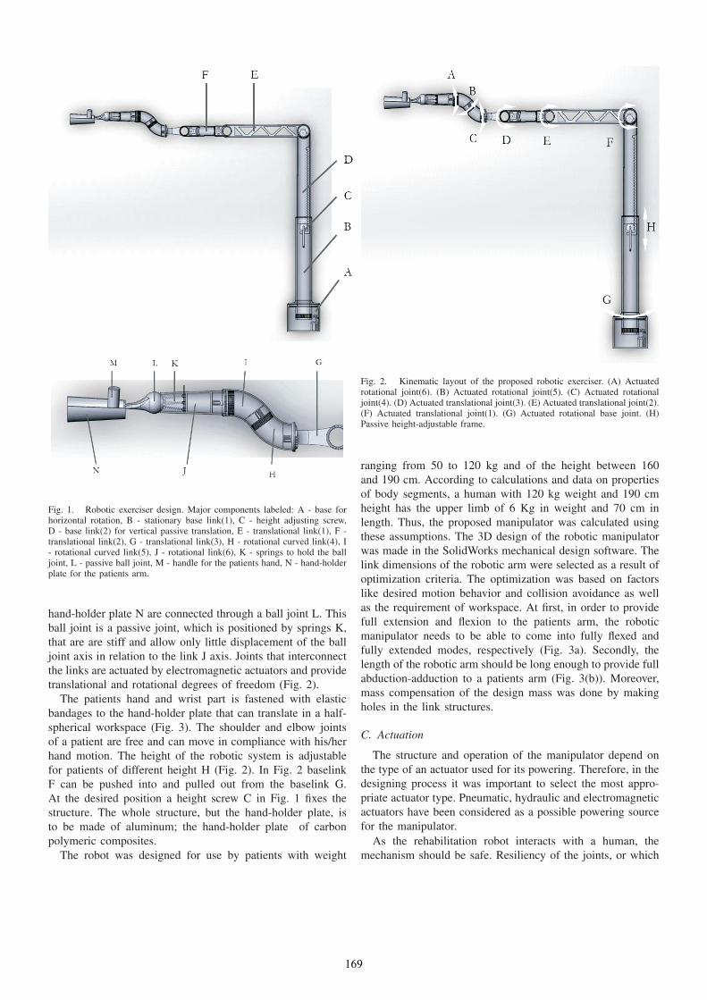
Fig. 1. Robotic exerciser design. Major components labeled: A - base forhorizontal rotation, B - stationary base link(1), C - height adjusting screw,D - base link(2) for vertical passive translation, E - translational link(1), F -translational link(2), G - translational link(3), H - rotational curved link(4), I- rotational curved link(5), J - rotational link(6), K - springs to hold the balljoint, L - passive ball joint, M - handle for the patients hand, N - hand-holderplate for the patients arm.
hand-holder plate N are connected through a ball joint L. This
ball joint is a passive joint, which is positioned by springs K,
that are are stiff and allow only little displacement of the ball
joint axis in relation to the link J axis. Joints that interconnect
the links are actuated by electromagnetic actuators and provide
translational and rotational degrees of freedom (Fig. 2).
The patients hand and wrist part is fastened with elastic
bandages to the hand-holder plate that can translate in a half-
spherical workspace (Fig. 3). The shoulder and elbow joints
of a patient are free and can move in compliance with his/her
hand motion. The height of the robotic system is adjustable
for patients of different height H (Fig. 2). In Fig. 2 baselink
F can be pushed into and pulled out from the baselink G.
At the desired position a height screw C in Fig. 1 fixes the
structure. The whole structure, but the hand-holder plate, is
to be made of aluminum; the hand-holder plate of carbon
polymeric composites.
The robot was designed for use by patients with weight
Fig. 2. Kinematic layout of the proposed robotic exerciser. (A) Actuatedrotational joint(6). (B) Actuated rotational joint(5). (C) Actuated rotationaljoint(4). (D) Actuated translational joint(3). (E) Actuated translational joint(2).(F) Actuated translational joint(1). (G) Actuated rotational base joint. (H)Passive height-adjustable frame.
ranging from 50 to 120 kg and of the height between 160
and 190 cm. According to calculations and data on properties
of body segments, a human with 120 kg weight and 190 cm
height has the upper limb of 6 Kg in weight and 70 cm in
length. Thus, the proposed manipulator was calculated using
these assumptions. The 3D design of the robotic manipulator
was made in the SolidWorks mechanical design software. The
link dimensions of the robotic arm were selected as a result of
optimization criteria. The optimization was based on factors
like desired motion behavior and collision avoidance as well
as the requirement of workspace. At first, in order to provide
full extension and flexion to the patients arm, the robotic
manipulator needs to be able to come into fully flexed and
fully extended modes, respectively (Fig. 3a). Secondly, the
length of the robotic arm should be long enough to provide full
abduction-adduction to a patients arm (Fig. 3(b)). Moreover,
mass compensation of the design mass was done by making
holes in the link structures.
C. Actuation
The structure and operation of the manipulator depend on
the type of an actuator used for its powering. Therefore, in the
designing process it was important to select the most appro-
priate actuator type. Pneumatic, hydraulic and electromagnetic
actuators have been considered as a possible powering source
for the manipulator.
As the rehabilitation robot interacts with a human, the
mechanism should be safe. Resiliency of the joints, or which
169

(a) (b)
Fig. 3. Workspace of the robot. (a) Side View. (b) Top view. (A) and (D) Full shoulder extension-flexion. (B) and (C) Full elbow extension-flexion. (E) and(F) Full shoulder abduction-adduction.
is called back-drivability, is a crucial characteristic for the
safe robotic-arm operation around people. Back-drivable hy-
draulic/pneumatic actuators are either under development, or
complicated. Therefore, electromagnetic actuators for the joint
powering have been selected.
Selection of the joint motors is done according to torque
level that is required to drive specified links or end effector.
Fig. 4 shows the simplified representation of the six link
robotic manipulator for beam deflection analysis. Here M is
the required torque for the translational joints D-F (Fig. 2)
which needs to be calculated. The weight of the robotic arm
W is assumed to be uniformly distributed; whereas the weight
of the patients upper limb Wh is partly uniformly distributed,
which resides on the hand-plate. The rest part of the arm which
is free in space as a point mass L. Length l and mass m of
the structure is considered to be from the attachment of the
considered link - stationary point - to the end-effector.
The beam deflection analysis equations are derived as
follows:
q(x) =−M(x− 0)−2 +R(x− 0)−1 −W (x− 0)0−Whand(x− (l − lhand))
0 − L(x− 1)−1;(1)
V (x) =−M(x− 0)−1 +R(x− 0)0 −W (x− 0)1−Whand(x− (l − lhand))
1 − L(x− 1)0;(2)
M(x) =−M(x− 0)0 +R(x− 0)1 − W
2(x− 0)2−
Whand
2(x− (l − lhand))
2 − L(x− 1)1.
(3)
Here, equations (1) and (2) represent loading and shear func-
tions, respectively, equation (3) expresses a moment function.
Analysis of equations (1) - (3) at the end of the manipulator
yields the following equations:
V (l+) = R−Wl − L−Whlhand = 0; (4)
M(l+) = −M +Rl − W
2l2 − Whand
2l2hand = 0. (5)
Here, M is the torque transmitted by the associated joint, Ris the reaction force at the joint, W is the weight supported
by the associated joint, Whand is the weight of the part of
the patients arm that resides on the hand-holder plate, lhandis the length of the part of the patients arm that resides on
the hand-holder plate and l is the length of the robotic arm
supported by the joint.
The required torques for the rotational joints A-C and base
joint G (Fig. 2) are calculated in a different manner using the
following equations, that provide rotational motion not in the
170

Fig. 4. Beam deflection analysis. Moment calculations.
vertical plane, but in the horizontal:
T = Iα; (6)
I = mr2, (7)
where α is the angular acceleration (assumed to be π radians
per second squared), I is the moment of inertia, m is the mass
rotated by the joint, r is the radius of rotation.
III. RESULTS AND DISCUSSION
The electromagnetically actuated robotic manipulator de-
sign features a basement, two basement links, a height screw,
six serial links interconnected by tree rotary joints in the
vertical plane (Fig. 3) and four rotary joints in the horizontal
plane, a passive ball joint (Fig. 3), springs and a hand-holder
plate. The total length of the arm from the joint(1) to the end
of the hand-holder is 140 mm. The structure is to be produced
of aluminum and carbon polymeric composites. Specifying the
material type in the SolidWorks 3D CAD software the mass
of the entire robotic system is calculated to be 5.84 kg.The robotic manipulator is fixed on the floor and a patient
sits in the front of it. It is designed for the people with weight
between 50 and 120 kg and height between 160 and 190 cm.
The patients hand enfolds the handle M (Fig. 3) on the hand-
holder plate and follows the path specified by the end-effector.
The robotic arm has 7 DOF and can exert bidirectional forces,
while providing a patient with 3 DOF in shoulder and 2 DOF
in elbow. The workspace of the robot is a half sphere in
the front of a patient, centered at his exercised shoulder. The
workspace has the radius of the patients arm length and the
robotic manipulator is able to cover the workspace for the
patient with arm length of 70 cm (Fig. 3).
Fig. 5. Examples exercisers that could be performed by the robotic exerciser,because it has curved links in its design.
The novelty of the proposed rehabilitation robot for the
upper limb is its ability to revolve the patients arm, while
following the desired path. This is possible due to introducing
curved links into the design. When joint C (Fig. 2) rotates
link H (Fig. 3) and joint B (Fig. 2) does not rotate, link I
(Fig. 3) revolves around the axis of joint C (Fig. 2) and, as
a result revolves the hand-holder plate with the patients arm.
At the same time, to not twist the patients wrist joint A (Fig.
2) rotates in the opposite direction of rotation of joint C (Fig.
2). Examples of the paths described above are on Fig. 5.
The robotic manipulator with all included equipment such as
actuators, joints, fixed on the floor and balanced. The joints are
actuated separately and, therefore, are independent in motion.
High dexterity of the manipulator arm (Figs. 2 and 3) allows
the robot to suit patients with different motor impairments.
The robotic manipulator is able to provide a patient with
complex movements of full arm extension-flexion, abduction-
adduction, as well as, operate in narrow, confined workspace
area. Its ability to perform revolving motion of the arm, while
conducting the exercises (Fig. 5), can be advantageous for the
patients physical therapy. As a result, wider range of exercises
makes the rehabilitation of the upper limb more effective.
The edges of the robotic structure are filleted and, therefore,
will not injure the skin of the patient. The fixators are elastic
and, therefore, will not interfere with the blood circulation of
the patient. A flexible passive ball joint displaces when the
wrist part of the patient arm to band and prevents the patients
arm from feeling any discomfort.
IV. CONCLUSION
In this paper, an end-effector based robotic manipulator for
upper limb rehabilitation was developed. The purpose of which
is to enhance the manual therapeutic training. It is provides
a patient with 3 DOF in shoulder and 2 DOF in elbow,
and is capable to manipulate a payload of 7 kg. From the
specifications mentioned above, the robotic manipulator meets
all design requirements raised in Section II. It is powered by
electromagnetic actuators, with justified pay load and dexterity.
From the end-effector based rehabilitation robots available
on market, proposed design for the robotic manipulator has
171

particular advantages for the actuation and high range of
workspace.
REFERENCES
[1] N. Bayona and et al., “The role of task-specific training in rehabilitationtherapies,” Topics in Stroke Rehabilitation, vol. 12, no. 3, pp. 58–65,2005.
[2] R. Bonita and R. Beaglehole, “Recovery of motor function after stroke,”Stroke, vol. 19, 1988.
[3] S. Cramer and J. Riley, “Neuroplasticity and brain repair after stroke.”Current Opinion in Neurology, vol. 21, no. 1, pp. 76–82, 2008.
[4] B. D and N.HJ, “Cross-modal plasticity: where and how?” Nat. Rev.Neurosci, vol. 3, pp. 443–452, 2002.
[5] G. Kwakkel, B. Kollen, and R. Wagenaar, “Long term effects of intensityof upper and lower limb training after stroke: a randomised trial,”Journal of Neurology Neurosurgery and Psychiatry, vol. 72, no. 4, pp.473–479, 2002.
[6] G. Kwakkel and et al., “Intensity of leg and arm training after primarymiddle-cerebral-artery stroke: a randomised trial,” Lancet, vol. 354, no.9174, pp. 191–196, 1999.
[7] N. L. Holder and et al., “Cause, prevalence, and response to occupationalmusculoskeletal injuries reported by physical therapists and physicaltherapist assistants,” Physical Therapy, vol. 79, no. 7, pp. 642–652, 1999.
[8] S. Hussain, S. Q. Xie, and G. Liu, “Robot assisted treadmill training:Mechanisms and training strategies,” Medical Engineering & Physics,vol. 33, no. 5, pp. 527–533, 2011.
[9] D. J. Reinkensmeyer, J. Emken, and S. Cramer, “Robotics, motorlearning, and neurologic recovery,” Annual Review of Biomedical En-gineering, vol. 6, pp. 497–525, 2004.
[10] L. Kahn and et al., “Robot-assisted movement training for the stroke-impaired arm: Does it matter what the robot does?” Journal of Rehabil-itation Research and Development, vol. 43, no. 5, pp. 619–629, 2006.
[11] L. Marchal-Crespo and D. Reinkensmeyer, “Review of control strategiesfor robotic movement training after neurologic injury,” Journal ofNeuroEngineering and Rehabilitation, vol. 6, no. 1, 2009.
[12] J. L. Emken and D. Reinkensmeyer, “Robot-enhanced motor learning:Accelerating internal model formation during locomotion by transientdynamic amplification,” IEEE Transactions on Neural Systems andRehabilitation Engineering, vol. 13, no. 1, pp. 33–39, 2005.
[13] R. J. Sanchez and et al., “Automating arm movement training followingsevere stroke: Functional exercises with quantitative feedback in agravity-reduced environment,” IEEE Transactions on Neural Systemsand Rehabilitation Engineering, vol. 14, no. 3, pp. 378–389, 2006.
[14] R. Colombo and et al., “Robotic techniques for upper limb evaluationand rehabilitation of stroke patients,” IEEE Transactions on NeuralSystems and Rehabilitation Engineering, vol. 13, no. 3, pp. 311–324,2005.
[15] S. E. Fasoli and et al., “Effects of robotic therapy on motor impairmentand recovery in chronic stroke,” Archives of Physical Medicine andRehabilitation, vol. 84, no. 4, pp. 477–482, 2003.
[16] G. Kwakkel, B. J. Kollen, and H. Krebs, “Effects of robot-assistedtherapy on upper limb recovery after stroke: A systematic review,”Neurorehabilitation and Neural Repair, vol. 22, no. 2, pp. 111–121,2008.
[17] P. Lum and et al., “Robot-assisted movement training compared withconventional therapy techniques for the rehabilitation of upper-limbmotor function after stroke,” Archives of Physical Medicine and Re-habilitation, vol. 83, no. 7, pp. 952–959, 2002.
[18] A. Stienenw and et al., “Design of a rotational hydroelastic actuator fora powered exoskeleton for upper limb rehabilitation,” IEEE Transactionson Biomedical Engineering, vol. 57, no. 3, pp. 728–735, 2010.
[19] T. Sugar and et al., “Design and control of RUPERT: a device forrobotic upper extremity repetitive therapy,” IEEE Transactions on NeuralSystems and Rehabilitation Engineering, vol. 15, no. 3, pp. 336–346,2007.
[20] H. Lo and S. Xie, “Exoskeleton robots for upper-limb rehabilitation:state of the art and future prospects,” Medical Engineering & Physics,vol. 34, pp. 261–268, 2011.
[21] P. Lum and et al., “MIME robotic device for upper-limb neuroreha-bilitation in subacute stroke subjects: a follow-up study,” Journal ofRehabilitation Research and Development, vol. 43, no. 5, pp. 631–642,2006.
[22] L. Masia and et al., “Design and characterization of hand module forwhole-arm rehabilitation following stroke,” IEEE/ASME Transactions onMechatronics, vol. 12, no. 4, pp. 399–407, 2007.
[23] H. Krebs and et al., “Robot-aided neurorehabilitation: a robot for wristrehabilitation,” IEEE Transactions on Neural Systems and RehabilitationEngineering, vol. 15, pp. 327–335, 2007.
[24] D. J. Reinkensmeyer, J. Dewald, and W. Rymer, “Guidance-basedquantification of arm impairment following brain injury: a pilot study,”IEEE Transactions on Rehabilitation Engineering, vol. 7, pp. 1–11,1999.
172