an individual perspective - perceptually realistic depiction …€¦ · · 2015-12-31an...
TRANSCRIPT

Slide 1
Lehrstuhl fürMediengestaltung
An Individual Perspective - Perceptually Realistic Depiction Of Human Figures
Martin Zavesky, Jan Wojdziak, Kerstin Kusch, Daniel Wuttig, Ingmar S. Franke and Rainer Groh
VISAPP 2011, 5. March - 7. March 2011
Fakultät Informatik, Institut für Software- und Multimediatechnik

Slide 2
This publication is supported by the European Union and the Free State of Saxony, funded by the European Social Fund (ESF)

Slide 3
Übersicht
Motivation
General approach
Multi-perspective solutions
OBPC
CBPC
Discussion
Study
Future work
Conclusion

Slide 4
Motivation
The common computer graphics camera model creates mono-perspective images.
Mono-perspective images do not fulfil the expectations of natural viewing behaviour [1].
Change of figures‘ proportion and orientation due to the projection
Fig. 1: Mono-perspective image, aperture angle 120 degree

Slide 5
General approach
Fig. 2: The Tribute Money, Tommaso di Ser Cassai (Masaccio), 1425-1428
Study of artistic solutions for projective problems
Especially study of human depiction in arts and computer graphics

Slide 6
General Approach
[S]
[P0] [PA]
[B][A]
[PB]
[H]
Fig. 3: Sketch of ’The Tribute Money’, Tommaso di Ser Cassai (Masaccio), horizontal [H] and sagittal [S] line, princi-ple vanishing point [P0], additional principle vanishing points [PA] and [PB] of persons [A] and [B]
Artists solved projective problems by using of multiperspective imaging.
Especially human figures were displayed with its own perspective. This leads to perceptual realism
Perceptual realism means to integrate the characteristics of human perception into the imaging process and the image.

Slide 7
Multi-perspective solutions
Multi-perspective imaging seems to be a valuable way
Non-photorealistic rendering shows an wide range of possible approaches
[2] [3]
[4] [5]
[6]
Fig. 4: Multi-perspective NPR solutions

Slide 8
OBPC
[OA]
[C]
[OB] [OC]
[DA] [DB] [DC]
[V]
[I]
Object based Perspective Correction
1. Specify the pivot point of the object in
the local camera coordinate system.
2. Compute the shear factors from that
relative position
3. Compute the rotation angles
4. Rotate the object around x- and y-axis
according to the rotation angles
5. Shear the object with a shear matrix
based on the computed shear factorsFig. 5: The system camera renders [OB], [OC] excluding the object [OA] attached to the object camera. For size constancy the
image plane [IA] of the object camera is shifted right up to the intersection [S]

Slide 9
OBPC
Object based Perspective Correction
1. Specify the pivot point of the object in
the local camera coordinate system.
2. Compute the shear factors from that
relative position
3. Compute the rotation angles
4. Rotate the object around x- and y-axis
according to the rotation angles
5. Shear the object with a shear matrix
based on the computed shear factors
[A] [B][C][D]
a
bFig. 6: Monoperspective image (a), result of the OBPC on colored figures (b)

Slide 10
OBPC
Object based Perspective Correction
1. Specify the pivot point of the object in
the local camera coordinate system.
2. Compute the shear factors from that
relative position
3. Compute the rotation angles
4. Rotate the object around x- and y-axis
according to the rotation angles
5. Shear the object with a shear matrix
based on the computed shear factors

Slide 11
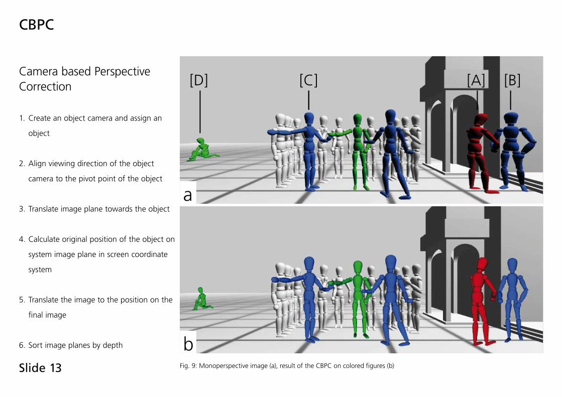
CBPC
Camera based Perspective Correction
1. Create an object camera and assign an
object
2. Align viewing direction of the object
camera to the pivot point of the object
3. Translate image plane towards the object
4. Calculate original position of the object on
system image plane in screen coordinate
system
5. Translate the image to the position on the
final image
6. Sort image planes by depth
[OA]
[C]
[OB] [OC]
[IA]
[IB]
[V][VA]
[S]
Fig. 7: The system camera renders [OB], [OC] excluding the object [OA] attached to the object camera. For size constancy the image plane [IA] of the object camera is shifted right up to the intersection [S]

Slide 12
image of object camera image of system cameraresulting image
CBPC
Fig. 8: Composition of different views in the CBPC
Slide 13
CBPC
[A] [B][C][D]
a
b
Camera based Perspective Correction
1. Create an object camera and assign an
object
2. Align viewing direction of the object
camera to the pivot point of the object
3. Translate image plane towards the object
4. Calculate original position of the object on
system image plane in screen coordinate
system
5. Translate the image to the position on the
final image
6. Sort image planes by depth
Fig. 9: Monoperspective image (a), result of the CBPC on colored figures (b)

Slide 14
CBPC
Camera based Perspective Correction
1. Create an object camera and assign an
object
2. Align viewing direction of the object
camera to the pivot point of the object
3. Translate image plane towards the object
4. Calculate original position of the object on
system image plane in screen coordinate
system
5. Translate the image to the position on the
final image
6. Sort image planes by depth

Slide 15
Both approaches have individual advantages and disadvantages
Comparison
a b c
d e f
Fig. 10: Details: (a+d ) mono-perspective rendered with standard camera, (b+e ) using OBPC, (c+f ) using CBPC
Mono-perspective OBPC CBPC

Slide 16
Both approaches have individual advantages and disadvantages
Each approach complements the other
Both may be used parallel in scenes without interference
Discussion
advantages disadvantages
Object-BasedPerspectiveCorrection
Camera-BasedPerspectiveCorrection
unmodified camera
adjustable
objectintersection
no objecttransformation
no objectintersection
modifiedcamera
non-adjustable
transformationnecessary
Fig. 11: Comparison of OBPC and CBPC

Slide 17
Study
Study on the perception differences of mono- and multiperspective relative to the natural viewer perception
Examination of the real scene orientation of human figures and its perception by the viewer
First cognition: Difference between percieved an intended orientation
F1 F2
Fig. 14: Comparison of percived an intended figure orientation (orginal orientation -30 degree)
F1 F1
Fig. 12: Scene with rotated figures (-30 degree), mono-perspective image
Original orientation
Mono-perspective
Photo
OBPC
F1 F2
Fig. 13: Scene with rotated figures (-30 degree), multi-perspective image

Slide 18
Solve light and shadowing problems
Development of CBPC adjustabilty
Further research on orientation to determine ideal parameters of the algoritms to create perceptually realistic images
Future work

Slide 19
Conclusion
Perceptual realism could be achieved by multi-perspective images based on perspective projection enhanced by characteristics of visual perception and techniques of Renaissance painting.
OBPC and CBPC differ in its way of solving distortion and misalignment.Both approaches use multi-perspective imaging to adapt the image to the human viewing behavoiur.
This could enhance an adapted depiction og objects especially of human figures.

Slide 20
Thank you for your attention!
This publication is part of the inovation promotion of Martin Zavesky and Jan Wojdziak which is supported by the European Union an the Freestate of Saxony funded by the European Social Fund (ESF).
Questions andanswers

Slide 21
References
[1] I. S. Franke, S. Pannasch, J. R. Helmert, R. Rieger, R. Groh, und B. M. Velichkovsky, “Towards attention-centered interfaces: An aesthetic evaluation of perspective with eye tracking,” ACM Trans. Multimedia Comput. Commun. Appl., Bd. 4, S. 1-13, 2008.[2] D. Zorin und A. H. Barr, “Correction of geometric perceptual distortions in pictures,” in SIGGRAPH ‚95: Proceedings of the 22nd annual conference on Computer graphics and interactive techniques, S. 257–264, 1995.[3] P. Coleman und K. Singh, “Ryan: rendering your animation nonlinearly projected,” in NPAR ‚04: Proceedings of the 3rd international symposium on Non-photorealistic animation and rendering, S. 129-156, 2004.[4] P. Rademacher und G. Bishop, “Multiple center of projection images,” in Proceedings of the 25th annual conference on Computer graphics and interactive techniques, S. 199–206, 1998.[5] K. Singh, “A Fresh Perspective,” in Proceedings of Graphics Interface 2002, S. 17-24, 2002.[6] M. Agrawala, D. Zorin, und T. Munzner, “Artistic Multiprojection Rendering,” in Proceedings of the Eurographics Workshop on Rendering Techniques 2000, S. 125-136, 2000.

Slide 22
Standard projection Shearing Shearing and rotation
Standard projection Shearing Shearing and rotation
OBPC
Object based Perspective Correction
Undistorted depiction of curved surfaced objects
Integration of multiple additional principle vanishing points

Slide 23
OBPC
Direct geometry manipulation
Rendering by standard cg camera model
Rotation an shearing depending on the realtion between camera and object
Shearing of rotated objects
Parts of OBPC
Y
Z
Y
Z
Y
Z
Rotation of objects
Original scene

Slide 24
Matrix notationPoint of object = [P]Corrected Point = [P’]
Transformation matrix of object = [O]Transformation matrix of object (modified) = [O’]
Transformation matrix of camera = [K]Transformation matrix of camera (modified) = [K’]
Relative position of the object to the camera = PO
Shearmatrix defined by shear factors = [S]Rotation relative to local z-axis = [Rz]Rotation relative to local x-axis = [Rx]
[P’] = [O’] * [K’] * [S] * [Rx] * [Rz] * [K’]-1 * [O’]-1 * [P]
[K] [K’][K’]-1
[O’]-1
[O’]
[P]
[O]
[P’]
PO [R ]X [R ]Z[S]
BerechnungEingabe
OBPC
Input
Calculation
Slide 25
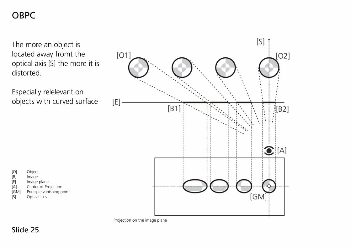
OBPC
The more an object is located away fromt the optical axis [S] the more it is distorted.
Especially relelevant on objects with curved surface
Projection on the image plane
[O] Object[B] Image [E] Image plane[A] Center of Projection[GM] Principle vanishing point[S] Optical axis

Slide 26
OBPC
Modification of original geometry
Projection on the image plane with modified geometry
[O] Object[B] Image [E] Image plane[A] Center of Projection[GM] Principle vanishing point[S] Optical axis

Slide 27
Study
Study on the perception differences of mono- and multiperspective relative to the natural viewer perception
Examination of the real scene orientation of human figures and its perception by the viewer
First cognition: Difference between percieved an intended orientation
F1 F2
Comparison of percived an intended figure orientation (orginal orientation -30 degree)
F3
F1 F2 F1 F2
Scene with rotated figures (-30 degree), mono-perspective image (left), multi-perspective image (right)
Original orientation
Mono-perspective
Photo
OBPC
F1 F2

Slide 28