an integrated command and control architecture concept for unmanned systems in the year 2030 (june,...
DESCRIPTION
Abstract - U.S. Forces require an integrated Command and Control Architecture that enables operations of a dynamic mix of manned and unmanned systems. The level of autonomous behavior correlates to: 1) the amount of trust with the reporting vehicles, and 2) the multi-spectral perspective of the observations. The intent to illuminate the architectural issues for force protection in 2030 was based on a multi-phased analytical model of High Value Unit (HVU) defense. The results showed that autonomous unmanned aerial vehicles are required to defeat high-speed incoming missiles. To evaluate the level of autonomous behavior required for an integrated combat architecture, geometric distributions were modeled to determine force positioning, based on a scenario driven Detect-to-Engage timeline. Discrete event simulation was used to schedule operations, and a datalink budget assessment of communications to determine the critical failure paths in the the integrated combat architecture. The command and control principles used in the integrated combat architecture were based on Boyd’s OODA (Obseve, Orient, Decide, and Act) Loop. A conservative fleet size estimate, given the uncertainties of the coverage overlap and radar detection range, a fleet size of 35 should be anticipated given an UAV detection range of 20km and radar coverage overlap of 4 seconds.**The views expressed in this thesis are those of the author and do not reflect the official policy or position of the Department of Defense or the U.S. Government.**TRANSCRIPT

NPS-SE-10-003
NAVAL
POSTGRADUATE SCHOOL
MONTEREY, CALIFORNIA
INTEGRATED PROJECT
An Integrated Command and Control Architecture Concept for
Unmanned Systems in the Year of 2030
By Omari D Buckley Dustin Cunningham Dion G. Fontenot Jamarr J. Johnson Adam Matthews Michael G. Moran Drew J. Nilsson Keith E. Quincy Bradley G. Thompson Ang Teo Hong Ng Yeow Cheng Tommy Chia Tan Wei Chieh Chia Boon Chye Yionon Costica Lim Wei Han Eugene Ng Wei Gee Delvin Gho Lo Chee Hun Tan Chin Wah John Ang Kha Luna Lu Chin Leong Tong Kee Leong Quek Chee Luna Toh Boo Pin Raymond Quah Henry Seet Gabriel Tham Tan Yean Wee Lim Han Wei Jason Wong Ting Chi Yon Wong Ka-Yoon Ho Liang Yoong
June 2010
Approved for public release; distribution is unlimited
Prepared for the Chairman of the Systems Engineering Department in partial fulfillment of the requirements for the degree of Master of Science in Systems Engineering Analysis (SEA)

THIS PAGE INTENTIONALLY LEFT BLANK
REPORT DOCUMENTATION PAGE Form Approved OMB No. 0704-0188
Public reporting burden for this collection of information is estimated to average 1 hour per response, including the time for reviewing instruction, searching existing data sources, gathering and maintaining the data needed, and completing and reviewing the collection of information. Send comments regarding this burden estimate or any other aspect of this collection of information, including suggestions for reducing this burden, to Washington headquarters Services, Directorate for Information Operations and Reports, 1215 Jefferson Davis Highway, Suite 1204, Arlington, VA 22202-4302, and to the Office of Management and Budget, Paperwork Reduction Project (0704-0188) Washington DC 20503. 1. AGENCY USE ONLY (Leave blank)
2. REPORT DATE June 2010
3. REPORT TYPE AND DATES COVERED Technical Report
4. TITLE AND SUBTITLE An Integrated Command and Control Architecture Concept for Unmanned Systems in the Year 2030 6. AUTHOR(S) Keith E. Quincy, Jamarr J. Johnson, Michael G. Moran, Drew J. Nilsson, and Bradley G. Thompson
5. FUNDING NUMBERS N/A
7. PERFORMING ORGANIZATION NAME(S) AND ADDRESS(ES) Naval Postgraduate School Monterey, CA 93943-5000
8. PERFORMING ORGANIZATION REPORT NUMBER NPS-SE-10-003
9. SPONSORING /MONITORING AGENCY NAME(S) AND ADDRESS(ES) N/Naval Expeditionary Combat Command (NECC)
10. SPONSORING/MONITORING AGENCY REPORT NUMBER
11. SUPPLEMENTARY NOTES: The views expressed in this thesis are those of the author and do not reflect the official policy or position of the Department of Defense or the U.S. Government. 12a. DISTRIBUTION / AVAILABILITY STATEMENT Approved for public release; distribution is unlimited
12b. DISTRIBUTION CODE A
13. ABSTRACT (maximum 200 words)
U.S. Forces require an integrated Command and Control Architecture that enables operations of a dynamic mix of manned and unmanned systems. The level of autonomous behavior correlates to: 1) the amount of trust with the reporting vehicles, and 2) the multi-spectral perspective of the observations.
The intent to illuminate the architectural issues for force protection in 2030 was based on a multi-phased analytical model of High Value Unit (HVU) defense. The results showed that autonomous unmanned aerial vehicles are required to defeat high-speed incoming missiles.
To evaluate the level of autonomous behavior required for an integrated combat architecture, geometric distributions were modeled to determine force positioning, based on a scenario driven Detect-to-Engage timeline. Discrete event simulation was used to schedule operations, and a datalink budget assessment of communications to determine the critical failure paths in the the integrated combat architecture.
The command and control principles used in the integrated combat architecture were based on Boyd’s OODA (Obseve, Orient, Decide, and Act) Loop. A conservative fleet size estimate, given the uncertainties of the coverage overlap and radar detection range, a fleet size of 35 should be anticipated given an UAV detection range of 20km and radar coverage overlap of 4 seconds.
15. NUMBER OF PAGES
407
14. SUBJECT TERMS Integrated Command and Control (c2) Architectures, UAV, USV, UGV, UUV, UMS, UMS Management, Joint Systems Vehicles Concepts.
16. PRICE CODE
17. SECURITY CLASSIFICATION OF REPORT
Unclassified
18. SECURITY CLASSIFICATION OF THIS PAGE
Unclassified
19. SECURITY CLASSIFICATION OF ABSTRACT
Unclassified
20. LIMITATION OF ABSTRACT
UU NSN 7540-01-280-5500 Standard Form 298 (Rev. 2-89) Prescribed by ANSI Std. 239-18

iii
THIS PAGE INTENTIONALLY LEFT BLANK
iv
Approved for public release; distribution is unlimited
An Integrated Command and Control Architecture Concept for Unmanned Systems in the Year 2030
Keith E. Quincy
CDR, USN BS Marine Science, Jacksonville University, 1991
Bradley G. Thompson
LT, USN BS Electrical Engineering Technology, Old Dominion University, 2003
Michael G. Moran
LT, USN BS Political Science, U.S. Naval Academy, 2004
Drew J. Nilsson
LT, USN BS Business Administration, Boston University, 2003
Jamarr J. Johnson
LT, USN BS Economy, Auburn University, 2004
Submitted in partial fulfillment of the requirements for the degree of
MASTER OF SCIENCE IN SYSTEMS ENGINEERING ANALYSIS
from the
NAVAL POSTGRADUATE SCHOOL June 2010

NAVAL POSTGRADUATE SCHOOL Monterey, California 93943-5000
Daniel T. Oliver Leonard A. Ferrari President Executive Vice President and Provost
This report was prepared by the students of the Systems Engineering Analysis (SEA) program Cohort 16 as an integral part of their educational process and is a degree requirement for them. The SEA team was augmented by students under the auspices of the (Singapore) Temasek Defense Systems Institute (TDSI) as well as students from other curricula to permit the team to address the broad, interdisciplinary nature of the project. Reproduction of all or part of this report is authorized. This report was prepared by: SEA Students: ____________________ ___________________ CDR Keith E. Quincy, USN LT Bradley G. Thompson, USN ___________________ ___________________ LT Michael G. Moran, USN LT Drew J. Nilsson, USN ___________________ LT Jamarr J. Johnson, USN Extended USN Members: ___________________ ___________________ LT Omari D. Buckley, USN LT Dustin Cunningham, USN ___________________ ___________________ LT Adam Matthews, USN LT Dion G. Fontenot, USN
TDSI Students: ___________________ ___________________ MAJ Ang Teo Hong NY Yeow Cheng _______________ ___________________ Tommy Chia CPT Tan Wei Chieh ___________________ ___________________ Chia Boon Chye Yinon Costica ___________________ ___________________ CPT Lim Wei Han Eugene ME5 Ng Wei Gee ___________________ ___________________ Delvin Gho ME5 Lo Chee Hun ___________________ ___________________ ME4 Tan Chin Wah John Ang Kah Kin ___________________ ___________________ Lu Chin Leong Me5 Tong Kee Leong ___________________ ___________________ Quek Chee Luan Toh Boon Pin ___________________ ___________________ Raymond Quah Henry Seet ___________________ ___________________ ME5 Gabriel Tham Tan Yean Wee

___________________ MAJ Lim Han Wei ___________________ Maj Ting Chi Yon ___________________ Ho Liang Yoong ___________________ Jason Wong ___________________ Wong Ka-Yoon
Reviewed by: ___________________ ___________________ Gary Langford Charles N. Calvano Project Advisor OPNAV SEA Chair Accepted by: ___________________ ___________________ Cliff Whitcomb Robert Dell Systems Engineering Dept. Operations Research Dept. Released by: ___________________ Karl A. van Bibber, Ph.D. Vice President and Dean of Research

ix
THIS PAGE INTENTIONALLY LEFT BLANK
x
ABSTRACT
U.S. Forces require an integrated Command and Control Architecture that enables
operations of a dynamic mix of manned and unmanned systems. The level of
autonomous behavior correlates to: 1) the amount of trust with the reporting vehicles, and
2) the multi-spectral perspective of the observations.
The intent to illuminate the architectural issues for force protection in 2030 was
based on a multi-phased analytical model of High Value Unit (HVU) defense. The
results showed that autonomous unmanned aerial vehicles are required to defeat high-
speed incoming missiles.
To evaluate the level of autonomous behavior required for an integrated combat
architecture, geometric distributions were modeled to determine force positioning, based
on a scenario driven Detect-to-Engage timeline. Discrete event simulation was used to
schedule operations, and a datalink budget assessment of communications to determine
the critical failure paths in the the integrated combat architecture.
The command and control principles used in the integrated combat architecture
were based on Boyd’s OODA (Obseve, Orient, Decide, and Act) Loop. A conservative
fleet size estimate, given the uncertainties of the coverage overlap and radar detection
range, a fleet size of 35 should be anticipated given an UAV detection range of 20km and
radar coverage overlap of 4 seconds.

xi
THIS PAGE INTENTIONALLY LEFT BLANK

xii
TABLE OF CONTENTS
1.0. INTRODUCTION ....................................................................................1
1.1 PROJECT BACKGROUND...........................................................................1 1.2. FUTURE STAKEHOLDERS.........................................................................2 1.3. PROJECT TASKING .....................................................................................2
1.3.1. Systems Engineering and Analysis (SEA) Tasking Statement ........2 1.4. SCOPING .........................................................................................................4
1.4.1. Tasking Interpretation ........................................................................4 1.4.1.1. Tasking Statement Decomposition .......................................4 1.4.1.2. Project Team Interpretation..................................................6
1.4.2. Project Limitations ..............................................................................9 1.5. SYSTEMS ENGINEERING PROCESS......................................................10
1.5.1. Development of Systems Engineering Process Model ....................10 1.5.2. Systems Engineering “Vee” Process.................................................10 1.5.3. SEA-16 Project Tailored Process .....................................................12
1.5.3.1. Project Definition Phase .....................................................13 1.5.3.2. Systems Analysis Phase.......................................................14 1.5.3.3. Preliminary Design Phase...................................................14 1.5.3.4. Systems Design for Utility Phase ........................................15
1.6. TEAM ORGANIZATION, ROLES, RESPONSIBILITY.........................15 1.6.1. Team Composition.............................................................................15 1.6.2. Integrated Project Teams..................................................................16
1.6.2.1. Integrated Project Team 1...................................................16 1.6.2.2. Integrated Project Team 2...................................................17 1.6.2.3. Integrated Project Team 3...................................................17 1.6.2.4. Integrated Project Team 4...................................................17
1.6.3. Track Teams.......................................................................................18 1.6.3.1. Systems Engineering Track Team......................................18 1.6.3.2. Simulation Track Team.......................................................18 1.6.3.3. Communications, Networks, and Sensors Track Team.....19 1.6.3.4. Information Assurance Track Team ..................................20 1.6.3.5. Weapons Track Team..........................................................20
2.0. CONCEPT OF OPERATIONS (CONOPS) ........................................23
2.1. PROJECT DESCRIPTION ..........................................................................23 2.2. BACKGROUND ............................................................................................23 2.3. TRENDS AND ASSUMPTIONS..................................................................24
2.3.1. Technology Trends.............................................................................24 2.3.2. Assumptions .......................................................................................27
2.4. OVERVIEW OF THE ENVISIONED SYSTEM .......................................29 2.4.1. Overview .............................................................................................29 2.4.2. System Scope ......................................................................................30

xiii
2.5. GLOSSARY....................................................................................................30 2.6. DOCUMENT REFERENCES......................................................................30 2.7. GOALS, OBJECTIVES AND RATIONALE FOR THE NEW
SYSTEM .........................................................................................................31 2.7.1. Goals and Objectives of the New Capability ...................................31 2.7.2. Rationale for the New Capability .....................................................32
2.8. HIGH-LEVEL FUNCTIONAL REQUIREMENTS..................................32 2.8.1. High Level Features...........................................................................32 2.8.2. Additional Features ...........................................................................34
2.9. IMPACT CONSIDERATIONS....................................................................34 2.9.1. Operational and Organizational Impacts........................................34 2.9.2. Consequence Analysis........................................................................34
2.9.2.1. Failure to Act.......................................................................35 2.9.2.2. Impact of Implementation...................................................35
2.10. STAKEHOLDER ANALYSIS .....................................................................36 2.10.1. Interested Organizations ...................................................................36 2.10.2. Affected Organizations......................................................................36 2.10.3. Stakeholder Functions .......................................................................37 2.10.4. Stakeholder Capabilities ...................................................................38 2.10.5. Analysis of Stakeholder Needs..........................................................39 2.11.1. Overall Architecture Characteristics...............................................40 2.11.2. Command and Control Factors........................................................43 2.11.3. Network Factors.................................................................................44 2.11.4. Operational Factors ...........................................................................46
3.0. SYSTEMS ANALYSIS ..........................................................................47
3.1. COMMAND AND CONTROL CONCEPT................................................47 3.1.1. Boyd’s OODA Loop...........................................................................47
3.2. OVERVIEW OF UNMANNED SYSTEMS (UMS) ...................................49 3.2.1. Range of UMS ....................................................................................49 3.2.2. Classes of UMS Classes of UMS .......................................................51
3.2.2.1. Unmanned Aerial Vehicles (UAV) .....................................51 3.2.2.2. Unmanned Ground Vehicles (UGV) ..................................52 3.2.2.3. Maritime Unmanned Vehicles ............................................53 3.2.3.4. Unmanned Outer Space Vehicles (UOSV).........................55
3.2.3. Implications of Using UMS ...............................................................55 3.2.3.1. Advantages of UMS.............................................................55 3.2.3.2. Disadvantages of UMS........................................................56
3.3. AUTONOMY LEVELS FOR UNMANNED SYSTEMS (ALFUS)..........57 3.3.1. Definitions of Autonomy....................................................................57
3.3.1.1. Dictionary Definition of Autonomy....................................57 3.3.1.2. SEA-16 Definition of Autonomy.........................................57
3.3.2. ALFUS Framework ...........................................................................57 3.3.3. ALFUS Characteristics .....................................................................59 3.3.4. ALFUS and Bandwidth .....................................................................60

xiv
3.3.5. Autonomy Levels for Unmanned Systems (ALFUS) ......................62 3.4. MAN IN THE LOOP ANALYSIS................................................................66
3.4.1. Human and Machine Strength Comparison ...................................67 3.4.2. Sources of Human and Mechanical Error.......................................70 3.4.3. Command and Control Considerations ...........................................70 3.4.4. Functional Performance Role Allocation.........................................72 3.4.5. Current Decision Methodology.........................................................73 3.4.6. Human Machine Collaborative Decision Making (HMCDM).......75
3.5. INFORMATION ASSURANCE CONSIDERATIONS FOR C2 ARCHITECTURE.........................................................................................77 3.5.1. Identity and Key Management .........................................................77 3.5.2. High Assurance Internetworking .....................................................78 3.5.3. Tamper-Proof Device.........................................................................79 3.5.4. Availability and Denial of Service ....................................................82
3.6. ENGINEERING ASSESSMENT OF CAPABILITIES UNMANNED SYSTEMS: ENGINEERING FOR 2030 .....................................................84 3.6.1. Introduction........................................................................................84 3.6.2. Fuel Cycle Efficiency .........................................................................84
3.6.2.1. Internal Combustion Engines.............................................84 3.6.2.2. Diesel Engines .....................................................................86 3.6.2.3. Gas Turbines........................................................................87 3.6.2.4. Pulse Detonation Engines (PDEs) .....................................89 3.6.2.5. Constant-Volume-Combustion (CVC) Hybrid Engines.....91 3.6.2.6. Forecast of Cycle Efficiency Increases .............................92
3.6.3. Advanced Fuel Technology ...............................................................93 3.6.3.1. Distillate Fuel ......................................................................94 3.6.3.2. Bio-Fuel ...............................................................................94 3.6.3.3. Future of Fuel Technology.................................................97
3.6.4. Battery Technology............................................................................97 3.6.4.1. Current Battery Technology ...............................................97 3.6.4.2. Lithium-Ion .........................................................................98 3.6.4.3. Lithium Iron Phosphate LiFePO4......................................99 3.6.4.4. Future Battery Developments ...........................................100
3.6.5. Fuel Cell Technology .......................................................................100 3.6.5.1. Polymer Electrolyte Membrane ........................................101
3.6.6. Case Study: UAV application .........................................................102 3.7. Legal Consideration.........................................................................105 3.7.1. International Laws...........................................................................105
3.7.1.1. Law of Armed Conflict ......................................................105 3.7.1.2. United Nations Convention on the Law of the Sea
(UNCLOS).............................................................................106 3.7.1.3. International Civil Aviation Organization (ICAO)..........106
3.7.2. National Sovereignty........................................................................106 3.7.3. Issues within the United States .......................................................107
4.0. SYSTEM ANALYSIS ..........................................................................109
xv
4.1. FUNCTIONAL ARCHITECTURE...........................................................109 4.1.1. Functional architecture Development............................................109
4.1.1.1. Functional Architecture Description................................109 4.1.1.2. Developing the Functional Architecture ..........................111
4.1.2. Functional Architecture Overview and Summary........................113 4.1.2.1. Description.........................................................................113 4.1.2.2. Purpose and Scope ............................................................113 4.1.2.3. Mission...............................................................................114
4.1.3. Functional Description ....................................................................114 4.1.3.1. Manage UV Operations.....................................................114 4.1.3.2. Provide C2..........................................................................130 4.1.3.3. Collaborate.........................................................................150 4.1.3.4. Conduct UV Operations ....................................................159 4.1.3.5. Functional Measures of Effectiveness .............................171
4.2. COMMAND AND CONTROL ARCHITECTURE.................................176 4.2.1. C2 Architecture Considerations in Unmanned Platform.............176 4.2.2. OV-1 High Level Operational Concept Graphic ..........................178 4.2.3. OV-2 Operational Node Connectivity Description .......................181
4.2.3.1. Protective Operation..........................................................181 4.2.3.2. Search Operation...............................................................183
4.2.4. OV-3 Operational Information Exchange Matrix ........................184 4.2.4.1. Information Exchange Model...........................................185 4.2.4.2. Categories of Information Exchange ...............................186 4.2.4.3. MS/ UV (Master)-to-HQ Information Exchange ............187 4.2.4.4. HQ-to-UV (Master) Information Exchange ....................189 4.2.4.5. HQ-to-MS Information Exchange ...................................190 4.2.4.6. UV (Master)-to-UV (Subordinate) Information
Exchange...............................................................................190 4.2.4.7. UV (Subordinate)-to-UV (Master) Information
Exchange...............................................................................191 4.2.4.8. Concluding Remarks.........................................................192
4.2.5. OV-5 Operational Activity Model ..................................................192 4.2.5.1. OV-5 Force Protection ......................................................193 4.2.5.2. OV-5 Reconnaissance .......................................................194
4.2.5. SV-1 ...................................................................................................195 4.2.6. Communications and Network .......................................................196
4.2.6.1. Communications & Network Topology ............................197
5.0. EFFECTIVENESS ANALYSIS / FLEET-SIZING ..........................206
5.1. OBJECTIVE AND APPROACH ...............................................................206 5.1.1. ASCM Threat Scenario ...................................................................206 5.1.2. Determine UAV Fleet Size for ASCM Early Warning Screen ....207
5.2. OPERATIONAL SCENARIO: DEFENSE OF CARRIER BATTLE GROUP .........................................................................................................207
5.3. DEPLOYMENT CONCEPT ......................................................................209
xvi
5.4. MOES & MOPS...........................................................................................211 5.5. RADAR CONSIDERATIONS....................................................................212
5.5.1. Today’s Technological Limitations ................................................212 5.6. KEY ASSUMPTIONS.................................................................................216 5.7. ANALYSIS METHODOLOGY AND RESULTS ....................................217
5.7.1. A Two Phase Model .........................................................................217 5.7.2. Modeling Phase I: Derive Required Number of Aerial Picket
Stations..............................................................................................217 5.7.2.1. Overview.............................................................................217 5.7.2.2. Description.........................................................................217 5.7.2.3. Results and Sensitivity Analysis........................................221
5.7.3. Modeling Phase II: Determine Fleet Size.......................................221 5.7.3.1. Overview.............................................................................221 5.7.3.2. Description.........................................................................221 5.7.3.3. Formulation.......................................................................222 5.7.3.4. Results................................................................................226
5.8. COMMUNICATION AND NETWORK ANALYSIS .............................230 5.9. RANGE ASSESSMENT: LINK BUDGET FOR SURFACE-TO-AIR
COMMUNICATIONS LINK .....................................................................234
6.0. RESULTS..............................................................................................240
6.1. SUMMARY OF RESEARCH ....................................................................240 6.2. RECOMMENDATIONS.............................................................................241
6.2.1. Actions Needed Prior to 2030..........................................................241 6.3. FUTURE AREAS OF STUDY ...................................................................243
7.0. GLOSSARY, ACRONYMS, AND ABBREVIATIONS...................244
7.1. GLOSSARY..................................................................................................244 7.2. ACRONYMS................................................................................................248 7.3. ABBREVIATIONS......................................................................................260
8.0. LIST OF REFERENCES.....................................................................262
APPENDIX A NAVAL EXPEDITIONARY COMBAT COMMAND (NECC) RESEARCH...........................................................................264
A.1. OVERVIEW OF NECC..............................................................................264 A.1.1. Mission Overview.............................................................................264 A.1.2. Force Capabilities ............................................................................265
A.2. SCOPING FORCE CAPABILITIES FOR ANALYSIS..........................265 A.3. CONTEMPORARY ANALYSIS OF SELECTED NECC
CAPABILITIES...........................................................................................266 A.3.1. Riverine Force Analysis...................................................................266
A.3.1.1. Organization .....................................................................266 A.3.1.2. Missions ............................................................................267

xvii
A.3.1.3. Operations .........................................................................268 A.3.1.4. Operational Capabilities...................................................269 A.3.1.5. Operational Limitations ...................................................270 A.3.1.6. Environment .....................................................................270 A.3.1.7. Threats...............................................................................270 A.3.1.8. Utilization of UMS............................................................271
A.3.2. Explosive Ordnance Disposal Analysis ..........................................271 A.3.2.1. Organization .....................................................................271 A.3.2.2. Mission ..............................................................................273 A.3.2.3. Concept of Operations ......................................................274 A.3.2.4. Operational Limitations ...................................................275 A.3.2.5. Environment .....................................................................276 A.3.2.6. Threats...............................................................................276 A.3.2.7. Utilization of UMS............................................................276
A.3.3. Maritime Expeditionary Security Force Analysis ........................277 A.3.3.1. Organization .....................................................................277 A.3.3.2. Mission Decomposition ....................................................278 A.3.3.3. Operations .........................................................................279 A.3.3.4. Roles ..................................................................................280 A.3.3.5. Operational Limitations ...................................................280 A.3.3.6. Environment .....................................................................281 A.3.3.7. Threats...............................................................................281
A.4. POTENTIAL NECC APPLICATIONS TO 2030 JOINT UMS ARCHITECTURE.......................................................................................282 A.4.1. Riverine Force ..................................................................................282 A.4.2. Naval Construction (SEABEES) ....................................................282 A.4.3. Explosive Ordnance Disposal..........................................................282 A.4.4. Maritime Expeditionary Security Force........................................283 A.4.5. Expeditionary Intelligence ..............................................................283 A.4.6. Expeditionary Logistics ...................................................................283 A.4.7. Maritime Civil Affairs .....................................................................283 A.4.8. Security Force Assistance................................................................283 A.4.9. Combat Camera...............................................................................284 A.4.10. Expeditionary Combat Readiness .................................................284
A.5. OPERATIONAL SCENARIOS .................................................................284 A.5.1. OPSIT 1: Oil Platform (OILPLAT) Protection ...........................284 A.5.2. OPSIT 2: RIVERINE PATROL....................................................289
APPENDIX B UNMANNED SYSTEMS RESEARCH.........................294
B.1. HISTORICAL MILITARY USAGE OF UMS.........................................294 B.2. UNMANNED AERIAL VEHICLES..........................................................296
B.2.1. Current Unmanned Aerial Vehicles...............................................296 B.2.1.1. MQ-1 Predator (General Atomics Aeronautical
Systems) .................................................................................296 B.2.1.2. MQ-9 Reaper (General Atomics Aeronautical Systems).299

xviii
B.2.1.3. ScanEagle (Insitu/Boeing) ...............................................300 B.2.1.4. RQ-11B Raven ..................................................................302 B.2.1.5. Wasp III (AeroVironment) ...............................................304 B.2.1.6. Desert Hawk (Lockheed Martin)......................................305 B.2.1.7. MD4-200 (Microdrone) ....................................................307 B.2.1.8. T-Hawk/gMAV (Honeywell) ............................................308 B.2.1.9. Aerosonde (AAI Corporation)..........................................309 B.2.1.10. FINDER (Naval Research Laboratory).........................311 B.2.1.11. RQ-7 Shadow (AAI)........................................................313 B.2.1.12. Heron (Israeli Aerospace Industries) ............................314 B.2.1.13. Hermes 450/Watchkeeper (Elbit Systems).....................315 B.2.1.14. MQ-5 Hunter (Northrup Grumman) .............................316 B.2.1.15. RQ-4 Global Hawk (Northrop Grumman) ....................317
B.2.2. Future Unmanned Aerial Vehicles .................................................318 B.2.2.1. Phantom Ray (Boeing Company) ....................................318 B.2.2.2. Demon BAE Systems ........................................................320 B.2.2.3. Vulture Jim (Lockheed Martin) .......................................321 B.2.2.4. RQ-170 Sentinel (Lockheed Martin)................................322 B.2.2.5. Embla (Aesir) ....................................................................323 B.2.2.6. Ion Tiger (Naval Research Laboratory) ..........................324 B.2.2.7. Excalibur McArdle Productions ......................................326 B.2.2.8. S-100 Camcopter (Schiebel) .............................................328 B.2.2.9. Skylite (BAE Systems) ......................................................329 B.2.2.10. MANTIS (BAE Systems) ................................................331 B.2.2.11. Predator-C Sea Avenger (General Atomics)..................333 B.2.2.12. Zephyr (QinetiQ).............................................................334 B.2.2.13. HALE (High Altitude Long Endurance) (Boeing) .......335 B.2.2.14. Global Observer (AeroViroment) ...................................336 B.2.2.15. Samarai (Lockheed Martin) ...........................................338
B.3. UNMANNED SURFACE VEHICLES ......................................................340 B.3.1. Protector (Rafael/BAE Systems) ....................................................340 B.3.2. Antisubmarine Warfare Unmanned Surface Vehicle ..................341 B.3.3. Mine Counter Measures (MCM)....................................................342 B.3.4. SEAFOX ...........................................................................................343
B.4. UNMANNED UNDERWATER VEHICLES............................................344 B.4.1. Remus (Hydroid Inc) .......................................................................344 B.4.2. Battlespace Preparation Autonomous Undersea Vehicle
(BPAUV) (Naval Research Laboratory)........................................345 B.4.3. Littoral Battlespace Sensing – Autonomous Undersea Vehicle
(LBSAUV).........................................................................................346 B.4.4. Bottom Unmanned Undersea Vehicle (UUV) Localization
System (BULS) .................................................................................347 B.5. UNMANNED GROUND VEHICLES .......................................................348
B.5.1. UGV Light ........................................................................................348 B.5.1.1. Soldier UGV (SUGV)........................................................348
xix
B.5.1.2. Combined Operations Battlefield Robotic Asset (COBRA) ...............................................................................348
B.5.1.3. Man Transportable Robotic System (MTRS) ..................349 B.5.1.4. Dragon Runner.................................................................350 B.5.1.5. Mesa Associates’ Tactical Integrated Light-Force
Deployment Assembly (MATILDA) .....................................351 B.5.2. UGV Medium ...................................................................................352
B.5.2.1. Metal Storm.......................................................................352 B.5.2.2. Remote Detection, Challenge, and Response System
(REDCAR) (ARFL) ..............................................................353 B.5.2.3. Gladiator Tactical Unmanned Ground Vehicle ..............354 B.5.2.4. Mobile Detection Assessment and Response System
(MDARS)...............................................................................355 B.5.2.5. Remote Ordnance Neutralization System (RONS)..........356
B.5.3. UGV Heavy.......................................................................................357 B.5.3.1. CAT (Crew-integration and Automation Test-bed).........357 B.5.3.2. Cooperative Unmanned Ground Attack Robots
(COUGAR) ............................................................................359 B.5.4. UGV Large .......................................................................................361
B.5.4.1. Automated Ordnance Excavator (AOE) ..........................361 B.5.4.2. CRUSHER ........................................................................362
B.6. UNMANNED OUTER SPACE VEHICLES.............................................363 B.6.1. Space X-37B (Boeing) ......................................................................363
INITIAL DISTRIBUTION LIST..................................................................366

xx
LIST OF FIGURES
Figure 1. Broad Deliverables & Key Principle Considerations ........................................8 Figure 2. Systems Engineering “Vee” Model .................................................................12 Figure 3. SEA-16 Modified “Vee” Model ......................................................................14 Figure 4. Characterization of Current Command and Control Relationships .................24 Figure 5. Overview of the 2030 Joint Command and Control Architecture Concept.....29 Figure 6. Goals and Objectives of the System ................................................................31 Figure 7. Boyd's OODA Loop.........................................................................................48 Figure 8. Missions of Unmanned Systems......................................................................51 Figure 9. Categories of Unmanned Aerial Vehicles........................................................52 Figure 10. Classes of Unmanned Ground Vehicles ..........................................................53 Figure 11. Classes and Missions of Unmanned Surface Vehicles ....................................54 Figure 12. Parameters of Four Classes of Unmanned Underwater Vehicles ....................55 Figure 13. Aspects of the ALFUS Framework..................................................................58 Figure 14. ALFUS Characteristics ....................................................................................59 Figure 15. ALFUS vs Bandwidth......................................................................................61 Figure 16. ALFUS Simplification.....................................................................................65 Figure 17. Fitts’ List..........................................................................................................67 Figure 18. DoD-Identified Functions Where Humans Excel ............................................68 Figure 19. DoD-Identified Functions Where Machines Excel..........................................69 Figure 20. Price’s Comparison Methodology for Allocating Roles to Humans or
Machines ..........................................................................................................72 Figure 21. Example of Current UMS System Decision Tree............................................74 Figure 22. Human Control vs. Computer Judgment .........................................................76 Figure 23. Comparison of Simple & Combined Cycles....................................................88 Figure 24. The Pulse Detonation Engine Cycle ................................................................90 Figure 25. Comparison of Humphrey and Brayton Cycles ...............................................91 Figure 26. Extrapolation of Engine Cycle Efficiency .......................................................93 Figure 27. Projected U.S. Reliance on Petroleum Imports ...............................................95 Figure 28. Prediction of Energy Content of Future Fuel...................................................97 Figure 29. Comparison of Fuel Cell Technology............................................................102 Figure 30. Endurance Increases by 2030 for the Predator & Global Hawk UAV's ........104 Figure 31. Developing Functional Architecture..............................................................112 Figure 32. Decomposition Process..................................................................................113 Figure 33. Manage UV Operations Hierarchy Diagram .................................................115 Figure 34. Manage UV Operations FFBD ......................................................................116 Figure 35. Manage UV Operations IDEF A-0 Context Diagram....................................117 Figure 36. Manage UV Operations Input/Output Diagram.............................................119 Figure 37. Provide C2 Hierarchy Diagram .....................................................................131 Figure 38. Provide C2 FFBD ..........................................................................................135 Figure 39. Monitor System Item Flow ............................................................................139 Figure 40. Orient Item Flow............................................................................................140 Figure 41. Understand Situation Item Flow ....................................................................142 Figure 42. Decide Item Flow...........................................................................................144

xxi
Figure 43. Determine COA Item Flow............................................................................145 Figure 44. Analyze COA Item Flow. ..............................................................................146 Figure 45. Act Item Flow ................................................................................................147 Figure 46. Command Asset Item Flow ...........................................................................149 Figure 47. Collaborate Hierarchy....................................................................................150 Figure 48. Collaborate FFBD..........................................................................................152 Figure 49. Collaborate Item Flow ...................................................................................155 Figure 50. Manage Data Item Flow.................................................................................158 Figure 51. Conduct UV Operations Hierarchy................................................................160 Figure 52. Conduct UV Operations FFBD......................................................................163 Figure 53. Conduct UV Operations Item Flow ...............................................................166 Figure 54. Operate Sensors Item Flow............................................................................168 Figure 55. Operate UV Item Flow...................................................................................170 Figure 56. OV-1 High Level Operational Concept Graphic ...........................................180 Figure 57. Protective Operation ......................................................................................181 Figure 58. Search Operation............................................................................................183 Figure 59. Information Exchange Model for Command and Control.............................185 Figure 60. Operational Activity Model (OV-5) for Force Protection .............................193 Figure 61. Operational Activity Model (OV-5) for Reconnaissance ..............................194 Figure 62. High Level Conceptual System View............................................................195 Figure 63. Global Coverage ............................................................................................198 Figure 64. Local Coverage ..............................................................................................199 Figure 65. High Altitude Platform Stations (HAPS).......................................................201 Figure 66. Access HAPS.................................................................................................201 Figure 67. Underwater Application of System................................................................204 Figure 69. TCR plot (Range Resolution 3.3m, UAV=5000ft, Missile=30m, X band,
(SS 0,2,3)) ......................................................................................................213 Figure 70. Plot of Sea backscatter coefficients vs Grazing angle ...................................215 Figure 71. TCR vs Range (Range Resolution 3.3m, UAV=5000ft, Missile=30m, X
band, (sea state 2)...........................................................................................216 Figure 72. Early Warning Screen of UAVs ....................................................................218 Figure 73. Geometric Analysis of Early Warning Screen...............................................219 Figure 74. Sample Scheduling of UAVs for a Single Aerial Picket Station ...................222 Figure 75. Event Graph for the Scheduling Model in SimKit.........................................224 Figure 76. Surface Plot of Variation of Fleet Size ..........................................................227 Figure 77. Box Plots of Fleet Size Means and Standard Deviations Size.......................228 Figure 78. Box Plots of Fleet Size Means and Standard Deviations Size.......................229 Figure 79. Data traffic generated for every missile entering the Detection Zone ...........232 Figure 80. Unmanned Sensor Network Topology (Extended Range).............................233 Figure 81. Fade Margin (dB) is inversely proportional to R2 as the R between
Transmitter & Receiver increases..................................................................237 Figure 82. Probability of bit error (BER) vs Eb/N0..........................................................238 Figure 83. NECC Mission ...............................................................................................264 Figure 84. Stated Needs of NECC...................................................................................266 Figure 85. EOD Team Deployment ................................................................................273

xxii
Figure 86. EOD Land CONOPS .....................................................................................275 Figure 87. EOD Land CONOPS .....................................................................................277 Figure 88. Functional Decomposition of MESF Missions..............................................279 Figure 89. OILPLAT Input/Output Trace Diagram 1 .....................................................287 Figure 90. OILPLAT Input/Output Trace Diagram 2 .....................................................287 Figure 91. OILPLAT Input/Output Trace Diagram 3 .....................................................288 Figure 92. OILPLAT Input/Output Trace Diagram 4 .....................................................288 Figure 93. RIVERINE Input/Output Trace Diagram 1 ...................................................291 Figure 94. RIVERINE Input/Output Trace Diagram 2 ...................................................292 Figure 95. RIVERINE Input/Output Trace Diagram 3 ...................................................292 Figure 96. General Atomics MQ-1 Predator UAV. ........................................................297 Figure 97. General Atomics Reaper MQ-9 UAV............................................................299 Figure 98. Insitu/Boeing ScanEagle................................................................................300 Figure 99. Insitu/Boeing ScanEagle................................................................................301 Figure 100. RQ-11B Raven...............................................................................................302 Figure 101. AeroVironment Wasp III. ..............................................................................304 Figure 102. Lockheed Martin Desert Hawk......................................................................305 Figure 103. Microdrone MD4-200....................................................................................307 Figure 104. Honeywell T-Hawk/gMAV. ..........................................................................308 Figure 105. AAI Corporation Aerosonde..........................................................................309 Figure 106. NRL FINDER ................................................................................................311 Figure 107. AAI RQ-7 Shadow.........................................................................................313 Figure 108. Israeli Aerospace Industries Heron................................................................314 Figure 109. Elbit Systems Hermes 450/Watchkeeper.......................................................315 Figure 110. Northrup Grumman MQ-5 Hunter.................................................................316 Figure 111. Northrup Grumman RQ-4 Global Hawk .......................................................317 Figure 112. Boeing Phantom Ray .....................................................................................318 Figure 113. BAE Systems Demon ....................................................................................320 Figure 114. Lockheed Martin Vulture Jim........................................................................321 Figure 115. Lockheed Martin RQ-170 Sentinal................................................................322 Figure 116. Aesir Embla ...................................................................................................323 Figure 117. NRL Ion Tiger................................................................................................324 Figure 118. McArdle Productions Excalibur ....................................................................326 Figure 119. Schiebel S-100 Camcopter.............................................................................328 Figure 120. BAE Systems Skylite.....................................................................................329 Figure 121. BAE Systems MANTIS.................................................................................331 Figure 122. General Atomics Predator C Sea Avenger UAV...........................................333 Figure 123. QinetiQ Zephyr ..............................................................................................334 Figure 124. Boeing HALE ................................................................................................335 Figure 125. AeroVironment Global Observer...................................................................336 Figure 126. Lockheed Martin Samarai..............................................................................338 Figure 127. Rafael Protector .............................................................................................340 Figure 128. Antisubmarine Warfare Unmanned Surface Vehicle ....................................341 Figure 129. Mine Counter Measures (MCM) ...................................................................342 Figure 130. SEAFOX........................................................................................................343

xxiii
Figure 131. Hydroid Inc. Remus .......................................................................................344 Figure 132. NRL Battlespace Preparation Autonomous Undersea Vehicle (BPAUV) ....345 Figure 133. Littoral Battlespace Sensing – Autonomous Undersea Vehicle (LBSAUV).346 Figure 134. Bottom Unmanned Undersea Vehicle (UUV) Localization System
(BULS)...........................................................................................................347 Figure 135. Dragon Runner...............................................................................................350 Figure 136. Mesa Associates’ Tactical Integrated Light-Force Deployment Assembly
(MATILDA) ..................................................................................................351 Figure 137. Metal Storm Talon UGV ...............................................................................352 Figure 138. ARFL Remote Detection, Challenge, and Response System (REDCAR) ....353 Figure 139. Gladiator ........................................................................................................354 Figure 140. Mobile Detection Assessment and Response System (MDARS)..................355 Figure 141. Remote Ordnance Neutralization System (RONS)........................................356 Figure 142. Crew-integration and Automation Test-bed (CAT).......................................357 Figure 143. Cooperative Unmanned Ground Attack Robots (COUGAR)........................359 Figure 144. Automated Ordnance Excavator (AOE) ........................................................361 Figure 145. CRUSHER .....................................................................................................362 Figure 146. Boeing X-37B ................................................................................................363 Figure 147. Boeing X-37B ................................................................................................364
xxiv
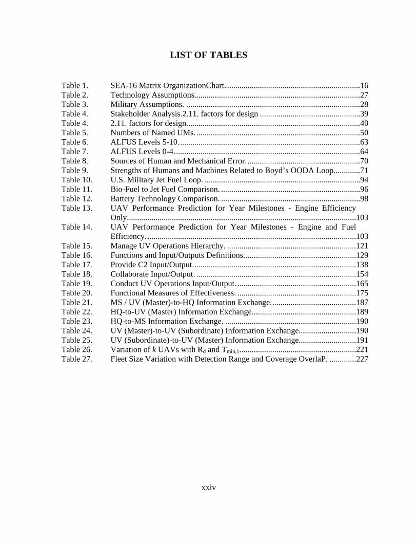
LIST OF TABLES
Table 1. SEA-16 Matrix OrganizationChart. .................................................................16 Table 2. Technology Assumptions.................................................................................27 Table 3. Military Assumptions. .....................................................................................28 Table 4. Stakeholder Analysis.2.11. factors for design .................................................39 Table 4. 2.11. factors for design.....................................................................................40 Table 5. Numbers of Named UMs. ................................................................................50 Table 6. ALFUS Levels 5-10.........................................................................................63 Table 7. ALFUS Levels 0-4...........................................................................................64 Table 8. Sources of Human and Mechanical Error........................................................70 Table 9. Strengths of Humans and Machines Related to Boyd’s OODA Loop.............71 Table 10. U.S. Military Jet Fuel Loop. ............................................................................94 Table 11. Bio-Fuel to Jet Fuel Comparison. ....................................................................96 Table 12. Battery Technology Comparison. ....................................................................98 Table 13. UAV Performance Prediction for Year Milestones - Engine Efficiency
Only................................................................................................................103 Table 14. UAV Performance Prediction for Year Milestones - Engine and Fuel
Efficiency.......................................................................................................103 Table 15. Manage UV Operations Hierarchy. ...............................................................121 Table 16. Functions and Input/Outputs Definitions.......................................................129 Table 17. Provide C2 Input/Output................................................................................138 Table 18. Collaborate Input/Output. ..............................................................................154 Table 19. Conduct UV Operations Input/Output. ..........................................................165 Table 20. Functional Measures of Effectiveness. ..........................................................175 Table 21. MS / UV (Master)-to-HQ Information Exchange..........................................187 Table 22. HQ-to-UV (Master) Information Exchange...................................................189 Table 23. HQ-to-MS Information Exchange. ................................................................190 Table 24. UV (Master)-to-UV (Subordinate) Information Exchange............................190 Table 25. UV (Subordinate)-to-UV (Master) Information Exchange............................191 Table 26. Variation of k UAVs with Rd and Tmin,1.........................................................221 Table 27. Fleet Size Variation with Detection Range and Coverage OverlaP. .............227

xxv
THIS PAGE INTENTIONALLY LEFT BLANK

xxvi
EXECUTIVE SUMMARY
Introduction
U.S. Forces will require a Command and Control (C2) Architecture enabling the
coordinated operations of manned and unmanned systems by the year 2030. The year
2030 was chosen for the scope of the project because the technology necessary for our
architecture will be available in one or two design cycles beyond our current capability.
When existing C2 structures are unable to keep up with operational requirements for
large numbers of manned and unmanned systems, a new C2 architecture capable of
meeting this requirement will be required. The purpose of this project is to develop the
concepts for a new architecture based on operational needs. We developed an
architectural concept that identifies the functional and operational aspects that will be
necessary to realize an integrated manned and unmanned conceptual architecture by the
year 2030.
Our Approach
The systems engineering approach was to:
• Differentiate the task statement of manned and unmanned systems based
on time to perform task
• Develop concepts of operations and key operational scenarios
• Perform consequence analysis
• Identify stakeholders
• Determine key design drivers/ requirements
• Identify capability gaps
• Suggest key technology focus areas
• Propose future studies to achieve our conceptual architecture

xxvii
Two missions, force protection and reconnaissance, were chosen because they are
common to all forces in their day to day operations. Focusing on these two missions
facilitated the development of the functions, operational activities, operational nodes, and
information exchanges necessary to develop the C2 architecture concept.
High Value Unit (HVU) protection is a vital function for commanders in all
military services at all levels. In 2030, HVU protection will become even more difficult
due to the advances in adversarial capabilities. For this scenario, the advantage of
utilizing unmanned aerial vehicles was modeled to extend the range of detection for a
highly capable Anti-Ship Cruise Missile (ASCM). We assume that in the year 2030 this
ASCM threat will be capable of increased speeds of Mach 4+, with reduced radar cross-
section and low flight profile.
This model depicts defense of a Carrier Battle Group (CVBG) using an extended
ring of detection provided by unmanned systems. Additionally, this model can be
applied to other joint situations, including the protection of land-based assets.
Project Organization
A matrix organization type format was used to coordinate the efforts of all team
members utilizing Integrated Project Team for specific tasking and Track Teams for
specific expertise. These organizational teams conducted a detailed analysis of the
project tasking and scoped the project into three essential deliverables:
• Produce a coherent Vision of unmanned vehicles
• Develop a Joint Systems vehicles concept
• Design a Command and Control (C2) Architecture
Following the scoping of the project a Systems Engineering Process Model was
developed in order to schedule and plan the project to completion. The process model
was composed of four phases: Project Definition, Systems Analysis, Preliminary Design,
and System Design for Utility.
xxviii
Concept of Operations
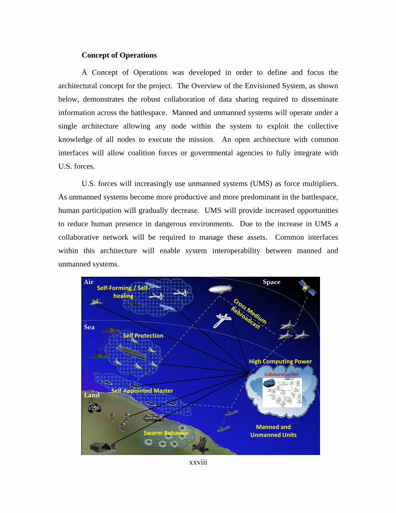
A Concept of Operations was developed in order to define and focus the
architectural concept for the project. The Overview of the Envisioned System, as shown
below, demonstrates the robust collaboration of data sharing required to disseminate
information across the battlespace. Manned and unmanned systems will operate under a
single architecture allowing any node within the system to exploit the collective
knowledge of all nodes to execute the mission. An open architecture with common
interfaces will allow coalition forces or governmental agencies to fully integrate with
U.S. forces.
U.S. forces will increasingly use unmanned systems (UMS) as force multipliers.
As unmanned systems become more productive and more predominant in the battlespace,
human participation will gradually decrease. UMS will provide increased opportunities
to reduce human presence in dangerous environments. Due to the increase in UMS a
collaborative network will be required to manage these assets. Common interfaces
within this architecture will enable system interoperability between manned and
unmanned systems.
SpaceAir
Land
Sea
Collaboration Net
INTRANET
Self Protection
Swarm Behavior
Self‐Forming / Self‐healing
Manned and Unmanned Units
High Computing Power
Self Appointed Master

xxix
Consequence Analysis
A high level risk assessment, or consequence analysis, was conducted looking at
the possible results of failing to act in establishing this architecture.
• Decrease in situational awareness due to information overload
• Reactive implementation of Unmanned Systems management
• Immature technology development causes an inability to integrate systems
• United States will fall behind technological rivals
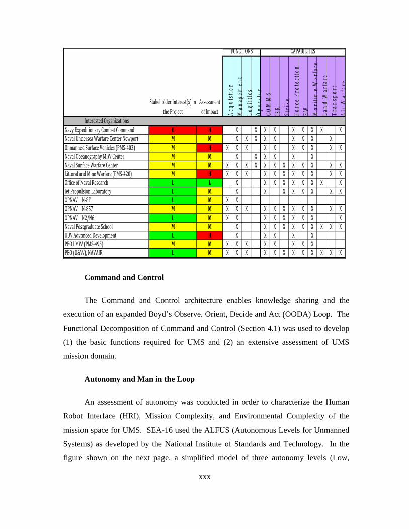
Stakeholder Analysis
Two main categories of stakeholders for this project were developed; interested
and affected organizations. Interested Organizations are those groups that have
expressed actual interest or provided input while affected organizations are those groups
that, while not expressing interest in the project, would be highly affected by the
outcome. In the table, on the following page, the “x” in the block denotes where the
organization has an interest in the function category, the capabilities category, or both.
Our first primary sponsor N8F has priorities in the acquisition function. Naval
Expeditionary Combat Command (NECC) has priorities in the capabilities category of
Communication (COMMS); Intelligence, Reconnaissance, and Surveillance (ISR); and
Force Protection.
xxx
Acqu
istio
n M
anag
emen
tLo
gist
ics
Oper
ator
COM
MS
ISR
Strike
Forc
e Pr
otec
tion
EW Mar
itim
e W
arfa
reLa
nd W
arfa
reTr
ansp
ort
AirW
arfa
re
Interested OrganizationsNavy Expeditionary Combat Command H H X X X X X X X X XNaval Undersea Warfare Center Newport M M X X X X X X X X XUnmanned Surface Vehicles (PMS‐403) M H X X X X X X X X X XNaval Oceanography MIW Center M M X X X X X XNaval Surface Warfare Center M M X X X X X X X X X X X XLittoral and Mine Warfare (PMS‐420) M H X X X X X X X X X X XOffice of Naval Research L L X X X X X X X X XJet Propulsion Laboratory L M X X X X X X X XOPNAV N‐8F L M X XOPNAV N‐857 M M X X X X X X X X X X XOPNAV N2/N6 L M X X X X X X X X XNaval Postgraduate School M M X X X X X X X X X XUUV Advanced Development L H X X X X XPEO LMW (PMS‐495) M M X X X X X X X XPEO (U&W), NAVAIR L M X X X X X X X X X X X X
Stakeholder Interest(s) in the Project
Assessment of Impact
FUNCTIONS CAPABILTIES
Command and Control
The Command and Control architecture enables knowledge sharing and the
execution of an expanded Boyd’s Observe, Orient, Decide and Act (OODA) Loop. The
Functional Decomposition of Command and Control (Section 4.1) was used to develop
(1) the basic functions required for UMS and (2) an extensive assessment of UMS
mission domain.
Autonomy and Man in the Loop
An assessment of autonomy was conducted in order to characterize the Human
Robot Interface (HRI), Mission Complexity, and Environmental Complexity of the
mission space for UMS. SEA-16 used the ALFUS (Autonomous Levels for Unmanned
Systems) as developed by the National Institute of Standards and Technology. In the
figure shown on the next page, a simplified model of three autonomy levels (Low,
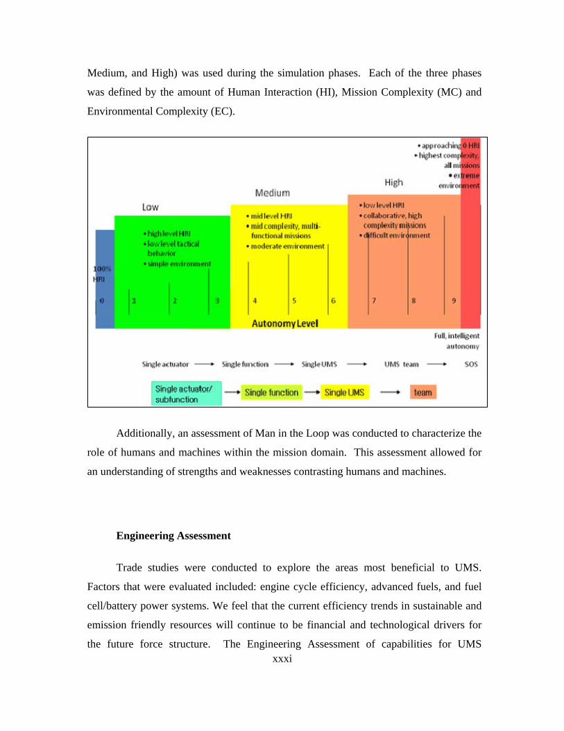
xxxi
Medium, and High) was used during the simulation phases. Each of the three phases
was defined by the amount of Human Interaction (HI), Mission Complexity (MC) and
Environmental Complexity (EC).
Additionally, an assessment of Man in the Loop was conducted to characterize the
role of humans and machines within the mission domain. This assessment allowed for
an understanding of strengths and weaknesses contrasting humans and machines.
Engineering Assessment
Trade studies were conducted to explore the areas most beneficial to UMS.
Factors that were evaluated included: engine cycle efficiency, advanced fuels, and fuel
cell/battery power systems. We feel that the current efficiency trends in sustainable and
emission friendly resources will continue to be financial and technological drivers for
the future force structure. The Engineering Assessment of capabilities for UMS
xxxii
provided the key inputs for multiple phase modeling, where application of future
technology demonstrated longer endurance for UMS on-station time.
Functional Architecture
The purpose of this architecture is to describe the integration of unmanned and
manned vehicles in all domains into a collaborative knowledge sharing environment,
allowing for unity of effort amongst all the warfare tools in the battlespace. The
functional architecture contains a hierarchical model of the functions performed by the
system, functional flow block diagrams, and diagrams showing the functional inputs and
outputs. This architecture includes the interfaces between UMS, C2 nodes, manned
operational units, and external systems. The unique aspect of this concept is that the
architecture, while focused toward unmanned vehicles, also takes into account the
integration of manned vehicles through the collaborative network. The principal
exchange of information is through a collaborative network which acts a data fusion
network that is distributed across the forces.
Modeling
We applied the architecture concepts to one of the innumerable potential
operational applications for unmanned vehicles. Our model depicted the deployment of
unmanned vehicles to provide the carrier battle group with early detection of an Anti-
Ship Cruise Missile (ASCM). This analysis began with a determination of the UAV fleet
size required to provide an ASCM early warning screen.
Some key assumptions were made for the analysis
• Benign environment
o Sea States are between 0 to 3
o No Enemy Jamming or EW countermeasures
o No UAV to UAV engagements
• ASCM RCS of 0.1 to 1 m2
xxxiii
• ACSM speed of Mach 4+
• Probability of Detection assumed to be 1
• Continuous track handling capability of a detected ASCM
• Detection to Firing Time a constant 10 seconds
• Maximum UAV patrol time approximately 45 hours
• Repair time on failure of a UAV based on triangular distribution of 4 to 8
hours, with a mode of 5 hours
• Maintenance time after mission completion based on triangular
distribution of 0.8 to 2 hours, with a mode of 1
• The cumulative total time of flight before the UAV encounters a non-
catastrophic failure is assumed to be a normal distribution of mean 200
hours and standard deviation of 60.79
• Mean Time Between Failure (MTBF) of UAVs of 200 hours
• 5% probability that the Time To Fail (TTF) will be below 100 hours of
operation
The geometric force layout was determined based on several parameters,
specifically, a surface detection range of 60km, UAV detection range of 30km, a
scanning angle of 100°, and desired continuous UAV radar coverage overlap for a Mach
4+ missile of 1-4 sec.
Modeling Phase II determined that a fleet size of 21±1 UAVs is required to
achieve the persistent early warning screen, given UAV detection range of 30km and
UAV radar coverage overlap of 1 sec. For a conservative fleet size estimate, given the
uncertainties of the coverage overlap and radar detection range, a fleet size of 35 should
be anticipated given UAV detection range of 20km and UAV radar coverage overlap of 4
sec.
Summary of Results

xxxiv
A joint C2 architecture for manned and unmanned systems based on Boyd’s
OODA Loop approach is necessary by the year 2030. Development of such architecture
will allow for large numbers of manned and unmanned nodes to operate within a single
C2 structure. Information sharing, provided by a collaborative information network that
is unbounded by physical media, mission capabilities, or geographic location, will
improve unity of effort.

xxxv
THIS PAGE INTENTIONALLY LEFT BLANK

xxxvi
ACKNOWLEDGMENTS
The SEA-16 Integrated Project Team would like to thank the faculty and staff of
the Wayne E. Meyer Institute of Systems Engineering for their commitment to our
academic development and the completion of this integrated project.
We want to thank our faculty advisor who worked tirelessly to provide guidance
and support throughout this project. Professor Gary Langford developed our
understanding of Systems Engineering principles and encouraged creative analysis of the
problem.
RADM (ret) Rick Williams and CAPT (ret) Professor Chuck Calvano provided us
a fleet perspective on the project and found multiple opportunities for us to contact
leading professionals in the development of unmanned vehicles and other defense
systems.
Each academic track of students in this project benefitted from the experience and
guidance of their faculty advisors, specifically Professor Dave Meyer, Operation
Research and Modeling & Virtual Environment Simulation Track Advisor; Professor
Peter Ateshian, Communication, Sensor & Network Track Advisor; Professor Karen
Burke, Information Assurance Track Advisor; and Professor Chris Brophy, Weapons
Track Advisor.
We would like to recognize our military advisor, CDR Douglas Burton, USN, for
his persistent interest in our academic progress and his personal efforts to ensure a
positive professional experience at NPS.

xxxvii
We wish to acknowledge the support of our NPS instructors, who provided a
tremendous educational experience that supported the concepts presented in this project.
These instructors include:
LTC Mark Stevens, USA (ret)
Professor Doyle Daughtry
COL David Matthews, USA (ret)
Professor Paul Sanchez
Professor Gregory Miller
Professor David Hart
Professor William Solitario
LTC Terry Smith, USAF
Professor James Eagle
LTC Robert Shearer, USA
Professor Matthew Boensel
Professor Edouard Kujawski
CAPT Wayne Hughes, USN (ret)
CAPT Douglas Otte, USN
CAPT Jeffrey Kline, USN (ret)
Professor Thomas Hoivik
Professor Rachel Goshorn
Professor Robert Harney
Professor Daniel Nussbaum
Professor Kristin Giammarco
We would like to thank the Associates of Temasek Defence Systems Institute
(TDSI) for their invaluable advice to the TDSI students back in Singapore. Joseph
Kasser, D.Sc. visiting associate professor in the National University of Singapore, helped
the students to examine aspects of the integrated project tasking that require further
clarifications. Mr. Lim, Horng Leong, Principal Engineer in the Singapore Defense
Science & Technology Agency shared his experience as a member of SEA-11.

xxxviii
We would also wish to thank many individuals for their contributions to the
integrated project. These include Professor Arnold Buss, for assisting in the review and
guidance on the development of the event graph and SimKit model, andProfessor Nita
Miller and LTC Anthony Tvaryanas, USAF, for sharing of their views and experience in
human factors in a complex environment and suggestion of future research.
We would like to acknowledge Ms. Barbara Berlitz and Ms. Katie Oropeza for
their tremendous administrative and technical support throughout this project.
Finally, we want to thank our families for their dedication and support through the
duration of our program and for their selfless support of the NPS and Monterey
communities.

xxxix
THIS PAGE INTENTIONALLY LEFT BLANK
1
1.0. INTRODUCTION
1.1 PROJECT BACKGROUND
Changing tactics and missions of the battlefields has challenged the
Command and Control (C2) of combat throughout the history of warfare. In the
battlefields of the past, the commander relied on message runners and voice
commands. Messages could take weeks to months to cross a continent or ocean.
Technology supports the modern battlefield commander by providing global
reach with command only a few seconds delay. Today’s commander can
exercise command and control, albeit fundamentally, it is the modern application
of the C2 of yesterday which he must use to determine a course of action. The
commander must overcome the ambiguity during military operations to analyze a
situation, make a decision, and direct forces. Given a parity of resources and
capabilities, the commander that makes and carries out a correct decision before
his adversary will be at an advantage.
“We need for unmanned aircraft to act like manned aircraft.
We need unmanned aircraft to be tasked like manned aircraft.
We should be capable of flying both manned and unmanned
platforms together, to include multiple unmanned airframes
controlled by one operator,” the general continued. “And we
need commanders to have the confidence that unmanned or
manned, it doesn't make a difference, as they are equally
effective,”1
-Gen. William T. Hobbins, USAF (2006)
The primary task of this integrated project is to design an overarching C2
architecture concept for manned and unmanned vehicles operating in a 2030
battlespace. Systems Engineering and Analysis Cohort 16 (SEA-16) is not
1 “Unmanned Aircraft Key to Future Operations, General Says” American Forces Press
Service http://www.defense.gov/News/NewsArticle.aspx?id=1730, accessed 17 May 2010.
2
attempting to redefine C2; rather application of proven C2 fundamentals is
necessary to develop an architecture which integrates manned and unmanned
vehicles in the air, land, sea, undersea, space domains. The C2 cycle used in the
development of our concept is Boyd’s OODA Loop (Observe, Orient, Decide,
and Act), as further decomposed in Section 3.1.
We successfully showed in this project that a future Command and
Control architecture can integrate the many elements of the strategic, operational,
and tactical elements of the U.S. and Coalition partners. Regardless of the
platform or tool that is executing the commander’s orders, we showed a C2
architecture that allows for quality decisions to be executed inside the
adversary’s decision making cycle.
1.2. FUTURE STAKEHOLDERS
Advances in missile technology have Anti-Ship Cruise Missiles (ASCM)
speeds increasing towards the Mach 6+ threshold. The application of this
technology necessitates the application of all available technology to counter
these high speed threats. Therefore, the main consequence of not instituting the
architecture developed in this project is that defensive measures for High Value
Units (HVU) (aircraft carriers, strategic buildings, command posts, etc) utilizing
current defensive systems, weapons, and tactics will be limited to one, or maybe
no reactive launches.
This limitation of defensive measures was a fundamental consideration in
the stakeholder analysis conducted in this project. The highest level stakeholders
detailed in Section 2.10. are those organizations that have the long-term vision
essential in order to implement the proposed architecture within this project.
1.3. PROJECT TASKING
1.3.1. Systems Engineering and Analysis (SEA) Tasking Statement
The tasking statement designated in SEA-16 Capstone Project Objectives
Memorandum stated:

3
“Develop a Joint Systems concept and supporting architecture that
supports the integration and utilization of Unmanned Vehicles into
the Navy Fleet Structure, focused on NECC [Naval Expeditionary
Combat Command] missions. Consider current and evolving
unmanned technologies to develop a complete architecture that is
flexible to emerging unmanned technologies. Design a C2
[Command and Control] architecture with a possible common
control system. Reassess the current utilization of manned and
unmanned vehicles in seeking a reduction in architectural
complexity, and determine alternative uses of those resources.
Considering potential technology gaps, determine a more
streamlined architecture with gap fillers. Focus on the
development of a system of systems and family of systems in
support of the NECC enterprise. Consider focused mission areas
per platform to concentrate mission tasking, promote specialization
of manning, and shrink force structure. Iterate the task nature, as
approved by your primary faculty advisor, Prof. Langford.
Produce a coherent vision of unmanned vehicles in support of
NECC tasks and identify the requirements for supporting or
collaborating forces.”2
2 SEA-16 CAPSTONE PROJECT OBJECTIVES, 03 September 2009

4
1.4. SCOPING
The SEA-16 Integrated Project Team scoped this problem by
decomposing the Tasking Statement and building on those with key
considerations. These concepts were mapped to the three key deliverable items
for the overall project. These deliverables are:
• Produce a coherent vision of unmanned vehicles • Develop a Joint Systems vehicles concept • Design a Command and Control (C2) Architecture
Figure 1 displays a graphic representation denoting the key
considerations with respect to the three identified deliverables (shown in gold
bubbles) for this project. Arrows indicate inputs to the deliverables: Vision,
Concept, and Architecture.
1.4.1. Tasking Interpretation
1.4.1.1. Tasking Statement Decomposition
Concepts that were extracted from the tasking statement, as
shown in black in Figure 1, are outlined below.
Requirement for Coalition Operations The use of coalition
partners will be more important in 2030 than it is today. Enhanced
interoperability with coalition partners will be possible with an overarching
architecture that can be used by both the United States and its allies.
Command and Control Command and Control of all
systems in the fleet should be managed under a single architecture. The
limitations of the currnet system inhibits the commander due to the time taken to
interpret inputs from separate systems into a coherent evaluation of the situation.
Development of an overarching architecture will allow for the streamlining of
information inputs and decrease the time for decision making. This could
increase commander’s situational awareness, allowing them to make more

5
informed decisions and allow users access to information in order to take proper
action.
Reduce Complexity To enhance the situational analysis of the
battlespace, there must be an increase in processed data provided to the user.
This processed data is essential to the efficient planning of combat operations.
Additionally, an overarching architecture would reduce complexity by
decreasing the information transfer lag produced by the cross connection of
multiple incompatible systems.
Integration and Utilization of UMS in the Navy Fleet Structure
The fleet and force structure of the future will be a combination of manned and
unmanned systems. Regardless of the platform providing the information, any
operator (manned or unmanned) should have access to all data in order to
optimize support to combat operations.
Utilization of UMS (Current Vs Future) The current utilization
of UMS must be examined in order to project the potential future mission space.
This information will provide an understanding of missions, capabilities, and
technological needs to develop the architecture to support these needs.
Additionally, future technology, the roles of manned and unmanned systems, and
the required levels of autonomy must be understood.
Current Technical Gaps and Potentials Current technology
must be evaluated to identify the currnet gaps that exist in the systems. These
gaps can be addressed with potential technology and continued research, in order
to design a system that meet the capability needs of the future.
Reduction of Force Structure The use of UMS in the
future could aid in reducing the number of personnel on the battlefield. This in
one area where time was not committed for further study, but for any future
system the cost and number of personnel compared to UMS would need to be
evaluated.
6
1.4.1.2. Project Team Interpretation
Additional concepts identified by the team were items not
included in the project tasking statement, but that needed to be addressed in this
project. These additional items are shown in red in Figure 1, and outlined below.
Raise, Train and Sustain Authority In the 2030 timeframe, this
system must not only be technically realized, but the force must be ready to
operate the system as well. Considerations must be made to train users and
maintainers to apply this system and maximize its usability.
External Stakeholders An understanding of the system
needs requires an examination of stakeholders. These include the function they
play in the system as well as the mission capabilies they require. The external
stakeholders provide input and receive output from the system. A discussion of
the process and results of the needs is shown in Section 2.10. of this report.
Ideal UMS Fleet Structure UMS will be required to operate
within the manned fleet structure, and enhance the functional capacity of the
force. The relationships between varying nodes within the system must be
studied in order to fill the capabilities needed.
Pros and Cons of UMS There are many implications that
are tied to the use of UMS. The concept must recognize the strengths and
weaknesses of these systems with consideration to the strengths and weaknesses
of manned systems.
What problems are solved by UMS? What value is derived from
using unmanned vehicles versus manned vehicles? To answer this question, the
group assessed societal views on the value of human life, the cost of training a
person versus maintaining a machine, and the ease of replacing a machine versus
a human. Additionally, the missions were broken down to their essential tasks in
order to identify task that are more effectively completed though the use of
UMS.
7
Mission and Roles (with Assumptions) On what missions
does it make sense to utilize unmanned systems? The group had to make
assumptions based on the potential missions and uses of UMS in the year 2030.
The group analyzed missions that could be enhanced through the use of UMS.
The group also looked the different facets of those missions and determined what
roles UMS would play.
Vertical and Horizontal Linkages This area of study focused
on the interactions between nodes in the battlespace. The horizontal linkages are
interactions between nodes with similar functions, such as C2 node to C2 node or
between UV and UV. The vertical linkages are the interactions between nodes
with different functions, such as the C2 node to the operational vehicles. These
linkages are valuable because they give insight to the type of information that
will need to be shared.
Manned and Unmanned This area of study involved research
as to how manned and unmanned forces will need to interact in the
accomplishment of future missions. A determination must be made as to
whether manned and unmanned forces require separate C2 architectures or
should their system’s C2 architectures be integrated? To address this issue the
group assessed the different roles each manned and unmanned forces would have
during the anticipated missions of 2030.

8
Figure 1. Broad Deliverables & Key Principle Considerations

9
1.4.2. Project Limitations
Unmanned Systems (UMS) design cycles influenced the
timeframe for the project. For the implementation of our concept technology
must mature through 2-3 design cycles. This would enable the joint system to be
obtainable by the year 2030.
This project focused on U.S. manned and unmanned weapons systems,
but acknowledges that collaboration with coalition forces will require analysis of
foreign systems as well.
The material in this report is not intended to recommend changes to the
organizational layout of the Department of Defense, or imply any specific unit’s
chain of command relationship.
Inclusion of any development item or current platform in this report does
not imply endorsement for acquisition of that specific system.
Personnel allocation will be considered in general terms, and no specific
personnel requirements will be determined.
A brief survey was conducted to examine the legal issues associated with
the general operation of UMS. These topics were limited to: International Laws,
Law of Armed Conflict, United Nations’ Convention on the Laws of the Sea
(UNCLOS), International Civil Aviation Organization (ICAO), National
Sovereignty, and Issues within the United States. These topics were addressed
due to their direct correlation to the operation of UMS. Additionally, this report
does not attempt to determine who is legally responsible for actions conducted
by autonomous vehicles.
A full cost analysis of the system would be required in a future study of
this proposed concept.
This project did not include a cost estimate for a fully autonomous
system. Much of the technology is still theoretical and the physical composition
and bounds of the enabling system are not described in specific terms. There are

10
two specific cost consideration categories: human costs (including training,
human system integration, and salary and entitlements) and machine costs (lines
of code, software maintenance, software upgrades, and other costs).
Analysis was not conducted on specifics concerning air space
management, water space management, or frequency management.
1.5. SYSTEMS ENGINEERING PROCESS
1.5.1. Development of Systems Engineering Process Model
Initially, the Systems Engineering (SE) Track Team Members developed
a list of tasks required to formally develop a systems engineering process.
Below is a list of the main tasks required:
• Problem Definition • Factors for Design • Trend Analysis • Development of Assumptions for both Military and Technology • Needs Analysis • Review of Current C2 process regarding unmanned systems. • Develop a Conceptual C2 Process for the year 2030 • Capabilities Analysis • Gap Analysis • Stakeholder Analysis • Risk Assessment • Development of Scenarios • Decomposition of Command and Control • Functional Decomposition • Methods of Analysis • Develop Modeling/ Simulation
1.5.2. Systems Engineering “Vee” Process
The “Vee” model is a widely recognized Systems Engineering process.
The “Vee” model, shown in Figure 2, was developed to address issues
concerning the decomposition, definition, integration, and verification of a
11
system.3 Mooz and Forsberg describe what they call “the technical aspect of the
project cycle” by the “Vee” process model.4
The model begins with the definition of system requirements on the
upper left as the problem is decomposed and defined. This phase of the model is
meant to resolve the system architecture, preparing the details that will be
essential to system design. First, the system requirements are defined primarily
based on stakeholder needs and the functions for which the system will be
designed to perform. These requirements are meant to clarify the functions to be
performed by the system. The functions are allocated to subsystems. The system
is comprised of subsystems. The systems engineer matches functional
requirements to subsystems, allowing for specific components to be chosen that
will perform the required functions at the component level. Once this level of
design is completed, the system design is then “built upwards” to begin to
produce a user-validated system on the upper right of the Vee Model.
Verification of components and systems with respect to the originating
requirements occur through each level of the integration and verification
sequence. After verification and validation, the system becomes fully
operational.
3 Mooz , Hal and Kevin Forsberg. The Dual Vee – Illuminating the Management of
Complexity. Paper submitted to the Sixteenth Annual International Symposium of the International Council
4 Blanchard, Benjamin S. and Wolter, J Fabrycky, Systems Engineering and Analysis, 4th Edition, Pearson Prentice Hall, Upper Saddle River, NJ, 2006.

12
Figure 2. Systems Engineering “Vee” Model5
The “Vee” Model provided a basis to begin developing our process
model of the project. It became apparent early on that the “Vee” Model was not
the logical choice for our process due to many functions that would not be
considered or analyzed. One example is the last phase when the system is tested
and validated. Our project focused on analysis of a future concept, and specific
subsystems were not designed of tested.
Additionally, the “Vee” Model includes many processes that are not
required for this project, several aspects of this model which are not applicable,
and multiple tasks are not detailed to the level needed in order to develop a
system architectural concept.
1.5.3. SEA-16 Project Tailored Process
SEA-16 developed a tailored process based on a modified “Vee” Model,
shown in Figure 3. Our modified model is composed of four phases. These
5 Ibid.

13
phases are: Project Definition, Systems Analysis, Preliminary Design, and
System Design for Utility.
This model provided the framework for the development of the
architecture concepts and allowed the team to decompose and refine the project
as work progressed from “Project Definition” through “System Design for
Utility”.
Work in each phase of the project builds upon itself as the basis for each
follow-on phase. Additionally, a feedback loop provides the capability to review
work completed in previous phases. This feedback loop recognizes the need for
multiple iterations required for development.
1.5.3.1. Project Definition Phase
In the Project Definition phase, the problem was decomposed through
several tasks. A formal vision statement was developed to provide
direction for the study. This vision statement is contained in Section 2.1.
A stakeholder analysis was conducted which identified and analyzed each
stakeholder’s functional role and capability mission area. The functional
requirements are the role they play in relation to the system and the
capability requirements relate to mission areas of the system. The results
of the stakeholder analysis are detailed further in Section 2.10. and shown
in Table 4. The results of the needs analysis are contained in Section 2.3.
During this phase, the team also completed a Consequence Analysis to
identify trends and issues pertaining to the implementation of the
architecture. These results are contained in Sections 2.4 and 2.5.
Command and Control, Technological, Geopolitical, and Military factors
for design were listed to guide the context of the project.
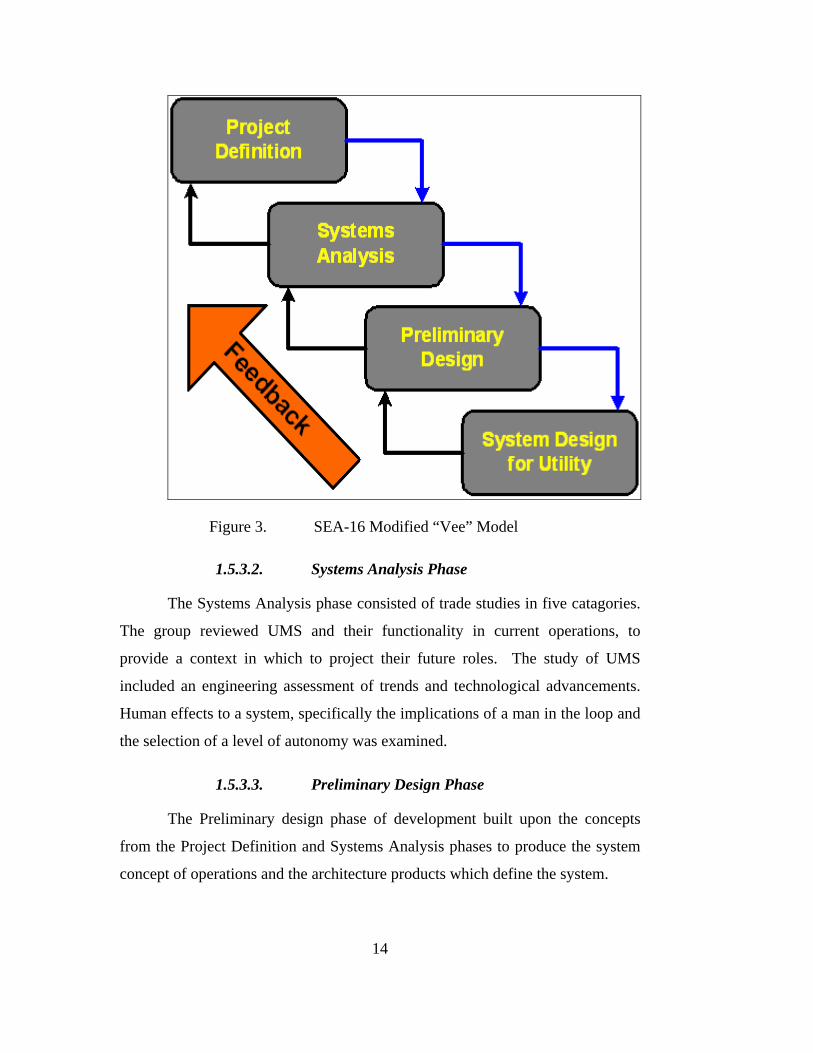
14
Figure 3. SEA-16 Modified “Vee” Model
1.5.3.2. Systems Analysis Phase
The Systems Analysis phase consisted of trade studies in five catagories.
The group reviewed UMS and their functionality in current operations, to
provide a context in which to project their future roles. The study of UMS
included an engineering assessment of trends and technological advancements.
Human effects to a system, specifically the implications of a man in the loop and
the selection of a level of autonomy was examined.
1.5.3.3. Preliminary Design Phase
The Preliminary design phase of development built upon the concepts
from the Project Definition and Systems Analysis phases to produce the system
concept of operations and the architecture products which define the system.

15
1.5.3.4. Systems Design for Utility Phase
The System Design for Utility phase applied the system concepts to
model system application. In this project, the model demonstrates one of the
countless possible applications of the system.
1.6. TEAM ORGANIZATION, ROLES, RESPONSIBILITY
1.6.1. Team Composition
Each team member was assigned to specific Integrated Project Team
(IPT), which are standing groups ready to receive project tasking, as illustrated in
Section 1.6.2, and to a specialty area Track Team, as illustrated in Section 1.6.3.
Team members in each specific discipline area were selected for an IPT to ensure
cross-disciplinary inputs and interaction. This organizational concept promoted
efficient exchanges of information, reduced redundant efforts, and promoted
lively discussions. Detailed work within a specific discipline area was
completed by the Track Teams. Work within the Track Teams focused on the
subject matter of their curriculum.
The SEA-16 organization is shown in Table 1. LT Thompson was
selected as the Project Manager and had overall responsibility for successful
completion. MAJ Ang Teo Hong (Republic of Singaporean Air Force) was
elected Assistant Project Manager.
During the fall quarter 2010, the students in Monterey began to work
with the Singaporean-based students. Following the Systems Engineering
process lecture, which was conducted by Professor Gary Langford in October
2009 with students from NPS and the National University of Singapore (NUS)
though a Video Teleconference (VTC), the Temasek Defence Systems Institute
(TDSI) students set up the Singapore SEA-16 Organizing Committee (SSOC) to
spearhead all initial project discussions and clarifications between the two
geographically separated groups of students. The members of the SSOC were
MAJ Ang Teo Hong, MAJ Lim Han Wei, MAJ Gabriel Tham Chi Mun, Yinon

16
Costica, LT Dustin Cunningham, Mr. Wong Ka-Yoon and Mr. Delvin Gho Seng
Wee.
Project Manager
Asst. Project Manager
IPT1 IPT2 IPT3 IPT4
Systems Engineering LT Johnson LT Nilsson LT Moran CDR Quincy
MAJ Ting Chi Yon Delvin Gho Wong Ka‐Yoon Yinon Costica Tommy Chia LT Adam Matthews Jason Wong
MAJ Lim Han Wei ME5 Ng Wei Gee Tan Yean Wee ME5 Tong Kee Leong Lu Chin Leong Chia Boon Chye Henry Seet ME5 Lo Chee Hun
ME5 Gabriel ThamHo Liang Yoong Raymond Quah Quek Chee Luan Ang Kah Kin
Toh Boon Pin Ng Yeow ChengCPT Tan Wei Chieh ME4 Tan Chin Wah John LT Dion G Fontenot LT Omari D Buckley
LT Dustin Cunningham CPT Lim Wei Han Eugene
Lead
ersh
ip LT Bradley Thompson
MAJ Ang Teo Hong
Trac
ks
Simulation Team
Comms, Networks, and Sensors
Information Assurance
Weapons
TABLE 1. SEA-16 MATRIX ORGANIZATIONCHART.
1.6.2. Integrated Project Teams
Four members of SEA-16 were assigned to lead an IPT. LT Johnson led
IPT 1, LT Nilsson led IPT 2, LT Moran led IPT 3, and CDR Quincy led IPT 4.
1.6.2.1. Integrated Project Team 1
IPT1 focused on current mission capabilities and gaps for the
Explosive Ordnance Disposal (EOD) mission area of NECC. This was done
with a question and answer session with actual EOD personnel. From the
information gathered an analysis of potential future uses of UMS throughout the
EOD spectrum was performed. From that analysis three scenarios were
developed to explain the mission, gaps and possible solutions for UMS in EOD.
These mission gaps were then presented to the Steering Committee in order to
explore possible follow on studies and agree upon the ultimate area of focus.
17
1.6.2.2. Integrated Project Team 2
IPT2 initially conducted research regarding NECC’s Riverine
forces. The team researched the chain of command, manning, equipment, and
mission requirements. The team then analyzed the operating environment to
identify threats, environmental and terrain aspects, and common scenarios faced
by Riverine operators. The team identified potential uses of unmanned vehicles
in order to enhance operational effectiveness.
IPT2’s next major focus area was the development of the
functional architecture. The team developed a functional decomposition,
functional flow block diagrams, input/output diagrams, and performance
characteristics for each function.
1.6.2.3. Integrated Project Team 3
IPT3 completed work in several key areas. First, the group
examined the missions and roles of the Maritime Expeditionary Security Force
(MESF) component of NECC. These missions were detailed in a hierarchical
fashion according to functional breakdowns. The highest-level function was
“Conduct Force Protection”. As the project evolved, the team focused on the
implications of having a man-in-the-loop for a system. This trade study involved
identified human and machine roles, and considered the information in terms of
the command and control paradigm.
1.6.2.4. Integrated Project Team 4
Initially, IPT4 developed a plan for the project. The team
conducted a tradeoff of three Systems Engineering process models (i.e.,
waterfall, spiral, Vee), to compare the time and documentation requirements.
This analysis led to the Systems Engineering Waterfall Process developed by the
Systems Engineering team. IPT4 researched and selected a definition for
autonomy and autonomous. IPT4 also selected the Autonomy Levels for

18
Unmanned Systems (ALFUS) model that would be used by the teams. This
evaluation is further described in Section 3.3.
1.6.3. Track Teams
As with the IPTs, members of the team were also assigned to a Track
Team. The purpose of the Track Teams was to focus the knowledge of the group
on the specialties associated with their curriculum. There were five Track Teams
involved in the project; the Systems Engineering Track Team led by CDR Keith
Quincy, the Simulations Track Team led by Wong Ka-Yoon, the
Communications, Network, and Sensors Track Team lead by MAJ Tong Kee
Leong, the IA Track Team lead by Toh Boon Pin, and the Weapons Track Team
lead by LTJG Dustin Cunningham.
1.6.3.1. Systems Engineering Track Team
The Systems Engineering (SE) Track Team was responsible for
the overall coordination of the project. This team provided the overall direction
for the project by developing the Waterfall model which was used to manage the
processes for the project. They provided the knowledge and guidance to scope
and iterate the project. Team members attended conferences, lectures, and
corresponded with stakeholders. Due to scoping, not all aspects of the concept
would be examined, and these decisions were determined by the SE Track Team.
A listing of items that would require future research and study to aid in realizing
the system concept proposed is included in Section 6.3. of this report.
1.6.3.2. Simulation Track Team
The Simulations Track, comprised of students from the
Operations Research (OR) and Modeling, Virtual Environments, and Simulation
Institute (MOVES) curriculum provided perspective on the problem formulation
and scenario selection by comparing current operational practice with proposed
future operations. The team members played a role in defining the scenario for
demonstration of the C2 architecture proposed in this report. An analytical-

19
stochastic model, augmented with discrete event simulation, was built to
illustrate the notional force size and force effectiveness of a fleet of unmanned
aerial systems in detecting an incoming ASCM. A sensitivity analysis was
conducted. These results, further detailed in Section 5.7., showed that for this
concept between 21 and 35 UAVs would be required to extend the ISR and
subsequent Force Protection ring around a HVU. Through both the process and
results of the modeling and simulation, greater clarity was achieved concerning
the future C2 architecture, component systems and Concept of Operations
(CONOPS).
1.6.3.3. Communications, Networks, and Sensors Track Team
The Communications, Sensors, and Networks Track Team
provided the expertise in communications and surveillance to the various in IPT
during the initial stages of the project. After the shift in focus for the project, the
team provided critical support the Command and Control Architecture Task
Force (C2ATF) and Operations Research and MOVES Task Force (OMTF).
Specifically, the sensors group provided the geopolitical trends and operational
imperatives that shaped the way the sensors technology may evolve. The team
also explored and highlighted possible technologies that supported the Command
and Control (C2) architecture. The team also focused on the C2 architecture
development. Additionally, the sensors team contributed to the development,
simulation and validation of the C2 architecture by evaluating and proposing an
appropriate sensor detection range for a sea-skimming missile operating at
supersonic speed. An evaluation report was submitted for both C2ATF and
OMTF.
The Communications and Network (CN) systems facilitate
dissemination of information over vast Area of Operation (AO) in a timely and
organized manner. These mechanisms would form the backbone for Command,
Control, Communications, Computers and Intelligence (C4I) architecture and
enable joint Command, Control, Communications, Computers and Intelligence

20
Surveillance and Reconnaissance (C4ISR) operations. In this integrated project,
the CN team provided expertise to the C2ATF in developing the Command and
Control architecture for air, land and sea operational theatre, established the
generic type of traffic profile between sensors, command and shooters in the
OODA loop. The CN team also supported OMTF in analyzing communications
link budget and assessed the viability of the communications network in the
proposed scenario.
1.6.3.4. Information Assurance Track Team
The Information Assurance (IA) group was involved in the design
of Command & Control (C2) architecture capable of supporting different type of
operations involving manned and unmanned vehicles in 2030. The team
members worked closely with other groups to ensure a coherent C2 architecture
that is capable of supporting the various initiatives. The IA group also identified
ways to safeguard information assets by examining problems from an
information assurance perspective. The confidentiality; integrity and timely
availability of information often play an important part in the success of military
operations. This included
assessment of security for individual components that formed the
C2 architecture to ensure information flow among these components.
Appropriate security measures (such as access control, authentication protocol,
implementation of cryptography) were proposed taking into consideration the
constraints imposed by the operational environment. Potential risks were
identified to help support proper risk management decision making.
1.6.3.5. Weapons Track Team
The Weapons Systems Track provided the technical view-point
for the SEA-16 design project by implementing the study of Mechanical and
Astronautical Engineering. The students in this track provided identification of
technical problems and helped solve platform specific issues in terms of future
performances and data extrapolation. Weapons Systems students researched and
21
analyzed current unmanned platforms to understand what these systems will be
capable of over the next two decades. Additionally, during focused trade studies
of propulsion-based technology, the knowledge of design, testing, maintenance,
failure prediction, and operation requirements for the technologically advanced
military equipment of the future allowed for platform performance predictions
that were integrated into the models and simulations. The Weapons Systems
Track also worked in cooperation with the CNS Track team on areas that
involved the application of sensor-shooter OODA loops. The ability to bridge the
gap between engineering technology and military operations, in addition to
presenting mathematically and technically diverse material, made the Weapons
Systems Track and integral part of the SEA-16 design project.

22
THIS PAGE INTENTIONALLY LEFT BLANK

23
2.0. CONCEPT OF OPERATIONS (CONOPS)
2.1. PROJECT DESCRIPTION
The military domain of 2030 was viewed as being both local and global, which
meant that information gathered at a specific location must be able to be disseminated to
enrich the situational awareness of forces regardless of where operational nodes are in
relation to the information gatherers. The C2 architecture needs to be flexible to allow
new technology to be integrated into the C2 framework. The overarching C2 architecture
will provide the structure to drive the integration of technological advances into the
existing system. Without an overarching C2 structure, the US and coalition forces may
not be able to exploit technological advances as well as it could with an adequate
architecture.
2.2. BACKGROUND
There is no overarching command and control architecture that integrates manned
and unmanned vehicles within the battlespace. Some problems with the current system
include:
• Direct communication occurs only directly between specific users and
vehicles, or directly between users (Shown in Figure 4)
• Situational awareness is not maximized due to communications and
data sharing limitations
• It is difficult for users to provide cross mission utilization of platform
• Fusion of information occurs by the collaboration of users directly
with each other
• Overall, forces are a mix of individual systems and micro-level
systems of systems
There exists a need to fulfill an enhanced Command and Control Capability
that:

24
• Provides a Common Battlespace picture to all users
• Includes a Common interface needed to enable system integration
Figure 4. Characterization of Current Command and Control Relationships
2.3. TRENDS AND ASSUMPTIONS
2.3.1. Technology Trends
SEA-16 conducted a trade-study to determine trends in technology that
may have key impacts on the C2 architecture required for future battlespace coordination
and tasking.
Common Communication Architecture In recent years the U.S. Navy
has battled a costly maintenance, logistics and support problem. Much of the trouble lies
with the fact that many of the C4I systems aboard Navy ships requires a separate network
infrastructure with a unique set of connections maintenance and repair experts to keep the
system running. Experts believe that migrating to a single Common Communication
Architecture reduce the expense of networks while the abilities continue to expand.6
Composable Systems Composable systems that allow different
systems to collaborate and enhance multiple capabilities will be prevalant in the future.
6 Hoover, Nicholas J., “Army CIO Advances Consolidation Effort,” Information Week, December 29, 2009 http://www.informationweek.com/news/government/leadership/showArticle.jhtml?articleID=222002965

25
With the increase in functionalities per product, unmanned vehicles and soldiers can
achieve higher levels of autonomy.7
Nanotechnology Nanotechnology is the study of the controlling
matter on an atomic and molecular scale. This technology generally deals with materials
of the size 100 nanometers or smaller.
Nanotechnology is very diverse, ranging from extensions of conventional
device physics to completely new approaches based upon molecular self-assembly, from
developing new materials with dimensions on the nano-scale to investigating whether it
can directly control matter on the atomic scale.
The implications of nanotechnology ranges from medical and
environmental, to fields such as engineering, biology, chemistry, computing, materials
science and communications. Specific to implications to military C2 functions,
Potentially, nanotechnology is a key driver to increase memory space and processing
power, miniaturization of electronic devices and improving energy efficiency.8
Improvement in Energy Efficiency Synthetic Fuels, lithium ion
batteries and fuel cells are examples of improvement in energy density over the recent
years. This increase in density will no doubt directly affect the endurance of Unmanned
Vehicles. With a higher endurance, operational time will increase and thereby giving rise
to an increased radius of operation.
Automation Assuming technology advancement continue to make
moderate gains, the ability for machines to conduct more and more routine operations
will allow for the reduction of man power. An example of this can be found in the
Navy’s new Littoral Combat Ship (LCS).9 Increases in automation allow for machines to
do more of the work that humans currently perform, and reduce operator interaction.
7 Hoffman, Michael, “ Technology by 2030: Looking to Change Game,” Air Force Times, January 20,
2010, http://www.airforcetimes.com/news/2010/01/airforce_scientist_011810w/ 8 American Elements “Nanotechnology Information Center,”
http://www.americanelements.com/nanotech.htm, accessed May 15, 2010. 9 Access my Library “General Dynamics Robotic Systems Awarded Navy LCS Automated Contrac”.
July 21, 2008, http://www.accessmylibrary.com/coms2/summary_0286-34837787_ITM

26
Micro Air Vehicle Micro Air Vehicle (MAV) refers to a class of
unmanned air vehicle (UAV) that is restricted by size. According to the definition
employed in Defense Advanced Research Projects Agency’s (DARPA) program, the
limits on MAVs are those crafts that are less than 15 cm (about 6 inches) in length, width
or height. MAVs are at least an order of magnitude smaller than any conventional UAVs
currently operational use.10
Taking inspiration from flying insects and birds to achieve unprecedented
flight capabilities has fast become a new trend in the MAV community. Other than
unsteady aerodynamics of using flapping wings, aspect that further inspired the engineers
includes; distributed sensing and acting, sensor fusion and information processing.
MAVs are envisioned to be an affordable system that will be locally
owned and operated at the platoon level or below. With the reduction of latency and size
inherent in current assets, MAVs will be capable of operating in constrained
environments like urban canyons and ultimately the interior of buildings. Consequently,
individual soldiers will receive on-demand information about the surroundings, resulting
in unprecedented situational awareness, greater effectiveness and fewer casualties.
MAVs are predicted to undergo a rapid evolution in military usefulness in the near
future.11
10 McMichael, James M.,“Micro Air Vehicles – Towards A New Dimension in Flight,” Federation of
American Scientists, August 7, 1997, http://www.fas.org/irp/program/collect/docs/mav_auvsi.htm 11 Hanlon, Mike, “UAVs Get Smaller: The Micro Air Vehicle Nears Readiness,” Giz Magazine,
September 25, 2005, http://www.gizmag.com/go/4779/

27
2.3.2. Assumptions
Technology assumptions and military assumptions were made to
determine possible implications for 2030 operations. Six key assumptions in the
categories of technology and military were identified. These results can be found in
Table 2 and Table 3.
Technological Assumptions There will be reduced proliferation of
proprietary technology, making system interfaces highly compatible and reducing the
costs required to modify a product for compatibility. Systems will have increased
functionality, with multiple mission capabilities. To complete multiple missions at once,
systems will require high levels of autonomy because humans will be unable to maintain
the required operational tempo. As unmanned systems become more productive, human
participation could decrease. This will increase the general reliance on unmanned
technology, requiring the implementation of a collaborative C2 architecture to manage
these assets. Energy efficiency will increase, enhancing mission capability by increasing
on-station time for all vehicles. Lastly, the possible lower costs of entry into this
technology will make it available to many state and non-state actors throughout the
world. This will make maintaining cutting edge technology critical to counter these
continually evolving threats.
Assumption Implication
Moving from proprietary architecture to a common architecture
High R&D costs to mature common UMS C2 architecture
Increased individual system functionality and mission capabilities
Higher level of autonomy for unmanned vehicles
Unmanned systems with increased autonomy will become highly productive
Increased productivity of highly autonomous systems will reduce necessity for human participation
Increased reliance on unmanned technology Collaborative integrated C2 architecture will be necessary to manage large quantities of vehicles
Increased use of efficient energy sources Increased on-station time for unmanned vehicles
Smaller technology gap on a global scale Critical to investment in advanced technology
TABLE 2. TECHNOLOGY ASSUMPTIONS.

28
Military Assumptions The first assumption in 2030 is U.S. forces
will have a near-peer competitor, necessitating the use of UMS as force multipliers. In
addition to our own forces, coalition forces will be needed to counter common threats to
maintain global security. To enable their participation, common interfaces will be needed
to ensure full collaboration and the maximum availability of assets. The increased
military reliance on technology will drive the need for a technologically savvy force. The
desire to protect human life continues to increase, and unmanned vehicles will continue
to provide opportunities to reduce human presence in dangerous environments. Our
forces will need to be able to react quickly to conflicts around the world, possibly
requiring more expeditionary forces to be forward based. Finally, all forces will be
fighting for the use of the RF spectrum. This will necessitate maintaining spectrum
dominance and optimization of available space.
Assumption Implication
U.S. forces will have a near-peer competitor Affects all current planning norms and assumptions, including need for UMS as a force multiplier
Greater use of coalition forces Increased need for common interfaces
Increase in military reliance on technology Higher need for technologically trained force
Protection of military personnel will be paramount Removal of humans from dangerous environments will necessitate increased unmanned presence.
Reliance on mobile global force Expeditionary “ad-hoc” forward basing becomes more common
Contention of finite RF spectrum usage between all forces (Friends and Foes)
Need for spectrum dominance and optimization strategy
TABLE 3. MILITARY ASSUMPTIONS.

29
2.4. OVERVIEW OF THE ENVISIONED SYSTEM
2.4.1. Overview
Figure 5. Overview of the 2030 Joint Command and Control Architecture Concept
The 2030 Joint Command and Control Architecture, as shown in Figure 5.,
will enable a robust collaboration of information across all warfare domains to
disseminate information in order to enhance situational awareness within the battlespace.
This allowed any node within the system to exploit the collective knowledge to execute
its mission. Advanced collaboration will be enabled by advances in information sharing,
specifically a Collaboration Network with High Computing Power, compatible
communications standards, and an Advanced Cross Medium Rebroadcast capability. An
open architecture design allowed for coalition forces or government agencies to interface
with the system, and fully integrate with U.S. forces.

30
2.4.2. System Scope
The system will be composed of all nodes and their interfaces that
operate in the battlespace and are under the authority and responsibility of U.S. military
forces, or operating in cooperation with those forces. Each of these acts as either an
input, output, or both with respect to the system.
Nodes include, but are not limited to:
• Manned Vehicles
• Unmanned Vehicles
• Personnel
• Broadcasting and Rebroadcasting Stations
• Satellites
• Computer Networks
• Command Centers
2.5. GLOSSARY
See Section 7.0. for a complete listing of all abbreviations, acronyms, and
definitions used in the compilation of this project.
2.6. DOCUMENT REFERENCES
See Section 8.0. for a listing of sources that were referenced multiple times.
Footnotes are used throughout the paper to properly document sources.

31
2.7. GOALS, OBJECTIVES AND RATIONALE FOR THE NEW SYSTEM
2.7.1. Goals and Objectives of the New Capability
The goals and objectives of the system are summarized in Figure 6.
Figure 6. Goals and Objectives of the System
Enhance Force Capabilities. This architecture concept must enhance force
capabilities on higher command levels, by providing commanders and planners with
improved awareness of the entire battlespace through improvements in ISR. By utilizing
more timely and complete information, commanders will have the opportunity to have a
shortened OODA Loop. Additionally, an open architecture design ensured coalition
forces and government agencies can operate with forces and increase overall capabilities.
Protect Resources. The system must protect several categories of critical
national resources. These categories include personnel, facilities, and equipment.
Generally, UMS are used for missions that are considered “dull, dirty, or
dangerous,” with respect to humans.12 The value of military personnel continues to
grow, as reducing the risk to human life has become a critical consideration from the
strategic to the tactical level. Personnel costs continue to rise, and individual training
12 Canning, John S. A Definitive Work on Factors Impacting the Arming of Unmanned Vehicles.
Naval Surface Warfare Center, Dahlgren, VA. May 2005. p. 12, http://www.dtic.mil/cgi-bin/GetTRDoc?Location=U2&doc=GetTRDoc.pdf&AD=ADA436214
Goals and Objectives of the System • Enhance force capabilities
o Improve battlespace awareness
o Achieve higher ISR capability
o Shorten commander’s OODA Loop
o Enhance or allow cooperation between other force elements
• Protect resources (personnel, facilities, equipment, economic)
• Provide cost effective capability solutions
32
requirements typically increase as a more technically capable force is required. Military
planners desire to increase functional capability while removing human operators from
dangerous positions.
Greater battlespace awareness better prepares forces to protect critical
infrastructure. Facilities and equipment can have increased threat warning time, and
commanders can properly match force capabilities to protect priorities.
Provide cost effective capability solutions. “The determining driver will likely
be the cost of providing a particular warfighting capability.”13 Maximizing utility with
budgetary limitations will continue to be a challenge for the Department of Defense
(DoD). Assets must be designed to be highly effective while observing the cost restraints
that exist. The implementation of UMS in the battlespace will change costs of personnel
tremendously. As highly trained warfighters are replaced by machines, highly trained
technical personnel will be required to maintain and operate the systems.
2.7.2. Rationale for the New Capability
There exists a deficiency in the current C2 architecture that is exposed by
numerous emerging factors, including: high-speed threats, large numbers of nodes
without an overarching architecture, heavier reliance on technology in battlespace,
information overload, and reactive implementation of UMS management for systems
interoperability.
2.8. HIGH-LEVEL FUNCTIONAL REQUIREMENTS
2.8.1. High Level Features
The following high-level functional requirements, illustrated in the Figure 5 were
derived from operational scenarios.
• Self-Protection – Manned and unmanned systems, through collaboratation,
will increase the level of protection for HVU.
13 Canning, John S. A Definitive Work on Factors Impacting the Arming of Unmanned Vehicles. Naval Surface Warfare Center, Dahlgren, VA. May 2005. p. 12, http://www.dtic.mil/cgi-bin/GetTRDoc?Location=U2&doc=GetTRDoc.pdf&AD=ADA436214.
33
• Cross-medium Rebroadcast – The ability to transmit data across medium
boundaries, such as from aircraft to submerged vehicles. This feature will
be essential to the overall functioning of the architecture as it enables data
to be transmitted across available communication assets.
• Communications Relay - The network relies on each platform having the
capability to receive and then retransmit data and information to other
nodes within the battlespace.
• Self-Appointed Master UMS – Any unmanned vehicle can assume tactical
control of a large number of Unmanned Vehicles, and facilitate command
and control capabilities of the controller.
• Self-forming/ Self-Healing Network – Failure or loss of a system does not
preclude operation as the remaining UMS have the ability to replace the
Self-Appointed Master UMS.
• Swarm Behavior – Control methodology capable of utilizing swarm
tactics for UMS vehicles across all domains. The unmanned vehicles must
have sufficient autonomy to recognize and adapt to its local environment,
only passing to the network required data, so that the network does not
become overloaded with information.
• Sensor/Platform Diversity - Sensors must enable the exploitation of all
necessary observables such as acoustic waves and electromagnetic waves.
The sensors must cover the range of electromagnetic waves including
observable, infrared, and radio frequencies.
• Different levels of Autonomy/Artificial Intelligence - UMS operating in
the battlespace may operate at the required level of autonomy. High levels
of autonomy will be required to conduct swarm tactics and operations
requiring efficient use of a communications network. Lower levels of
autonomy may be required for particular missions such as an explosive
ordinance technician disabling an improvised explosive device.
34
2.8.2. Additional Features
• Renewable & Sustainable Energy - The efficient use of fuel resources will
be an important element of future operational vehicles. Wherever
possible, renewable sources of fuel, such as bio fuels, will need to be
utilized.
• High Computing Power & Storage Capacity - The architecture relies
heavily on the ability to collaborate data. In order to maintain such large
amounts of data and have that data available as useable information, the
computing and storage capacity of the network must be sufficient.
2.9. IMPACT CONSIDERATIONS
2.9.1. Operational and Organizational Impacts
• Cultural resistance to changing what is typically considered uniquely
human professions could cause some challenges to the implementation of
this concept.
2.9.2. Consequence Analysis
Risk analysis is a basic element of any program and should be considered
throughout all phases of the lifecycle. While risk is a very detailed evaluation of possible
future issues, for this project a higher level consequence analysis was conducted. In
general two main categories were addressd that are associated with a future force
structure that encompasses manned and unmanned systems working together. The first
category encompasses what happens if thre is failure to act now and research the fielding
of such a system; and the second category deals with what could potentially happen if
such a system was developed and fielded.

35
2.9.2.1. Failure to Act
• Due to the lack of efficient transfer of raw data there may exist a problem
of information overload and therefore a decrease in situational awareness
• Continuing with a reactive implementation of UMS management rather
than proactive achievement of a more effective structure
• Technology will not mature to enable integration and interoperability of
manned and unmanned systems
• Failing to pursue this concept may cause the United States to fall behind
its rivals and partners in the command and control of UMS
2.9.2.2. Impact of Implementation
• With a heavier reliance on technology there will become a higher demand
for data analysis and Information Technology personnel
• With a heavier reliance on technology there will become a requirement for
a technically savvy force
• A possible restructuring of DoD may be required in order to meet the
challenges of an integrated manned and unmanned force
• Future conflicts will require the United States to work more with allies,
resulting in a higher reliance on coalition forces
• Higher reliance on coalition forces will require parallel technology and
doctrinal development for all forces
• In order for parallel technology development to succeed there will be a
need for international common standards for interoperability

36
2.10. STAKEHOLDER ANALYSIS
There are two main categories of stakeholders for this project: interested and
affected organizations. Interested Organizations are those groups that have expressed
actual interest or provided input to the project. Affected organizations are those groups
that have as of yet expressed interest in the project but would be majorly affected by the
outcome of this project.
2.10.1. Interested Organizations
Included in the Interested Organizations are the project sponsors. This project’s
primary sponsors were the Director of Warfare Integration (N8F) and Navy
Expeditionary Combat Command (NECC). Any project that explores UMS will have a
large number of stakeholders, but one that examines developing a joint unmanned vehicle
architecture casts a large net, and includes areas of study which can attract interest from a
variety of organizations.
A stakeholder analysis which formally lists these interested organizations is
shown in Table 4.
2.10.2. Affected Organizations
Affected Organizations encompass a broad range of agencies, from those either
currently using or developing UMS to those that have capability requirements that would
benefit from the use of UMS. The organizations were separated into eight groups:
Industry/Government Organizations, Military, Government Agencies, Other Nations,
International Organizations, Other Organizations, Enemy Threats, and Users. A
stakeholder analysis which formally lists potentially affected organizations is shown in
Table 4.
37
2.10.3. Stakeholder Functions
The stakeholder analysis, as shown in Table 4, differentiates the activities into
four areas, where stakeholders could have interaction. These four areas are Acquisition,
Management, Logistics, and Operator.
• The Acquisition process shows those organizations that would be
interested in the development, procurement, production, and testing of
UMS. A Joint Architecture would reduce some redundant system
development and would also promote a system of systems design concept,
reducing the cost associated with integrating systems after development or
deployment. These organizations range from military acquisition
commands to government contractors who produce systems.
• The Management process describes those organizations that are
responsible for the administration and coordination of UMS usage. A
Joint Architecture would reduce the complexity of managing disjoint
systems; directly increasing productivity at all levels in support of
component commanders and user level commands.
• The Logistics process shows those organizations that are responsible for
the maintenance and transportation of manned and unmanned systems. A
Joint Architecture would simplify the logistics tail, by implementing
standard procedures, repair parts, and interfaces. An example includes the
Program Executive Offices responsible for the execution of specific UMS
programs.
• The Operator process applies to those organizations responsible for either
the user level usage of UMS or whoever is responsible to the user for
support. The benefit of a Joint Architecture for the user is increased
access to information in the field. Examples of the Operator function are
specific user commands and those command organizations providing
personnel or equipment to the component commander.

38
2.10.4. Stakeholder Capabilities
Through the stakeholder analysis, nine capabilities were identified, and
stakeholder activity was evaluated for each of these capabilities, as shown in Table 4.
The capabilities determined to be most important are Communications (COMMS);
Intelligence, Surveillance and Reconnaissance (ISR); Strike, Force Protection, Electronic
Warfare (EW), Maritime Warfare, Land Warfare, Transport, and Air Warfare.
• The Communications capability is for those stakeholders who are
responsible for transmission, reception, or rebroadcasting of voice or data
communications.
• The ISR capability is for those stakeholders who provide battlespace
awareness functions.
• The Strike capability is for those stakeholders who provide precision
bombing and attack functions.
• The Force Protection capability is for those stakeholders who provide
defensive functions within the battlespace.
• The EW capability is for those stakeholders that provide support to the
battlespace via the electromagnetic spectrum (electromagnetic jamming
and attack, Electromagnetic Support (ESM), and anti-radiation weapons).
• The Maritime Warfare capability is for those stakeholders that provide
Surface Warfare support to the battlespace.
• The Land Warfare capability is for those stakeholders that provide land
combat resources to the battlespace.
• The Transportation capability is for those stakeholders that provide the
timely movement of complete systems or maintenance parts.
• The Air Warfare capability is for those stakeholders that provide aircraft
of anti-aircraft support to the battlespace.

39
2.10.5. Analysis of Stakeholder Needs
The stakeholders were analyzed in terms of level of expected interest in the
project, assessment of project impact towards their requirements, process activity, and
capabilities. Stakeholder interest and assessment of impact is generally categorized in
qualitative levels: Low (L), Medium (M), and High (H), with some stakeholders
identified as lying between these levels.
Acquistion
Managem
ent
Logistics
Operator
COMMS
ISR
Strike
Force Protection
EW Maritime Warfare
Land Warfare
Transport
Air W
arfare
Interested OrganizationsNavy Expeditionary Combat Command H H X X X X X X X X XNaval Undersea Warfare Center Newport M M X X X X X X X X XUnmanned Surface Vehicles (PMS‐403) M H X X X X X X X X X XNaval Oceanography MIW Center M M X X X X X XNaval Surface Warfare Center M M X X X X X X X X X X X XLittoral and Mine Warfare (PMS‐420) M H X X X X X X X X X X XOffice of Naval Research L L X X X X X X X X XJet Propulsion Laboratory L M X X X X X X X XOPNAV N‐8F L M X XOPNAV N‐857 M M X X X X X X X X X X XOPNAV N2/N6 L M X X X X X X X X XNaval Postgraduate School M M X X X X X X X X X XUUV Advanced Development L H X X X X XPEO LMW (PMS‐495) M M X X X X X X X XPEO (U&W), NAVAIR L M X X X X X X X X X X X X
Industry/ Government ContractorsLockheed Martin M H X X X X X X X X X X X X XiRobot Maritime M M X X X X X X X X X X X X XHydroid L M X X X X X X X X X X X X XOrca Maritime L L X X X X X X X X X X X X X
Military Department of Defense M H X X X X X X X X X X X X XUS Army M H X X X X X X X X X X X X XUS Air Force M H X X X X X X X X X X X X XUS Marine Corps M H X X X X X X X X X X X X XUS Navy M H X X X X X X X X X X X X XComponent Commanders M MH X X X X X X X X X X X X X
Government Agencies Drug Enforcement Agency L M X X X X X X X X XDefense Intelligence Agency L M X X X X X X X X XCentral Intelligence Agency L M X X X X X X X X XFederal Bureau or Investigation L M X X X X X X X X XDept of Homeland Security L M X X X X X X X X X X XUS Coast Guard L M X X X X X X X X X XAlcohol, Tobacco, and Firearms L M X X X X X X X X X
Other NationsAllies L MH X X X X X X X X X X X X X
International OrganizationsUnited Nations L MH X X X X X X X X X X X X XNorth Atlantic Treaty Organization L MH X X X X X X X X X X X X X
Other OrganizationsRed Cross L L X X International Standards Organizations L H X X X X
Enemy threatsInsurgents M H X X X X X X X X X X X X XEnemy Forces M H X X X X X X X X X X X X XCriminal M M X X X X X X X X X X X X XIllegal Immigrants L L X
UsersSEAL Teams M H X X X X X X X X X X XRangers M H X X X X X X X X X X XRiverine M H X X X X X X X X X X XExplosive Ordnance Disposal M H X X X X X X X X X X XMaritime Expeditionary Security Force M H X X X X X X X X X X X
CAPABILTIESFUNCTIONS
Stakeholder Interest(s) in the
ProjectAssessment of
Impact
TABLE 4. STAKEHOLDER ANALYSIS.

40
2.11. FACTORS FOR DESIGN
The SEA-16 project is focused on analyzing the problem at a higher, more
conceptual level, and not developing systems engineering products for a detailed system.
Therefore, determining detailed requirements that are tied to specific design criteria is not
the focus area. Rather, SEA-16 has focused on capabilities and design characteristics that
are critical for the success of the architecture.
2.11.1. Overall Architecture Characteristics
Design provides architecture with its notional attributes. Design is more than how
something works. Design is how the functions of the system are presented to users so the
users can interact with the system’s interfaces. These interactions occur at the system
boundaries, therefore the system functions are enacted at the boundaries. The following
issues occur at the boundaries.
• Available The system must be ready and operating in an effective and
efficient manner in order to accomplish the mission. There are two factors
which affect availability: reliability and maintainability.14
o Reliability is the ability to perform the mission as required.
Reliability is measured as a probability that the system will
accomplish its intended mission.15 The systems that are part of the
architecture will need to be designed and built to operate in the
various operational environments that the system may have to
operate in. For example, the system will have to perform at sea, in
humid climates, in dirty or dusty environments or even possibly in
space. Mission accomplishment is a result of systems that can be
counted on to perform their intended activities.
14 Benjamin Blanchard and Wolter Fabrycky, Systems Engineering and Analysis (New Jersey, Pearson
Prentice Hall, 2006), 370. 15 Ibid.

41
o Maintainability is design dependent and relates to the ability of a
system to be maintained.16 There will need to be enough
operational assets available at any given time to accomplish the
mission. Cost and stowage limitations preclude having vast
amounts of spare systems on hand to replace systems that are in
need of repair. Therefore, the systems must be capable of being
brought back to a fully operational status through corrective
maintenance. Ideally, the preventative and condition based
maintenance will reduce the amount of corrective maintenance that
is required.
• Survivable The systems that will comprise the architecture will face
enemy and environmental challenges, and the systems must be able to
stand up to these challenges. Some of the challenges faced may be
chemical, biologial, radiation threats, or electromagnetic pulse weapons.
The sytstems will have to be designed to meet the current threat and
projected threats.
• Supportable The elements of the architecture must be able to be
logistically sustained. The sustainability of the systems must not be an
afterthought in the design process; rather the sustainability must be a key
design parameter. The different elements of the architecture will be
deployed throughout the world, therefore, mobility and speed will be
important considerations when determining supportability requirements.17
• Cost effective Budgetary constraints in both the United States and allied
countries are going to force defense systems to maximize the value that
they bring to the fight. The U.S. national deficit is increasing and,
according to a Congressional Budget Office estimate, is projected to
16 Benjamin Blanchard and Wolter Fabrycky, Systems Engineering and Analysis (New Jersey, Pearson
Prentice Hall, 2006), 418. 17 Blanchard, Benjamin, S.; Fabrycky, Wolter, J.; “Systems Engineering and Analysis,” 4th ed, Pearson
Prentice Hall, 2006, pg 510-511.

42
exceed 82% of the national economy by the year 2019.18 The vast
majority of the increase in the national deficit will be attributed to
entitlement spending such as Medicaid, Medicare, and Social Security.19
A likely place to reduce spending will be on discretionary spending areas
of the national budget such as defense spending. Therefore, the
development of systems to support the unmanned system architecture
must be cost effective. One of the goals of increasing the use of
unmanned vehicles is the reduction in manpower costs. Therefore, the
costs of the system must not outpace the costs of traditional, manned
systems.
• Flexible Allow technological advances to be integrated to
architecture. Technological advances in unmanned systems, computing
capabilities, software enhancements, sensor capabilities, and other areas
will enable the systems to improve capabilities as long as the systems are
designed to be updated when emerging technology arrives. The systems
will have to be designed with the expectation that parts of the system will
need to be updated as technology evolves.
• Interoperable It will be critical that the system elements can
integrate with joint U.S. systems as well as with coalition partner
equipment. Recent experiences with the operation of UAVs in
Afghanistan and Iraq have led the the Department of Defense to recognize
the limitations posed by control systems that are proprietary.20
Proprietary systems allow a particular company’s UAV to be able to be
controlled by a specific control station that cannot control another
company’s UAV. In order to achieve effective situational awareness a
18 Montgomery, Lori, “Deficit Projected To Swell Beyond Earlier Estimates,” March 21, 2009,
http://www.washingtonpost.com/wp-dyn/content/article/2009/03/20/AR2009032001820.html. 19 Imendorf, Douglas, W. “The Long Term Budget Outlook”, Testimony Before Congress, July 16,
2009, http://www.cbo.gov/ftpdocs/104xx/doc10455/Long-TermOutlook_Testimony.1.1.shtm. 20 Defense Industry Daily, “It’s Better to Share: Breaking Down UAV GCS Barriers”, March 16,
2010, http://www.defenseindustrydaily.com/uav-ground-control-solutions-06175

43
military operator needs to be able to access and utilize the data from
multiple UAVs in an operational area. Utilizing different control stations
is ineffective and infeasible.
In 2008, the DoD began an effort to acquire a command and
control system for UAVs that will control a variety of UAVs from the
unmanned helicopter MQ-8 Fire Scout to the long range Global Hawk.
The goal is to control multiple UAVs without being impeded by
proprietary limitations.21
The importance of interoperability has been identified by the North
Atlantic Treaty Organization (NATO) through its Standardization
Agreement (STANAG) 4586, which “establishes specifications for a
common ground station system for UAVs used by NATO military forces.
Compliance with STANAG 4586 allows NATO member nations to jointly
support military operations using their own UAVs and ground control
station equipment. This increases interoperability and allows data and
information processed by member nation UAVs to be shared real-time
through a common ground interface.22” For interoperability to be
achieved in the 2030 timeframe, the generation of standards must go
beyond just UAVs, and extend to commonality between all domains. For
example, UAVs, UUVs, UGVs, and USVs should be controllable from a
common controller and not have separate, proprietary control systems.
2.11.2. Command and Control Factors
The functional architecture is premised on two top level requirements.
• Allow knowledge sharing The sharing of knowledge allows each
commander to understand what each other commander in an effort is
planning and executing. The shared knowledge allows each commander
21.Ibid. 22 Boeing Corporation Media Release, “Boeing Scan Eagle Team Achieves Compliance with NATO
UAV Interoperability Standard,” February. 07, 2007, http://www.boeing.com/news/releases/2007/q1/070207a_nr.html.

44
to direct his assets toward the accomplishment of the mission in a
coordinated manner. The more that each commander understands what
the other elements are doing, the more likely that the entire force will
achieve unity of effort.
Effective knowledge sharing and unity of effort leads to a
decentralization of command and an increase in operational tempo. When
knowledge sharing is emphasized, commands will be less likely to hoard
information. When knowledge is readily available to operators and
commanders, the amount of time to make quality decisions is reduced.
• Enable OODA Loop Allow monitoring of the situation,
understanding of the situation, generation of different courses of action
and well informed decision making. The architecture should enable the
OODA loop to be executed quicker than the adversary’s version of the
OODA loop. The C2 system must also allow the tasking and directing of
assets, including the capability to provide control. A detailed discussion
of the OODA functions is contained in Section 4.1.
2.11.3. Network Factors
• Interface Enable interface through interoperability and common
communication standards. The interfaces will need to occur at the
syntactic and semantic level. The syntactic level is the standardization of
data and messaging formats and security tags. Semantic level
interoperability is achieved by coordinating doctrine and operational
procedures. Interface must be achieved between U.S. agency’s systems
and coalition systems. Some key interfaces for the sharing of information
will be: UV to UV in the same domain and across domains (USV to
UUV, UAV to UUV, UGV to UAV, USV to UAV, UGV to USV, UGV to
UUV), UV to manned vehicles, UV to C2 nodes, and manned vehicles to
C2 nodes.

45
• Data fusion The large amounts of sensors and information sharing
devices that will be in the 2030 battlespace present the risk of
overwhelming decision makers with information. The network that will
handle the dissemination of information must sort and prioritize data into
reports that are viewable and intuitive to human intelligence or artificial
intelligence as appropriate.
• Information Assurance The ability to secure data is imperative to
conducting operations that rely highly on networked operations.
Information assurance must be an integral design characteristic of the
systems which comprise the network. Information will provide
confidentiality, authenticity, and integrity to the information in the
network.
• Scalability One of the objectives of the architecture is to allow
communication between assets that are in the same geographical region,
but also between assets that are beyond line or sight. Long range
communication and information sharing will be an important capability.
The network must provide regional to global coverage.
• Resilience to interference and jamming The success of the
architecture requires heavy reliance on the unimpeded use of the radio
frequency (RF) spectrum. Although RF communications will enable
collaboration between critical nodes, the key enabler is also vulnerable to
enemy jamming. The system must have efficient tactical communications
that allow operation in low to high electronic warfare threat environments.
• Cross medium broadcast—communicating across mediums is necessary
to achieve a seamless integration between vessels operating in different
mediums. For example, a UUV must be able to communicate to a UAV
and to a C2 node located on the sea surface or on land.
• Close to real time communications Latency and bandwidth affect
the network speed. Latency refers to delays in the network as data is

46
processed. Low latency networks suffer lower wait times for data
processing. Bandwidth is the overall capacity of the network and is
measured in throughput per period of time (bits per second). The higher
the bandwidth the more information that can be transferred quickly.
Latency can affect bandwidth as high latency can create bottlenecks that
can decrease bandwidth.23 The goal of the network is a geographically
dispersed network with real time communications. Therefore, a low
latency network with high bandwidth is required.
2.11.4. Operational Factors
• High endurance The level of endurance of a system will determine
how often the asset has to turn over to replacement assets. The longer the
asset’s endurance the less frequently turnover is required, thus the fewer
assets that are required. The ability to stay on station for longer periods of
time will reduce the number of systems required to maintain continuous
station keeping. Improved combustible engines, improved batteries, and
lighter materials may lead to improved endurance. Unmanned vehicles
operating in the battlespace will conduct surveillance and force protection
missions which require assets to remain on station continuously. A
discussion of the missions and types of UAVs are contained in Figure 8.
• Multiple levels of autonomy The system must allow low to high
autonomy operations. The required levels of autonomy are based on
mission requirements and bandwidth requirements. A description on
levels of autonomy is contained in Section 3.3.
• Mission capable assets The UMS used to execute the required
missions must be capable of defeating enemy threats. For example, UVs
must have the required level of stealth, fire power, and sensor capabilities.
23 Mitchell, Bradley, “Network Bandwidth and Latency”,
http://compnetworking.about.com/od/speedtests/a/network_latency.htm.
47
3.0. SYSTEMS ANALYSIS
3.1. COMMAND AND CONTROL CONCEPT
3.1.1. Boyd’s OODA Loop
The OODA (Observe, Orient, Decide and Act) Loop, as shown in Figure
7, is an information strategy concept for information warfare developed by Colonel John
Boyd in the early 1970’s. Boyd developed the theory based on his experience as a fighter
pilot and work on energy maneuverability. He initially used it to explain victory in air-
to-air combat, but in the last years of his career, he expanded his OODA loop theory into
a grand strategy that would defeat an enemy strategically by “psychological” paralysis.
Colonel Boyd viewed the enemy as a system that acts through a decision
making process based on observations of the world around it. The main objective is to
complete the OODA loop process at a faster tempo than the enemy and to take action to
lengthen the enemy’s loop, causing the enemy to be unable to react to anything that is
happening to him.24
SEA-16 chose to utilize Colonel Boyd’s OODA loop as a guide for several
reasons. First, the model is generally accepted amongst DoD organizations and is
understood by most commanders. The model is simple and time tested. The model is
also comprehensive enough to cover the stimulus to order cycle. Through the functional
decomposition of OODA, the model adequately covers the key elements of the C2
definition including: planning, organizing, directing, coordinating, and controlling forces
in order to accomplish a mission.
Using Boyd’s OODA Loop as a guide, the model was applied to
unmanned vehicles and decomposed how each step in the OODA process is conducted.
A full description of the functional architecture is contained in Section 4.
24 Value Based Management ,Information Warfare OODA Loop,
http://www.valuebasedmanagement.net/methods_boyd_ooda_loop.html

48
Figure 7. Boyd's OODA Loop25
25 Brehmer, Berndt, The Dynamic OODA Loop: Amalgamating Boyd’s OODA Loop and the Cybernetic Approach to Command and Control,
http://www.dodccrp.org/events/10th_ICCRTS/CD/papers/365.pdf, 4
49
3.2. OVERVIEW OF UNMANNED SYSTEMS (UMS)
3.2.1. Range of UMS
Unmanned Vehicles are generally classified into three types, based on the
medium in which they perform their roles in normal operating modes. These
classifications of vehicles are:
• Unmanned Aerial Vehicles (UAV)
• Unmanned Ground Vehicles (UGV)
• Unmanned Maritime Vehicles
o Unmanned Surface Vehicles (USV)
o Unmanned Undersea Vehicles (UUV)
• Unmanned Outer Space Vehicles (UOSV)
The perception and roles or UMS have evolved greatly over the past several
years. “UAVs were considered exotic toys and not essential tools for victory on the
modern battlefield. This all changed as the U.S. demand for surveillance assets soared
and its fleet of UAVs expanded by leaps and bounds.”26 Unmanned vehicles are now
seen less and less as a completely separate entity within the Department of Defense, and
have slowly gained a high level of acceptance and recognition as systems with improving
reliability. With use of UAV’s increasing from about 1,000 flight hours in 1987 to over
600,000 flight hours in 2008, their presence in combat has grown exponentially.
26 Dickerson, Larry. New Respect for UAVs. Aviation Week & Space Technology. 26 January 2009,
http://www.aviationweek.com.
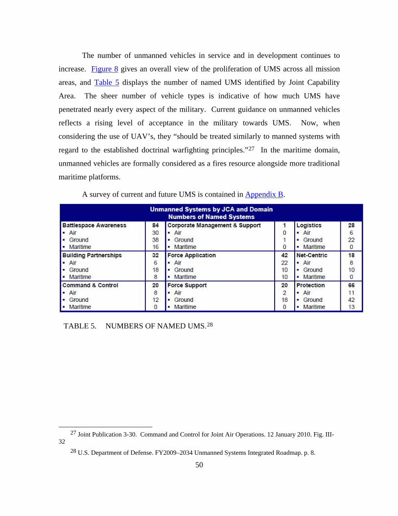
50
The number of unmanned vehicles in service and in development continues to
increase. Figure 8 gives an overall view of the proliferation of UMS across all mission
areas, and Table 5 displays the number of named UMS identified by Joint Capability
Area. The sheer number of vehicle types is indicative of how much UMS have
penetrated nearly every aspect of the military. Current guidance on unmanned vehicles
reflects a rising level of acceptance in the military towards UMS. Now, when
considering the use of UAV’s, they “should be treated similarly to manned systems with
regard to the established doctrinal warfighting principles.”27 In the maritime domain,
unmanned vehicles are formally considered as a fires resource alongside more traditional
maritime platforms.
A survey of current and future UMS is contained in Appendix B.
TABLE 5. NUMBERS OF NAMED UMS.28
27 Joint Publication 3-30. Command and Control for Joint Air Operations. 12 January 2010. Fig. III-
32 28 U.S. Department of Defense. FY2009–2034 Unmanned Systems Integrated Roadmap. p. 8.

51
Figure 8. Missions of Unmanned Systems29
3.2.2. Classes of UMS Classes of UMS
3.2.2.1. Unmanned Aerial Vehicles (UAV)
There are five categories of Unmanned Aerial Vehicles30, which are
distinguished by three primary parameters: Maximum Gross Takeoff Weight, Normal
Operating Altitude, and Speed. These categories are shown in Figure 9. With the
exception of Group 1, which have low altitudes and are typically small, and fly low and
29 Weatherington, Dyke D. “Unmanned Systems Roadmap” Presentation. Accessed 1 April 2010 at
http://www.dtic.mil/ndia/2007psa_peo/Weatherington.pdf 30 Joint Publication 3-30. Command and Control for Joint Air Operations. 12 January 2010. Fig. III-
15.
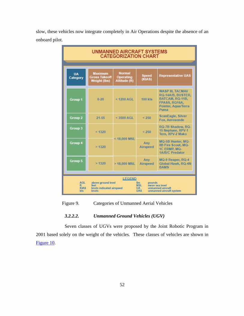
52
slow, these vehicles now integrate completely in Air Operations despite the absence of an
onboard pilot.
Figure 9. Categories of Unmanned Aerial Vehicles
3.2.2.2. Unmanned Ground Vehicles (UGV)
Seven classes of UGVs were proposed by the Joint Robotic Program in
2001 based solely on the weight of the vehicles. These classes of vehicles are shown in
Figure 10.
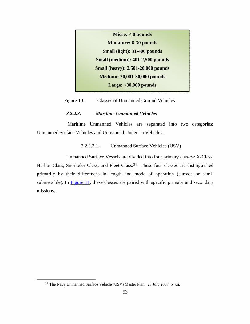
53
Figure 10. Classes of Unmanned Ground Vehicles
3.2.2.3. Maritime Unmanned Vehicles
Maritime Unmanned Vehicles are separated into two categories:
Unmanned Surface Vehicles and Unmanned Undersea Vehicles.
3.2.2.3.1. Unmanned Surface Vehicles (USV)
Unmanned Surface Vessels are divided into four primary classes: X-Class,
Harbor Class, Snorkeler Class, and Fleet Class.31 These four classes are distinguished
primarily by their differences in length and mode of operation (surface or semi-
submersible). In Figure 11, these classes are paired with specific primary and secondary
missions.
31 The Navy Unmanned Surface Vehicle (USV) Master Plan. 23 July 2007. p. xii.
Micro: < 8 pounds
Miniature: 8-30 pounds
Small (light): 31-400 pounds
Small (medium): 401-2,500 pounds
Small (heavy): 2,501-20,000 pounds
Medium: 20,001-30,000 pounds
Large: >30,000 pounds
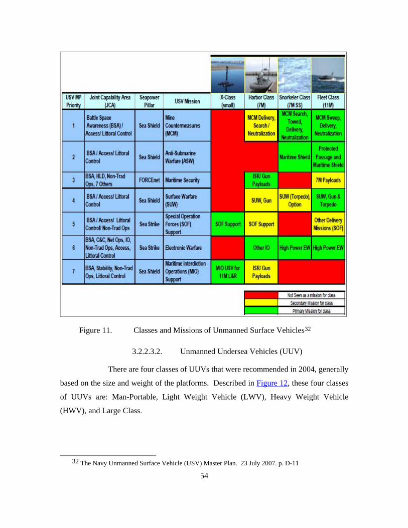
54
Figure 11. Classes and Missions of Unmanned Surface Vehicles32
3.2.2.3.2. Unmanned Undersea Vehicles (UUV)
There are four classes of UUVs that were recommended in 2004, generally
based on the size and weight of the platforms. Described in Figure 12, these four classes
of UUVs are: Man-Portable, Light Weight Vehicle (LWV), Heavy Weight Vehicle
(HWV), and Large Class.
32 The Navy Unmanned Surface Vehicle (USV) Master Plan. 23 July 2007. p. D-11

55
Figure 12. Parameters of Four Classes of Unmanned Underwater Vehicles33
3.2.3.4. Unmanned Outer Space Vehicles (UOSV)
There are no specific classes of unmanned outer space vehicles (UOSV),
but categories include satellites and resupply vehicles.
3.2.3. Implications of Using UMS
3.2.3.1. Advantages of UMS
There are many advantages to utilizing UMS for military applications.
• Protect human life: Unmanned vehicles can accomplish high
risk missions that would otherwise risk human life. For example,
in Iraq, many improvised explosive devises were detonated with
the help of unmanned ground vehicles. Unmanned vehicles
accomplish the dull, dirty, and dangerous missions that can put a
pilot’s life at risk.34
33 The Navy Unmanned Undersea Vehicle (UUV) Master Plan. 9 November 2004. p. 67. 34 Unmanned Aerial Vehicles: Background Issues for Congress, April 25, 2003, page 5,
http://www.fas.org/irp/crs/RL31872.pdf

56
• Reduce manpower: Unmanned vehicles can accomplish
missions that would otherwise require humans to be in manned
vehicles.
• Extend combat capabilities: Unmanned vehicles can supplement
a combat element and allow forward surveillance, strike, or other
combat capability.
• Increased time on station: Unmanned vehicles are not limited
by human endurance during missions.
• Generally smaller than manned platforms: Unmanned vehicles
do not have to account for human passengers and or comfort, thus
can be made smaller.
• Stowage ease: The smaller size of UMSs allows less stowage
space.
3.2.3.2. Disadvantages of UMS
While there are some strong advantages to using UMS, there are also
some disadvantages that must be recognized.
• Technology gaps: Machines have not been advanced to the
point where they can match human intelligence.
• Ethical questions: As more and more UMSs are utilized in
strike missions, the question arises as to when can a machine kill a
human on its own?
• Command and Control challenges: Current technology
limits control of UMSs to one controller per UMS. As more and
more unmanned vehicles are used, many UMSs must be able to be
controlled by a common controller.
• Flexibility of mission: A human operated vehicle can adapt to the
environment and change its mission given the threat and tasking.
57
• Human is removed from the local OODA Loop. The human is
not in the scenario and must rely on sensor data that does not allow
first hand human involvement.
3.3. AUTONOMY LEVELS FOR UNMANNED SYSTEMS (ALFUS)
3.3.1. Definitions of Autonomy
3.3.1.1. Dictionary Definition of Autonomy
The condition or quality of being independent or self-governing.35
3.3.1.2. SEA-16 Definition of Autonomy
“Operations of an unmanned system (UMS) wherein the UMS receives its
mission from the human and accomplishes that mission with or without further Human-
Robot Interaction (HRI). The level of HRI, along with other factors such as mission
complexity, and environmental difficulty, determine the level of autonomy for the UMS.
Finer-grained autonomy level designations can also be applied to the tasks, lower in
scope than mission.” 36
3.3.2. ALFUS Framework
The autonomy of a UMS is “characterized by the missions that the system is
capable of performing, the environments within which the missions are performed, and
human independence that can be allowed in the performance of the missions.”
35 Marckwardt, Albert H. “Webster Comprehensive Dictionary, Encyclopedic Edition”, J.G. Ferguson
Publishing Company, Chicago, IL, 1997, p. 99. 36 Huang, Hui-Min, “Autonomy Levels for Unmanned Systems (ALFUS) Framework, Volume I:
Terminology”, Intelligent System Division, National Institute of Standards and Technology, Sept 2004, p. 8.
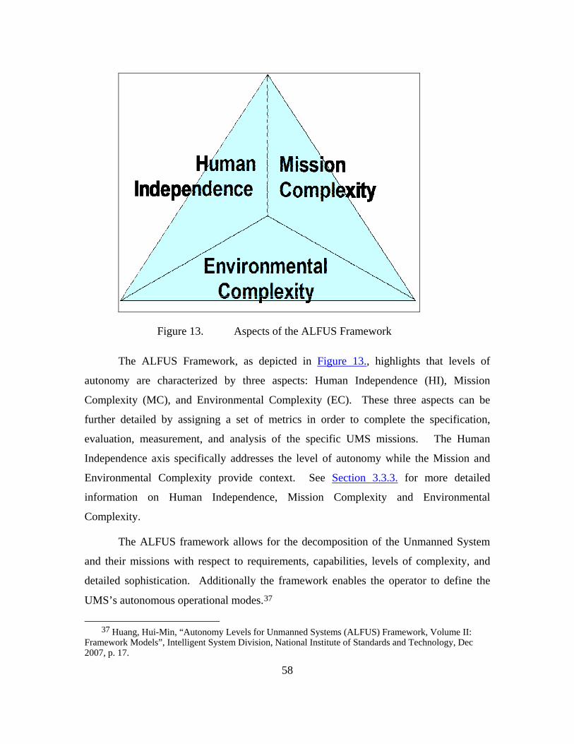
58
Figure 13. Aspects of the ALFUS Framework
The ALFUS Framework, as depicted in Figure 13., highlights that levels of
autonomy are characterized by three aspects: Human Independence (HI), Mission
Complexity (MC), and Environmental Complexity (EC). These three aspects can be
further detailed by assigning a set of metrics in order to complete the specification,
evaluation, measurement, and analysis of the specific UMS missions. The Human
Independence axis specifically addresses the level of autonomy while the Mission and
Environmental Complexity provide context. See Section 3.3.3. for more detailed
information on Human Independence, Mission Complexity and Environmental
Complexity.
The ALFUS framework allows for the decomposition of the Unmanned System
and their missions with respect to requirements, capabilities, levels of complexity, and
detailed sophistication. Additionally the framework enables the operator to define the
UMS’s autonomous operational modes.37
37 Huang, Hui-Min, “Autonomy Levels for Unmanned Systems (ALFUS) Framework, Volume II:
Framework Models”, Intelligent System Division, National Institute of Standards and Technology, Dec 2007, p. 17.

59
3.3.3. ALFUS Characteristics
Figure 14. ALFUS Characteristics38
The three aspects of Autonomy Levels for Unmanned Systems, as shown in
Figure 14., are analyzed by characteristics that determine the level of autonomy.
Human Independence (HI) is characterized by the frequency and duration of
robot initiated interactions, the workload and skill levels required for system operation,
and the operator to UMS ratio.
Mission Complexity (MC) can be characterized by the subtasks and decisions
required for the specific mission. Additionally, the organization, including the
collaboration with the organization, can be measured. The specific performance of the
UMS within the mission space can be used to characterize the Mission Complexity.
Finally, the allowed situational awareness and knowledge requirements can be used as a
metric.
Environmental Complexity (EC), probably the biggest unknown during
operations, is essential in determining the level of autonomy. The most common metrics
38 Huang, Hui-Min, “Autonomy Levels for Unmanned Systems (ALFUS)” brief, Intelligent System Division, National Institute of Standards and Technology, Dec 2007, p. 8.

60
for Environmental Complexity are terrain variation; object frequency, density and intent;
climate variability, mobility constraints; and communication limitations and
dependencies.
3.3.4. ALFUS and Bandwidth
An additional topic of study was to determine the correlation between ALFUS
and the amount of bandwidth required to support operations. As shown in Figure 15., the
amount of bandwidth required is directly related to the amount of Operator Authority
needed to control the UMS. High Operator Authority will require constant
communication between the operator and the UMS this in turn will require large amounts
of bandwidth for the transmission of control data. As shown, there is an inverse
relationship between Operator Authority and Computer Autonomy (for example the
lower requirement for Operator Authority the higher the allowable Computer Autonomy);
therefore there is also an inverse functional relationship between ALFUS and bandwidth.
Additionally, with low bandwidth (high autonomy) the communications cost will
be low, due to reduced equipment usage, but software expenditures will be big due to the
large cost of developing high levels of autonomy. With high bandwidth (low autonomy)
the software costs will be low, due to low development costs, but the communication
costs will be high due to the requirement for versatile equipment.

61
Figure 15. ALFUS vs Bandwidth.

62
3.3.5. Autonomy Levels for Unmanned Systems (ALFUS)
As shown in Table 6 &7 (ALFUS Levels 5-10 and 0-4)39, Autonomy Levels for
Unmanned Systems has been broken down to levels 0 – 10, covering Remotely Piloted
Vehicles to Fully Autonomous Vehicles. Each level has been detailed further by the
Level Descriptor and the OODA (Observe, Orient, Decide and Act) Loop. Each table
defines the levels with reference to the OODA Loop; allowing for the classification of
each UMS capability to a specific autonomy level. These autonomy levels are essential
in developing and running the simulations to test the overall architecture. As one of the
inputs to the simulation, an accurate accounting of each UMS’s autonomy level is
essential due to the communications demand requirements per vehicle.
39 Huang, Hui-Min, “Autonomy Levels for Unmanned Systems (ALFUS)” brief, Intelligent System
Division, National Institute of Standards and Technology, Dec 2007, p. 25.

63
Level Level Descriptor Observe Orient Decide Act
Perception/Situational Awareness Analysis/Coordination Decision Making Capability
10 Fully Autonomous Cognizant of all within Battlespace Coordinates as necessary Capable of total indepenance Requires little guidance to do job
Distributed tactical group planning
Individual determination of tactical goal
Individual task planning/execution
Choose tactical targets
Proximity inferance - intent of self and others (allies and foes)
Strategic group goals assigned Coordinated tactical group planning
Individual task planning/execution
Reduced dependance upon off-board data
Enemy tactics inferred Choose targets of opportunity
Tactical group goals assigned
Limited inference supplemented by off-board data
Tactical group goals assigned
Enemy location sense/estimated
Tactical group plan assigned
Collision avoidance Air collision avoidance
Group diagnosis and resource management
8 Battlespace Cognizance Group accomplishment of strategic goal with minimal supervisory (example: go SCUD hunting)
9 Battlespace Swarm Cognizance
Battlespace Inference - Intent of self and others (allies and foes)
Complex/intense environment - on-board tracking
Strategic group goals assigned
Enemy strategy inferred
Group accomplishment of strategic goal with no supervisory assistance
5
Short track awareness - History and predictive battlespace data in limited range, timeframe, and numbers Enemy trajectory estimated
Individual task planning/execution to meet goals
Coordinated tragectory planning and exectution to meet goal - group optimization
Ranged awareness - on-board sensing for long range, supplemented by off-board data
Sensed awareness - Local sensors to detect others, fused with off-board data
RT Health diagnosis; ability to compensate for most failures and flight conditions; Ability to predict onset of failures (eg Prognositic Health Mgmt)
On-board trajectory replanning - optimizes for current and predictive conditions
7 Battlespace Knowledge
Real Time Multi-Vehicle Cooperation
6
Possible close air space separation (1 - 100 yds) for AAR, formation in non-threat conditions
Group accomplishment of tactical plan as externally assigned
Group accomplishment of tactical goal with minimal supervisory assistance
Group accomplishment of tactical goal with minimal supervisory assistance
Real Time Multi-Vehicle Coordination
TABLE 6. ALFUS LEVELS 5-10.40
40 http://www.isd.mel.nist.gov/projects/autonomy_levels/ALFUS-Bg-web2.pps
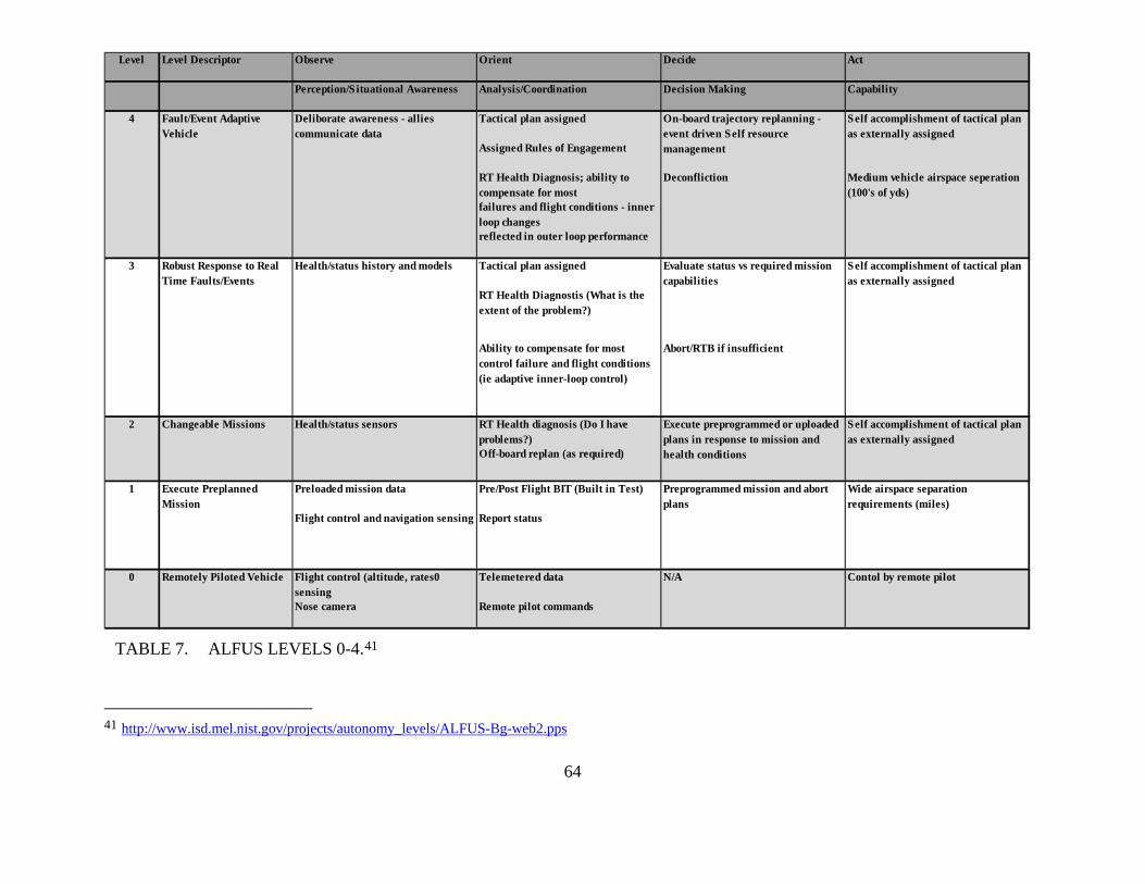
64
Level Level Descriptor Observe Orient Decide Act
Perception/S ituational Awareness Analysis/Coordination Decision Making Capability
Tactical plan assigned
Assigned Rules of Engagement
RT Health Diagnosis; ability to compensate for most
Deconfliction
failures and flight conditions - inner loop changesreflected in outer loop performance
Tactical plan assigned
RT Health Diagnostis (What is the extent of the problem?)
RT Health diagnosis (Do I have problems?)Off-board replan (as required)
Preloaded mission data Pre/Post Flight BIT (Built in Test)
Flight control (altitude, rates0 sensing
Telemetered data
Nose camera Remote pilot commands
Ability to compensate for most control failure and flight conditions (ie adaptive inner-loop control)
Self accomplishment of tactical plan as externally assigned
Self accomplishment of tactical plan as externally assigned
Medium vehicle airspace seperation (100's of yds)
On-board trajectory replanning - event driven Self resource management
Abort/RTB if insufficient
Evaluate status vs required mission capabilities
Contol by remote pilotN/A
Preprogrammed mission and abort plans
Wide airspace separation requirements (miles)
Report status
Execute preprogrammed or uploaded plans in response to mission and health conditions
Self accomplishment of tactical plan as externally assigned
0 Remotely Piloted Vehicle
Execute Preplanned Mission
Changeable Missions
Robust Response to Real Time Faults/Events
Health/status history and models
Health/status sensors
Flight control and navigation sensing
Deliborate awareness - allies communicate data
Fault/Event Adaptive Vehicle
3
4
2
1
TABLE 7. ALFUS LEVELS 0-4.41
41 http://www.isd.mel.nist.gov/projects/autonomy_levels/ALFUS-Bg-web2.pps

65
Figure 16. ALFUS Simplification42
In order to simplify the simulation the Autonomy Group used the model
developed by the National Institute of Standards and Technology. As shown in Figure
16., the eleven separate levels are further decomposed into three main levels (Low,
Medium, and High). To accomplish this, the extreme levels 0 and 10 were removed (due
to the lack of applicability for this project) and the remaining nine levels were grouped
into three levels. This reduction of complexity simplified the simulation phase of the
project. Each of the three levels was defined by the amount of Human Interaction (HI),
Mission Complexity (MC), and Environmental Complexity (EC).
42 Huang, Hui-Min, “Autonomy Levels for Unmanned Systems (ALFUS)” brief, Intelligent System
Division, National Institute of Standards and Technology, Dec 2007, p. 25
66
3.4. MAN IN THE LOOP ANALYSIS
To determine the role of humans and machines within a sophisticated system, it
was necessary to examine the general characteristics of humans and machines in order to
better understand where their capabilities within a process should be allocated. Both
have inherent qualities that can be exploited within a system to provide the greatest
utility. Equivalently, they have weaknesses that system design should attempt to
marginalize. Within a Command and Control system, all of these qualities can affect
every level of functionality, and when they are well-balanced, a truly efficient system
design can be realized.
Currently, there are three basic categories of functional allocation for humans and
machines.43
• Comparison allocation
• Leftover allocation
• Economic allocation
Comparison allocation is a method of making general comparisons of human and
machine capabilities in order to allocate system functions. Leftover allocation is
primarily a vehicle for assigning roles to humans where machines functionality does not
exist. Economic allocation can be difficult to perform, due to the various costs that must
be identified and considered, but allocation is quantitative, and not a “judgment” by the
systems architect. Comparison allocation is more complicated than either Leftover or
Economic allocation, as the decision on whether a human or machine should perform a
function is purely a qualitative judgment. Inagaki states there is a need for “a systematic
way of thinking and methodology that can investigate and evaluate design of human-
machine collaborations in a quantitative manner with appropriate precision.” This man-
in-the-loop analysis was performed to identify concepts and methods that can be applied
while conducting Comparison allocation.
43 Inagaki, T. Human-Machine Collaboration for Safety and Comfort. Presented to ENRI International
Workshop on ATM/CNS. 2009. p. 1.

67
3.4.1. Human and Machine Strength Comparison
For many years, scholars have attempted to compare the strengths and weaknesses
of humans to those of machines. One of the pioneers in this research was Paul M. Fitts.
In 1951, he developed one of the first lists that identified the strengths of humans and
machines with respect to one another. Fitts’ simple comparison is shown in Figure 17.
Figure 17. Fitts’ List44
The Department of Defense Human Engineering Program Processes and
Procedures is a modern take on this subject.45 This listing, shown in Figure 18. and
44 Buede, Dennis M., The Engineering Design of Systems: Models and Methods. John Wiley & Sons,
New York, NY. p. 253. 45 U.S. Department of Defense. MIL-HDBK-46855A (Human Engineering Program Processes and
Procedures). 17 May 1999. p. 153.
Humans appear to surpass present-day machines with respect to the following:
• Ability to detect small amounts of visual or acoustic energy
• Ability to perceive patterns of light or sound
• Ability to improvise and use flexible procedures
• Ability to store very large amounts of information for long periods and to
recall relevant facts at the appropriate time
• Ability to reason inductively
• Ability to exercise judgment
Present day machines appear to surpass humans with respect to the following:
• Ability to respond quickly to control signals, and to apply great force
smoothly and precisely
• Ability to perform repetitive, routine tasks
• Ability to store information briefly and then to erase it completely
• Ability to reason deductively, including computational ability
• Ability to handle complex operations, i.e. to do many different things at once
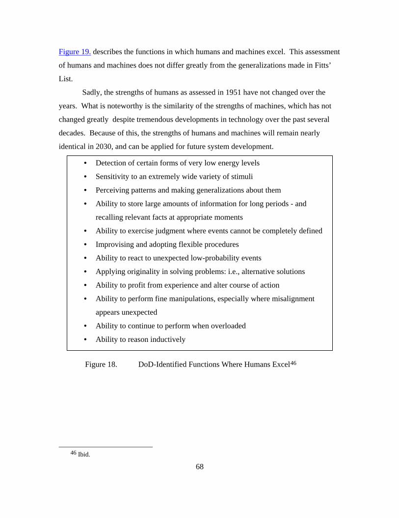
68
Figure 19. describes the functions in which humans and machines excel. This assessment
of humans and machines does not differ greatly from the generalizations made in Fitts’
List.
Sadly, the strengths of humans as assessed in 1951 have not changed over the
years. What is noteworthy is the similarity of the strengths of machines, which has not
changed greatly despite tremendous developments in technology over the past several
decades. Because of this, the strengths of humans and machines will remain nearly
identical in 2030, and can be applied for future system development.
Figure 18. DoD-Identified Functions Where Humans Excel46
46 Ibid.
• Detection of certain forms of very low energy levels
• Sensitivity to an extremely wide variety of stimuli
• Perceiving patterns and making generalizations about them
• Ability to store large amounts of information for long periods - and
recalling relevant facts at appropriate moments
• Ability to exercise judgment where events cannot be completely defined
• Improvising and adopting flexible procedures
• Ability to react to unexpected low-probability events
• Applying originality in solving problems: i.e., alternative solutions
• Ability to profit from experience and alter course of action
• Ability to perform fine manipulations, especially where misalignment
appears unexpected
• Ability to continue to perform when overloaded
• Ability to reason inductively

69
Figure 19. DoD-Identified Functions Where Machines Excel47
47 Ibid.
• Monitoring (both men and machines)
• Performing routine, repetitive, or very precise operations
• Responding very quickly to control signals
• Storing and recalling large amounts of information in short time-
periods
• Performing complex and rapid computation with high accuracy
• Sensitivity to stimuli beyond the range of human sensitivity (infrared,
radio waves.)
• Doing many different things at one time
• Exerting large amounts of force smoothly and precisely
• Insensitivity to extraneous factors
• Ability to repeat operations very rapidly, continuously, and precisely
the same way over a long period
• Operating in environments which are hostile to man or beyond
human tolerance
• Deductive processes

70
3.4.2. Sources of Human and Mechanical Error
An additional consideration that must be made when allocating functions to
humans or machines is the general types of errors that are possible for each of them.
Table 8 lists common sources of human and machine error.
It is difficult to measure human error, especially because each human has
differing levels of experience, tolerance, and effort. Studies of mechanical error are
much more likely to be quantifiable, as components often meet exact specifications and
historical performance can be analyzed.
TABLE 8. SOURCES OF HUMAN AND MECHANICAL ERROR.
3.4.3. Command and Control Considerations
The strengths of humans and machines can be allocated to the four phases within
Boyd’s OODA Loop, as shown in Table 9. What is noticeable immediately is the great
versatility of humans in the “Decide” category, and the greater range of strengths for
machines in the “Act” category. These qualities do not imply that humans or machines
are preferred for any single phase of this Command and Control methodology. Any
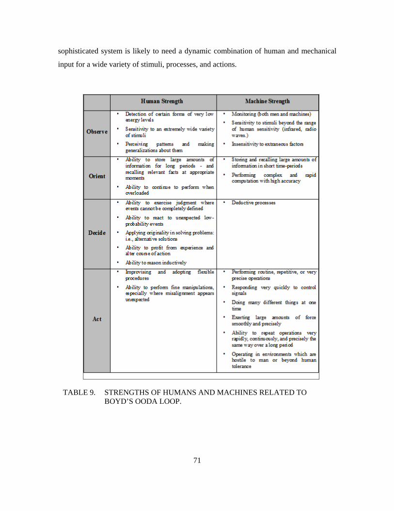
71
sophisticated system is likely to need a dynamic combination of human and mechanical
input for a wide variety of stimuli, processes, and actions.
TABLE 9. STRENGTHS OF HUMANS AND MACHINES RELATED TO BOYD’S OODA LOOP.

72
3.4.4. Functional Performance Role Allocation
H.E. Price proposed a simple methodology to determine whether a function
should be allocated to a human or to a machine.48 Functions are scaled in his model,
shown in Figure 20., based on the each of their levels of performance, rated from
Unsatisfactory to Excellent, and plotted on a simple two-dimensional axis. This model is
highly reliant on the judgment of the decision maker, and on consistent decisions between
multiple decision makers.
Figure 20. Price’s Comparison Methodology for Allocating Roles to Humans or Machines49
48 Price, H. E. The Allocation of Functions in Systems. Human Factors. Vol 27, No. 1.1985. p. 33-45. 49 Price, H. E. The Allocation of Functions in Systems. Human Factors. Vol 27, No. 1.1985. p. 33-45.

73
Below is a description of the generalized relationships that are mapped on Price’s
Scale:
1. Little difference in human and machine; choice made on the basis of
criteria other than relative performance.
2. Human performance exceeds machine performance; the decision should
be made by the human.
3. Machine exceeds human performance; decision should be made by the
machine.
4. Poor Machine performance; decision should be allocated to humans.
5. Poor Human performance; decision should be allocated to machine.
6. Unacceptable for both human and machine, arguing for a different design
approach.
3.4.5. Current Decision Methodology
There is no definitive accepted process in determining whether or not a mission
should be completed by a manned unit or an unmanned unit. Figure 21. shows a process
currently used to make this decision. This process was provided by the office of
OPNAVN812D.50
50 Email from CDR Edward J. McDonald OPNAV N812D, Integration Pentagon, Room 4D453 (703)
614-0280 DSN 224-0280 [email protected] Mon 3/8/2010 6:38 AM

74
Figure 21. Example of Current UMS System Decision Tree51
This decision process requires the decision maker to make choices based on
several general themes. Ultimately, costs are a major constraint that will need to be
analyzed after major functional drivers are evaluated.
In future integrated vehicle architecture, differing levels of autonomy based on the
ALFUS framework will be required at each node in the system. All systems will have
varying degrees of autonomy.
51 Email from CDR Edward J. McDonald OPNAV N812D, Integration Pentagon, Room 4D453 (703)
614-0280 DSN 224-0280 [email protected] Mon 3/8/2010 6:38 AM

75
3.4.6. Human Machine Collaborative Decision Making (HMCDM)
The designs of systems where humans and machines collaborate have been
modeled after human processes, which are augmented by mechanical capabilities.
Malasky asserts that “Future C2 planning systems can be improved if the humans and
machines are integrated fully in a way that takes advantage of the strengths of both.”52
This HMCDM experiment proposes that collaboration should be designed from the
beginning of the decision making process, and demonstrated the potential for
improvement in the quality and speed of solutions to a military planning problem.53
When humans and machines are capable of collaborative decision making, the
question still remains, “Who is in charge?” If a human operator is designated to have
overarching authority, then the capability for a machine to override the human operator
must also be considered. This paradigm is illustrated in Figure 22.54 Assuming human
operator control authority, Region A shows machine recognition that an action was not
taken when it should be taking place, and Region B shows the recognition by the machine
of inappropriate actions being taken by the human. Recognizing these possible results,
the decision maker must choose whether or not to allow mechanical intervention, and
whether human operators should still have the ability to override the corrective action
based on human factors of interpretation.
52 Malasky, Jeremy S. Human Machine Collaborative Decision Making in a Complex Optimization
System. 12 May 2005. p. 146. 53 Malasky, Jeremy S. Human Machine Collaborative Decision Making in a Complex Optimization
System. 12 May 2005. p. 145. 54 Inagaki, T. Human-Machine Collaboration for Safety and Comfort. Presented to ENRI International
Workshop on ATM/CNS. 2009. 3.
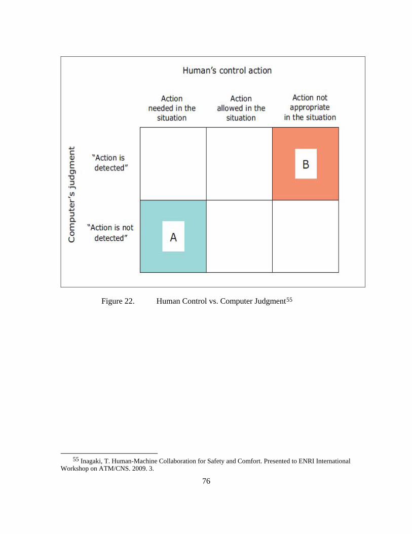
76
Figure 22. Human Control vs. Computer Judgment55
55 Inagaki, T. Human-Machine Collaboration for Safety and Comfort. Presented to ENRI International
Workshop on ATM/CNS. 2009. 3.
77
3.5. INFORMATION ASSURANCE CONSIDERATIONS FOR C2 ARCHITECTURE
The confidentiality, integrity, and timely availability of information is enabled by
encryption, frequency shifting and system redundancies often play an important part in
the success of military operations. This section seeks to find ways to safeguard
information assets by examining problems from an information assurance perspective.
3.5.1. Identity and Key Management
Identity management is crucial to any large scale organization in
managing the effectively accesses of individuals to its resources. The conventional
identity management concept deals with managing the identities of individuals in a
system. In an Unmanned Vehicle (UV) scenario, the individuals dealt with are no longer
humans. The scope of identity management will thus have to be extended beyond human
subjects.
One of the most important requirements for identity management is to
identify a subject uniquely. For human subjects, the focus was on “what we are” (e.g.
biometrics such as fingerprint or facial features), “what we have” (e.g. tokens such as
smart card) and “what we know (e.g. password) to uniquely identify an individual. For
UVs, the simplest implantation would probably have to be in the form of a “secret” that
only the UV knows. The system would have to trust that once a UV proved that it has
knowledge of a unique “secret”, it is who it claims to be. This “secret” can be in the form
of a cryptographic key stored in a tamper proof device embedded inside the UV.
Lifecycle of a UV
A good identity management system would have to take care of the entire
lifecycle of the subjects.
A secret key would have to be generated during the production of a UV in
a secure manner. This key would have to be unique cryptographically and stored in a
tamper proof device in such a manner that any attempts to tamper with the device would
result in the destruction of the key. A feasible implementation of such a mechanism
would be an asymmetric key pair where the private key is stored inside a tamper-proof

78
chip embedded inside the UV and the public key is tied to the identity of the UV in a
central identity management database in the system.
Just like a clearance level is given to each human individual, each UV may
be given a clearance level (unclassified, secret, top secret) that identies the information
that they are allowed to access. An alternative implementation would be a role-based
mechanism where each UV is assigned a specific role and the resources are tied to the
role that they are assigned to. The UV may switch to a number of different roles
throughout its lifecycle and the system must be designed to accommodate this change.
A common database scheme would have to be established to allow
different types of unmanned vehicles to be enrolled into an enterprise wide identity
management system and for keeping track of all the keys embedded inside each
unmanned vehicle. A separate key management system and Public Key Infrastructure
might be necessary to support the deployment and management of keys to the unmanned
vehicles.
Once a UV is retired, destroyed, compromised, or transferred out of the
system, the identity management system would have to terminate its associated account
and privileges to make sure no other individual is able to make use of that identity to gain
unauthorized access to the system.
3.5.2. High Assurance Internetworking
The goal of high assurance internetworking is to protect the
confidentiality, integrity and availability (CIA) of information while in transit across the
network. At the same time, attacks against the network have to be identified and blocked.
Cryptography (Encryption, hashing and digital signatures) is used to provide the
protection of the data as it transits the network while traffic filtering (firewalls, intrusion
detection) is used to protect the network against attacks.
The amount of protection required for various data types is identified and
tabulated in OV3. The following factors were considered:

79
• Confidentiality The confidentiality of data is usually
protected by performing encryption. However, performing
encryption on large amounts of data can cripple the performance of
the system. As such, data such as live video feed would not be
encrypted.
• Integrity The integrity of the data can be provided by
performing hashing on the data along with digital signatures.
Control data sent to UVs need to have high integrity to prevent
aggressors from hijacking the UVs.
• Availability Availability can be provided by introducing
redundancies in the system. The level of availability required in the
system is decided by the criticality and timeliness requirements of
the system.
Additional features could be implemented in the system to improvement
the assurance of the network. The security data from diverse sources across the networks
can be aggregated and normalized to provide a holistic view of the network health and
status. A business intelligence framework could also be utilized to maximize the
usefulness of historical and near real-time network defense data. Capabilities could be
developed to detect non-traditional forms of network intrusion. In addition, some form of
visualization could also be implemented to provide better awareness of the network
topology and detected intrusions.56
3.5.3. Tamper-Proof Device
There are two aspects of tamper proof devices. A tamper-evident device
provides a lower level of security than a tamper-resistant device since the former only
detects evidence of unauthorized access to the protected device while the latter prevents
56 Network Security Section, http://www.nrl.navy.mil/chacs/5544/.

80
unauthorized access of the protected device. Having a tamper-resistant device is more
relevant than having a tamper-evident device for the UMS in this architecture.
The two scenarios in this project, reconnaissance and force protection,
require extensive data collection as part of the operation. It is important that the storage
device be tamper-resistant. Requirements for tamper-resistant storage within the UMS
are:
• Weight of device – lightweight is preferred as additional
increase in weight affects the payload of the unmanned
vehicles
• Power consumption – unmanned vehicles can only operate as
long as their batteries allow, so additional increase in power
consumption will reduce the operating time of the unmanned
vehicles
• Data storage space – having a large data storage space means
able to collect more data for analyzed.
• Robustness – device must not fail under harsh environment
conditions
• Authenticity guarantees – ensuring authorized access to the
device
• Confidentiality guarantees – ensuring data in the device are not
able to be viewed by unauthorized access
• Integrity guarantees – ensuring that data in the device are not
modified
• Performance overhead to security – having an enhanced
encryption algorithm requires more computation power which
adds on to the power consumption of the device. On the other
hand, having a basic, simple encryption algorithm may lower
the security level of the device
81
While there are ready tamper-resistant secure storage devices available
commercially, there are still some research challenges for tamper-resistant devices. They
are:
• Protect Confidentiality of information - looking at enhanced
methods to prevent unauthorized users from viewing data and
exploring reverse-engineering protection mechanism
• Protect Functional Integrity - ensure device performs its intended
function and does not allow device to be tampered, and
enhancement of secure processors architecture
• Protection against unauthorized copying or modification -
verification methods to check valid changes of new versions of
data
• Authenticity guarantees - establishing and maintaining origin of
data as well as exploring methods to associate signatures with data
and establishing versioning for data fragments
• Scalability - able to handle/manage large size file system, number
of users, number of processes; design small form factor devices
and yet support expansion (scalability)
• Performance overhead - techniques for lowering performance
overheads for cryptography ciphers; design enhanced ciphers to
include parallelism
Optimistically, some of these challenges can be addressed with
technological advancements in the coming future. More importantly, having tamper-
resistant secure storage to be implemented in unmanned vehicles is a small step towards
information operational assurance of the system.57
57 Elizabeth Haubert Joseph , Joseph Tucek , Larry Brumbaugh , William Yurcik, “Tamper-Resistant Storage Techniques for Multimedia Systems,” In IS&T/SPIE International Symposium Electronic Imaging / Storage and Retrieval Methods and Applications for Multimedia. 2005.

82
3.5.4. Availability and Denial of Service
The UVs will operate in a rich collaborative information environment that
is potentially hostile. Hardware failures, resource exhaustion, environmental conditions,
or any complicated interaction between these factors can affect the availability of the
system. The adversary may launch denial of service attacks by manipulating the
environment so as disrupt communication, for example by jamming our communications
from a distance or put themselves in the networks and disrupt infrastructure functions and
lines of communications, such as routing of message performed by the individual nodes.
In addition, the communications infrastructure may be unable to handle the heavy
demands where many messages are routed for synchronization of activities, sharing of
information and collaboration. The impact is degradation in situational awareness and
defense capabilities in both scenarios.
The architecture should be resilient against noise and provide robust anti-
jamming capabilities to defeat jamming attacks. In addition, solutions must be developed
to authenticate nodes and defend against resource exhaustion, flooding attacks to waste
bandwidth and energy, traffic redirections and other forms of denial of service attacks.
Factors such as frequency allocation, radiated power, battery life, and organizational lines
of communications should also be analyzed.
Assuming large scale deployment of cheap nodes, the network should be
resilient to individual node failure as a node may fail at any time. Node failure may be
due to hardware or software failure, end of battery life, compromised or destroyed by the
adversary. The architecture should allow new nodes to be added to the network to
replace a failed node. New nodes may also be introduced to enhance system
performance, e.g. to increase the operating range. These nodes should be integrated
seamlessly into the existing network without impacting overall performance.
The adversary may intercept and subvert a node in the network or
introduce their own nodes to disrupt our operations. Strong authentication and tamper-
proof technologies must be developed to increase the assurance that a node has not been
compromised and that it has been authorized to participate in the network. These

83
mechanisms must be economical and must take into account the overall payload and
battery life that the UVs can support. Messages should also be authenticated without
introducing too much overhead and slowing down the operation to unacceptable levels.
The ability to detect and react against a denial of service attack is critical to the
availability of assets. The architecture should at least provide the means to report the
incident of an attack to the operator for man-in-the loop intervention. Development of
self-healing capabilities will further improve service availability by discovering,
diagnosing, and reacting autonomously to network disruptions. Self-healing components
will detect system malfunctions (accidental or deliberate) and start corrective actions
based on defined policies to recover the network or a node, thus automatically recovering
from damages. Algorithms to be developed include election and activation of backup
nodes, re-routing to the next available nodes and coordinating physical re-location of
nodes. These algorithms must be as efficient as possible since the UVs will have low
processing power, even though it was expected that hardware processing power to
increase tremendously by 2030.
84
3.6. ENGINEERING ASSESSMENT OF CAPABILITIES UNMANNED SYSTEMS: ENGINEERING FOR 2030
3.6.1. Introduction
Current trends of sustainable energy, “greener” emission friendly energy
resources and overall efficiency as a financial driver can be seen through a majority of
civilian and military projects. It would come to no surprise that the military will help
lead the way in ground-breaking research and application of new technologies.
Trade studies wereconducted to explore the technology area’s most beneficial to
unmanned systems. Specifically, engine cycle efficiency, advanced fuels, and fuel
cell/battery power systems were studied. The trade study emphasized maximizing a
specific unmanned systems’ ability to stay on station (longer endurance).
3.6.2. Fuel Cycle Efficiency
3.6.2.1. Internal Combustion Engines
With perhaps the lowest of cycle efficiencies, internal combustion
engines still have a stake in military platforms. The MQ-1 Predator, runs off of a turbo-
charged ROTAX 912 four stroke engine. With an average efficiency of 25% (broadly
speaking), the internal combustion engine, described by the Otto cycle, can be improved
by improving internal combustion efficiency (expected to reach levels as high as 40%,
15% higher than current designs). The technology driving these high efficiency gains can
be found in ground-breaking engine designs.
The most publicized engineering success in the area has been the Scuderi
Split Cycle Engine. While the split-cycle design has been around since 1914, it has been
plagued by low volumetric efficiency and low thermal efficiency.58 The Scuderi Group
has solved the “breathing” problem of volumetric efficiency on the compression side by
reducing the clearance between the piston and the cylinder head to less than 1 mm.59 The
58 Scuderi Engine, “Why is the Scuderi Split Cycle Engine Better?” http://www.scuderiengine.com/
(accessed April 23, 2010). 59 Ibid.
85
design alteration described, effectively pushes almost 100 percent of the compressed air
from the compression cylinder into the crossover passage, eliminating the breathing
problems associated with previous split-cycle engines.60
With regard to thermal efficiency, the split-cycle has to date been
significantly worse than in a conventional Otto cycle engine because previous designs
maintained firing before top-dead-centre (BTDC) - like a conventional engine. In order to
fire BTDC in a split-cycle engine, the compressed air trapped in the crossover passage is
allowed to expand into the power cylinder as the power piston travels upwards.61
However, by releasing the pressure of the compressed air, the work done on the air in the
compression cylinder is lost. The power piston then has to recompress the air in order to
fire BTDC. In a conventional engine, the work of compression is done only once, leading
to much better thermal efficiency.62 In Scuderi's design, the thermal efficiency problem
has been solved by breaking from conventional design best practice and instead firing
after top-dead-centre (ATDC). Firing ATDC in a split-cycle arrangement eliminates the
losses resulting from recompressing the gas.63
Aside from split-cycle design, additional improvements to the internal
combustion engine are emerging. Radical designs such as the 5-stroke engine are
predicting efficiency increases up to 20%, and allowing for internal combustion engines
to match that of current highly efficient diesel engines. One engineering firm, Ilmor, has
brought this invention to light by introducing a 5-stroke engine prototype as a plausible
and working engineering design. According to Ilmor, the 5-stroke concept engine utilizes
two high-pressure fired cylinders operating on a conventional 4-stroke cycle that
alternately exhaust into a central low-pressure expansion cylinder, whereupon the burnt
gases perform further work. The low-pressure cylinder decouples the expansion and
60 Ibid. 61 Ibid. 62 Ibid. 63 Ibid.
86
compression processes and enables the optimum expansion ratio to be selected
independently of the compression ratio; leading to increased efficiency.64
3.6.2.2. Diesel Engines
One of the most surprising driving forces in more efficient engine cycles is
coming from Washington D.C. The passing of the U.S. EPA 2010 Emissions Standards
has greatly accelerated advancements in diesel technology. The EPA emissions standards
pose a significant challenge for developing clean diesel power-trains that are affordable.
Along with exhaust emissions, an emphasis on heavy-duty vehicle fuel efficiency is
being driven by increased energy costs as well as the potential regulation of greenhouse
gases.65 With the standards setting strict requirements on minimum engine efficiency,
companies such as Cummins Diesel have begin designing and implementing several
measures to improve their diesel engines. Three areas of emphasis that lead to substantial
improvements in engine thermal efficiency are the maximization of the engine closed
cycle efficiency, the reduction of open cycle losses and engine parasitics, and the
integration of Highly Efficient Clean Combustion (HECC) engine technology with after
treatment.66 Emphasis on areas highlighted by Cummins Diesel can lead to future diesel
efficiency upwards of 65% by the year 2030.
This focused attention on diesel engines will not just allow for more
efficient long-haul truck and tractor applications, but could possibly have ties to future
military systems. While diesel engines are not the preferred propulsion system for
unmanned air vehicles, they could have significant implications for future unmanned
surface vessels and underwater vehicles.
64 Ilmor Engineering, “The 5-Stroke Concept Engine,” http://www.ilmor.co.uk/concept_5-
stroke_1.php (accessed April 22, 2010) 65 Energy Efficiency and Renewable Energy Office “Advanced Combustion Engine Research and
Development 2009” (paper presented at the annual progress meeting for the U.S. Department of Energy, Washington D.C., December 2009).
66Ibid

87
3.6.2.3. Gas Turbines
Gas turbine cycles currently serve as one of the military’s prime movers.
From naval surface ships, to unmanned Global-Hawk aerial surveillance platforms, gas
turbines have a significant stake in propulsion. Much like the advancements of internal
combustion and diesel engine cycles, the gas turbine will be able to become more
efficient over the next two decades. For efficiency increase to occur, the gas turbine
needs to be examined in its most simple representation; the Brayton cycle. For gas
turbines, the Brayton cycle can be analyzed as simple or combined.
Simple and combined gas turbine cycle diagrams are shown in Figure 23.
below. The Brayton cycle can be characterized by two important parameters: pressure
ratio and inlet temperature. The pressure ratio of the cycle can be described as the
compressor discharge pressure divided by compressor inlet pressure.67 However, in an
actual cycle there is some slight pressure loss in the combustion system and thus the
pressure at the combustor discharge is less than the combustor inlet. The other
significant parameter, turbine inlet temperature, is thought to be the highest temperature
reached in the cycle.
67 Frank Brooks, “GE Gas Turbine Performance Characteristics,” GE Power Systems- GER3567H

88
Figure 23. Comparison of Simple & Combined Cycles68
68 Ibid.

89
In simple-cycle applications (the top curve), pressure ratio increases
translate into efficiency gains at a given inlet temperature. However, for combined-cycle
systems, as shown in the bottom of Figure 23., pressure ratio increases have a less
pronounced effect on efficiency.69 Note also that as pressure ratio increases, specific
power decreases. Increases in the turbine inlet temperature result in increased thermal
efficiency. Simple-cycle efficiency is achieved with high pressure ratios. Combined-
cycle efficiency is obtained with more modest pressure ratios and greater firing
temperatures.
3.6.2.4. Pulse Detonation Engines (PDEs)
Still in development, pulse detonation engine technology is being pursued
as the means to achieve more efficient high-speed flight. PDEs offer an alternative
source of propulsion to current turbojet and ramjet/scramjet systems, by incorporating
nearly constant volume combustion vice constant pressure combustion, which governs
Brayton cycle operations.70 The cycle is shown in Figure 24. In a PDE, the combustion
chamber is filled with a fuel/air mixture and detonated. A detonation wave propagates
through the chamber creating high pressures that produce thrust.71 Products of
combustion are exhausted and the cycle starts again. Either running this cycle at high
frequencies or coordinating multiple combustion chambers can produce quasi-steady
thrust.72
69 Brooks, Frank., “GE Gas Turbine Performance Characteristics,” GE Power Systems- GER3567H
70 B. Bartosh, “Thrust Measurement of a Split-Path, Valveless Pulse Detonation Engine” (MSME Thesis, Naval Postgraduate School, 2007) 13
71 Hutchins, T.E. and Metghalchi, M. “Energy and Exergy Analyses of the Pulse Detonation Engine” North Eastern University ASME Vol 125. October 2003.
72 Ibid.

90
Figure 24. The Pulse Detonation Engine Cycle73
This type of combustion produces two beneficial results, higher
temperature increase and higher pressure. The higher combustion pressures (compared to
Brayton Cycle), and a lower entropy rise, result in a total enthalpy increase; thus allowing
for efficiency increases of 25-35% over typical Brayton cycles.74 Overall PDE cycle
efficiency is estimated to be as high as 55% by 2030. Figure 25., shows the comparison
of the Brayton cycle to the Humphrey cycle, which best models pulse detonation engine
systems.
73 Ibid.
74 Bartosh, B., “Thrust Measurement of a Split-Path, Valveless Pulse Detonation Engine” (MSME Thesis, Naval Postgraduate School, 2007) 13

91
Figure 25. Comparison of Humphrey and Brayton Cycles75
Currently, the application of PDE technology is more suited for cruise
missile type platforms, but further advancements and design of unmanned platforms
could see the application of PDE to the design of unmanned systems.
3.6.2.5. Constant-Volume-Combustion (CVC) Hybrid Engines
The Defense Advanced Research Projects Agency (DARPA) has invested
resources in a program focused on combined-cycle propulsion system architecture, with
separate CVC and turbine engines, intended for high-Mach military aircraft.76 This
program, titled “Vulcan,” is one of the most specific applications of the CVC concept.
The “Vulcan” is the combination of a turbojet and a CVC process. Constant volume
combustion technology can be integrated into a turbine engines through many different
architectures – a combined-cycle propulsion system with a separate CVC engine and a
turbine engine sharing a common inlet and common nozzle; CVC engine integrated into a
75 Ibid. 76 “Constant Volume Combustion (CVC) Technology for Vulcan Program Phase II” Solicitation
Number: DARPA-SN-09-70 https://www.fbo.gov/index?s=opportunity&mode=form&id=31f9542e9eaf99222a1bb41c12a692a4&tab=core&_cview=1

92
turbine engine fan duct; CVC engine integrated into a turbine engine augmenter; and a
hybrid system, where a turbine engine combustor is replaced with a CVC module.77 All
of the aforementioned architectures greatly improves the performance and increases the
capability of turbine engines.
Constant volume combustion systems have the potential to significantly
decrease the fuel consumption of U.S. Navy air and surface combatants (manned and
unmanned platform) and provide increased capability.78 Specifically for naval surface
applications, the CVC-hybrid engine will be smaller in terms of output and size relative
to the propulsion turbine units, but the ship power turbine units will consume only half
the fuel originally required.79 Capabilities of U.S. Navy surface vessels continue to grow
due to the need to incorporate more capable and numerous defensive and offensive
systems to address new threats and missions; replacing conventional combustors and
integration of CVC into the power generation gas turbines on these vessels promises
additional ship electrical power and lower Specific Fuel Consumption (SFC).80
3.6.2.6. Forecast of Cycle Efficiency Increases
The focus of the above trade study was to gather information to best
extrapolate the efficiencies of several different engine cycles involved with military
platforms. In order to best predict the future, current technology needed to be established
as a reference point. Figure 26. shows the average efficiency of all the previously
mentioned engine cycles over the next two decades. The efficiencies displayed in the
plot are forecasts of potential capabilities.
77 Ibid. 78 Ibid.
79 Warwick, Graham “DARPA Lifts the Covers on the Vulcan Engine Program” posted June 6, 2008, http://www.aviationweek.com/aw/blogs/defense/index.jsp (acessed May , 2010).
80 Ibid.
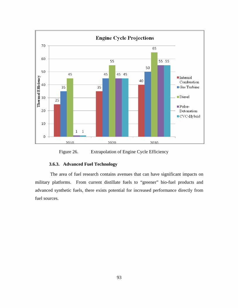
93
Figure 26. Extrapolation of Engine Cycle Efficiency
3.6.3. Advanced Fuel Technology
The area of fuel research contains avenues that can have significant impacts on
military platforms. From current distillate fuels to “greener” bio-fuel products and
advanced synthetic fuels, there exists potential for increased performance directly from
fuel sources.

94
3.6.3.1. Distillate Fuel
Distillate fuel can be more commonly described as fuels that are
petroleum derived. Over the past one hundred years, petroleum based fuels have been
refined and produced to yield more efficiency and cleaner by-products. One of the most
measurable figures for fuels is the Net Heat of Combustion (by mass or volume). The
table below is tabulated for three different U.S. military jet fuels:
Fuel TypeYear
Introduced
Net Heat of Combustion By Weight
(kJ/kg
Net Heat of Combustion By Volume
(MJ/m3) ServiceJP-4 1951.0 43570 33190 U.S. Air Force FuelJP-5 1952.0 43050 35200 U.S. Navy FuelJP-8 1979.0 43240 35060 U.S. Air Force FuelJP-10 1993.0 42100 39582 U.S. Navy Fuel
TABLE 10. U.S. MILITARY JET FUEL LOOP.
From Table 10, it can be seen that for the past 50 years, there is not
significant or any improvement in terms of Net Heat of Combustion by Weight or by
Volume. With even this brief snapshot of fuels, it can be concluded that any
improvement from distillate fuel will most likely be insignificant.
3.6.3.2. Bio-Fuel
With an ever-increasing reliance on petroleum-based fuels, there is a need
to find an alternative to petroleum in order to reduce the dependency on foreign oil.
Figure below shows the projected reliance on petroleum imports:
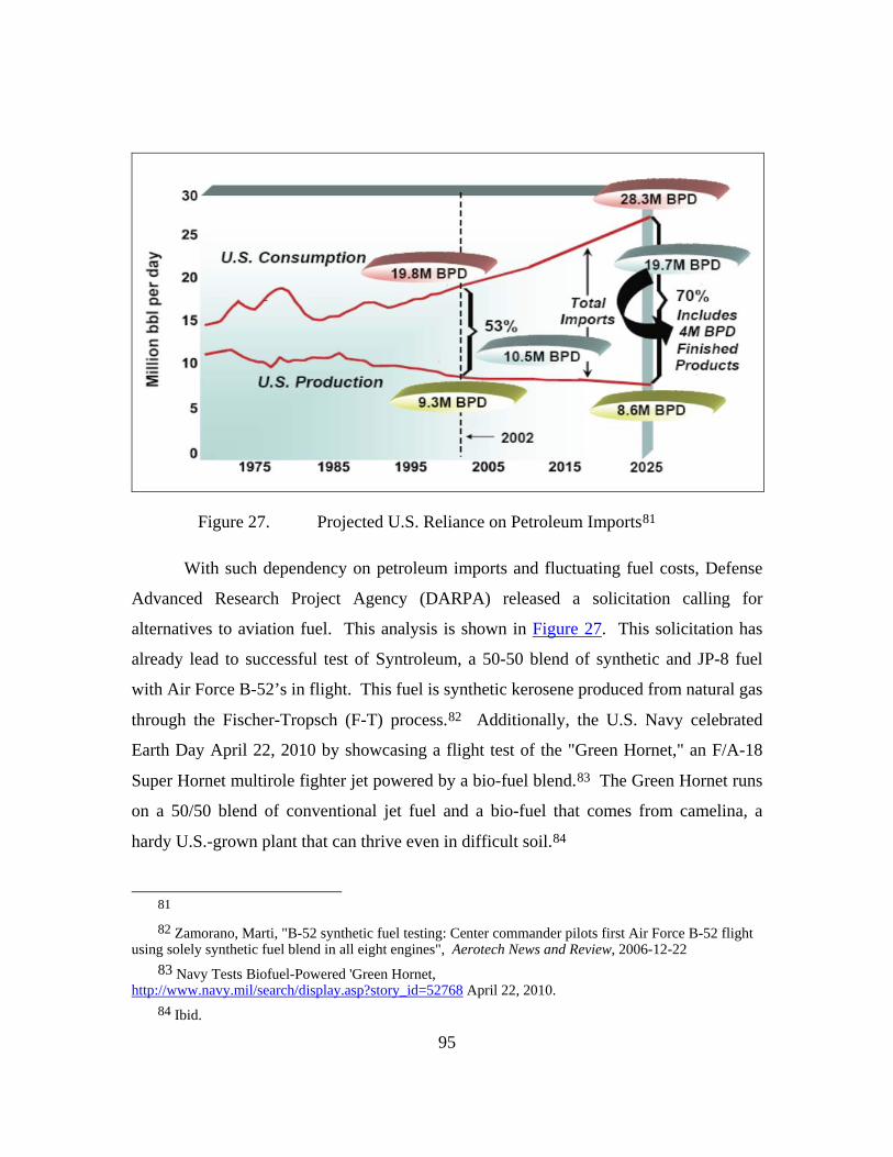
95
Figure 27. Projected U.S. Reliance on Petroleum Imports81
With such dependency on petroleum imports and fluctuating fuel costs, Defense
Advanced Research Project Agency (DARPA) released a solicitation calling for
alternatives to aviation fuel. This analysis is shown in Figure 27. This solicitation has
already lead to successful test of Syntroleum, a 50-50 blend of synthetic and JP-8 fuel
with Air Force B-52’s in flight. This fuel is synthetic kerosene produced from natural gas
through the Fischer-Tropsch (F-T) process.82 Additionally, the U.S. Navy celebrated
Earth Day April 22, 2010 by showcasing a flight test of the "Green Hornet," an F/A-18
Super Hornet multirole fighter jet powered by a bio-fuel blend.83 The Green Hornet runs
on a 50/50 blend of conventional jet fuel and a bio-fuel that comes from camelina, a
hardy U.S.-grown plant that can thrive even in difficult soil.84
81 82 Zamorano, Marti, "B-52 synthetic fuel testing: Center commander pilots first Air Force B-52 flight
using solely synthetic fuel blend in all eight engines", Aerotech News and Review, 2006-12-22 83 Navy Tests Biofuel-Powered 'Green Hornet,
http://www.navy.mil/search/display.asp?story_id=52768 April 22, 2010. 84 Ibid.

96
The use of non-renewable fossil fuels to provide jet fuel should be seen only as a
means to an inevitable end. It is possible that bio-fuel alternatives together with (F-T)
produced synthetic kerosene could offer a potential long-term renewable solution to U.S.
fuel vulnerabilities. Therefore it is only foreseeable that U.S. will be moving towards
bio-fuel in the near future. Table 11 below shows the properties of bio-fuel as compared
to traditional petroleum derived jet fuel:
Fuel
Specific Energy MJ/Kg
Energy Density MJ/I
Boiling Point °C
Freezing Point Viscosity
Jet Fuel 43.2 34.9 150 - 300 <-40 1.2Biodiesel 38.9 33.9 >400 0 4.7Ethanol 27.2 21.6 78 -183 1.52Butanol 36.0 29.2 118 -89 3.64
TABLE 11. BIO-FUEL TO JET FUEL COMPARISON.
As seen in Table 11, using bio-fuel there will yield a significant drop in energy
content as compared to distillate jet fuels currently in use. Thus, there is a high
possibility that fuel alone will not be the sole factor that can be used to improve
endurance for Unmanned Vehicles.

97
3.6.3.3. Future of Fuel Technology
Figure 28. Prediction of Energy Content of Future Fuel
Advanced fuel technology offers the best application for increased
performance in the arena of synthetically derived fuels. One such currently being
explored, High Energy Density Material (HEDM) is a material that might be used as the
fuel for the future. Due to its high energy numbers, Cubane is 71% higher in terms of
Net Heat of combustion by volume, which makes it a good candidate for improving
endurance for Unmanned Vehicles. At the moment, Cubane is not only expensive to
synthesize, but is also extremely time consuming for a material expected to be used in
large quantities. The results are shown in Figure 28.
3.6.4. Battery Technology
3.6.4.1. Current Battery Technology
Throughout the last decade batteries have evolved to power electric
vehicles. The demand for cleaner fuel, longer endurance and minimal cost has caused this
field of research and development to grow at an exponential rate. The three major battery
technologies leading this field are Lead-acid, Nickel Metal Hydride (Ni-MH) and

98
Lithium-ion Battery. Research in the field of Lead acid batteries is nearing an end due to
their large size and reputation of being environmentally unfriendly. See Table 12 below,
for comparison among the three battery technologies85.
Lithium-ion Batteries has become the way of the future because of its high
energy density and long life cycle. Further research and development into Lithium-Ion
batteries will be discussed later.
TABLE 12. BATTERY TECHNOLOGY COMPARISON. 86
3.6.4.2. Lithium-Ion
As noticed in the above chart it is clear why Lithium-Ion batteries and its
research are in the forefront for future use in electric and hybrid technology. As seen in
the chart, lithium batteries have a higher energy density, higher working voltage and life
cycle than that of Ni-MH and lead-acid batteries.
However, the true selling point of Lithium-Ion lies in its more practical
advantages87:
85 General Electric, http://ge.geglobalresearch.com/ 86 Ibid 87 Ibid
99
Efficiently fit most devices due to various shapes and sizes.
Lighter weight.
Power transferred at a lower rate of current.
No memory effect.
Self-discharge rate of approximately 5-10% per month.
3.6.4.3. Lithium Iron Phosphate LiFePO4
Lithium Iron Phosphate is a variation in the chemistry of lithium ion
batteries. General electric Battery company research and development teams have done
various field of study into this type of chemistry. They site this chemistry as “becoming
the best-choice materials in commercial Li-ion Batteries for large capacity and high
power applications.”
Advantages of Lithium Iron Phosphate88:
• Larger capacity compared to other chemistry.
• High power applications
• Safe as lead-acid battery
• Comparable power to lithium ion cells at lower cost.
Disadvantages of Lithium Iron Phosphate89:
• Cost (production of lithium batteries are still very expensive)
• Specific energy (energy/volume) of a new LFP battery is lower
than a new LiCoO2 battery.
• Many brands of LFP's have a low discharge rate compared with
lead-acid or LiCoO2
88 Ibid 89 Lithium Iron Phosphate Batteries ,
http://en.wikipedia.org/wiki/Lithium_iron_phosphate_battery#Advantages_and_disadvantages

100
3.6.4.4. Future Battery Developments
The lithium air battery is an advanced design in which a lithium anode is
electrochemically coupled to atmospheric oxygen through an air cathode. During
discharge, lithium ions flow from the anode through an electrolyte and combine with
oxygen at the cathode (typically consisting of porous carbon) to form lithium oxide Li2O
or lithium peroxide Li2O2, which is inserted in the cathode; this is coupled to the flow of
electrons from the battery's anode to the cathode through a load circuit90. The advantage
of lithium air batteries compared to other technology is the higher density that typical
lithium ions batteries because of the lighter cathode.
Another revolutionary battery concept, the “nanowire battery” was
invented by a team led by Dr. Yi Cui at Stanford University in 2007. It is made up of a
stainless steel anode covered in silicon nanowires, to replace the traditional graphite
anode. Since silicon can store up to ten times more lithium than graphite this allows for a
greater energy density on the anode and reduces the mass of the battery. This battery has
a higher surface area allowing for a faster charging and discharging91
3.6.5. Fuel Cell Technology
The advantage of fuel cell technology is found in its practical operating basis:
converting chemical energy in the fuel into electricity, silently, without explosion or
combustion. Fuel cells have a number of advantages over other technologies for power
generation. They have the potential to use less fuel than competing technologies and
emit no pollution when used. In terms of future applications, fuel cells can provide
power for onboard use (sensors, communication, etc) as well as direct drive propulsion to
physically move the system. There are also many reasons why a fuel cell might be useful
in specific environments, such as the high quality of electricity generated or their quiet
operation.92
90 Lithium Air Battery, http://en.wikipedia.org/wiki/Lithium_air_battery 91 Nanowire Battery, http://en.wikipedia.org/wiki/Nanowire_battery 92 Fuel Cell Today, “General Fuel Cell Information,” http://www.fuelcelltoday.com/ (accessed 05
May, 2010).

101
3.6.5.1. Polymer Electrolyte Membrane
One outstanding example is the German Type 212 Howaldtswerke-
Deutsche Werft (HDW) submarines. These submarines utilize an air-independent
propulsion (AIP) system with polymer electrolyte membrane (PEM) fuel cells developed
by Siemens. These fuel cells enclose a solid polymer electrolyte and yield power outputs
in the range of 30-40 kW.93 On the anodic side of the proton exchange membrane,
hydrogen is decomposed into its protons and electrons. The electrons are then used in the
submarine's power supply. The electrons return via the cathode to re-combine with the
protons, and together with the oxygen molecules in the air form pure water.94
Polymer Electrolyte Membrane fuel cells used in automobiles are called
Proton Exchange Membrane fuel cells. Currently, the car industry is the most promising
industry that is actively investing and researching in PEM technology. The potential
power generated by a fuel cell stack is limited by the number and size of the individual
fuel cells that comprise the stack and the surface area of the PEM. Nevertheless, the
benefits of PEM are as follows:95
• Minimize Emissions. Gasoline- and diesel-powered vehicles emit
greenhouse gases (GHGs), mostly carbon dioxide (CO2), that
contribute to global climate change. However, PEM only by-
product is water.
• Reduced Oil Dependence. Hydrogen can be derived from
domestic sources, such natural gas and coal, as well as renewable
resources such as water. This forms a political and economy
protection by being less dependent on other countries and less
vulnerable to oil price shocks from the volatile oil market.
93 Peter Hauschildt and Albert Hammerschmidt, “PEM Fuel Cells – An Attractive Energy source for
Submarines,” http://info.industry.siemens.com/data/presse/docs/m1-isfb07033403e.pdf (accessed 05 May, 2010).
94 Ibid. 95 Ibid

102
Besides PEM fuel cell, there exist other types of fuel cell technology.
Designs involving an ion-conducting material that range from a liquid alkaline or acid
fixed in a matrix as carrier to molten inorganic salts.
Several other fuel cell designs are compared in Table 29.
Figure 29. Comparison of Fuel Cell Technology
3.6.6. Case Study: UAV application
To better understand what exactly could be gained from studying the
advancements in technologies such as fuel research and development, engine cycle
efficiency, and battery chemistry, an extrapolation of performance parameters for two
UAV platforms was conducted. The MQ-1 Predator and the RQ-4 Global Hawk,
perhaps two of the most publicized UAVs, were analyzed using estimations of increased
engine cycle efficiency and advanced synthetic fuel net heat of combustion estimations.
Table 13 shows the effect engine cycle efficiency alone has on the Predator and
Global Hawk flight characteristics. Assuming the numbers for 2010 are the current
operating specifications, the expected increase in its three key combat parameters can be
mapped out over decade long intervals until 2030:

103
TABLE 13. UAV PERFORMANCE PREDICTION FOR YEAR MILESTONES - ENGINE EFFICIENCY ONLY.
Table 14 shows the added effect of increased net heat of combustion (by weight)
in addition to engine cycle efficiency increases shown from Table 13 above:
TABLE 14. UAV PERFORMANCE PREDICTION FOR YEAR MILESTONES - ENGINE AND FUEL EFFICIENCY.
The combined increase displayed is 22%. This is a fairly conservative 15%
increase in engine efficiency plus a 7% increase in net heat of combustion (by weight).
The two tables above can be seen graphically below in Figure 30.
Radius (nm) Coverage Area (nm2) Endurance (hours)
(Current)
2010 2020 2030 (Current)
2010 2020 2030 (Current)
2010 2020 2030 RQ-4 Global
Hawk 5400 5940 6210 9.16E+07 1.11E+08 1.21E+08 36 39.6 41.4 MQ-1 Predator 500 550 575 7.85E+05 9.50E+05 1.04E+06 40 44 46
Radius (nm) Coverage Area (nm2) Endurance (hours)
(Current)
2010 2020 2030 (Current)
2010 2020 2030 (Current)
2010 2020 2030 RQ-4 Global
Hawk 5400 5940 6588 9.16E+07 1.11E+08 1.36E+08 36 39.6 43.92 MQ-1 Predator 500 550 610 7.85E+05 9.50E+05 1.17E+06 40 44 48.8

104
Figure 30. Endurance Increases by 2030 for the Predator & Global Hawk UAV's
Applying generalized increases in efficiency values and increase in net heat of
combustion (by weight) as direct percentages was assumed valid by implementing the
Breguet Range Equation.
Equation 1: Breguet Range Equation Assuming the velocity of the platform (V), the Earth’s gravitational constant (g),
the platforms lift-to-drag ratio (L/D) and natural log of platform initial and final weights
remain constant, the specific fuel consumption (SFC) can be changed to reflect efficiency
increases.
Increasing Engine Efficiency & Fuel Energy Density

105
3.7. Legal Consideration
A high level assessment of legal considerations was conducted. This section
addressed legal constraints and areas to understand the access of Unmanned Systems to
national and international waterways and airspace.
The Department of Defense Directive (DoDD) requires all DoD activities be fully
compliant with any and all arms control agreements of the U.S. Government.
Additionally DoDD 5000.1 requires that the acquisition and procurement of any DoD
weapons and weapon systems shall be compliant with any and all applicable domestic
law and treaties and international agreements. U.S. Government arms control agreements
relating to unmanned systems (UMS) included the Wassenaar Arrangement (WA), the
Missile Technology Control Regime (MTCR), the Treaty on Conventional Armed Forces
in Europe (CFE), the Vienna Document 1999 (VDOC), Intermediate-Range Nuclear
Forces Treaty (INF), Global Exchange of Military Information (GEMI), and the United
Nations Transparency in Armaments Resolution (UNTIA). Conventional arms
agreements that do not name MS, but include air and ground military vehicles include
CFE, VDOC, INF, GEMI, and UNTIA. WA and MTCR are conventional arms
agreements that directly address UMS.96
3.7.1. International Laws
3.7.1.1. Law of Armed Conflict
“The Law of War” or “Law of Armed Conflict” is the customary and
treaty law applicable to the conduct of warfare on land and the relationships between
belligerents and neutral states. It requires that belligerents refrain from employing any
kind or degree of violence which is unnecessary for military purposes and that they
conduct hostilities with regard for the principles of humanity and chivalry.”97 This in
and of itself poses a level of autonomy which is unachievable with today’s technology.
96 FY2009-2034 Unmanned Systems Integrated Roadmap, Pentagon, Washington, DC, April 2009, p
42. 97 McDaniel, Erin A, “Robot Wars: Legal and Ethical Dilemmas of using Unmanned Robotic Systesm
in 21st Century Warfare and Beyond, “ Fort Leavenworth, Kansas: U.S. Army Command and General Staff College, 2008, p 15.

106
The Law of Armed Conflict could limit the applicability of weaponized unmanned
systems in future combat environments and would need to be addressed on the level of
International Law.
The legality of using an autonomous vehicle to kill enemy forces will be a
concept that needs further study. The difficulty with this concept is that will humans
allow the vehicle’s software be the deciding factor on who is an enemy and therefore
should be attacked. An additional question is “Who is responsible when an autonomous
vehicle conducts “murder” (ie kills an innocent person)?”
3.7.1.2. United Nations Convention on the Law of the Sea (UNCLOS)
All US Naval Ships must fully adhere to the UNCLOS or as they are
commonly referred to as the “Rules of the Road”98. Any UMS that is used no matter the
level of autonomy that it possesses must also comply with the “Rules of the Road”. This
means that in addition to the Command and Control required to operate they must also be
programmed to follow the rules of the road. This will be one of the engineering
challenges that must be met for UMS to operate smoothly in the future force structure.
3.7.1.3. International Civil Aviation Organization (ICAO)
At a minimum, Unmanned Air Systems will need to follow International
Civil Aviation Organization rules and regulations. In addition, due to unique restrictions
not seen in manned aviation, further regulation may be put on Unmanned Air Systems
while in International Airspace.
3.7.2. National Sovereignty
The entry of any vessel or aircraft, including Unmanned Systems, into the
territorial seas or airspace of any country would need prior consent by that country,
except in reference to Safe Haven, Innocent Passage, or Assistance Entry. The use of
unmanned vehicles in or near territorial waters/airspace will require laws to go beyond
98 COMDTINST M16672.2D, NAVIGATION RULES, available from http://www.navcen.uscg.gov,
accessed 20 January 2010

107
what is currently written. The moral or ethical question of programming machines to
employ lethal force has increasingly become an important element that will require laws
at the international level.
3.7.3. Issues within the United States
Currently, the American Society for Testing and Materials (ASTM) International
Committee F38 was selected by the U.S Federal Aviation Administration (FAA) to
develop industry standards for small Unmanned Systems. These standards will be
essential in allowing small UMS to have filed flight plans and to fly missions within the
national airspace in conjunction with manned aircraft.99 Additionally, these standards
would be a stepping stone in allowing larger UMS the authorization to fly within current
FAA controlled airspace.
Any Unmanned Surface Vehicle must integrate within the Coast Guard
International Regulations for Avoiding Collisions at Sea (COLREGS), also known as the
“Marine Rules of the Road”. Besides additional regulations specifically geared towards
Unmanned Systems the vehicles must use high levels of autonomous guidance,
navigation and control systems that provide advanced collision avoidance software.
99 ASTM International, “ASTM to Develop Small Unmanned Air Vehicle Systems Standards for
FAA”, available from http://engineers.ihs.com/news/2010/astm-unmanned-air-vehicle-systems-030110.htm, accessed May 16, 2010.

108
THIS PAGE INTENTIONALLY LEFT BLANK

109
4.0. SYSTEM ANALYSIS
4.1. FUNCTIONAL ARCHITECTURE
4.1.1. Functional architecture Development
4.1.1.1. Functional Architecture Description
The functional architecture for the SEA-16 Integrated Project contains a
hierarchical model of the functions performed by the system, functional flow block
diagrams, and diagrams showing the flow of inputs to and outputs from the functions.
The functional architecture also contains the Measures of Effectiveness (MOEs) which
measure the outputs of the system functions.
Before the functional architectural products are shown, some basic
definitions will be given to clarify what is being described. The first item described is the
definition of a system’s functions. Dennis Buede defines and describes the nature of a
system’s functions below:
A function is an activity or task that the system performs to
transform some inputs into outputs. Every function has activation
and exit criteria. The activation criterion is associated with the
availability of the physical resources, not necessarily with the start
of the transformation activity. The function is activated as soon as
the resource for carrying out the function is available. When the
appropriate triggering input arrives, the function is then ready to
receive the input and begin the transformation process. The
activation criterion for the function then is the combination of the
availability of the physical resource and the arrival of the
triggering input. The exit criterion of a function determines when
the function has completed its transformation tasks.100
100 Buede, Dennis, M, The Engineering Design of Systems ( New York: John Wiley & Sons, Inc.,
2000), 178.
110
Buede’s definition emphasizes that a function describes the action taken
by the system to transform an input to an output. The input could be information,
material resources, electromagnetic signals, energy, or other resources that must be acted
upon by an element in the system. The transformation of the resource results in an output
that is useful to either another physical element of the system or to an external
stakeholder. The usefulness of the output are classified and measured using MOEs.
A functional hierarchy or decomposition is a representation of a how a
function is broken down into its sub functions. The functional hierarchy created was a
structured top down beginning with the top level function, Manage UV Operations, and
decomposing level by level to the lowest level functions. The functions are decomposed
in as much detail as required but not all functions are decomposed to the same level of
detail.
Buede states that functional flow block diagrams (FFBDs), “provide a
hierarchical decomposition of the system’s functions and show a show a control structure
that dictates the order in which the functions can be executed at each level of the
decomposition.”101 Some important details portrayed in the FFBDs are whether
functions are executed in series or parallel, and whether they are completed once or
multiple times before meeting exit criteria. Throughout the FFBDs, the system is
described in a fully operational mode.
A critical component of the success of the functional hierarchy is the
conservation of all the inputs to and outputs from the top level function.102 Conservation
of inputs and outputs means that all inputs to the decomposition are utilized by the
system and are consumed by a transformative activity.
The input/output diagrams detail the inputs to the functions and the
resulting outputs. The diagrams show how the inputs enter the system from the external
101 Buede, Dennis, M, The Engineering Design of Systems ( New York: John Wiley & Sons, Inc.,
2000), 340. 102 Buede Buede, Dennis, M, The Engineering Design of Systems ( New York: John Wiley & Sons,
Inc., 2000), 178.
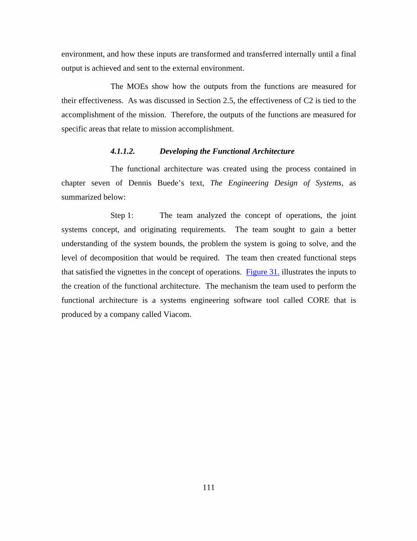
111
environment, and how these inputs are transformed and transferred internally until a final
output is achieved and sent to the external environment.
The MOEs show how the outputs from the functions are measured for
their effectiveness. As was discussed in Section 2.5, the effectiveness of C2 is tied to the
accomplishment of the mission. Therefore, the outputs of the functions are measured for
specific areas that relate to mission accomplishment.
4.1.1.2. Developing the Functional Architecture
The functional architecture was created using the process contained in
chapter seven of Dennis Buede’s text, The Engineering Design of Systems, as
summarized below:
Step 1: The team analyzed the concept of operations, the joint
systems concept, and originating requirements. The team sought to gain a better
understanding of the system bounds, the problem the system is going to solve, and the
level of decomposition that would be required. The team then created functional steps
that satisfied the vignettes in the concept of operations. Figure 31. illustrates the inputs to
the creation of the functional architecture. The mechanism the team used to perform the
functional architecture is a systems engineering software tool called CORE that is
produced by a company called Viacom.
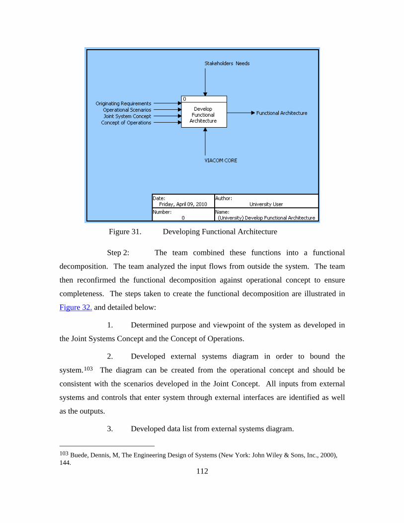
112
Figure 31. Developing Functional Architecture
Step 2: The team combined these functions into a functional
decomposition. The team analyzed the input flows from outside the system. The team
then reconfirmed the functional decomposition against operational concept to ensure
completeness. The steps taken to create the functional decomposition are illustrated in
Figure 32. and detailed below:
1. Determined purpose and viewpoint of the system as developed in
the Joint Systems Concept and the Concept of Operations.
2. Developed external systems diagram in order to bound the
system.103 The diagram can be created from the operational concept and should be
consistent with the scenarios developed in the Joint Concept. All inputs from external
systems and controls that enter system through external interfaces are identified as well
as the outputs.
3. Developed data list from external systems diagram.
103 Buede, Dennis, M, The Engineering Design of Systems (New York: John Wiley & Sons, Inc., 2000), 144.

113
4. Generated activity list.
5. Defined A-O diagram and the level 1 functional decomposition.104
6. Continue process decomposition to levels 1, 2, 3, and 4, as
applicable.
Figure 32. Decomposition Process
Step 3: Address data or item that serve as inputs or outputs to
functions of the functional architecture. Coordinate item flow with the work being
conducted by the C2 architecture task force.
Step 4: Develop MOEs to determine the effectiveness of each
function.
Step 5: Show the functional architecture at a Steering Committee
meeting in order to receive feedback and suggestions for improvement.
4.1.2. Functional Architecture Overview and Summary
4.1.2.1. Description
This architecture is for the command and control of unmanned vehicles in year
2030, including the interface between unmanned vehicles operating in all domains (air,
undersea, surface, land, and space), C2 nodes, other operational units, and external
systems. The principal exchange of information is through a collaborative network
which acts a data fusion network that is distributed across the forces.
4.1.2.2. Purpose and Scope
The purpose of this architecture is to describe the integration of unmanned
and manned vehicles in all domains into a collaborative knowledge sharing environment,
104 Buede, Dennis, M, The Engineering Design of Systems (New York: John Wiley & Sons, Inc., 2000), 66.

114
allowing for unity of effort amongst all the warfare tools in the battlespace. The
architecture is focused toward unmanned vehicles, but takes into account the integration
of manned vehicles through the collaborative network. Knowledge sharing via the
collaborative network is a principle way that manned and unmanned vehicles are
integrated.
The internal aspects of the system include the C2 assets, unmanned
vehicles, manned vehicles, communication equipment, and the collaborative network.
External to the system is the operational environment, threats, other coalition partners,
local populations, higher command centers, and other elements not contained in the
system.
4.1.2.3. Mission
The primary mission that the functional architecture accomplishes is C2.
C2 is the exercise of authority and direction by a properly designated commander over
assigned and attached forces in the accomplishment of the mission. C2 functions are
performed through an arrangement of personnel, equipment, communications, facilities,
and procedures employed by a commander in planning, directing, coordinating, and
controlling forces and operations in the accomplishment of the mission.105
4.1.3. Functional Description
4.1.3.1. Manage UV Operations
The top level function, Manage UV Operations, includes the operation of
unmanned vehicles, the command and control of the unmanned vehicles, and the
collaborative communication and interface between system nodes. The function is
described showing various figures and tables to show the hierarchy, functional flow, and
input/outputs. Figure 33. shows the hierarchy relationship of these functions and Figure
34. shows the functional flow of these functions. Figures 35. and Figure 36. show the
inputs to and the outputs from the top level function.
105 U.S. Department of Defense, Joint Publication 1-02, DOD Dictionary of Military and Associated
Terms, October 2009.

115
Figure 33. shows how the top level function is decomposed to the first
level. Manage UV operations includes the operation of unmanned vehicles, the
command and control of the unmanned vehicles, and the communication and interface
between architecture nodes. Provide C2 is the means and methods by which a
commander recognizes what needs to be done in any given situation and sees that the
appropriate actions are taken. Collaboration is the communication and knowledge
sharing between operational nodes in order to increase each node's understanding of the
current operational situation. Operate UVs is the performance of operational activities by
UVs in the ballet space. Activities include sensor operation, communication, and task
execution.
Figure 33. Manage UV Operations Hierarchy Diagram
The overall intent of the architecture is to manage unmanned vehicle
operations in the 2030 battlespace. In order to achieve the overall management of UV
operations in the 2030 battlespace, the architecture enables the C2 of unmanned vehicles
operating in an environment. The function Collaborate allows knowledge sharing
amongst UVs, manned vehicles, other interested entities such as coalition partners.

116
Figure 34. illustrates the functional flow of the functions which
decompose the top level function Manage UV Operations. Conduct UV Operations,
Collaborate, and Provide C2. The parallel structure indicates that the functions occur
concurrently. While the architecture is in the operational mode, the functions occur in a
continuous loop. Through the collaboration between UVs, manned vehicles, C2 nodes,
and other external agencies, the architecture allows the C2 of operational UVs that are
conducting missions such as surveillance and force protection.
Ref. LP AND
3
Conduct UVOperations
2
Collaborate
1
Provide C2
AND LP Ref.
Date:Thursday, April 08, 2010
Author:University User
Number:0
Name:(University) Manage UV Operations
Figure 34. Manage UV Operations FFBD
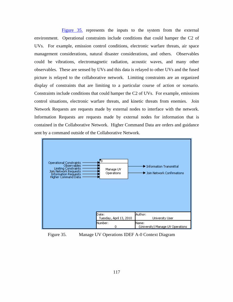
117
Figure 35. represents the inputs to the system from the external
environment. Operational constraints include conditions that could hamper the C2 of
UVs. For example, emission control conditions, electronic warfare threats, air space
management considerations, natural disaster considerations, and others. Observables
could be vibrations, electromagnetic radiation, acoustic waves, and many other
observables. These are sensed by UVs and this data is relayed to other UVs and the fused
picture is relayed to the collaborative network. Limiting constraints are an organized
display of constraints that are limiting to a particular course of action or scenario.
Constraints include conditions that could hamper the C2 of UVs. For example, emissions
control situations, electronic warfare threats, and kinetic threats from enemies. Join
Network Requests are requests made by external nodes to interface with the network.
Information Requests are requests made by external nodes for information that is
contained in the Collaborative Network. Higher Command Data are orders and guidance
sent by a command outside of the Collaborative Network.
Figure 35. Manage UV Operations IDEF A-0 Context Diagram

118
The inputs are received by the system and transformed as shown in Figure
36. The outputs that result are Information Transmittals and Join Network
Confirmations. Information Transmittals are the transmittals of information that was
requested of the network. Joint Network Confirmations are the confirmations sent to
external nodes by the Collaborative Network indicating that the request to join the
network has been confirmed, thus establishing a network connection.

119
Figure 36. Manage UV Operations Input/Output Diagram
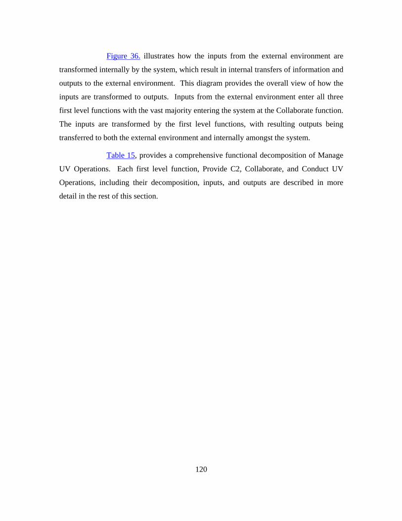
120
Figure 36. illustrates how the inputs from the external environment are
transformed internally by the system, which result in internal transfers of information and
outputs to the external environment. This diagram provides the overall view of how the
inputs are transformed to outputs. Inputs from the external environment enter all three
first level functions with the vast majority entering the system at the Collaborate function.
The inputs are transformed by the first level functions, with resulting outputs being
transferred to both the external environment and internally amongst the system.
Table 15, provides a comprehensive functional decomposition of Manage
UV Operations. Each first level function, Provide C2, Collaborate, and Conduct UV
Operations, including their decomposition, inputs, and outputs are described in more
detail in the rest of this section.

121
TABLE 15. MANAGE UV OPERATIONS HIERARCHY.

122
Table 16 contains a list of all the functions and information items and their
associated definitions. The definitions are as close to the definitions found in Joint
Publication 1-02 with tailoring where appropriate. These definitions assist the
understanding of the functional and input/output descriptions for Manage UV Operations
and its subordinate functions.

123
Element Definition Function
0 Manage UV Operations
This function includes the operation of unmanned vehicles, the command and control of the unmanned vehicles, and the communication and interface between architecture nodes.
1 Provide C2 The means and methods by which a commander recognizes what needs to be done in any given situation and sees that the appropriate actions are taken. It subsumes the process of building situational awareness. Intelligence, surveillance, and reconnaissance activities thus support command and control. Command and control likewise encompasses combat direction, the real-time management of weapons systems. Command is the exercise of authority and control is the information returning to the commander about the results of the action taken - which informs subsequent command action. The commander decides what needs to be done and directs the actions of others. Feedback reveals the difference between intended outcomes and the situation as it actually develops. Feedback thus allows the commander to adapt to changing circumstances. Control is a state the entire system achieves based on feedback about the developing situation.
1.1 Observe To watch the operational situation carefully taking into account details of a situation. The main goal of this function is to be able to process enough information to make sound judgments regarding an operational situation.
1.1.1 Monitor System
To obtain information on the mission, enemy forces, neutral/non-combatants, friendly forces, terrain, and weather.
1.1.1.1 Monitor Internal Factors
Identifying and considering force readiness, including assets available, asset operational status, communication status, and resource requirements.
1.1.1.2 Monitor External Factors
Identifying and considering elements external to the system. Examples include weather factors, enemy activities, limits on electromagnetic radiation, and guidance from higher commands.
1.2 Orient To acquaint with the current situation and environment. The goal of the function Orient is to compare mission criteria to the current situation and identify ways to ensure the mission is being accomplished.
1.2.1 Understand Situation
To acquaint with the current situation and environment.
1.2.1.1 Assess Friendly Capability
Identify the capabilities that the friendly forces can employ in a situation. For example, are there enough UVs to conduct effective surveillance of an operational area?
1.2.1.2 Assess Threat
Given contacts and engageable tracks, classify, type, identify, and evaluate the threat posed to friendly assets and areas.

124
1.2.1.3 Analyze Environment
Take into account the physical environment and the effects on the UV missions. For example, barometric pressure, temperature, humidity, visibility, salinity of water, and wind.
1.2.2 Identify Mission Success Gap
Identify gap between the desired state and the current situation. This could also involve measuring the gap between enemy capability and friendly capability.
1.3 Decide To make a final choice on a course of action (COA). 1.3.1 Determine COAs
The function of choosing a COA. This function includes the process of choosing a COA.
1.3.1.1 Develop COAs
Develop a couple of alternative solutions to the impending problem.
1.3.1.2 Analyze COAs
Taking the nominative COAs and weighing these COAs against the criteria of risk and timing.
1.3.1.2.1 Assess Risk
Analyze the COAs and compare against possible enemy courses of actions. Take into account mission criteria, limitations, and time criticality.
1.3.1.2.2 Analyze Timing
Understand how fast a decision and action must be rendered. Less time critical events allow more analysis where time critical events require very rapid decision making and subsequent action.
1.3.1.2 Select COA
Determine courses of action that best meets mission objectives, while minimizing risk when appropriate.
1.4 Act The decision maker puts the decision into action, which may involve disseminating the decision to others for execution, supervising that execution, and monitoring results through feedback. The Collaborative Network concept envisions that immediate dissemination of dynamic plans across the entire network, to any node or echelon desired. These plans would update automatically in real time, decreasing the need to publish changes and eliminating the time required to do it.
1.4.1 Command Assets
Command is the exercise of authority, including assigning missions, directing UVs, and providing resources.
1.4.1.1 Assign Mission
After an analysis and decision are rendered, the system must be able to process the decision and give mission tasking to required assets.
1.4.1.2 Direct UVs
Unmanned vehicles must be directed as required given UV level of autonomy. The level of autonomy of the UV will vary given the particular mission and

125
environment; thus the system must be able to direct UVs in low to high autonomy situations.
1.4.1.3 Provide Resources
Provide required assets, fuel, and support as dictated by the operational environment, friendly capability, and time criticality.
1.5 Share to Network
The passing of C2 Node information to the Collaborative Network in order to enhance collaboration.
2 Collaborate To communicate and share knowledge with other operational nodes in order to increase each node's understanding of the current operational situation.
2.1 Operate in Network
The ability to exploit all human and technical elements of the force and its mission partners by fully integrating collected information, experience, knowledge, and decision making via a collaborative network. Data and information are securely shared via the network, enhancing each individual node's awareness. The network will connect all nodes including UVs that condu ct operations, manned assets and C2 nodes that provide the Command and Control to operational assets. The goal is a seamless integration between manned and unmanned assets across all domains with the appropriate C2 node.
2.1.1 Establish Capability Interface
Establish Capability Interface is the sharing of needed operational information when information is entered via a user capability interface or through a sensor transduction capability interface.
2.2 Manage Data Given information, ensure decision makers have ready access to the information they want and need while minimizing the risk of information overload.
2.2.1 Organize Data
The filtering, prioritizing, and manipulating to present observable reports. The goal is to present information to C2 nodes that is useful and manageable, not overwhelming.
2.2.2 Share Data Operational nodes must be able upload information to a Collaborative Network in order to increase each internal operational node's understanding of the situation and also to inform external stakeholders that interface with the network.
2.3 Collect Data The system must be able to receive information from external stakeholders, such as unmanned vehicles, targets, and external agencies.
2.4 Secure Network
Information in the operational nodes and network must protect information from information attacks carried out by hackers and enemies.
3 Conduct UV Operations
Carrying out operational missions via unmanned vehicles. Missions could include force protection and reconnaissance missions. This set of functions will focus on the functions that allow the navigation and task completion by UVs, as well as the communication to and from the collaborative network and the C2 nodes.
3.1 Operate Sensors
The utilization of sensors onboard UVs, such as optical, IR, acoustic, weather reading, RADAR, temperature, CBR, and other sensors that are utilized by vehicles.
3.1.1 Sense Environment
Identifying, reading, and exploiting of observables in the environment. Observables could be vibrations, electromagnetic radiation, acoustic waves, and

126
many other forms of stimuli.
3.1.2 Share Raw Sensor Data
Sending sensor data to other vehicles in the vicinity for greater situational awareness amongst operational nodes. These other vehicles could be other UVs or manned vehicles.
3.1.3 Fuse Sensors
Taking many different sensor feeds and combining them to create a situational picture or sensor picture. For example, an optical target could be correlated to an acoustic or radar target, thereby giving the type of target, and the course and speed of target.
3.1.4 Share Sensor Picture
The sending of the fused sensor picture to the collaborative network and other vehicles.
3.2 Operate UVs The performance of operational activities by UVs in the battlespace. Activities include navigation, planning, task execution, and reporting.
3.2.1 Formulate Tactics
Utilizing the artificial intelligence capabilities of UVs, the sensor picture from UVs, and inputs from C2 nodes, a tactical plan is formulated. The tactical plan includes maneuver information, sensor usage, weapon usage, and other relevant tactical tasks for a given situation.
3.2.2 Schedule and Allocate Tasks
Given a tactical plan, the determination of specific tasks required to accomplish the plan. The tasks are scheduled and allocated to different assets.
3.2.3 Navigate and Execute Tasks
Maneuver in a given environment and the carrying out of tasks.
3.2.4 Report Position Status
Provide the collaborative network and required operational assets updates on position and the status of the task completion. This provides situational awareness to the nodes in the network.
3.2.5 Assess/Report Operational Availability
Identify elements of the UVs and required equipment that may hinder the operational availability of the required assets.
Input/Output Items Join Network Requests
Requests made by external nodes to interface with the network.
Information Requests
Requests made by external nodes for information that is contained in the Collaborative Network.
Join Network Confirmations
The confirmation sent to the external node by the Collaborative Network indicating that the request to join the network has been confirmed, thus establishing a network connection.
Information Transmittal
The sending of information that was requested of the network.
UV Status The data detailing where a UV is operating, where it can be available to operate,

127
/Location and where it is in terms of tasking completion. Resources Available
Data specifying resources available for UV operations. For example, how much fuel is available to sustain UVs for a particular operation? How many reserve UVs are available given casualties to UVs in the AO?
Higher Command Data
Orders and guidance sent by a command outside of the Collaborative Network.
Operational Constraints
Operational constraints include conditions that could hamper the C2 of UVs. For example, emission control conditions, electronic warfare threats, air space management considerations, natural disaster considerations, and others.
Communication Errors
Failures in the communications between nodes in the system. For example, this data would indicate a loss of communications to a UV.
Collected Data Data that is received by a node in the C2 network. Secured Data Data that has been secured by the network. Organized Data Organized Data is the data which has been filtered, prioritized, and manipulated
into an observable and understandable form. UV Control Data (Telemetry)
Automatic measurement and transmission of unmanned vehicle data by wire, radio, or other means from remote sources, as from unmanned aerial vehicles, to receiving stations for recording, analysis, and control purposes.
Asset Availability An organized report specifying which UV's and other assets such as manned vehicles are available for specific mission.
Communication Status
An organized report specifying whether or not a UV or other communication asset has positive communication.
Environmental Report
An organized report displaying data input to the Collaborative Network that specifies environmental parameters such as temperature, barometric pressure, wind speed, and level of humidity.
Friendly Force Report
An organized report specifying the operational capability of the forces assigned to a particular commander. This report can specify different levels of force readiness, such as forces available for a specific tactical engagement or an operational campaign.
Higher Command Guidance
Direction and orders input to the network from higher commands that alter the C2 of the sy stems.
Limiting Constraints
An organized display of limitations to a particular course of action or operational configuration. Constraints include conditions that could hamper the C2 of UVs. For example, emissions control situations, electronic warfare threats, and kinetic threats from enemies.
Threat Report An organized display of the threat or enemy. The report details the nature of the threat such as the platform type, number of enemy forces, weapon system characteristics, any hostile actions, and tracking, targeting information.

128
Resource Requirements
An organized display of the resources required by internal nodes of the system.
Observed Reports Reports that have been filtered by the network in the Manage Data function and are now observed in a manner that facilitates comprehension in the least amount of time possible.
Force Picture The Force Picture assimilates the Observed Friendly Force Report, Observed Higher Command Guidance, Observed Limiting Constraints, Observed Asset Availability, Observed Resource Requirements, and Observed Communication Status. The Force Picture provides the situation in a manner that allows follow-on decision making.
Environmental Picture
A representation of the environmental situation, including parameters such as temperature, barometric pressure, wind speed, level of humidity, in a manner that allows follow on decision making. (barometric pressure, wind speed, and level of humidity)
Threat Picture A representation of the threat that allows follow on decision making. Mission Gap Picture
The mission gap picture is the result of the Force Picture, Threat Picture, and Environmental Picture. The threat is compared against the friendly forces in a given environment. The result is the indication of whether what is expected to be happening is actually occurring. This is a key element of the Control aspect of C2.
COAs COAs that the commander developed to meet mission objectives. A couple of feasible options are generally generated in order to decide which option is best through analysis
Analyzed COAs COAs that have been assessed and analyzed for their time criticality. Selected COA The selected COA is the COA that the decision maker has chosen after weighing
factors such as the gap between the desired state and the actual state, risk, and timing factors.
Mission Tasking Mission tasking is direction specifying the selected course of action and associated orders to a particular node.
Resource Orders Required assets, fuel, and support as dictated by the operational environment, friendly capability, and time criticality.
UV Control Orders
UV control orders are orders given by the C2 node indicating a particular action to be taken by a UV. The level of control data will vary from a mission update to an autonomous UV to more consistent stream of control orders to less autonomous UVs.
Observables Observables could be vibrations, electromagnetic radiation, acoustic waves, and many other observables. These are sensed by UVs and this data is relayed to
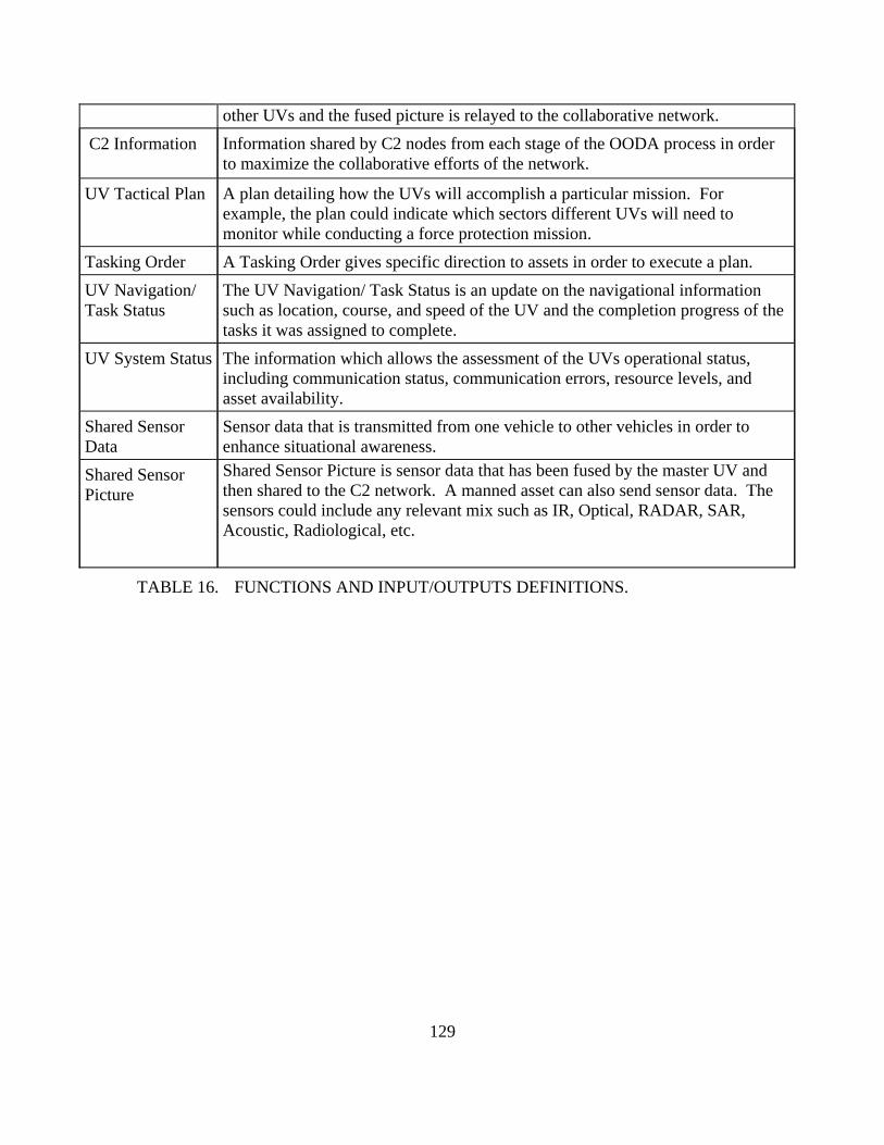
129
TABLE 16. FUNCTIONS AND INPUT/OUTPUTS DEFINITIONS.
other UVs and the fused picture is relayed to the collaborative network. C2 Information Information shared by C2 nodes from each stage of the OODA process in order
to maximize the collaborative efforts of the network.
UV Tactical Plan A plan detailing how the UVs will accomplish a particular mission. For example, the plan could indicate which sectors different UVs will need to monitor while conducting a force protection mission.
Tasking Order A Tasking Order gives specific direction to assets in order to execute a plan. UV Navigation/ Task Status
The UV Navigation/ Task Status is an update on the navigational information such as location, course, and speed of the UV and the completion progress of the tasks it was assigned to complete.
UV System Status The information which allows the assessment of the UVs operational status, including communication status, communication errors, resource levels, and asset availability.
Shared Sensor Data
Sensor data that is transmitted from one vehicle to other vehicles in order to enhance situational awareness.
Shared Sensor Picture
Shared Sensor Picture is sensor data that has been fused by the master UV and then shared to the C2 network. A manned asset can also send sensor data. The sensors could include any relevant mix such as IR, Optical, RADAR, SAR, Acoustic, Radiological, etc.
130
4.1.3.2. Provide C2
Provide C2 is the function which commands and controls the operational
UVs. The model chosen to describe C2 is a modified Boyd’s’ OODA loop as discussed
in Section 3.1. C2 is defined as the means and methods by which the appropriate actions
are taken. Feedback reveals the difference between intended outcomes and the situation
as it develops. Feedback thus allows the system elements to adapt to changing
circumstances. Control is a state the entire system achieves based on feedback about the
developing situation.106
The architecture products for Provide C2 are shown below in the same
sequence as Manage UV Operations. Figure 37. shows the hierarchy, Figure 38. shows
the functional flow. Table 17 and Figures 39. through Figure 46. show the input/output
of each function.
106 U.S. Department of Defense, Joint Publication 1-02, DOD Dictionary of Military and Associated
Terms, October 2009.

131
Figure 37. Provide C2 Hierarchy Diagram

132
Figure 37. is the functional decomposition of Provide C2. Provide C2 is
described using the Observe, Orient, Decide, Act, of Boyd’s OODA loop with the
addition of Share to Network. The black squares located on the upper left hand corner of
the level three functions indicate that the level three functions are broken down to a
further level as shown in Table 17. The next several paragraphs detail the hierarchy of
Provide C2 by defining each function and explaining the functional decomposition.
Observe entails watching the operational situation carefully taking into
account details of a situation. The main goal of this process is to be able to handle
enough information to make sound judgments regarding an operational situation.
Observe is decomposed by Monitor the Situation. Monitor the Situation allows the
commander to obtain information on the mission, enemy forces, neutral/non-combatants,
friendly forces, terrain, and weather. Monitor the Situation is decomposed by Monitor
Internal Factors and Monitor External Factors. Monitoring Internal Factors involves
identifying and considering force readiness, including assets available, asset operational
status, communication status, and resource requirements. Monitoring External Factors
involves identifying and considering elements external to the system. Examples include
weather factors, enemy activities, limits on electromagnetic radiation, and guidance from
higher commands.
Orient allows the commander to acquaint with the current situation and
environment. The goal of Orient is to compare mission criteria to the current situation
and identify ways to ensure the mission is being accomplished. Orient is decomposed by
Understand the Situation and Identify Mission Success Gap.
Understand the Situation involves becoming familiar with the current
situation and environment. Understand the Situation is decomposed by Assess Friendly
Capability, Assess Threat, and Analyze Environment. Assess Friendly Capability is the
identification of the capabilities that the friendly forces can employ in a situation. For
example, are there enough UVs to conduct effective surveillance of an operational area?
Assess Threat involves the identification, classification, and evaluation of a threat posed
to friendly assets and areas. Analyze Environment takes into account the physical
133
environment and the effects on the UV missions, for example, barometric pressure,
temperature, humidity, visibility, salinity of water, and wind.
Identify Mission Success Gap identifies the gap between the desired state
and the current situation.
Decide is to make a final choice on a course of action (COA). Decide is
decomposed into Determine COA. Determine COA includes the actions involved in
choosing a COA. Determine COAs is decomposed into Develop COAs and Analyze
COAs. Develop COAs involves the development of a couple of alternative solutions to
the impending problem. Analyze COAs involves taking the nominative COAs and
weighing these COAs against the criteria of risk and timing. Analyze COAs is
decomposed further into include Assess Risk, and Analyze Timing, and Select COA.
Assess Risk involves the analysis of COAs with a comparison against possible enemy
courses of action. The analysis takes into account mission criteria and limitations.
Analyze Timing is to understand how fast a decision and action must be rendered. Less
time critical events allow more analysis where time critical events require very rapid
decision making and subsequent action. The final process of Decide is Select COA.
Select COA is to determine COAs that best meets mission objectives, while minimizing
risk when appropriate.
Act is where the decision maker puts the decision into action, which may
involve disseminating the decision to others for execution, supervising that execution,
and monitoring results through feedback. The Collaborative Network concept envisions
the immediate dissemination of dynamic plans across the entire network, to any node or
echelon desired. These plans would update automatically in near real time, decreasing
the need to publish changes and eliminating the time required to do it. Act is
decomposed by Command Assets which is further decomposed into Assign Missions,
Direct UVs, and Provide Resources.
Command Assets is the exercise of authority, including assigning
missions, directing UVs, and providing resources. Command Assets is decomposed to
Assign Mission, Direct UVs, and Provide Resources. Assign Mission is what is done

134
autonomously or by the commander or representative of the commander after an analysis
and decision are rendered, the system must be able to process the decision and give
mission tasking to required assets. Direct UV’s includes the control of UVs. Unmanned
vehicles must be directed as required given UV level of autonomy. The level of
autonomy of the UV will vary given the particular mission and environment; thus the
system must be able to direct UVs in low to high autonomy situations. Provide
Resources is the providing of required assets, fuel, and support as dictated by the
operational environment, friendly capability, and time criticality.
Share to Network is the final sub function of Provide C2. Share to
Network is the passing of C2 node information to the Collaborative Network in order to
enhance collaboration. Sharing information to the network is critical in terms of enabling
effective knowledge sharing and unity of effort amongst operation units in a battlespace.

135
Figure 38. Provide C2 FFBD

136
Figure 38. is the FFBD for Provide C2. The diagram shows that the
functions OODA and Share to Network happen in parallel and in a continuous loop while
the system is in operational mode. The logic for placing the OODA steps in concert with
Share to Network is to enable the sharing of information to the Collaborative Network at
each stage of the OODA loop. For example, in a force protection mission, the
commander receives information from unmanned vehicles that are in the Collaborative
Network. The commander observes a Threat Report and the system communicates that
the report has been observed. The Observed Threat Report is then moved in to the Orient
step where the commander gains an understanding of the situation and determines what
needs to be done. The commander’s assessment from the Orient step is shared to the
Collaborative Network in order to enhance other units’ situational awareness. The same
sharing occurs after a COA is determined in the Decide function. If there is a problem
during in accomplishing the COA during the Act function, such as the C2 node being
destroyed, another unit could assume command of the assets because there is a shared
understanding of the problem.

137
Table 17 provides a tabular representation of the inputs and outputs to
Provide C2. This table will assist the understanding of the subsequent item flow
diagrams.
INPUT FUNCTION OUTPUT UV Control Data Threat Report Resource Requirements Limiting Constraints Higher Command Guidance Friendly Force Report Environmental Report
1 Provide C2
C2 Information Mission Tasking Resource Orders UV Control Order
Threat Report Resource Requirements Limiting Constraints Higher Command Guidance Friendly Force Report Environmental Report
1.1 Observe
Observed Reports consisting of: Observed Threat Report Observed.Resource Requirements Observed Limiting Constraints Observed Higher Command Guidance Observed Friendly Force Report Observed Environmental Report
Threat Report Resource Requirements Limiting Constraints Higher Command Guidance Friendly Force Report Environmental Report
1.1.1 Monitor Situation
Observed Threat Report Observed Resource Requirements Observed Limiting Constraints Observed Higher Command Guidance Observed Friendly Force Report Observed Environmental Report
Resource Requirements Friendly Force Report
1.1.1.1 Monitor Internal Environment
Observed Resource Requirements Observed Friendly Force Report
Threat Report Limiting Constraints Higher Command Guidance Environment Report
1.1.1.2 Monitor External Environment
Observed Threat Report Observed Limiting Constraints Observed Higher Command Guidance Observed Environmental Report
Observed Reports 1.2 Orient Force Picture Mission Gap Picture
Observed Reports 1.2.1 Understand Situation
Environment Picture Force Picture Threat Picture
Observed Resource Requirements Observed Friendly Force Report Observed Limiting Constraints Observed Higher Command Guidance Observed Communication Status Observed Asset Availability
1.2.1.1 Assess Friendly Capability
Force Picture
Observed Threat Report 1.2.1.2 Assess Threat Threat Picture Observed Environmental Report 1.2.1.3 Analyze Environment Environmental Picture Threat Picture 1.2.2 Identify Mission Success Mission Gap Picture

138
TABLE 17. PROVIDE C2 INPUT/OUTPUT.
The next several figures, Figures 39. through Figure 46., depict the
information flows of the sub functions of Provide C2. These diagrams are intended to
present a visual representation with corresponding discussion of the information found in
Table 17.
Figure 39. shows the information flow for the Monitor Situation, which is
a sub function of Observe. Monitor Situation is decomposed by Monitor Internal Factors
and Monitor External Factors. The inputs to Monitor Internal Factors are Friendly Force
Report and Resource Requirements. The Friendly Force Report is an organized report
specifying the operational capability of the forces assigned to a particular commander.
This report can specify different levels of force readiness, such as forces available for a
specific tactical engagement or an operational campaign. Resource Requirements is an
organized display of the resources required by internal nodes of the system.
Force Picture Environment Picture
Gap
Mission Gap Picture 1.3 Decide Selected COA Mission Gap Picture 1.3.1 Determine COA Selected COA Mission Gap Picture 1.3.1.1 Develop COAs COAs COAs 1.3.1.2 Analyze COAs Analyzed COAs Analyzed COAs 1.3.1.2.1 Assess Risk Risk Assessed COAs Risk Assessed COAs 1.3.1.2.2 Analyze Timing Analyzed COAs Analyzed COAs 1.3.1.3 Select COA Selected COA Selected COA UV Control Data (Telemetry) Force Picture
1.4 Act Mission Tasking UV Control Orders Resource Orders
UV Control Data (Telemetry) Selected COA Force Picture
1.4.1 Command Assets UV Control Order Mission Tasking Resource Orders
Selected COA 1.4.1.1 Assign Mission Mission Tasking UV Control Data (Telemetry) 1.4.1.2 Direct UVs UV Control Order Force Picture 1.4.1.3 Provide Resources Resource Orders Selected COA Observed Reports Mission Gap Picture Force Picture Mission Tasking Resource Orders
1.5 Share To Network
C2 Information

139
Figure 39. Monitor System Item Flow
The inputs to Monitor External Requirements are: Environmental Report,
Higher Command Guidance, Limiting Constraints, and Threat Report. The
Environmental Report is an organized report displaying data input to the Collaborative
Network that specifies environmental parameters such as temperature, barometric
pressure, wind speed, and level of humidity. Higher Command Guidance contains orders
and direction input to the network from higher commands that alter the command and
control of the systems. Limiting Constraints are an organized display of limitations to a
particular course of action or operational configuration. Constraints include conditions
that could hamper the C2 of UVs. For example, emissions control situations, electronic
warfare threats, and kinetic threats from enemies. The Threat Report is an organized
display of the threat or enemy. The report details the nature of the threat such as the
platform type, number of enemy forces, weapon system characteristics, any hostile
actions, and tracking, targeting information.
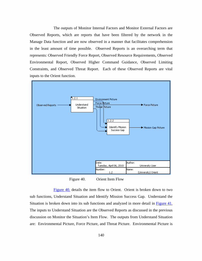
140
The outputs of Monitor Internal Factors and Monitor External Factors are
Observed Reports, which are reports that have been filtered by the network in the
Manage Data function and are now observed in a manner that facilitates comprehension
in the least amount of time possible. Observed Reports is an overarching term that
represents: Observed Friendly Force Report, Observed Resource Requirements, Observed
Environmental Report, Observed Higher Command Guidance, Observed Limiting
Constraints, and Observed Threat Report. Each of these Observed Reports are vital
inputs to the Orient function.
Figure 40. Orient Item Flow
Figure 40. details the item flow to Orient. Orient is broken down to two
sub functions, Understand Situation and Identify Mission Success Gap. Understand the
Situation is broken down into its sub functions and analyzed in more detail in Figure 41.
The inputs to Understand Situation are the Observed Reports as discussed in the previous
discussion on Monitor the Situation’s Item Flow. The outputs from Understand Situation
are: Environmental Picture, Force Picture, and Threat Picture. Environmental Picture is

141
a representation of the environmental situation, including parameters such as temperature,
barometric pressure, wind speed, level of humidity, in a manner that allows follow on
decision making. The Force Picture assimilates the Observed Friendly Force Report,
Observed Higher Command Guidance, Observed Limiting Constraints, Observed Asset
Availability, Observed Resource Requirements, and Observed Communication Status.
The Force Picture provides the situation in a manner that allows follow on decision
making. The Force Picture provides the situation in a manner that allows follow on
decision making. The Force Picture is output to both Identify Mission Success Gap
under the Orient function and to Command Assets under the Act function to assist the
commander in directing forces. The Threat Picture is a representation of the threat that
allows follow on decision making.
The outputs from Understand Situation are inputs to Identify Mission
Success Gap. Identify Mission Success Gap’s output is the Mission Gap Picture. The
Mission Gap Picture is the result of the transformation of the Force Picture, Threat
Picture, and Environmental Picture. The threat is compared against the friendly forces in
a given environment. The desired state is also compared to what is actually occurring in
the battlespace. The result is the indication of whether what is expected to be happening
is actually occurring and is a key element of the Control aspect of C2.

142
Figure 41. Understand Situation Item Flow

143
Figure 41. decomposes Understand Situation into the sub functions:
Assess Friendly Capability, Assess Threat, and Analyze Environment. The inputs to
Assess Friendly Capability are: Observed Friendly Force Report, Observed Limiting
Constraints, Observed Command Guidance, Observed Communication Status, Observed
Asset Availability, Observed Resource Requirements, and Observed Reports. As
discussed in Monitor Situation’s item flow (Figure 39.) discussion, the Observed Reports
are reports that have been transformed in the Observe function. The output from Assess
Friendly Capability is the Friendly Force Picture. The output from Assess Threat is the
Threat Picture. The output from Analyze Environment is the Environmental Picture.
The definitions of each of these outputs were described in Orient’s item flow (Figure 40.)
discussion.

144
Figure 42. shows Decide’s sub function, which is Determine COA.
Determine the COA is further broken down and defined in Figure 43. The input to
Decide is the Mission Gap Picture, which was an output from Orient. The Mission Gap
Picture allows the determination of the COA by showing what areas to focus on. Upon
completing the Decide function, a Selected COA is output from the Decide function. The
Selected COA is the COA that the decision maker has chosen after weighing factors such
as the gap between the desired state and the actual state, risk, and timing factors.
Figure 42. Decide Item Flow
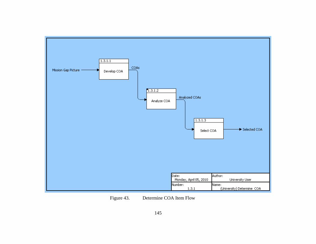
145
Figure 43. Determine COA Item Flow

146
Figure 43. shows the decomposition of Determine COA. Determine COA
is decomposed by: Develop COA, Analyze COA, and Select COA. Figure 44. will
further decompose Analyze COA. The input to Develop COA is the Mission Gap Picture
which was discussed previously in Figure 40.’s discussion. Develop COA outputs are the
different COAs that the commander developed to meet mission objectives. The candidate
COAs are then input to Analyze COA, which takes the nominative COAs and weighing
these COAs against the criteria of risk and timing. The outputs are the Analyzed COAs
which are input to Select COA. In this function, a final COA is chosen which the
commander feels will give the highest probability of success given the limitations and
resources the commander is faced with. The output from Decide is the Selected COA
which is the COA that the decision maker has chosen after weighing factors such as the
gap between the desired state and the actual state, risk, and timing factors.
Figure 44. Analyze COA Item Flow.

147
Figure 44. is the decomposition of function Analyze COA. The inputs to
this function are the candidate COAs which were generated in the Develop COA
function. The COAs are risk assessed where possible enemy courses of action and
reactions are taken into account. Also, such items as mission criteria, limitations, and
time criticality were considered. The resulting outputs are the Risk Assessed COAs
which are then specifically analyzed for timing considerations in the function Analyze
Timing. During Analyze Timing, the commander assesses how fast a decision and action
must be rendered. Less time critical events allow more analysis where time critical
events require very rapid decision making and subsequent action. The resulting outputs
are the Analyzed COAs as discussed in terms of risk and timing analysis in the discussion
on Figure 43.
Figure 45. Act Item Flow

148
Figure 45. shows the item flow for the Act function. Act is decomposed
by the function Command Assets which are decomposed further in Figure 46. The inputs
to Command Assets are: Selected COA, UV Control Data (Telemetry) and the Force
Picture. Selected COA is the chosen COA as discussed in Figure 43.’s discussion. UV
Control Data (Telemetry) is output from UVs operating in the environment and is the
automatic measurement and transmission of unmanned vehicle data by wire, radio, or
other means from remote sources, as from unmanned aerial vehicles, to receiving stations
for recording, analysis, and control purposes. The Force Picture assimilates the observed
friendly force report, observed higher command guidance, observed limiting constraints,
observed asset availability, observed resource requirements, and observed
communication status. The intent of the Force Picture is to enhance the director of the
unmanned vehicles situational awareness.
The outputs from Command Assets are UV Control Orders, Resource
Orders, and Mission Tasking. UV Control Orders are an order given by the C2 network
indicating a particular action to be taken by a UV. The level of control data will vary
from a mission update to an autonomous UV to more consistent stream of control orders
to less autonomous UVs. Resource orders are orders which provide resources operating
assets. An example of a resource order would be to direct a refueling asset to refuel a
UAV or direct another UAV to replace a UAV needing to leave a surveillance post.
Mission Tasking is the issuing of the selected course of action and associated orders to a
particular node. For example, C2 may order a UUV to detonate an identified underwater
mine, or other similar task.
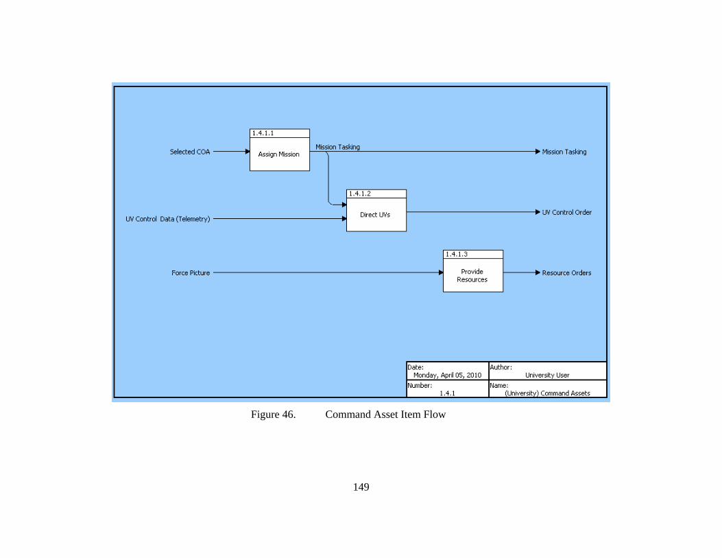
149
Figure 46. Command Asset Item Flow

150
Figure 46. is the decomposition of Command Assets. Command Assets is
broken down into Assign Mission, Direct UVs, and Provide Resources. The definitions
of these sub functions are found in the discussion under Figure 43.’s discussion. The
input and output definitions are the same as discussed under Figure 45.’s discussion.
4.1.3.3. Collaborate
Collaboration is vital to achieving a shared situational awareness. Below
are the architectural products of the function Collaborate. Figure 47. illustrates the
hierarchical structure and Figure 48. depicts the functional flow. Table 18, Figure 49.
and Figure 50. represent the input/output of each function.
Figure 47. Collaborate Hierarchy
Figure 47. is the functional decomposition of Collaborate. Collaborate is
decomposed into four functions: Operate in Network, Manage Data, Collect Data, and
Secure Network.

151
Operate in Network is the ability to exploit all human and technical
elements of the force and its mission partners by fully integrating collected information,
experience, knowledge, and decision making via a collaborative network. 107 Data and
information are securely shared via the network, enhancing each individual node's
awareness. The network will connect all nodes including UVs that conduct operations,
manned assets and C2 nodes that provide the Command and Control to operational assets.
The goal is a seamless integration between manned and unmanned assets across all
domains with the appropriate C2 node. Operate in Network is further broken down to
Establish Capability Interface. Establish Capability Interface is the sharing of needed
operational information when information is entered via a user capability interface or
through a sensor transduction capability interface.
Manage Data ensures, given information, that decision makers have ready
access to the information they want and need while minimizing the risk of information
overload. Manage Data is decomposed into two sub functions: Organize Data and Share
Data. Organize Data is the filtering, prioritizing, and manipulating to present observable
reports. The goal is to present information to C2 nodes that is useful and manageable, not
overwhelming. Share data is the uploading of information to a collaborative network in
order to increase each internal operational node's understanding of the situation and also
to inform external stakeholders that interface with the network.
Collect data is the receiving of information from all necessary internal
system nodes such as UVs, manned vehicles, and C2 centers, as well as required data
from external agencies.
Secure network is the function which ensures information assurance.
Information in the operational nodes and network must be protected from information
attacks by hackers and enemies.
107 U.S. Department of Defense, Joint Publication 1-02, DOD Dictionary of Military and Associated
Terms, October 2009.

152
Ref.
3
Conduct UVOperations
2
Collaborate
1
Provide C2
AND
OR AND
2.1
Operate in Network AND
2.3
Collect Data
2.2
Manage Data
AND
2.4
Secure Network
AND OR
Ref.
AND
3
Conduct UVOperations
2
Collaborate
1
Provide C2
Date:Thursday, April 08, 2010
Author:University User
Number:2
Name:(University) Collaborate
Figure 48. Collaborate FFBD

153
Figure 48. is the FFBD for Collaborate. The figure illustrates that Operate
in Network occurs concurrently with Secure Network. The network must be secured at
all times while the system is in operation. The figure also shows that Collect Data and
Manage Data occur in parallel. The system must be able to receive data and filter data at
the same time.

154
Table 18 provides a tabular representation of the inputs to and outputs
from Collaborate. This table will assist the understanding of the subsequent item flow
diagrams.
TABLE 18. COLLABORATE INPUT/OUTPUT.
INPUT FUNCTION OUTPUT Join Network Requests Information Requests UV Status/Location Resources Available Higher Command Data Operational Constraints Communication Errors Asset Availability Communication Status C2 Information Shared Sensor Picture
2 Collaborate
Join Network Confirmations Information Transmittal Environmental Report Friendly Force Report Higher Command Guidance Limiting Constraints Threat Report Resource Requirements
Join Network Requests 2.1 Operate In Network Join Network Confirmations
Join Network Requests 2.1.1 Establish Capability Interface Join Network Confirmations
Secured Data Information Requests
2.2 Manage Data
Environmental Reports Friendly Force Report Higher Command Data Information Transmittal Limiting Constraints Resource Requirements Threat Report
Secured Data 2.2.1 Organize Data Organized Data Organized Data Information Requests
2.2.2 Share Data
Environmental Reports Friendly Force Report Higher Command Guidance Informational Transmittal Limiting Constraints Resource Requirements Threat Report
UV Status Shared Sensor Picture Resources Available Operational Constraints Higher Command Data Communication Status Communication Errors C2 Information Asset Availability
2.3 Collect Data
Collected Data
Collected Data 2.4 Secure Network Secured Data

155
Higher Command Guidance
Higher Command Data
Friendly Force ReportEnvironmental Report
Communication StatusCommunication Errors
Collected DataC2 Information
Asset AvailabilityUV Stat...
Threat Report
Shared Sensor Picture
Secured Data
Resources Available
Resource Requirements
Operational Constraints
Limiting Constraints
Join Network Requests Join Network Confirmations
Information Transmittal
Information Requests
2.1
Operate in Network
2.3
Collect Data
2.2
Manage Data
2.4
Secure Network
Date:Thursday, April 08, 2010
Author:University User
Number:2
Name:(University) Collaborate
Figure 49. Collaborate Item Flow

156
Figure 49. displays the item flow for the Collaborate function. The first
point of discussion are the two inputs that do not go directly to collect data. Join
Network Requests are requests made by external nodes to interface with the network. The
requests are processed in the function Operate in Network through the sub function
Establish Capability Interface. If the request is verified and approved, the function
outputs Join Network Confirmations. Information Requests are specific requests by
entities that have established an interface for information contained in the network. The
request is processed by the Manage Data function where the request is processed and a
request is sent via the output Information Transmittal.
The majority of the inputs to the system flow into the Collect Data
function. The inputs to Collect Data are: Operational Constraints, Resources Available,
Shared Sensor Picture, UV Status/Location, Asset Availability, C2 Information,
Communication Errors, Communication Status, and Higher Command Data. Operational
constraints include conditions that could hamper the C2 of UVs and manned assets. For
example, emission control conditions, electronic warfare threats, air space management
considerations, natural disaster considerations, and others. Resources Available is data
specifying resources available for operations. For example, how much fuel is available to
sustain UVs for a particular operation? How many reserve UVs are available given
casualties to UVs in the AO? Shared Sensor Picture is sensor data that has been fused by
the master UV and then shared to the C2 network. A manned asset can also send sensor
data. The sensors could include any relevant mix such as IR, Optical, Radar, Synthetic
Aperture Radar, or Acoustic. UV Status/Location is the data detailing where a UV is
operating, where it can be available to operate, and where it is in terms of tasking
completion. Similar data is collected for manned assets operating in the environment.
Asset Availability is an organized report specifying which UV's and other assets such as
manned vehicles are available for specific mission. C2 Information is information shared
by C2 nodes from each stage of the OODA process in order to maximize the
collaborative efforts of the network. Communication Errors are failures in the
communications between nodes in the system. For example, this data would indicate a
loss of communications to a UV. The Communication Status is an organized report
157
specifying whether or not a UV or other communication asset has positive
communication. Higher Command Data orders and guidance sent by a command outside
of the Collaborative Network.
The output from the Collect function is summarized by Collected Data,
which is all the data that is collected by the Collect function. This Collected Data is input
to the function Secure Network where the data is protected from exploitation by hackers
and other enemies. The Secured Data is then sent to Manage Data. Manage Data
transforms the Secured Data into several outputs including: Higher Command Guidance,
Friendly Force Report, Environmental Report, Threat Report, Resource Requirements,
Limiting Constraints, and Information Transmittals. All of these outputs, except for
Information Transmittals, are inputs to the Observe function and were described in the
description of Figure 40. Information Transmittals were described earlier in this
description of Figure 49.
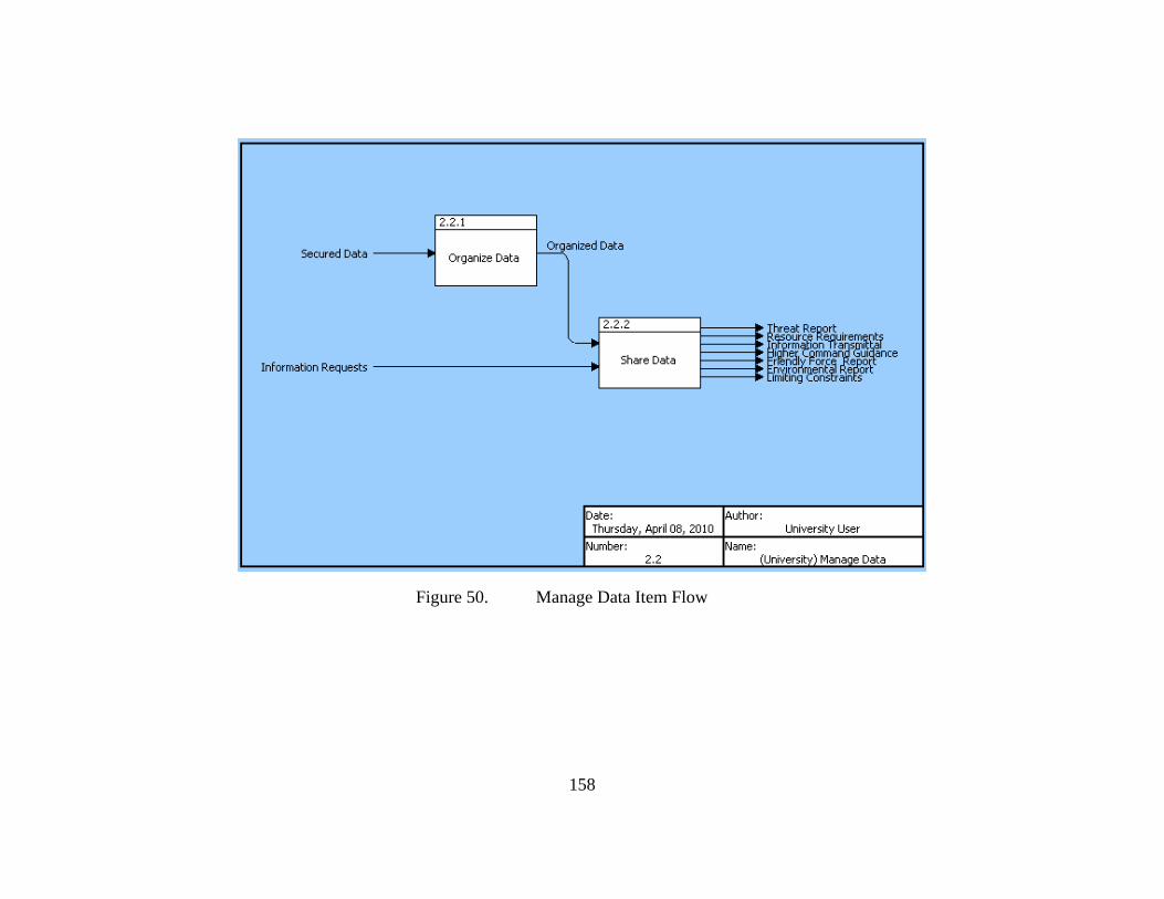
158
Figure 50. Manage Data Item Flow

159
Figure 50. is the item flow illustration for the functions which decompose
Manage Data. All of the inputs and outputs have been discussed previously with the
exception of the output Organized Data. Organized Data is the data which has been
filtered, prioritized, and manipulated into an observable and understandable form. The
goal of the Organized Data is to present information to C2 nodes that is useful and
manageable, not overwhelming. Share data is the uploading of information to a
collaborative network in order to increase each internal operational node's understanding
of the situation and also to inform external stakeholders that interface with the network.
4.1.3.4. Conduct UV Operations
Conduct UV Operations entails the mission accomplishment that is carried
out by unmanned vehicles and other assets in the battlespace, such as manned vehicles.
This functional breakdown will focus on the UVs, however, the information exchange
between UVs and manned vehicles is a critical component and are discussed in more
detail in Section 4.2. The concept of operations envisions the UVs as operating with one
UV as a “Master” and the other UVs as the “Subordinates.” The master UV
communicates with the subordinate UVs and also communicates with the Collaborative
Network. Each UV can assume the role as master if the current master is unable to
perform the role. The “Master” and “Subordinate” role is discussed in more detail in
Section 4.2.
Below are the architectural products for the function Conduct UV
Operations. Figure 51. will shows the hierarchy, Figure 52. shows the functional flow.
Table 19 and Figure 53. through Figure 55. will show the input/output of each function.
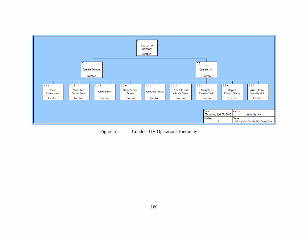
160
Figure 51. Conduct UV Operations Hierarchy

161
Figure 51. shows the functional decomposition of Conduct UV
Operations. This function is broken down to two primary sub functions, Operate Sensors
and Operate UVs.
Operate Sensors is the utilization of sensors onboard UVs, such as optical,
infrared, acoustic, weather reading, RADAR, temperature, other sensors that are utilized
by vehicles. Operate Sensors is decomposed by: Sense Environment, Share Raw Sensor
Data, Fuse Sensors, and Share Sensor Picture. Sense Environment is the identifying,
reading, and exploiting of observables in the environment. Observables could be
vibrations, electromagnetic radiation, acoustic waves, and many other forms of stimuli.
Share Raw Sensor Data is the sending of sensor data to other vehicles in the vicinity for
greater situational awareness amongst operational nodes. These other vehicles could be
other UVs or manned vehicles. Fuse Sensors is the combining of many different sensor
feeds to create a situational picture or sensor picture. For example, an optical feed of a
target from a UV could be correlated to an acoustic or RADAR target from a UV or
manned vehicle, thereby giving the type of target, and the course and speed of target.
Share Sensor Picture is the communication of the fused sensor picture to
the collaborative network and other vehicles. The objective of the Operate Sensors and
its sub functions is to create a shared awareness of the operational environment that can
be acted upon.
Operate UVs is the performance of operational activities by UVs in the
battlespace. Activities include navigation, planning, task execution, and reporting.
Operate UVs is decomposed to: Formulate Tactics, Schedule and Allocate Tasks,
Navigate and Execute Tasks, Report Position Status, and Assess and Report Operational
Availability. Formulate Tactics utilizes the artificial intelligence capabilities of UVs, the
sensor picture from UVs, and inputs from C2 nodes, to formulate a tactical plan. The
tactical plan includes maneuver information, sensor usage, weapon usage, and other
relevant tactical tasks for a given situation. Schedule and Allocate Tasks is, given a
tactical plan, the determination of specific tasks required to accomplish the plan. The
tasks are scheduled and allocated to different assets. Navigate and Execute Tasks is the

162
actual maneuvering in a given environment and the carrying out of tasks such as
surveillance. Report Position Status is the sharing to the collaborative network and
required operational assets updates on position and task status. This provides situational
awareness to the nodes in the network. Assess and Report Operational Availability is the
identification of potential problems with the UVs and other equipment and asset that may
hinder operational availability. These functions accomplish the required missions and
feed the situational awareness of the network.

163
Ref.
3
Conduct UVOperations
2
Collaborate
1
Provide C2
AND
OR AND
3.1
Operate Sensors
3.2
Operate UVs
AND OR
Ref.
AND
3
Conduct UVOperations
2
Collaborate
1
Provide C2
Date:Thursday, April 08, 2010
Author:University User
Number:3
Name:(University) Conduct UV Operations
Figure 52. Conduct UV Operations FFBD

164
Figure 52. illustrates that functions Operate Sensors and Operate UVs
occur in parallel. The sensor suites could be collocated with the UV, thus both functions
will occur concurrently. In order to operate UVs to conduct military missions, the use of
sensors are almost always required. For example, a UV conducting a surveillance
mission sends sensor data such as video feeds to required C2 nodes.

165
Table 19 provides a tabular representation of the inputs to and outputs
from Conduct UV Operations. This table will assist the understanding of the subsequent
item flow diagrams.
TABLE 19. CONDUCT UV OPERATIONS INPUT/OUTPUT.
INPUT FUNCTION OUTPUT UV Control Order Resource Orders Observables Mission Tasking
3 Conduct UV Operations
Asset Availability Communication Errors Communication Status Resources Available Shared Sensor Picture UV Control Data (Telemetry) UV Status/Location
Observables 3.1 Operate Sensors Shared Sensor Data Shared Sensor Picture
Observables 3.1.1 Sense Environment Sensor Data Sensor Data 3.1.2 Share Raw Sensor Data Shared Sensor Data Sensor Data 3.1.3 Fuse Sensors Sensor Picture Sensor Picture 3.1.4 Share Sensor Picture Shared Sensor Picture UV Control Order Shared Sensor Picture Shared Sensor Data Resource Orders Mission Tasking
3.2 Operate UVs
Asset Availability Communication Errors Communication Status Resources Availability UV Control Data UV Status/Location
UV Control Order Shared Sensor Picture Shared Sensor Data Resource Orders Mission Tasking
3.2.1 Formulate Tactics
UV Tactical Plan
UV Tactical Plan 3.2.2 Schedule and Allocate Tasks Tasking Order UV Control Order Tasking Order
3.2.3 Navigate/Execute Task
UV Navigation/Task Status
UV Navigation Task Status 3.2.4 Report Position/Status
UV Control Data (Telemetry) UV Status/Location UV System Data
UV System Data 3.2.5 Assess Report Operational Availability
Asset Availability Communication Errors Communication Status Resources Available

166
Figure 53. illustrates the information item flow into and out of the sub
functions of Conduct UV Operations. Observables are input to Operate Sensors.
Observables could be vibrations, electromagnetic radiation, acoustic waves, and many
other stimuli. These stimuli are sensed by UVs and this data is relayed to other UVs or
manned vehicles as Shared Sensor Data. Shared Sensor Data and Shared Sensor Picture
are outputs of Operate Sensors. Shared Sensor Data is sensor data that is transmitted
from one vehicle to other vehicles in order to enhance situational awareness. Shared
Sensor Picture is sensor data that has been fused by the Master UV and then shared to the
C2 network.
UV Status/Location
UV Control Order
UV Control Data (Telemetry)
Shared Sensor PictureShared Sensor Picture
Resources AvailableResource Orders
Observables
Mission TaskingCommunication StatusCommunication ErrorsAsset Availability
Shared Sensor Data3.1
Operate Sensors
3.2
Operate UVs
Date:Thursday, April 08, 2010
Author:University User
Number:3
Name:(University) Conduct UV Operations
Figure 53. Conduct UV Operations Item Flow
The inputs to Operate UVs are Mission Tasking, Resource Orders, and
UV Control Orders, as well as the previously mentioned Sensor Data. Mission Tasking is
an input from a C2 node. Mission tasking is direction specifying the selected course of
action and associated orders to a particular node. Resource Orders required assets, fuel,

167
and support as dictated by the operational environment, friendly capability, and time
criticality. UV control orders are orders given by the C2 node indicating a particular
action to be taken by a UV. The level of control data will vary from a mission update to
an autonomous UV to more consistent stream of control orders to less autonomous UVs.
The outputs of Operate UVs were defined in Figure 49.’s discussion of the
Collaborative Network item flow.
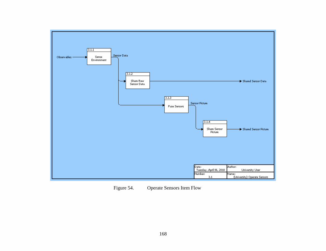
168
Figure 54. Operate Sensors Item Flow

169
Figure 54. is a more detailed view of Operate Sensor’s item flow. All of the items
and functions have been previously defined. This figure shows that after Observables are
transformed by Sense Environment, the Sensor Data enters the functions Share Raw Sensor Data
and Fuse Sensors. Shared Raw Sensor Data’s output is Shared Sensor Data which is sent to
other operational vehicles to enhance their situational awareness. The output from Fuse Sensors
is the Sensor Picture which is shared to the Collaborative Net in order to facilitate C2 efforts.

170
Figure 55. Operate UV Item Flow

171
Figure 55. shows a more detailed breakdown of Operate UV’s item flow.
The input UV Control Order is input to both Formulate Tactics and Navigate/Execute
Task. The UV Control Order provides the Formulate Tactics function an indication of
where and what the UVs are doing. The UV Control Order is the C2 node’s direction for
the UV. The level of detail of the order will vary based on the level of autonomy of the
UV. The output from Formulate Tactics is the UV Tactical Plan, which is a plan
detailing how the UVs will accomplish a particular mission. For example, the plan could
indicate which sectors different UVs will need to monitor while conducting a force
protection mission. The UV Tactical Plan is the input for Schedule and Allocate Tasks.
The output from Schedule and Allocate Tasks is the Tasking Order which gives specific
direction to assets in order to execute a plan. For example, the order would assign a
specific location for a UV to proceed to. The Tasking Order is the input for
Navigate/Execute Task which results in the output UV Navigation/Task Status. The UV
Navigation/ Task Status is an update on the navigational information such as location,
course, and speed of the UV and the completion progress of the tasks it was assigned to
complete. The UV Navigation/Task Status is input to Report Position/Status. The
outputs of Report Position/Status are the UV System Data, UV Status/Location, and UV
Control Data (Telemetry). UV Status/Location and UV Control Data (Telemetry) were
discussed earlier when discussing inputs to the Collect sub function of Collaborate. UV
System Data is input to Assess/Report Operational Availability and is the information
which allows the assessment of the UVs operational status, including communication
status, communication errors, resource levels, and asset availability. The outputs of
Assess/Report Operational Availability were defined earlier as inputs to the Collect sub
function of Collaborate. Assess/Report Operational Availability’s outputs assist in the
C2 nodes’ understanding of what the operational assets level of readiness and resource
requirements.
4.1.3.5. Functional Measures of Effectiveness
Table 20 shows each function’s MOE and unit of measure. The MOE is a
measure of successful performance of a function. The performance of the function

172
should contribute to overall mission performance. The units of measure are specific ways
that the MOEs are evaluated, such as percentages, seconds, and numerical values.
Section 5 will discuss the specific MOEs that were utilized to conduct modeling and
analysis.

173
Function MOEs Units of Measure 1 Provide C2
Link/communications (comms) availability
Percent comms availability (network uptime / total operation time)
Availability of information sources
Percent info availability (lowest comms availability of all network nodes)
1.1 Observe
Timeliness of information [detection to identification to availability of information on network (time target information is uploaded on network – time detected)]
Seconds
Capability of sense making tools (track fusion, data correlation, cognitive processing, considerations for HFE in interface design, etc.)
Percent target correlated (targets correlated / total target tracks)
1.2 Orient
Capability of analysis tools (estimate of current situation, determining mission gaps, etc.)
Percent correct estimate (correct predicted situation / updated situation)
Competency of decision makers in setting/formulation of clear goals/objectives
Percentage of orders issued that are executed as intended (Correctly executed orders/total orders)
1.3 Decide
Ability to propose COAs that improve situation which is difference between desired state and actual state
Numerical scale (i.e. 5 equals high improvement, 1 equals little improvement)

174
Competency of decision makers in deciding C OA (possibly computer assisted or deliberate deviation from proposed COA)"
Percentage of COAs that meet mission objectives. (Successful COAs/Total COAs)
Link/comms availability
Percent comms availability (network uptime / total operation time)
Operator competency Numerical scale (i.e. 5 equals high competency, 1 equals low competency)
1.4 Act
Clarity of mission, clarity of goals/objectives
Mission accomplishment rate (successful missions / total missions)
1.5 Share to Network Link/comms availability
Percent comms availability (network uptime / total operation time)
2 Collaborate 2.1 Operate in Network Link/comms
availability Percent comms availability (network uptime / total operation time)
Availability of information
Percent info availability (lowest comms availability of all network nodes)
2.2 Manage Data
Timeliness of information
Seconds
2.3 Collect Data Ease of storage/retrieval of data (HMI design issue)
Numerical scale (i.e. 5 equals simple, 1 equals difficult)
Security policies set in place
Percentage of successful attacks (successful attacks/total attacks)
2.4 Secure Network
Number of network attacks (time normalized)
Number of outages per time period (e.g. per month)
3 Conduct UV Operations 3.1 Operate Sensors Operator competency
Numerical scale (i.e. 5 equals high competency, 1 equals low competency)
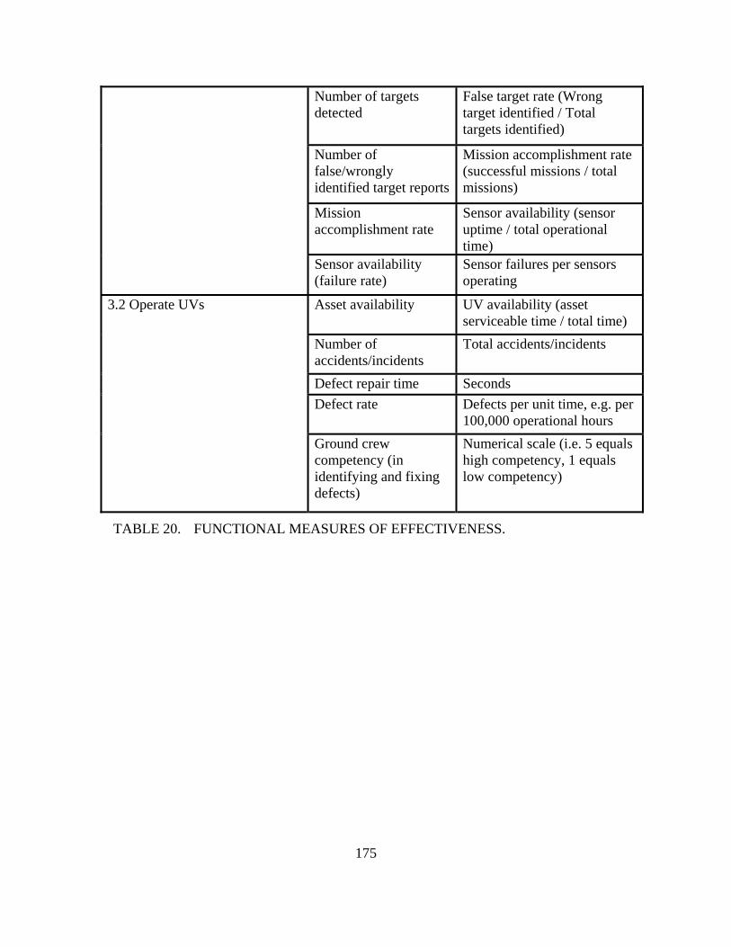
175
TABLE 20. FUNCTIONAL MEASURES OF EFFECTIVENESS.
Number of targets detected
False target rate (Wrong target identified / Total targets identified)
Number of false/wrongly identified target reports
Mission accomplishment rate (successful missions / total missions)
Mission accomplishment rate
Sensor availability (sensor uptime / total operational time)
Sensor availability (failure rate)
Sensor failures per sensors operating
Asset availability UV availability (asset serviceable time / total time)
Number of accidents/incidents
Total accidents/incidents
Defect repair time Seconds Defect rate Defects per unit time, e.g. per
100,000 operational hours
3.2 Operate UVs
Ground crew competency (in identifying and fixing defects)
Numerical scale (i.e. 5 equals high competency, 1 equals low competency)
176
4.2. COMMAND AND CONTROL ARCHITECTURE
4.2.1. C2 Architecture Considerations in Unmanned Platform
Unmanned platforms are “edge entities” within the Global Information Grid. On
its own, it possesses knowledge of local situational awareness and contributes to mission
objectives in a known and pre-established manner. According to Network Centric
Warfare principles, this knowledge can be disseminated to a robustly networked force to
realize the benefits of Metcalfe’s Law108. There are a number of challenges to fully
realizing such a concept. This section highlights key considerations in formulating a
Command and Control (C2) architecture for supporting unmanned vehicles and its
operations.
In most organizations, it is generally difficult to realize Gilder’s Law109 without
significant infrastructural investments. This is especially true for tactical
communications in the field where it is infeasible to upgrade equipments on a frequent
basis. As such, other alternatives need to be considered to better utilize the bandwidth.
One potential alternative is the use of a cognitive radio that is able to alter its
transmission and reception parameters in response to environmental factors for effective
communication. Most unmanned platforms also have power constraints that limit
sustainability and thus, the use of energy efficient waveforms via software defined radio
is a potential research area.
Another candidate for improving bandwidth utilization is through the
development of a Tactical IP communications protocol. This should be interoperable with
traditional TCP/IP for communication to platforms on fixed infrastructure. Traditional
TCP/IP protocol assumes a relatively stable networking environment with low latency.
Hence, it tends to have high overheads (e.g. TCP 3-way handshake) and is generally not
optimized for low bandwidth tactical communications. The new protocol should be
developed to incorporate security mechanisms right from the start that limit identity
spoofing, data modification and other attacks on confidentiality, integrity and availability.
These concepts were previously discussed in Section 3.5.2. 108 Metcalfe's Law states that the value of a network is proportional to the square of the number of nodes in the network. 109 Gilder's Law states that the total bandwidth of communication systems triples every 12 months.

177
Having a networked force is insufficient to realize the benefits of Metcalfe’s Law
unless they are able to communicate with one another effectively. A set of common data
standards is needed to facilitate interoperability among the disparate C2 systems. There
are two levels to interoperability:
At the syntactic level:
• All systems shall adopt standardized data & messaging formats. With a
set of normalized schema, it eliminates the need to perform data
conversion (and thus, no loss of accuracy or granularity) during inter-C2
exchanges.
• Data shall be tagged to indicate sensitivity and integrity markings. Hosts
are to support the common use of digital signatures and cryptographic
algorithms.
• All systems shall adopt an IP-based protocol. This reduces the need for
dedicated gateway nodes for bridging communications and hence,
resulting in faster OODA cycle.
At the semantic level:
• This refers to systems having the ability to interpret exchanged
information in a meaningful and accurate manner. To accomplish
this, it is essential to have an information exchange reference
model where information exchange requests are unambiguously
defined.
• Inadvertently, this information exchange is often tied to doctrinal
and operational procedures and it may be relevant to assess
whether they should be further refined.
After the C2 systems are able to communicate with one another, they need a
mechanism to facilitate sense making. This may be accomplished by having a common
operating picture that can be achieved by aggregating information from various
networked sensors and presenting them in a cognitive manner. The use of Bayesian
178
network techniques can be deployed to infer likelihood of compromised host or
performing data fusion when multiple sensors are reporting the same target. To reduce
information overload, C2 systems may adopt a “publish and subscribe” technique on their
area of interest instead of being presented with every piece of incoming information.
4.2.2. OV-1 High Level Operational Concept Graphic
The followings are the key capabilities of the UV fighting forces that the
proposed C2 architecture addressed. Figure 56. shows graphically the concept of the
system.
• Self-protection - With the advent of more intelligent unmanned platforms
being used in the theater and the advancement in artificial intelligence,
these unmanned platforms could be used as a part of self-protection
tactics. They could either be used as 'shields' for high value assets due to
their relative cost in terms of monetary value or human lives or used as
forward sensors to detect external threats such as high speed, low
probability of detection missiles. The sensor range could be extend
beyond typical radars, even into dangerous zones where there is a high
probability of detection and risk of being taken down by enemy fire.
• Self-forming / self-healing networks - When squadrons of unmanned
platforms are being sent into the combat zones where they are within the
range of enemy sensor detection and fire, they bear the risk of being
destroyed by low cost interceptors, such as improvised rockets that are
being used in asymmetric warfare. In such scenarios, the concept of self-
healing and self-forming networks is critical to ensure that the mission
could still be carried out despite one of the leading platforms are being
destroyed. Mechanisms to ensure proper succession to the being the
master node is necessary. Adaptive routing of networks paths would be
also required to ensure critical information/data can still be transmitted
back to headquarters.

179
• Cross-medium rebroadcast - The operational environment comprises of
several mediums, including space, air, land and sea, both surface and
underwater. In order for optimal reach of data communications and
network redundancy, there is a need to develop cross-medium rebroadcast
capabilities. This would not only extend the range of communications but
also the survivability of the networks. When a particular medium is
jammed and denied, the network should remain functional by using
another medium for communications using intelligence bandwidth
allocation and rebroadcast capabilities.
• Sensor / platform diversity - To ensure maximal detection, a suite of
different sensors being used with different angles of perspectives would be
necessary. Hence, there is a need for different platforms and sensors to
work collaboratively to ensure maximum sensor coverage and complete
situational awareness. This would also mean that the unmanned platforms
must be able to communicate and command with one another to
collaboratively work towards the common mission.
The current C2 architectures would be unable to support these kinds of
capabilities because most of them are too focused on specific missions to allow
effective flow of commands and information among different nodes. A robust
architecture such as the one proposed would need to be built to support the
dynamic nature of the new UV fighting forces.

180
Figure 56. OV-1 High Level Operational Concept Graphic
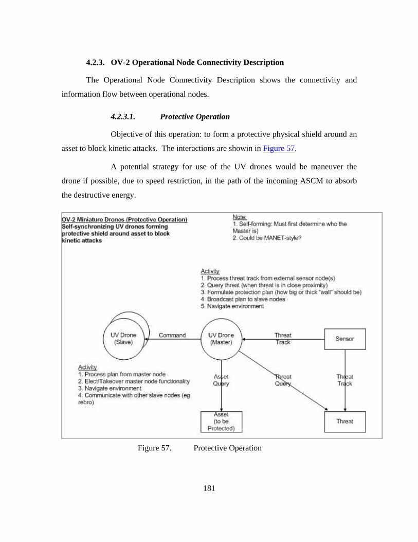
181
4.2.3. OV-2 Operational Node Connectivity Description
The Operational Node Connectivity Description shows the connectivity and
information flow between operational nodes.
4.2.3.1. Protective Operation
Objective of this operation: to form a protective physical shield around an
asset to block kinetic attacks. The interactions are showin in Figure 57.
A potential strategy for use of the UV drones would be maneuver the
drone if possible, due to speed restriction, in the path of the incoming ASCM to absorb
the destructive energy.
Figure 57. Protective Operation

182
4.2.3.1.1. Activities at the Master Drone:
The Master Drone is responsible for the processing of the threat track (location,
altitude, velocity, and heading) from an external source, such as a sensor node. If
the threat is within proximity of the swarm, the master drone takes responsibility
to identify the threat and to query it, comparing it to its own repository of known
threats, or with higher echelon of command. Once the threat track has been
established, the Master Drone has to formulate a protection plan to be
disseminated to the sub-ordinates under its command. The plan would include the
number of sub-ordinate UVs to call upon, and the instructions to be given to each
sub-ordinate to move into position (lat-long and altitude) with the precise timing
to intercept the attack. The Master Drone will need to be able to broadcast the
protection plan to the selected sub-ordinates, and ensure the sub-ordinate UVs are
responding and moving according to the plan. The Master Drone will need to use
its own sensors, together with situational awareness from sub-ordinate UVs or
higher echelons to navigate the surrounding environment, taking into
consideration both geographical features as well as strategic boundaries such as
no-fly zones or political borders. It also has to determine the general heading and
speed of the UV swarm it is responsible for.
4.2.3.1.2 Activities at the Sub-ordinate Drone:
The Sub-ordinate drone processes protection plans from the Master drone, and
adjusts its heading and speed according to the instructions received. It must
simultaneously be able to navigate the environment using its own sensors, in
order to avoid collisions with other drones and geographic features. The Sub-
ordinate Drone will have the ability to take-over and perform all Master drone
activities, should there be a catastrophic loss of the Master drone. The Sub-
ordinate drone also functions as a communications node to re-broadcast messages
from the Master drone to drones that may have temporarily lost direct
communications with the Master drone.

183
4.2.3.2. Search Operation
Objective of this operation: To collectively and synergistically search
for and track targets in an area of operations, using a combination of sensors distributed
over the UV swarm. Different types of sensors (for instance, radar, electro-optical /
infra-red, hyper-spectral imaging) have varying effectiveness in finding targets in
different terrain. With a mix of sensors looking at the same area of operations, there is
higher chance of finding elusive targets. The interactions are showin in Figure 58.
Figure 58. Search Operation
The UV drones receive command intent, including the area to search and a list of
possible targets, from the command node (could be the headquarters), and will send
target update reports back to the command node regarding the targets that have been
detected.
The UV drones synchronize among themselves to determine search regions within
their area of operations that have not been searched yet. Search regions are prioritized by

184
age of the last scan, the oldest region receiving the highest priority, since there could
have been fresh target movements that have not been detected since the last scan of the
region. A search plan is formulated (by the Master drone) and one (or more) Sub-
ordinate UVs are tasked with searching a region. Targets may require several scans by
different sensor types before being identified (for instance, a radar track indicating a
target will need to be further examined by EO/IR sensors for classification and
identification), so the UV drones will co-ordinate among themselves for the need to
relocate the required sensors to further scan the tracks that have been found. Once targets
are are identified, the threat location (co-ordinates and heading) is reported to the
command node.
4.2.4. OV-3 Operational Information Exchange Matrix
The Operational Information Exchange Matrix (OV-3) shows the information
exchanged between nodes, the relevant attributes of that exchange such as media, quality,
quantity, and the level of interoperability required.

185
4.2.4.1. Information Exchange Model
An Information Exchange Model was derived to aid in the creation of the
OV-3 matrix. Figure 59. illustrates this Information Exchange Model, and the typical
flow of information between three types of nodes in an operational setting: a
Headquarters (HQ), Manned System (MS) and Unmanned Vehicle (UV).
Figure 59. Information Exchange Model for Command and Control

186
4.2.4.2. Categories of Information Exchange
The various types of information exchanged in a typical operational
setting can be grouped into the following categories:
• Information type – defines the origin and type of information
source.
• Data type – defines the type of data to be transmitted.
• Bandwidth – defines the amount of resources that a Command and
Control system needs to devote to transmit the information. ‘High’
refers to a range of more than 80kbps, ‘Medium’ refers to the
range of 10 – 80kbps, and ‘Low’ refers to a range of less than 1-
kbps.
• Timeliness – defines how timely urgent the information needs to
be sent to a recipient node.
• Triggering events – defines the events that will trigger the sending
of such information.
• CIA – defines the amount of Information Assurance required to
protect the information, in terms of its Confidentiality, Integrity
and Availability.
o Confidentiality is defined as ensuring that information is
accessible only to those authorized to have access.
o Integrity refers to the condition that data cannot be created,
changed, or deleted without proper authorization.
o Availability is defined as having timely and reliable access
to data and information services for authorized users.

187
4.2.4.3. MS/ UV (Master)-to-HQ Information Exchange
Table 21 below shows the types of information that a MS or UV (Master)
needs to send to HQ.
TABLE 21. MS / UV (MASTER)-TO-HQ INFORMATION EXCHANGE.
188
In a typical swarm network concept of operations, the UV-Master will
collate all relevant information from their UV-Subordinates and transmit only the
necessary information back to HQ. The UV Master does not need to send all the
information. Each element in the system sends only the relevant portions of data
necessary to synchronize the common picture, resulting in a smaller bandwidth
requirement.
The implications are that the C2 architecture is expected to be loaded the
most especially if this involves the transmission of live video sensor feeds, which
requires the highest bandwidth and lowest latency in the order of milliseconds.
Thus, for concepts of operations involving swarm operations and video
feeds transmission, it is recommended that Operational Research (OR) tools be exploited
to determine the optimal force numbers that the C2 architecture can handle, and yet not
be overwhelmed by the bandwidth required.
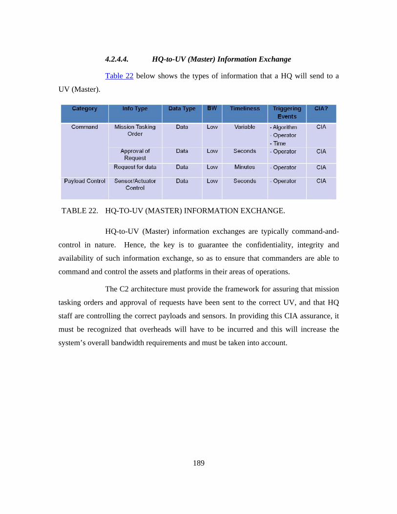
189
4.2.4.4. HQ-to-UV (Master) Information Exchange
Table 22 below shows the types of information that a HQ will send to a
UV (Master).
TABLE 22. HQ-TO-UV (MASTER) INFORMATION EXCHANGE.
HQ-to-UV (Master) information exchanges are typically command-and-
control in nature. Hence, the key is to guarantee the confidentiality, integrity and
availability of such information exchange, so as to ensure that commanders are able to
command and control the assets and platforms in their areas of operations.
The C2 architecture must provide the framework for assuring that mission
tasking orders and approval of requests have been sent to the correct UV, and that HQ
staff are controlling the correct payloads and sensors. In providing this CIA assurance, it
must be recognized that overheads will have to be incurred and this will increase the
system’s overall bandwidth requirements and must be taken into account.

190
4.2.4.5. HQ-to-MS Information Exchange
Table 23 below shows the types of information that a HQ will send to a
MS.
TABLE 23. HQ-TO-MS INFORMATION EXCHANGE.
Similarly, HQ-to-MS information exchanges are typically command-and-
control in nature, and thus should focus on achieving confidentiality, integrity and
availability.
4.2.4.6. UV (Master)-to-UV (Subordinate) Information Exchange
Table 24 below shows the types of information that a UV (Master) will
send to a UV (Subordinate).
TABLE 24. UV (MASTER)-TO-UV (SUBORDINATE) INFORMATION
EXCHANGE.

191
In a swarm operation, UV-Master-to-UV-Subordinate information
exchanges play a crucial role as the UV-Master is in command and control of all UV-
Subordinates under their charge, and thus is responsible for issuing command orders and
redirecting them for tasking during operations.
Without the man-in-the-loop element, there must be a secure mechanism
for guaranteeing that issued mission orders are genuine and valid. Again, this can be
done by focusing on the confidentiality, integrity and availability of such information
exchanges.
4.2.4.7. UV (Subordinate)-to-UV (Master) Information Exchange
Table 25 below shows the types of information that a UV (Subordinate)
will send to a UV (Master).
TABLE 25. UV (SUBORDINATE)-TO-UV (MASTER) INFORMATION
EXCHANGE.
192
In a swarm network, the bandwidth of such information exchanges will
depend on the ratio of UV-Subordinates to UV-Masters in the network, as well as the
nature of the mission.
Concepts of operations that will load the C2 architecture the most are
swarm operations with a high UV-Subordinate to UV-Master ratio and Intelligence
Surveillance and Reconnaissance missions involving the transmission of live video
sensor feeds, which requires the highest bandwidth and lowest latency in the order of
milliseconds.
4.2.4.8. Concluding Remarks
The OV-3 Informational Exchange Matrix will allow planners of the C2
architecture to gain insights into which aspects of the architecture are subjected to the
most loading, as well as the types of operational scenarios that will cause the loading.
Through that, the optimal force composition and numbers can be determined via the use
of appropriate OR simulation tools to stress-test the architecture.
4.2.5. OV-5 Operational Activity Model
The Operational Activity Model (OV-5) shows the activities, relationships among
activities, inputs and outputs of the different system nodes.
The OV-5 models for force protection and reconnaissance operations are being
constructed.

193
4.2.5.1. OV-5 Force Protection
Figure 60. Operational Activity Model (OV-5) for Force Protection
Figure 60. shows the Operational Activity Model (OV-5) for Force Protection
scenario. UV will exchange data with External Sensors and send Assets and Threats
information to the Collaboration Net. The Collaboration Net sends Threats information to
HQ where HQ will use it in mission planning. Activities for UV include sense
environment, assess friendly capability, assess threats and risks, analyze environment,
develop COA, carry out assigned mission, navigation and update mission status. For the
External sensors, their main activities are sense environment and update mission tasks
status. Collaboration Net basically publish Assets and Threats information which is send
to HQ for mission planning. HQ will make use of Assets and Threats information for
planning. Commands are then send to UV by HQ. HQ will also receive tasks status

194
updates from Collaboration Net which receive the status information from both external
sensors and UV.
4.2.5.2. OV-5 Reconnaissance
Figure 61. Operational Activity Model (OV-5) for Reconnaissance
The Operational Activity Model (OV-5) for the Reconnaissance scenario is shown
in Figure 61. In the diagram, the UV exchanges information with External Sensors and
send data to Collaboration Net. The Collaboration Net processes the input data from UV
and send a sensor picture to HQ so that HQ can make use of the processed sensor picture
in planning. The HQ will then interact with the UV by sending commands to UV.
Activities carried out by UV are Sense environments, develop COA, navigate and update
position and status. External sensors sense the environment for potential threats.
Collaboration net will process data to useful information for HQ. HQ will further analyze
the useful information and use it for planning purposes.
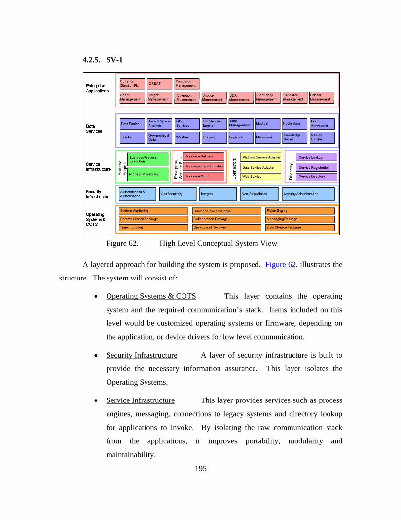
195
4.2.5. SV-1
Figure 62. High Level Conceptual System View
A layered approach for building the system is proposed. Figure 62. illustrates the
structure. The system will consist of:
• Operating Systems & COTS This layer contains the operating
system and the required communication’s stack. Items included on this
level would be customized operating systems or firmware, depending on
the application, or device drivers for low level communication.
• Security Infrastructure A layer of security infrastructure is built to
provide the necessary information assurance. This layer isolates the
Operating Systems.
• Service Infrastructure This layer provides services such as process
engines, messaging, connections to legacy systems and directory lookup
for applications to invoke. By isolating the raw communication stack
from the applications, it improves portability, modularity and
maintainability.
196
• Data Services This layer provides a standard interface for the
various disparate data forms/format. Additionally, this data layer serves
the enterprise applications to form a service-oriented framework.
• Enterprise Applications The final layer allows custom built
applications to support different environments and missions. Unlike the
previous layers, the enterprise application layer can be installed on the
platform itself.
4.2.6. Communications and Network
The Communications and Network (CN) systems provide the transport
mechanism to deliver information between blue-force entities in a timely and organized
manner. In the C2 process, the CN systems link geo-dispersed sensor information to
form a live common operational picture. The live common operational picture allows
commanders to react in a timely fashion and make well-informed decisions in response to
changing events. CN systems support efficient and effective dissemination of orders to
the nodes which execute the counter measures. The aim is to shorten the "sensor-to-
shooter" time in the OODA cycle.
In general, the ideal CN systems will fulfill operational demands in the following
aspects:
Connectivity: To connect entities that requires exchanging information
during the operation. For wireless communications, direct connectivity is determined by
the range of CN systems deployed in the mission. If the information source is not within
range of information sink, then multiple hop connectivity may be required to bridge the
gap.
Range: The communication range is expected to be as large as possible to
allow dynamic of force projection with minimum need of deploying intermediate re-
broadcast stations.
Channel capacity: To provide adequate channel capacity to deliver
information at the rate required by the C2 applications. Types of data traffic may vary

197
from lightweight track information packets to heavyweight streaming traffic like video
teleconferencing (VTC) sessions.
Latency & Jitter: Time-critical application traffic, e.g. targeting information
to guide missile to fast moving target, requires near real-time end-to-end latency in order
to be effective. Time-sensitive application, e.g. video / audio streaming are sensitive to
jitter.
Information Assurance: here is a need to denying adversaries from
exploiting the information that was transmitted in the common exposed medium and turn
it against our blue forces.
Link Reliability: Communications on-the-move in a multi-path environment
suffers multipath fading that disrupts communications connectivity
Resource optimization: To meet the growing demand of channel capacity,
there is a need to optimize the spectrum utilization efficiency. Dynamic assigned
multiple access (DAMA) schemes should be employed whenever possible to ensure that
every subscriber station access the transmission medium only when it has data to
transmit.
Low Probability of Interception/ Detection (LPI/LPD): To increase the
survivability probability of our blue-forces operating in the tactical environment, there is
a need to deny adversaries from exploiting our wireless transmission with their electronic
warfare (EW) capability.
High Service Availability: To provision systems redundancy and avoid
designing single-point of failure in CN architecture. Service recovery process has to be
rapid and responsive to minimize service downtime.
4.2.6.1. Communications & Network Topology
The CN topology and concepts support Unmanned systems (UMS) which
operate in the air, land and sea domains.
UMS (Air/ Surface) Operation

198
Satellite communications (SATCOM) offer global area coverage that
enables beyond-line-of-sight (BLOS) communications between forces. By the year 2030,
UMS technology will have achieved high levels of autonomy for executing missions.
UMS operators will no longer need to assert direct control of the UMS platforms.
For large-scale clustered UMS operating at BLOS range (>1000km), it is
difficult to connect every UMS to their command center, in terms of SATCOM RF
spectrum. The Master-Subordinate operation concept was introduced to reduce the
reach-back traffic demand by the UMS cluster. This transforms a STAR-topology to a
TREE topology for the tactical wireless network. This is shown in Figure 63.
Figure 63. Global Coverage
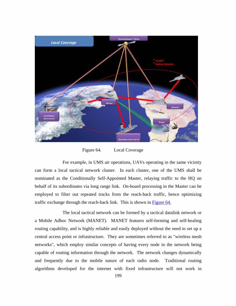
199
Figure 64. Local Coverage
For example, in UMS air operations, UAVs operating in the same vicinity
can form a local tactical network cluster. In each cluster, one of the UMS shall be
nominated as the Conditionally Self-Appointed Master, relaying traffic to the HQ on
behalf of its subordinates via long range link. On-board processing in the Master can be
employed to filter out repeated tracks from the reach-back traffic, hence optimizing
traffic exchange through the reach-back link. This is shown in Figure 64.
The local tactical network can be formed by a tactical datalink network or
a Mobile Adhoc Network (MANET). MANET features self-forming and self-healing
routing capability, and is highly reliable and easily deployed without the need to set up a
central access point or infrastructure. They are sometimes referred to as "wireless mesh
networks", which employ similar concepts of having every node in the network being
capable of routing information through the network. The network changes dynamically
and frequently due to the mobile nature of each radio node. Traditional routing
algorithms developed for the internet with fixed infrastructure will not work in

200
environments where nodes can join and leave the network at any time. The routing may
pass through several heterogeneous links with different capabilities. Therefore, self-
forming and self-healing networks are evolving areas of research for finding efficient
routing protocols and optimizing the channel utilization with minimal packet collision
and idle time.110
During operation, if the Master is destroyed or isolated from the cluster,
the tactical network shall re-nominate a new Master within the cluster. This approach
eliminates single point of failure to assure high availability.
UMS (Land) Operation:
For large-scale, land-based UMS platforms, the direct ground-to-ground
communications links are generally subjected to lateral foliage penetration attenuation
and terrain blockage. This reduces the range of direct communications link between
land based UMS and other nodes. While SATCOM offers a quick solution for coverage,
connecting large number of UMS platforms via global SATCOM coverage may deplete
SATCOM resources.
110 Motorola Technology Position Paper, Mesh Networks, Motorola Inc. http://www.motorola.com/staticfiles/Business/Products/Wireless%20Broadband%20Networks/Mesh%20Networks/_Documents/_static%20file/wp_technology_position_paper.pdf (accessed June 4, 2010) Wikipedia, Wireless mesh network, http://en.wikipedia.org/wiki/Wireless_mesh_network(accessed June 4, 2010); Wikipedia, Mobile ad hoc network, http://en.wikipedia.org/wiki/MANET(accessed June 4, 2010)
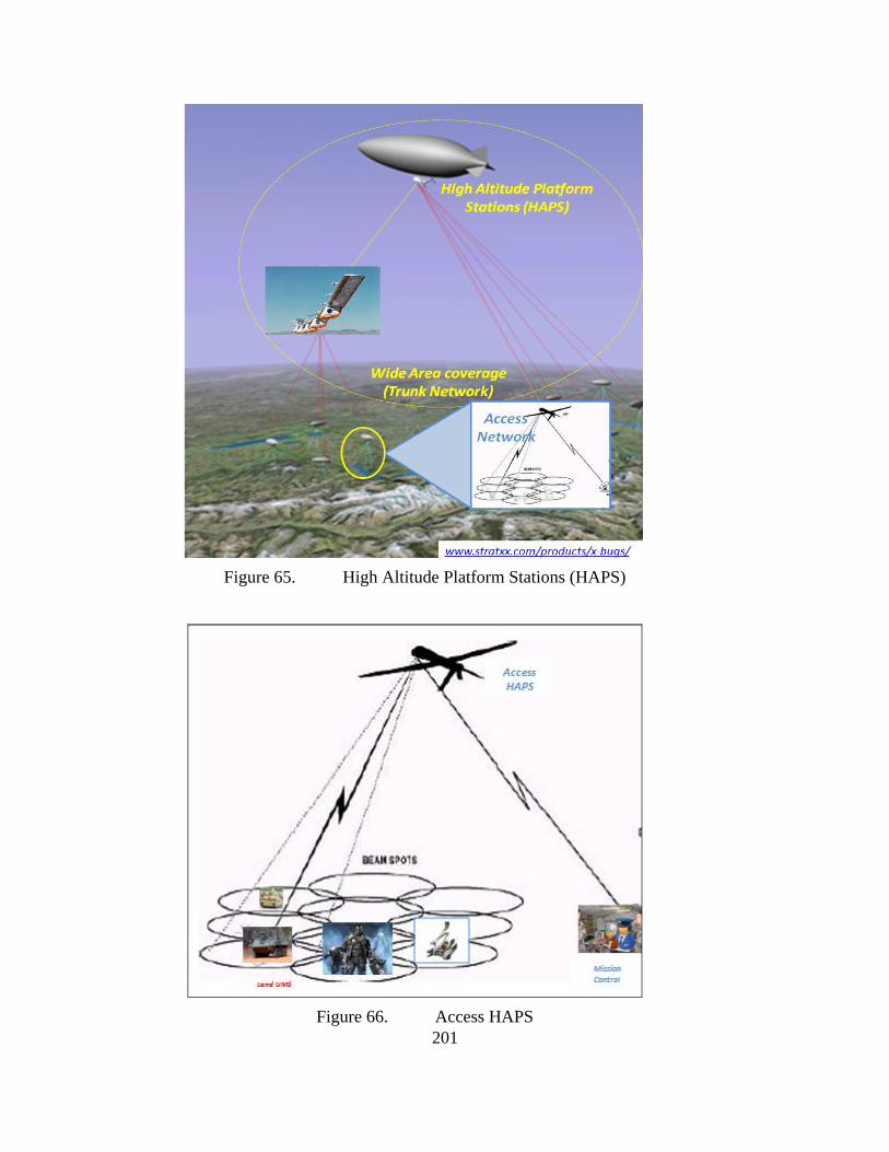
201
Figure 65. High Altitude Platform Stations (HAPS)
Figure 66. Access HAPS

202
An alternative to SATCOM is the use of an aerial communications node
(ACN). These utilize a relay concept using high-altitude, high-endurance surrogate
satellite platforms, such as High-Altitude Platform Stations (HAPS), as shown in Figure
65. HAPS is an intermediate alternative that provides additional link capacity while
overcoming foliage and terrain challenges faced by the UMS operation. The UMS can be
linked to Access HAPS, as shown in Figure 66., which cover their region. Potential
technologies today for access network are Tactical Datalink and WiMax. The high
elevation-angle reduces foliage penetration and lowers the probability of terrain
blockage. The link of cellular base-station to the Access HAPS or HAPS form a multi-
tier core network backbone to extend the coverage of the wide area communications over
land theater.
UMS (Underwater) Operation
In addition to acoustic waves there are other means for wireless
transmission of signals under water. Very low frequencyradio waves (30Hz - 300Hz)
will propagate through conductive sea water, but require large antennas and high
transmitter power. Optical waves do not suffer so much from attenuation, but they are
affected by scattering. While laser technology is still being perfected for practical use,
acoustic waves remain the optimum solution for communicating under water in
applications where tethering is unacceptable.
The achievable data throughput and the reliability of underwater acoustic
communication systems are measured by the bit error probability. This probability varies
from system to system, but is always subject to bandwidth limitations of the ocean
channel. In the existing systems, there are usually four kinds of signals that are
transmitted: control, telemetry, speech and video signals.
During the past few years, significant advancements have been made in
the development of underwater acoustic communication systems in terms of their
operational range and the data throughput. Acoustically controlled robots have been used
to replace divers in performing maintenance of submerged platforms. High quality video

203
transmission from the bottom of deep ocean trenches (6500m) to surface ships and data
telemetry over-the-horizon has been demonstated.
The emerging communication scenario in which the modern underwater
acoustic systems will operate is that of an underwater data network consisting of both
stationary and mobile nodes. These nodes can be located on UUVs, bouys, or permenant
nodes mounted on the sea bed. This network is envisioned to provide exchange of data
such as control, telemetry and video signals between multiple network nodes. Remote
users will have access to the network via radio link connecting to a central node based on
a surface station.111
Despite its long range performance, propagation velocity of acoustic
waves in water (~1500m/s) is 200,000 times slower that RF propagation (3 x 10⁸m/s).
This effect will have an impact regarding the speed of transmission. If the signal is
transmitted across long range acoustic communications, the application will suffer
significant end-to-end latency. For example, a 3km acoustic link has a latency of two
seconds. Hence the range of the "last-mile" acoustic link is limited by the most latency
requirement that the UMS requires to operate effectively for its mission. This depends on
the type of applications that the acoustic communications link needs to support.
Interactive control using live video feedback, sensor feed, and telemetry data are
examples of these applications. Also, medium access schemes supporting the multiple
user access within the local area network needs to have sufficient guard interval or back-
off time to avoid transmission collision between different mobile stations.
SATCOM or surrogate satellites can be used to bridge the long range gap
between the C2 center and large number of remote UMS while maintaining long stand-
off distance.
111 Milica Stojanovic, Underwater Acoustic Communication, Department of Electrical and Computer
Engineering, Northeastern University. Wiley Encyclopedia of Electrical and Electronics Engineering. http://web.mit.edu/people/millitsa/resources/pdfs/ency.pdf (assessed on June 4, 2010)

204
The cluster concept can be applied to UUVs, with a Master undertaking
the role of RF-to-Acoustic communications relay and utilizing acoustic communications
to facilitate the cluster local area network. If the tactical mission allows, a surface ship
could be used as both the C2 center and the Master for the cluster network. This is
shown in Figure 67.
Figure 67. Underwater Application of System

205
THIS PAGE INTENTIONALLY LEFT BLANK

206
5.0. EFFECTIVENESS ANALYSIS / FLEET-SIZING
5.1. OBJECTIVE AND APPROACH
5.1.1. ASCM Threat Scenario
In 2030, the US military will continue to rely heavily on its Navy to conduct a
wide spectrum of operations such as: keeping sea lanes open to maintain the flow of trade
and commerce around the world during peacetime, deployment of humanitarian
assistance in the form of personnel and logistics while conducting a disaster relief
operation, and projecting its air and ground forces into the theater of operations during a
time of war. While the US Navy has maintained its dominance of the high seas for
several decades now, new and rising threats such as the development of advanced ASCM
must be addressed in order for the Navy to safeguard its high-value assets such as its
Carrier Battle Groups (CVBG) while conducting these operations in the high seas.
Currently, ASCMs such as the Brahmos112 can travel up to speeds of Mach 3 and
perform intelligent sea-skimming maneuvers to reduce its detection probability after
being launched. In the near future, more advanced ASCMs are expected to travel up to
Mach 4 or even Mach 5, further reducing the reaction time the CVBG has to detect and
destroy the threat. While one missile may not be sufficient to sink a large ship such as a
cruiser or a carrier, any hit would likely reduce its operational effectiveness and prevent it
from fully achieving its mission. Present ASCM tactics also call for the weapons to be
fired in salvos in an attempt to overwhelm the defensive screen. The logic behind any
protection system, therefore, would be to provide detection of the hostile ASCM as early
as possible, so that the CVBG’s own countermeasures such as its anti-missile missiles or
other close-in protection measures can be activated to neutralize the threat in time.
Amidst the CVBGs of today, early warning screens that detect incoming hostile
aircraft are established by tactical warning aircraft such as the E-2C Hawkeye operating
several hundred miles away from the carrier. However, there is a limitation of early
112 The Brahmos was co-developed in India and Russia in 2006, and has an operational speed of 3675
km/h, range of 290 km and carries a 300kg payload.
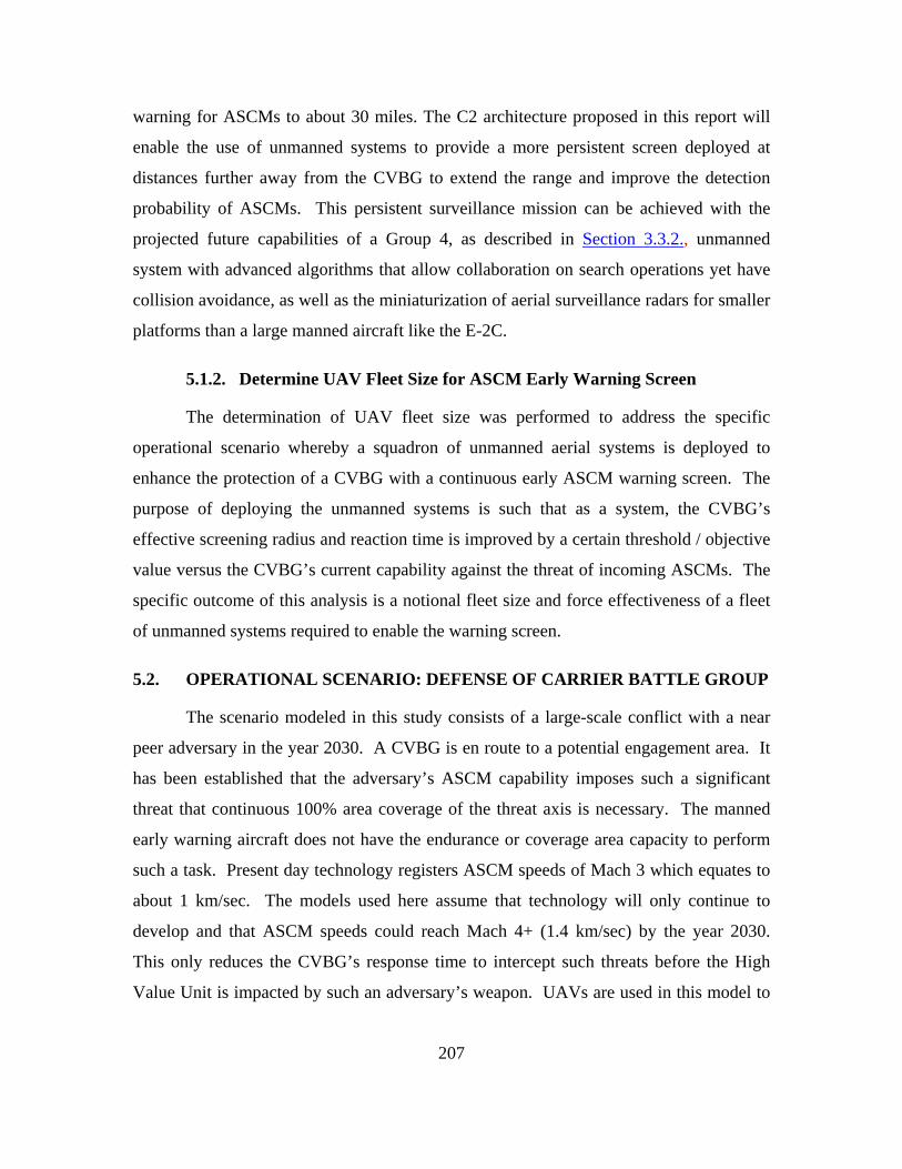
207
warning for ASCMs to about 30 miles. The C2 architecture proposed in this report will
enable the use of unmanned systems to provide a more persistent screen deployed at
distances further away from the CVBG to extend the range and improve the detection
probability of ASCMs. This persistent surveillance mission can be achieved with the
projected future capabilities of a Group 4, as described in Section 3.3.2., unmanned
system with advanced algorithms that allow collaboration on search operations yet have
collision avoidance, as well as the miniaturization of aerial surveillance radars for smaller
platforms than a large manned aircraft like the E-2C.
5.1.2. Determine UAV Fleet Size for ASCM Early Warning Screen
The determination of UAV fleet size was performed to address the specific
operational scenario whereby a squadron of unmanned aerial systems is deployed to
enhance the protection of a CVBG with a continuous early ASCM warning screen. The
purpose of deploying the unmanned systems is such that as a system, the CVBG’s
effective screening radius and reaction time is improved by a certain threshold / objective
value versus the CVBG’s current capability against the threat of incoming ASCMs. The
specific outcome of this analysis is a notional fleet size and force effectiveness of a fleet
of unmanned systems required to enable the warning screen.
5.2. OPERATIONAL SCENARIO: DEFENSE OF CARRIER BATTLE GROUP
The scenario modeled in this study consists of a large-scale conflict with a near
peer adversary in the year 2030. A CVBG is en route to a potential engagement area. It
has been established that the adversary’s ASCM capability imposes such a significant
threat that continuous 100% area coverage of the threat axis is necessary. The manned
early warning aircraft does not have the endurance or coverage area capacity to perform
such a task. Present day technology registers ASCM speeds of Mach 3 which equates to
about 1 km/sec. The models used here assume that technology will only continue to
develop and that ASCM speeds could reach Mach 4+ (1.4 km/sec) by the year 2030.
This only reduces the CVBG’s response time to intercept such threats before the High
Value Unit is impacted by such an adversary’s weapon. UAVs are used in this model to

208
provide expanded radar coverage, which increases the response time for engagement of
ASCMs.
Detection ranges for ASCMs must be greater than what currently provided the
CVBG organic sensors. The enhanced detection range will lengthen the response time in
order for the battle group’s anti-ASCM capabilities to be more effective in protecting the
High Value Unit. Current capabilities used in this study assume 50 seconds from first
detection of an incoming ASCM until impact of the High Value Unit. ASCM defense
procedures use a shoot-shoot-look strategy that takes approximately 15 seconds per cycle.
Time of last launch to successfully interdict the incoming weapon is 10 seconds out,
which puts the ASCM 12-15 km away from the High Value Unit when the last defensive
weapon is away. The UAV early warning screen effectively gives the battle group two
full engagement cycles, with sufficient time to perform a second shoot-shoot-look
engagement after the first, giving the CVBG the opportunity to launch up to four
weapons to intercept the incoming provide for its own defense. This study will show
how a persistent screen of unmanned systems with ASCM detection capability will
enable an increased battle group response time with the capability to counter-shoot more
defensive weapons.
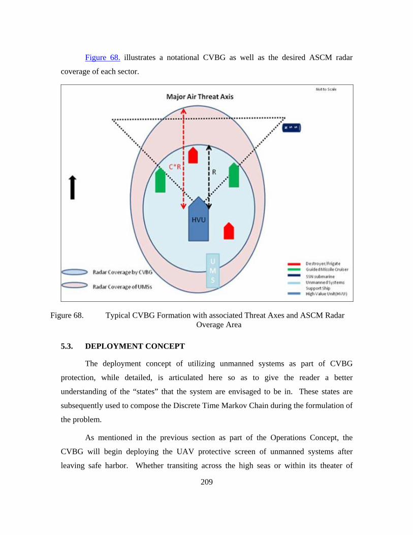
209
Figure 68. illustrates a notational CVBG as well as the desired ASCM radar
coverage of each sector.
Figure 68. Typical CVBG Formation with associated Threat Axes and ASCM Radar Overage Area
5.3. DEPLOYMENT CONCEPT
The deployment concept of utilizing unmanned systems as part of CVBG
protection, while detailed, is articulated here so as to give the reader a better
understanding of the “states” that the system are envisaged to be in. These states are
subsequently used to compose the Discrete Time Markov Chain during the formulation of
the problem.
As mentioned in the previous section as part of the Operations Concept, the
CVBG will begin deploying the UAV protective screen of unmanned systems after
leaving safe harbor. Whether transiting across the high seas or within its theater of

210
operations, the threat protection level as well as the axis of threat focus (thereby
determining the level of coverage desired), is a decision left to commander of the CVBG.
Whether the unmanned systems are launched from a single ship (specially commissioned
to launch, recover and maintain the unmanned systems), or are launched from multiple
ships (each ship within the CVBG today is modified to house part of the system), is also
not prescribed here as part of the problem formulation – the solution can take either form.
As such, a single unmanned aerial platform can be in one of the following states:
State of Ingress - The unmanned platform is launched from its host ship or
airbase, and flies enroute toward its designated patrol orbit. This includes the time it
takes for final operational checks and safety checks to be performed on the platform, the
time it takes to taxi towards the designated runway, time waiting on deck, takeoff time,
and finally flight time towards the holding pattern. Out of all these, the flight time
towards the holding pattern is envisaged to be the longest. During ingress, there is a
probability that the platform will malfunction and be required return to the host ship
without ever reaching the pattern.
Time on Station – Whether as part of the orbiting patrol screen and actively
searching for ASCM or as a “hot standby”, the platform has now reached the designated
patrol orbit and forms part of the overall defensive screen. This is the useful mission
time of the platform. Since there are an optimal number of unmanned platforms in the air
around the CVBG, the new platform that has just completed its ingress to the pattern is
actually replacing another platform that has run low on fuel or has malfunctioned and is
now leaving the pattern. The new platform is effectively performing a one-for-one
replacement of the exiting platform to cover the gap it has left behind. While on station,
the platform is employing its radar to actively search for ASCMs and other airborne
threats in its designated area of search. Any anomalies detected in its area of search are
reported back to the CVBG (the information possibly routed through other platforms).
For each time interval on station, there is a probability that the platform will malfunction,
requiring it to leave the holding pattern for an emergency return to the host ship.

211
State of Egress – The state in which the unmanned is exiting its designated patrol
orbit because it has run low on fuel, or has encountered a malfunction. Either way, it is
now flying back toward its host ship or airbase, and the state of egress includes flying
time, landing time, recovery time, time to taxi and being stowed-away back in the hanger
of the host ship. Again, the flight time is expected to be the longest amongst all of these.
Turnaround Time –Upon completion of a mission, the platform, if not in need of
repair, will be refueled and prepared for its next mission in the hanger deck of the host
ship. This includes time for preventive maintenance tasks, downloading of its mission
data, software and diagnostic checks, and readied for taking on another mission.
Repair Time – The unmanned platform goes into a state of repair in the hanger
deck of the host ship if it has encountered a malfunction while performing its mission.
Repair time implies corrective maintenance but not preventive maintenance tasks. The
time it takes for a platform to be repaired is modeled as a binomial process, meaning that
with each time step, the platform will either (1) be repaired with certain probability; (2)
or continue to remain in a state of repair at the next time step. This is to account for the
fact that repair times are variable depending on the severity of the malfunction
encountered.
5.4. MOES & MOPS
The measure of effectiveness (MOE) of the defensive screen is the ability to
improve the detection and engagement times against ASCMs. Supporting measures of
performance (MOP) are:
1. Probability of successfully maintaining the required number of UAVs in
orbiting stations, given mission failures.
2. Fleet Size. The total number of UAVs required in a fleet to provide the
defensive screen.
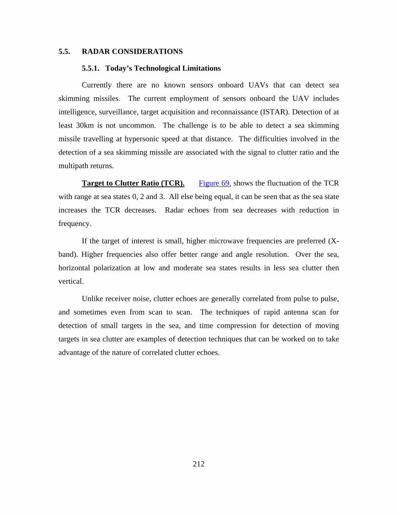
212
5.5. RADAR CONSIDERATIONS
5.5.1. Today’s Technological Limitations
Currently there are no known sensors onboard UAVs that can detect sea
skimming missiles. The current employment of sensors onboard the UAV includes
intelligence, surveillance, target acquisition and reconnaissance (ISTAR). Detection of at
least 30km is not uncommon. The challenge is to be able to detect a sea skimming
missile travelling at hypersonic speed at that distance. The difficulties involved in the
detection of a sea skimming missile are associated with the signal to clutter ratio and the
multipath returns.
Target to Clutter Ratio (TCR). Figure 69. shows the fluctuation of the TCR
with range at sea states 0, 2 and 3. All else being equal, it can be seen that as the sea state
increases the TCR decreases. Radar echoes from sea decreases with reduction in
frequency.
If the target of interest is small, higher microwave frequencies are preferred (X-
band). Higher frequencies also offer better range and angle resolution. Over the sea,
horizontal polarization at low and moderate sea states results in less sea clutter then
vertical.
Unlike receiver noise, clutter echoes are generally correlated from pulse to pulse,
and sometimes even from scan to scan. The techniques of rapid antenna scan for
detection of small targets in the sea, and time compression for detection of moving
targets in sea clutter are examples of detection techniques that can be worked on to take
advantage of the nature of correlated clutter echoes.

213
Figure 69. TCR plot (Range Resolution 3.3m, UAV=5000ft, Missile=30m, X band, (SS
0,2,3))
Multipath. Multiple-input multiple-output (MIMO) techniques have been well
studied in communications offering advantages where multipath environments can cause
fading. Radar waveform rejection of multipath requires that the range resolution cell be
smaller than the range difference (range resolution) between the direct and multipath
echoes. The majority of MIMO radar configurations have focused on multistatic arrays
that have sufficient spatial separation to decorrelate the target’s RCS scintillation. These
networks combine the received data non-coherently to average out the scintillation.
Another form of MIMO radar uses multiple orthogonally coded waveforms from
individual transmitter elements of a phased array which are then combined coherently
upon receive to form multiple beams. This concept holds huge potential and can be
exploited by a swarm of UAVs in the detection of sea skimming missile.
Multi Function Radar. With the miniaturization, lowering cost of
processing and the pressing need for extreme beam agility the goal is to have a radar
which will perform multiple functions in one system. As such it is envisaged that the
Sea state 0
Sea state 2
Sea state 3

214
sensor which will be mounted on the UAVs will be a phased array multi function radar
capable of providing surveillance and tracking a fast moving target.
Key Specifications. For an operating height of 5000ft trying to detect a sea
skimming missile (supersonic speed) travelling at a height of 30m above sea level the
range resolution needed is 3.3m. Using a frequency of 9.3GHz with an aperture diameter
of 2m, the 3dB beamwidth is given by 1.20.
Range Resolution α t2h h 2(1666)(30)ΔR = = = 3.3mR 30000
3-dB Beamwidth 3dBα
λθ °= 1.25 = 1.2d
⎛ ⎞⎜ ⎟⎝ ⎠
τRT
RC 0i 3dB τ
σP 1SNR = TCR = =P σ ΔR(θ )R
Where στ is the RCS of the target
and σ0i is the backscatter coefficient for sea state i (i-0-4)

215
Figure 70. shows a plot of the sea backscatter coefficients as a function of grazing
angle. It can be seen that the sea backscatter coefficient increases as the sea state
increases.
Figure 70. Plot of Sea backscatter coefficients vs Grazing angle
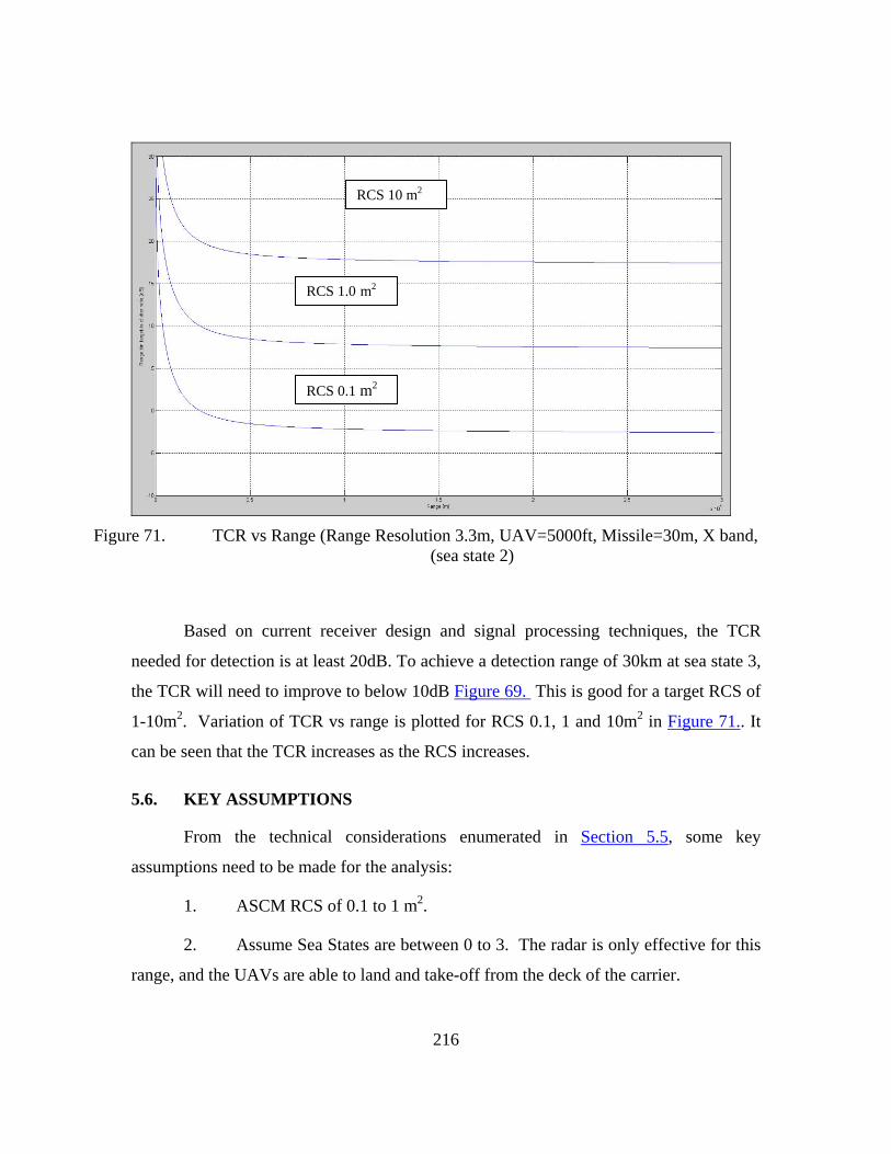
216
Figure 71. TCR vs Range (Range Resolution 3.3m, UAV=5000ft, Missile=30m, X band,
(sea state 2)
Based on current receiver design and signal processing techniques, the TCR
needed for detection is at least 20dB. To achieve a detection range of 30km at sea state 3,
the TCR will need to improve to below 10dB Figure 69. This is good for a target RCS of
1-10m2. Variation of TCR vs range is plotted for RCS 0.1, 1 and 10m2 in Figure 71.. It
can be seen that the TCR increases as the RCS increases.
5.6. KEY ASSUMPTIONS
From the technical considerations enumerated in Section 5.5, some key
assumptions need to be made for the analysis:
1. ASCM RCS of 0.1 to 1 m2.
2. Assume Sea States are between 0 to 3. The radar is only effective for this
range, and the UAVs are able to land and take-off from the deck of the carrier.
RCS 10 m2
RCS 1.0 m2
RCS 0.1 m2

217
3. Detection to Firing Time. The time between detection to firing, a factor
determined by human Observe-Orient-Decide-Act (OODA) cycle, is taken to be a
constant 10 sec in this analysis.
4. Track Handling. A capability to continuously track the incoming ASCM
with sufficient accuracy to guide the interceptor missile(s) from the CVBG to the
incoming ASCM is assumed.
5.7. ANALYSIS METHODOLOGY AND RESULTS
5.7.1. A Two Phase Model
In order to determine the UAV fleet size, modeling was conducted in two phases.
Modeling Phase I derived the number of UAV’s required to ensure sufficient radar
coverage of the circumferential perimeter of the early warning screen. Each position that
is required to be filled by a UAV is termed an aerial picket station, denoted by k.
Modeling Phase II is a discrete event simulation takes Modeling Phase I further by
considering the finite endurance and failure rates of the UAV platform and sensors, and
outputs the UAV fleet size required to support the mission.
5.7.2. Modeling Phase I: Derive Required Number of Aerial Picket Stations
5.7.2.1. Overview
Modeling Phase I is a geometric model formulated to cover the given
perimeter based on a ring of UAVs, assuming each UAV’s detection range as a cookie
cutter with a given effective radius. The model can also be applied for a non-circular
protection pattern, for example when the region in front of the CVBG is given a larger
alert time than that behind the CVBG, the sterns if the expected major threat axis is from
the front. However, in this example, the threat is expected to be omni-directional,
necessitating a circle for the early warning screen.
5.7.2.2. Description
For a given CVBG, with an existing detection radius R, the model
calculates k UAVs, equidistant from each other, in a circle with radius Ruav. As shown in

218
Figure 72., each UAV in the early warning screen is modeled to have a side-scanning
radar with a scanning angle of θ, and a detection radius Rd.
Figure 72. Early Warning Screen of UAVs
Engagement Sequence. The engagement takes place as follows:
1. Enemy missile enters UAV early warning screen perimeter with
speed Vm .
2. Enemy missile stays in UAV detection region for at least Tmin,1 in
order for the UAV to detect the missile (T1). Neighboring radar coverages must overlap
for Tmin,1.
3. Command center at CVBG completes the OODA loop for the
engagement in an additional Tmin,2 from T1. The interceptor missile flies out from the
aircraft battle group and travels at speed Vamm (assume instantaneous acceleration)
towards the incoming enemy ASCM.
4. Interceptor missile engages enemy missile at R. The Command
Center at the CVBG performs a battle damage assessment (BDA) and, if there are

219
surviving ASCMs, proceeds to engage with a second salvo of interceptor missiles, if
necessary.
Geometric Analysis. Based on the geometry of the early warning screen,
k can be determined through the equations that follow based on Figure 73.
Figure 73. Geometric Analysis of Early Warning Screen
Key Variables
k Number of UAVs required
φ Angle between each UAV
Ruav Radius of circle that each UAV orbits around the ABG
Rper Radius of circle for effective detection of the UAV system
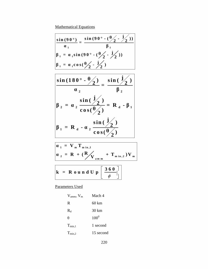
220
Mathematical Equations
1 1
1 1
1 1
jθs in ( 9 0 ° - ( - ) )s in ( 9 0 ° ) 2 2=α β
jθβ = α s in ( 9 0 ° - ( - ) )2 2jθβ = α c o s ( - )2 2
2 2
2 2 d 1
1 d 2
jθs in (1 8 0 ° - ) s in ( )2 2=α β
js in ( )2β = α = R - βθc o s ( )2js in ( )2β = R - α θc o s ( )2
1 m m i n ,1
2 m i n , 2 ma m m
α = V TRα = R + ( + T ) VV
φ⎡ ⎤⎢ ⎥⎣ ⎦
3 6 0k = R o u n d U p
Parameters Used
Vamm, Vm Mach 4
R 60 km
Rd 30 km
θ 1000
Tmin,1 1 second
Tmin,2 15 second

221
5.7.2.3. Results and Sensitivity Analysis
Numerical methods were used to solve for k, yielding k = 15 for the
baseline Rd of 30 km and Tmin,1 of 1 sec. Further sensitivity analysis was conducted to
vary Rd and Tmin,1. Rd was varied from 20 to 40 km, while Tmin given a range of 1 to 4
secs. The results are presented in Table 26. k ranges from a low of 12 to 27. This range
of k is used for Modeling Phase II to determine the UAV fleet size.
1 1.5 2 2.5 3 3.5 4
20 23 24 24 25 26 26 2722.5 20 21 22 22 23 23 24
25 18 19 19 20 20 20 2127.5 17 17 18 18 18 18 19
30 15 16 16 16 16 17 1732.5 14 15 15 15 15 15 16
35 13 14 14 14 14 14 1537.5 12 12 13 13 13 13 14
40 12 12 12 12 12 12 13
Tmin,1
Rd
TABLE 26. VARIATION OF K UAVS WITH RD AND TMIN,1.
5.7.3. Modeling Phase II: Determine Fleet Size
5.7.3.1. Overview
Model II is a discrete event simulation taking the finite endurance and
failure rates of the UAV platform and sensors into consideration when determining the
fleet size. A fleet scheduling methodology is called upon to determine the minimum fleet
size required.
5.7.3.2. Description
In order to have a persistent early warning screen of UAVs, flight
operations will need to take into account several key events. Each UAV has a finite
endurance, and will need to land to refuel and be readied for the next mission (a
“turnaround”, which also includes the necessary preventive maintenance tasks). During
flight, if a failure of a mission critical component occurs, the UAV will need to cut its

222
time of station and return to base to have the failed component fixed or replaced. The
repair requires additional time which consequently extends the turnaround time to be
ready for the UAV’s next mission. The turnaround time will vary with the workload of
the ground-crew and repair times will vary with the complexity of the task. Model II
accounts for both variations. Figure 74. illustrates the operating schedule required to
sustain a single aerial picket station.
Figure 74. Sample Scheduling of UAVs for a Single Aerial Picket Station
5.7.3.3. Formulation
The schedule from Figure 74. is extended to k UAVs (determined in
Model I), and the events were simulated in SimKit using the event graph depicted in
Figure 75.
A description of which is as follows:
1. UAVs are launched at intervals of one hour (the travel time). The
time of launch is recorded and the remaining operation time is calculated to determine if
the UAV will fail during flight on route to the patrolling position.
223
2. Patrolling starts, and another UAV is scheduled to replace the
current UAV.
3. Turnaround (refuel and regular maintenance) is scheduled upon
return to carrier, with the maintenance time assigned randomly from a triangular
distribution.
4. The UAV is ready for launch, with clocked operation hours
recorded.
5. If the UAV encounters a mission critical failure at any point of the
mission, it will immediately return to the carrier for repairs, triggering an immediate
launching of a mission replacement.
6. The repairs are carried out immediately with a random (triangular
distribution) repair time, followed by the turnaround.
7. Repaired UAVs are added to the standby storage with all
parameters reset as in a new UAV.

224
Figure 75. Event Graph for the Scheduling Model in SimKit
Parameters and Variables
• k – number of aerial picket stations from Model I
• s – container representing a spare storage of the ready-to-launch
UAVs in standby
• M – number of UAVs required to support the whole operations
sequence

225
• P – counter to keep track of the number of UAVs in active patrol
mission. (This provided a means to measure the up time of the
detection circle.)
• R – counter to keep track of the total repairs made throughout a
operation cycle
• fT – flight time of a UAV from the launching platform to patrolling
station. (Fixed as flight to position is the radius of the patrolling
circle. Currently, assumed as 113.5km ÷ 217km/h = 0.523hr)
• TD – record of time that the UAV is launched for mission.
• Pt – maximum patrol time. (Calculated based on 46 hours of max
endurance of the UAV and 0.523hr of single way flight time to
patrol position. Pt = 46 – (2x0.523) = 44.954hr)
• Tclocked – Cumulative time that the UAV have operated in flight.
• R1 – Calculation of the remaining time before failure occurs. (This
value is used to determine if UAV will fail during flight to
position. Calculated based on R1 =TTF - Tclocked )
• R2 – Calculation of the remaining time allowed for the rest of the
patrolling mission. (This value is used to determine if UAV will
fail during patrol mission. Calculated based on R2 = TTF - Tclocked –
fT)
• tr – Randomly generated repair time of the UAV on failure.
Assuming a triangle distributed time between a range of 4hours to
8hours with a mode of 5hours.
• tm – Randomly generated maintenance time of the UAV after each
mission completion. Assuming a triangle distributed time between
the range of 0.8hours to 2hours with a mode of 1hr

226
• TTF – The cumulative total time of flight before the UAV
encounters a non-catastrophic failure. Assuming a normal
distribution of mean 200hours and standard deviation of 60.79.
This will provide us a targeted mean time between failure (MTBF)
of 200 to be achieved by 2030 and a 5% probability that the Time
To Fail (TTF) will be below 100hours of operation.
5.7.3.4. Results
Modeling Phase II determined that a fleet size of 21±1 UAVs is required
to achieve the persistent early warning screen, given Rd of 30km and Tmin,1 of 1 sec. This
result is summarized together with sensitivity analysis for Rd of from 20 to 40 km and
Tmin,1 from 1 to 4 sec in Table 27.
Figure 76. shows a surface plot of the same sensitivity analysis, while the
box plots in Figure 77. and Figure 78. show the means and standard deviations of the
fleet size for Tmin,1 of 1 and 4 sec, with Rd ranging from 20 to 40km taken over 1000
simulation runs. The deviations from the mean are small (approximately 1) due to the
fact that the endurance of the platform is long and the system is reliable (less than 5%
failure rate), leading to small variations in the final fleet size. Intuitively, more UAVs are
required if the coverage overlap Tmin,1 is increased.
In conclusion of the analysis and for further discussions of the C2
architecture, a baseline UAV fleet size can be taken to be 21. For a conservative fleet
size estimate, given the uncertainties of the coverage overlap and radar detection range, a
fleet size of 35 can be used.

227
20 30 40
1 30 21 18
2 31 22 18
4 35 24 19
Coverage Overlap
Tmin,1 (sec)
Detection Range Rd (km)
TABLE 27. FLEET SIZE VARIATION WITH DETECTION RANGE AND COVERAGE OVERLAP.
Figure 76. Surface Plot of Variation of Fleet Size

228
Rd= 20km Rd=30km Rd=40km
Tmin,1 of 1 sec
Figure 77. Box Plots of Fleet Size Means and Standard Deviations Size

229
Rd= 20km Rd=30km Rd=40km
Tmin,1 of 4 sec
Figure 78. Box Plots of Fleet Size Means and Standard Deviations Size

230
5.8. COMMUNICATION AND NETWORK ANALYSIS
In this operation scenario, the communications and network (CN) systems need to
fulfill the following requirements:
• Uplink113(UL): Air-to-surface platform
o Data rate: Low, periodic and short
o Traffic Type:
Sensor tracks
Telemetry signals
• Downlink (DL): Surface-to-Air platform
o Data rate: Low, random short-burst
o Traffic Type:
Command & Control signal
• Bi-directional Range: Up to 100km
The current technologies capable of meeting the above requirements are tactical
datalink and SATCOM systems.
Tactical datalinks (e.g. Link 16) were built to support real-time collaboration
between tactical sensor and shooters in the tactical environment. Link 16 operates on
ultra high frequency line-of-sight UHF-LOS band (960-1215MHz). It operates on Time-
Division Multiple Access (TDMA) scheme which offers 1536 time-slots per 12 sec
frame. The time slots in each frame are partitioned into functional groups called NPGs,
e.g. surveillance, air control, fighter-to-fighter net, etc. They are dynamically assigned to
user on-demand based on a predefined format.114
113 This definition is based on Star-topology setup: “Uplink” refers the link from mobile stations to
central base station; “Downlink” refers to the link from central base station to mobile stations. 114 Tadil J: Introduction To Tactical Digital Information Link J And Quick Reference Guide, Fm 6-
24.8/ Mcwp 3-25c/ Nwp 6-02.5/ Afttp(I) 3-2.27, June 30, 2000, http://www.globalsecurity.org/military/library/policy/army/fm/6-24-8/tadilj.pdf (accessed June 4, 2010)

231
To estimate115 the maximum number of sensors that one tactical datalink net can
support, the following assumptions were made:
• Let the average data size of sensor-feed data be D bytes/track;
• For each target track, let the average track update rate be T
tracks/second/missile;
• Let the system throughput capacity of link-16 that is reserved for sensor
feed be Cb bits/sec;
• Let the number of maximum concurrent missile attacks expected be M
missiles;
• There are maximum of 2 sensors covering and airspace at any instant
(overlapped detection zone);
• Assuming there are n sensors operating in the AO in ring orbit, the maximum
number of sensors datalink can support is:
( )
Capacity reserved for sensor data transmission2 M Datarate demand per unit per track detected
( / )2 8 / ( / ) ( / )
bC bit sM bit byte D byte track T track s
n× ×
× × × ×
⎢ ⎥⎢ ⎥⎣ ⎦⎢ ⎥⎢ ⎥⎣ ⎦
<
<
For example, assuming the following values for T, Cb, D, and M; n =15
sensors/net.
• T = 1 track/sec
• Cb = 2400bps
• D = 10bytes/track
• M=1, the number of sensors supported
115 This estimation shall be based on generic perspective, given the fact that the detailed format for
tactical datalink was not available for this study.
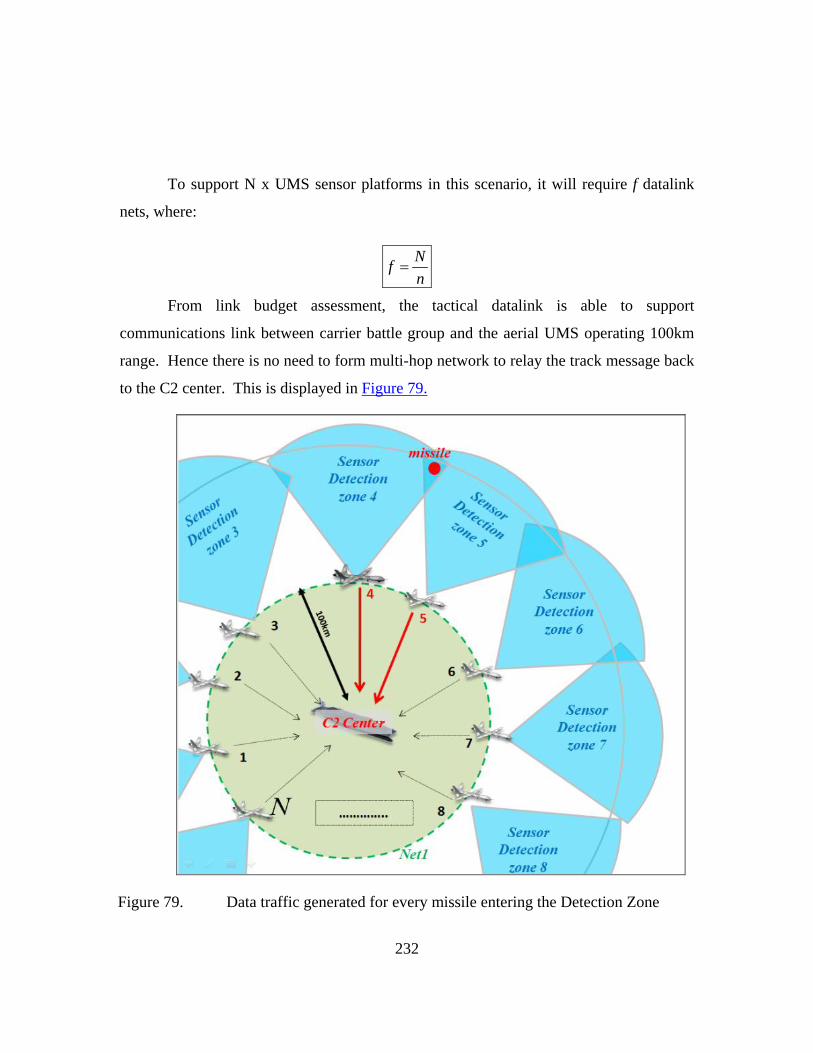
232
To support N x UMS sensor platforms in this scenario, it will require f datalink
nets, where:
Nfn
=
From link budget assessment, the tactical datalink is able to support
communications link between carrier battle group and the aerial UMS operating 100km
range. Hence there is no need to form multi-hop network to relay the track message back
to the C2 center. This is displayed in Figure 79.
Figure 79. Data traffic generated for every missile entering the Detection Zone
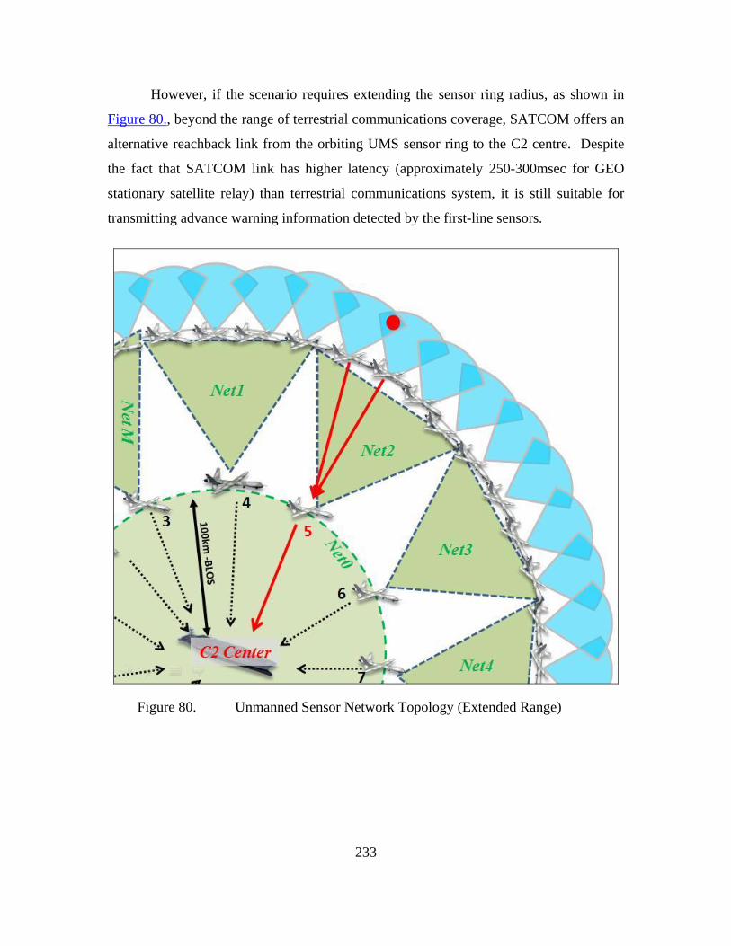
233
However, if the scenario requires extending the sensor ring radius, as shown in
Figure 80., beyond the range of terrestrial communications coverage, SATCOM offers an
alternative reachback link from the orbiting UMS sensor ring to the C2 centre. Despite
the fact that SATCOM link has higher latency (approximately 250-300msec for GEO
stationary satellite relay) than terrestrial communications system, it is still suitable for
transmitting advance warning information detected by the first-line sensors.
Figure 80. Unmanned Sensor Network Topology (Extended Range)

234
5.9. RANGE ASSESSMENT: LINK BUDGET FOR SURFACE-TO-AIR COMMUNICATIONS LINK
The tactical class UAV operates at altitudes of 10,000 feet (3.05km) above mean
sea level (AMSL) for the payload’s ISR capabilities to function optimally within electro-
optical (EO) sensor range. In general, the datalink range is limited by the transmission
power of the UAV’s onboard antenna. Therefore the values of UAV transmission powers
is used as a constraints for link margin calculations. Figure 1 shows the fade margins1
considered at a distance of 100km with transmission powers, Pt of 10, 20, 50 and 100
watts in the line-of-sight (LOS). In the scenario of datalink between the carrier and
UAV, as the distance between them increased the fade margin decreases. At the lowest
transmission power of 10W the fade margin was at 15dB above the minimum threshold.
This suggests that there is sufficient link margin to meet the surface-to-air and air-to-
surface duplex link for a single UAV to carrier scenario.
Lacking the technical specifications of radio transmitter and receiver system, the
link budget calculations were based on the following estimated assumptions:
• RF carrier frequency, fc = 1215MHz. (Link-16 Max frequency for UHF-LOS band)
• Receiver system noise temperature of, Tsys = 410K; • Channel Bit-rate, Rb = 2400bps; • Omni directional antennas with gain, Gt, Gr = 1dBi; • Transmitter Power, Pt = 10W, 20W, 50W, 100W • Digital Signal-to-Noise ratio (assume QPSK @ BER <10-5), Eb/N0, min ≈
10dB (See Figure 2); • Other system losses, Lsys = 3dB;
• Channel Loss Model: Free space path loss model, Lchannel 2
1R
∝ ;
• Boltzmann Constant, k = 231.38 10−× Joules • Speed of Light, c = 83 10−× m/s

235
Link budget formula:
⎛ ⎞ ⎛ ⎞⎜ ⎟ ⎜ ⎟⎝ ⎠ ⎝ ⎠
⎛ ⎞ ⎛ ⎞⎛ ⎞⎜ ⎟ ⎜ ⎟⎜ ⎟ ⎜ ⎟ ⎜ ⎟⎝ ⎠ ⎝ ⎠ ⎝ ⎠
⎛ ⎞⎜ ⎟⎝ ⎠
b b
0 0received min
b b t t r b
0 sys channel sys sysreceived
2c
channel
E EFade Margin = -N N
E R P G G R= S =N kT L L kT
4πf RL =c
The fade margin is plotted against range, R, to extrapolate the link performance
over distance. This graph can be found in Figure 81.
Fade margin represents the received RF power above the minimum threshold
level at a specified bit-error rate (BER) performance. This graph can be found in Figure
82.
In the ideal environment, the received power derived from the link budget is
deemed adequate (given that fade margin > 0dB) to maintain a reliable link (BER < 10-5)
at 100km range. However, in the real environment, the link is subjected to multipath
fading, e.g. the ship superstructure presents multiple reflection surfaces to the radio wave
that is emitted from omni-directional antenna. The random mix of multiple signals
arriving at the receiver via different reflection paths results in random construction and
destruction of RF wave at the receiver. The signal level at the receiver drops when the
resultant waves are destructive. Additional fade margin has to be factored into the link
budget requirement to maintain the desired the link quality. The mitigation methods to
reduce multipath fading are as follow:

236
• Raise the height of the antenna on the ship: This reduces the multipath fading
caused by the planar surfaces of the ship superstructure.
• Multiple-Input Multiple-Output (MIMO) technology: Space-time coding
leverages on spatial diversity and time diversity to reduce the effect of multipath
fading.
• Increase transmission power to increase the fade margin: This approach is limited
by the finite payload capacity of the platform.

237
Figure 81. Fade Margin (dB) is inversely proportional to R2 as the R between Transmitter & Receiver increases

238
Figure 82. Probability of bit error (BER) vs Eb/N0

239
THIS PAGE INTENTIONALLY LEFT BLANK
240
6.0. RESULTS
6.1. SUMMARY OF RESEARCH
A Command and Control Architecture that integrates manned and unmanned
systems will be necessary by 2030. The proposed architectural concept is meant to be a
guide towards realizing this capability. The key will be to develop technology and
doctrine promotes timely, accurate, and appropriate information is available to the
warfighter. This information must cross all mediums to be available to the force
elements that would benefit from that data, whether they are in the local area, or
operating remotely through a global interface.
Integrated Project Teams and specialized Track Teams conducted studies on
several factors, specifically outlining levels of systems autonomy, examining the roles of
humans and machines in systems, examining critical information assurance
considerations, and technical evolution of unmanned vehicle technology.
A functional architecture was developed along with several command and control
architecture products. The functional architecture, described in terms of Boyd’s OODA
Loop, describes the actions that must be taken by the system to conduct operations. The
High Level Operational Concept Graphic illustrated the general operation of the system
and highlighted its features within the 2030 battlespace. The Operational Node
Connectivity Description showed the connectivity and information flow between
operational nodes for Force Protection and Reconnaissance. The Information Exchange
Model showed the typical flow of information between nodes in an operational setting.
Information Exchanges for the system were identified through several matrices. The
Operational Activity Models showed the activities, relationships among activities, inputs
and outputs of the different system nodes. The High Level Conceptual System View
presents a layered approach for building the system.
Architecture concepts were applied to one of the innumerable potential
operational applications for unmanned vehicles. Our model depicted the deployment of
unmanned vehicles to provide the carrier battle group with early detection of an ASCM.

241
The force needed to complete the layout of forces was geometrically evaluated to provide
necessary stations given overlapping coverage, and a discrete event simulation was used
to determine the need for 21 unmanned vehicles to maintain operation of these stations
given the assumed parameters. To relate this model to the architecture capacity, the
relationship between the number of vehicles and network requirements was determined.
6.2. RECOMMENDATIONS
Based on Boyd’s Observe, Orient, Decide and Act (OODA) Loop the Functional
Decomposition of Command and Control was developed to provide (1) the basic
functions required for UMS and (2) an extensive assessment of UMS mission domain.
To satisfy the needs for the battlespace of 2030, recommendations for technology
developments and changes in the organization and joint doctrine were posed.
6.2.1. Actions Needed Prior to 2030
Technology development:
• Radar Receiver Technology - Improvements in detection range and detection
of Sea Skimming Missiles.
• Signal Processing Technology - Improvement in detection range and detection
of Sea Skimming Missiles.
• Improvement in Very Large Scale Integration (VLSI) technology -
Improvement in processing power.
• Materials Research - Light weight materials to reduce the weight of UVs.
• Power Generation - Improvement in power generation per unit weight.
• Prevention of Electromagnetic Interference - EMI will be an issue as more
sensors are packed into an integrated payload. More research is required to
minimize this effect & prevent the jamming of own forces' signals.
• Common Sensor Data Format - With the advent of more sensor types on a
single UMS, a common sensor data exchange format needs to be standardized
in order to optimize the amount of information exchange between unmanned
& manned platforms & prevent incompatibility.

242
• Sensor Fusion- Majority of the sensor fusion is currently done after raw data
are sent back to HQ. An improvement in digital signal processing speed will
allow such sensor fusion to take place at the front end (UMS). This will
minimize the amount of sensor data to be sent back & hence reduce
bandwidth requirements.
• Increase the Size of Imaging Array—to increase the capacity of EO sensors to
have sufficiently broad fields of view and resolution. This will then allow
detection of entities at long ranges so that sophisticated image interpretation
techniques can perceive and “understand” the key elements in the
environment.
Required organizational actions:
• Generate an official Joint Operational Concept in accordance with Chairman
Joint Chief of Staff Instruction 3010.02B, Joint Operations Concept
Development Process.
• Develop doctrine, in coordination with coalition forces, for operations
involving integrated manned and unmanned systems.
• Parallel technology development with coalition forces.
• Promote common standards for interoperability between US and allied
nations.
• Encourage industry to develop common control console for unmanned
vehicles of all mediums.
• Invest in information systems personnel to develop a technically savvy force.
• Continue to improve the transfer of data through enhancements to tactical data
networks.

243
6.3. FUTURE AREAS OF STUDY
Many of the concepts for future battlespace engagements are in their infancy
today. This research project helped identify some of these concepts. Below are listed a
few that were deemed essential next steps to further the interactions between unmanned
and manned vehicles as well as their overall joint operations.
• Optimal balance between manned and unmanned systems to accomplish
future missions.
• Self healing, self forming networks.
• Required organizational changes in the DoD to manage the increase usage of
unmanned systems.
• Logistics required to support future manned and unmanned system force
structure.
• Maintenance concept for future unmanned force.
• Suitability of unmanned systems being deployed from the expected military
platforms of 2030.
• Legal issues arising from use of unmanned vehicles.

244
7.0. GLOSSARY, ACRONYMS, AND ABBREVIATIONS
7.1. GLOSSARY
Architecture: “a framework or structure that portrays relationships among all the
elements of the subject force, system, or activity.”116
Capability: the ability to execute a specified course of action. (A capability may or may
not be accompanied by an intention)
Capability Based Assessment: the portion of the JCIDS analysis that identifies
capability and supportability shortfalls, gaps, and redundancies on specific capability
needs. CBAs generally consist of three parts: the Functional Area Analysis (FAA),
Functional Needs Analysis (FNA) and the Functional Solution Analysis (FSA). Results
of FAA and FNA are documented in the Joint Capabilities Document.
Capstone: the crowning achievement, point, element, or event.117
Collection Management Authority: Constitutes the authority to establish, prioritize,
and validate theater collection requirements, establish sensor tasking guidance, and
develop theater collection plans.
Collection Operations Management: The authoritative direction, scheduling, and
control of specific collection operations and associated processing, exploitation, and
reporting resources.
Condition: a variable of the operational environment that may affect task performance.
Physical conditions pertain to the material environment: weather, climate, geography,
and terrain. Military conditions are those characteristics of the equipment upon which the
performance of desired military functions depend
116 Department of Defense, Department of Defense Dictionary of Military and Associated Terms, Joint Publication 1-02 (12 April 2001, as amended through 19 August 2009).
117 Capstone, available from http://dictionary.reference.com/, accessed 17 February 2010.

245
Data: Data will incorporate the following items under the name “Data”: Data, Voice,
and Video information that is transmitted between a Control Center and an Unmanned
System.
Discipline: a branch of knowledge; as used in this document, discipline refers to a
particular type of intelligence: HUMINT, IMINT, SIGINT, MASINT, OSINT, etc.
Domain: a location environment; as used in this document, domain refers to either
maritime, aerospace, terrestrial, etc.
Intelligence Community: a federation of executive branch agencies and organizations
that conduct intelligence activities necessary for conduct of foreign relations and
protection of national security including: CIA, DIA, NRO, NSA, NGA, State Dept,
Treasury, DHS, DEA, FBI, Energy, Service Intel Organizations (Army, Navy, Air Force,
Marines, Coast Guard).
Intelligence, Surveillance, and Reconnaissance (ISR): an activity that synchronizes
and integrates the planning and operation of sensors, assets, and processing, exploitation,
and dissemination systems in direct support of current and future operations, an
integrated intelligence and operations function.
Integrated:
1. combining or coordinating separate elements so as to provide a harmonious,
interrelated whole: an integrated plot; an integrated course of study
2. organized or structured so that constituent units function cooperatively: an
integrated economy.
3. having, including, or serving members of different racial, religious, and ethnic
groups as equals: an integrated school.118
Integrated Management: Creation of a military force that operates by engaging as a
whole through processes including, but not limited to: strategic planning, setting
118 Integrated, available from http://dictionary.reference.com/, accessed 17 February 2010.
246
objectives, managing resources, deploying human and technical assets needed to achieve
objectives, and measuring results.
ISR Enterprise: Those defense organizations, resources, and personnel assigned
responsibilities for executing any part of the intelligence mission. The ISR Enterprise
includes a core set of organizations and resources that have intelligence as a primary
function. The ISR Enterprise may include other resources providing information of
intelligence value under command and control arrangements specified by the Combatant
Commander, JFC, or subordinate/component commander.
ISR Resource: Any asset that collects, processes, exploits, analyzes, or manages data
that is used within the intelligence process. These resources are not necessarily
"intelligence" resources, and may have a primary mission other than intelligence.
Joint Force Commander: A general term applied to a Combatant Commander, sub-
unified commander, or joint task force commander authorized to exercise combatant
command or operational control over a joint force.
Low Density/High Demand: LD/HD assets are defined as certain limited assets/forces
with unique mission capabilities stressed by continual high OPTEMPO because of JFC
requirements. Assets are governed by steady-state and surge capabilities defined in the
Global Military Force Policy (GMFP). Steady-state is defined as the maximum peacetime
deployment capability that can be sustained indefinitely with no adverse impact. Surge is
defined as an additional level of deployment that can be sustained for a limited period
with some adverse impact. (After a period of surge, a defined recovery period at or below
steady-state is required.) The SECDEF must approve any deployment that forces an
LD/HD asset into surge status.
Persistence: the length of time a sensor can provide continuous coverage of a location,
target, or activity of interest. The JFC's desire for persistence is founded upon his
inability to satisfy CCIRs, PIRs, or EEIs, with the current ISR Enterprise due to problems
or obstacles generated by friendly and/or adversary actions or capabilities. What

247
constitutes persistence varies significantly dependent upon JFC mission objectives,
operating environment, and target type.
Standard: quantitative and qualitative measures for specifying the levels of performance
of a task.
System: is a “set of components (subsystems, segments) acting together to achieve a set
of common objectives via the accomplishment of a set of tasks.”119
Systems Engineering: Systems Engineering is an interdisciplinary approach and means
to enable the realization of successful systems. It focuses on defining customer needs and
required functionality early in the development cycle, documenting requirements, then
proceeding with design synthesis and system validation while considering the complete
problem:
Operations Cost & Schedule
Performance Training & Support
Test Disposal
Manufacturing
Systems Engineering integrates all the disciplines and specialty groups into a team effort
forming a structured development process that proceeds from concept to production to
operation. Systems Engineering considers both the business and the technical needs of all
customers with the goal of providing a quality product that meets the user needs120
Systems Architecture: An architecture deals with a top-level system structure
(configuration), its operational interfaces, anticipated utilization profiles (mission
119 Buede, Dennis M., The Engineering Design of Systems: Models and Methods. John Wiley &
sons, New York, NY, 2000, p. 440. 120 Systems Engineering, available from https://www.incose.org, accessed 14Jan 2010

248
scenarios), and the environment within which it is to operate; then it describes how these
various requirements for the system interact.121
Task: an action or activity (derived from an analysis of the mission and concept of
operations) assigned to an individual or organization to provide a capability.
7.2. ACRONYMS
AAI Aircraft Armaments, Inc
ACN Aerial Communications Network
AIP Air Independent Propulsion
AO Area of Operations
AoA Analysis of Alternatives
AFO Advance Force Operations
AFRL Air Force Research Laboratory
ALFUS Autonomy Levels for Unmanned Systems
AOE Automated Ordnanace Excavator
AOR Area of Responsibility
ASCM Anti-Ship Cruise Missile
ASTM American Society of Tests and Materials
ATDC After Top Dead Center
AUV Autonomous Unmanned Vehicle
AUVS Association for Unmanned Vehicle Systems
AUVSI Association for Unmanned Vehicle Systems International
121 Blanchard, 2006.

249
BA Battlespace Awareness
BAE British Aerospace Systems
BDA Battle Damage Assessment
BFT Blue Force Tracking
BIT Built in Test
BLOS Beyond Line of Sight
BPAUV Battlespace Preparation Autonomous Undersea Vehicle
BPD Barrels per Day
BTDC Before Top Dead Center
BULS Bottom (UUV) Localization System
C2 Command and Control
C2AFT Command and Control Architecture Task Force
C3 Command, Control, and Communications
C4 Command, Control, Communications and Computers
C4I Command, Control, Communications, Computers and Intelligence
C4ISR Command, Control, Communications, Computers and Intelligence, Surveillance, and Reconnaissance
CARACaS Control Architecture for Robotic Agent Command and Sensing
CAT Crew-Integrated and Automation Test-bed
CBA Capabilities Based Assessment
CBP Capabilities Based Planning
CBR Chemical, Biological, Radiological
CCDD Cover, Concealment, Deception, Denial
CCIR Commander’s Critical Information Requirements

250
CCJO Capstone Concept for Joint Operations
CDS Common Data Standards
CES Commander’s Estimate of the Situation
CIA Central Intelligence Agency
CIA Confidentiality, Integrity, and Availabiity
CIO Chief Information Officer
CN Communications Network
CNS Communications, Network, and Sensors Track
COA Course of Action
COBRA Combine Operations Battlefield Robotic Asset
COCOM Combatant Command
COIN Common Operator Interface Navy
COLREGS Coast Guard International Rules for Avoiding Collisions at Sea
CONOPS Concept of Operations
COTS Commercial Off the Shelf
COUGAR Cooperative Unmanned Ground Attack Robots
CSAR Combat Search and Rescue
CVBG Carrier Battle Group
CVC Constant Volume Combustion
D.Sc. Doctor of Science
DAMA Dynamic Assigned Multiple Access
DARPA Defense Advanced Reaserch Projects Agency
DBA Dominant Battlespace Awareness
DEA Drug Enforcement Agency
251
DHS Department of Homeland Security
DIA Defense Intelligence Agency
DNI Director of National Intelligence
DoD Department of Defense
DoDD Department of Defense Directive
DOE Department of Energy
DOS Department of State
DOTMLPF Doctrine, Organization, Training, Materiel, Leadership and Education, Personnel, Facilities
EC Environmental Complexity
EO Electro-Optical
EOD Explosive Ordnance Disposal
EEI Essential Elements of Information
EM Electromagnetic
EPA Environmental Protection Agency
ESM Electronic Support Measures
EW Electronic Warfare
F-T Fischer-Tropsch
FA Force Application
FAA Functional Area Analysis
FAA United States Federal Aviation Administration
FBI Federal Bureau of Investigation
FCB Functional Capabilities Board
FFBD Functional Flow Block Diagram
FINDER Flight Inserted Detection Expendable for Reconnaissance

252
FL Focused Logistics
FM Force Management
FNA Functional Needs Analysis
FOPEN Foliage Penetration
FSA Functional Solution Analysis
GH GLOBAL HAWK
GMFP Global Military Force Policy
GSEAS Naval Postgraduate School Graduate School of Engineering and Applied Sciences
GSOIS Graduate School of Operations and Information Sciences
GWOT Global War on Terrorism
HADR Humanitarian Assistance Disaster Relief
HALE High Altitude Long Endurance
HAPS High Altitude Platform Station
HDF High Definition Format
HDW Howaldtswerke-Deutsche Werft
HECC High Efficiency Clean Combustion
HFE Hidden Field Equations
HI Horizontal Independence
HI Human Integration
HLS Homeland Security
HMCDM Human Machine Collaboration Decision Making
HQ Headquarters
HRI Human Robot Interface
HUMINT Human Intelligence

253
HVU High Value Unit
HWV Heavy Weight Vehicle
IA Information Assurance
IC Intelligence Community
ICAO International Civil Aviation Organization
IED Improvised Explosive Devices
IFF Identification Friend or Foe
IFR Instrument Flight Rules
IMINT Imagery Intelligence
IPL Integrated Priority List
IPR In-Process Review
IPT Integrated Project Team
IR Infared
ISAR Inverse Synthetic Aperature Radar
ISR Intelligence, Surveillance, and Reconnaissance
ISTAR Intelligence, Surveillance Target Acquisition and Reconnaissance
I&W Indications and Warning
JAUS Joint Architecture for Unmanned Systems (NASA developed used on the Mars Rovers. Intelligent Autonomy Engine)
JCA Joint Capability Area
JFC Joint Force Commander
JIATF Joint Interagency Task Force
JIC Joint Integrating Concept
JIPOE Joint Intelligence Preparation of the Operational Environment

254
JOpsC Joint Operations Concepts
JP Joint Publication
JPL Jet Propulsion Lab
JROC Joint Requirements Oversight Council
JTF Joint Task Force
LBSAUV Littoral Battlespace Sensing Autonomous Underwater Vehicle
LCS Littoral Combat Ship
LD/HD Low Density/High Demand
LiFePO4 Lithium Iron Phosphate
LOC Lines of Communication
LOE Limited Objective Experiment
LPD Low Probabilty of Detection
LPI Low Probabilty of Interference
LWV Light Weight Vehicle
M-HLS/D Maritime-Homeland Security/Defense
MANET Mobile Adhoc Network
MASINT Measures and Signature Intelligence
MATILDA Mesa Associates’ Tactical Integrated Light-Force Deployment Assembly
MAV Micro Air Vehicle
MC Mission Complexity
MCM Mine Counter Measures
MCO Major Combat Operations
MDARS Mobile Detection, Assessment and Response System

255
MEDAL Mine Warfare and Environmental Decision Aids Library
MEDAL-EA Mine Warfare and Environmental Decision Aids Library - Enterprise Architecture
MESF Maritime Expeditionary Security Force
MIMO Multiple Input Multiple Output
MIW Mine Warfare
MLS Multi-level Security
MOE Measures of Effectiveness
MOLLE Modular, Light Weight, Load Carrying Equipment
MOOTW Military Operation Other Than War
MOP Measures of Performance
MOVES Modeling, Virtual Environments, and Simulation Institute Naval Postgraduate School, Monterey, CA, USA.
MTBF Mean Time Between Failures
MTRS Man Transportable Robotic System
N8F Director of Warfare Integration
N-UCAS Navy-Unmanned Air Combat System
NARPV National Association of Remotely Piloted Vehicles
NASA National Aeronautical and Space Agency
NATO North Atlantic Treaty Organization
NAVAIR Naval Air Systems Command
NCE Network Centric Environment
NCOE Network Centric Operating Environment
NECC Naval Expeditionary Combat Command
NGA National Geospatial Intelligence Agency

256
NiMH Nickel Metal Hydride
NOAA National Oceanographic and Atmosphere Administration
NPS Naval Post Graduate School, Monterey, California, USA
NRL Naval Research Lab
NRO National Reconnaissance Office
NSA National Security Agency
NSAM Net-Centric Sensor Analysis for MIW
NUS National University of Singapore
NWDC Naval Warfare Development Group
OMTF Operations Research and MOVES Task Force
ONR Office of Naval Research
ONIR Overhead Non-imaging Infrared
OODA Observe, Orient, Decide, and Act
OPE Operational Preparation of the Environment
OPNAV Office of the Chief of Naval Operation
OPSIT Operational Scenario
OPTEMPO Operating / Operations Tempo
OR Operations Research
OSINT Open Source Intelligence
OV Operational View
PDE Pulse Detonation Engine
PEM Polymer Electrolyte Membrane
PEO Program Executive Office
PIR Prioritized Intelligence Requirement
PLAN People’s Liberation Army Navy (China)

257
PMA Post Mission Analysis
PMA Program Manager Air
PMS Program Manager Surface
PNT Positioning, Navigation, and Timing
POTUS President of the United States
PRC People’s Republic of China
PWBS Project Work Breakdown Structure
R & D Research and Development
RCS Radar Cross Section
REDCAR Remote Detection, Challenge, and Response System
RF Radio Frequency
RPV Remotely Piloted Vehicle
RJ RIVET JOINT
ROE Rules of Engagement
ROMO Range of Military Operation
RONS Remote Ordnance Neutralization System
RTB Return to Base
S & T Science and Technology
SAR Search and Rescue
SAR Synthetic Aperature Radar
SATCOM Satellite Communications
SECDEF Secretary of Defense
SEAL Sea, Air, and Land
SCI Sensitive Compartmented Information
SD Strategic Deterrence
258
SE Systems Engineering
SEA Systems Engineering and Analysis
SEMP Systems Engineering Management Plan
SEP Systems Engineering Plan
SIGINT Signals Intelligence
SJFHQ Standing Joint Force Headquarters
SO Stability Operations
SOF Special Operating Forces
SRR Short Range Radar
SSOC SEA-16 Organizing Committee
SSTR Security, Stabilization, Transition and Reconstruction
STANAG Standardized Agreement
SV Systems View
TCP/IP Tactical Communication Protocol/Internet Process
TCR Target Clutter Ratio
TDSI Temasek Defence Systems Institute
TOC Tactical Operations Center
TPED Tasking, Processing, Exploitation, and Dissemination
TREAS Department of the Treasury
TSC Theater Security Cooperation
TTF Time to Failure
UAV Unmanned Aerial Vehicle
UGV Unmanned Ground Vehicle
UJTL Universal Joint Task List
UMS Unmanned Systems
259
UNCLOS United Nations Covention on the Laws of the Sea
UOSV Unmanned Outer Space Vehicle
USA United States Army
USAF United States Air Force
USMC United States Marine Corps
USN United States Navy
USCG United States Coast Guard
USD (I) Undersecretary of Defense for Intelligence
USSOCCOM United States Special Operations Command
USSV Unmanned Sea Surface Vehicle
USV Unmanned Surface Vehicle
UUV Unmanned Underwater Vehicle
UV Unmanned Vehicle
UXO Unexploded Explosive Ordnance
UWB Ultra Wide Band
VPOTUS Vice President of the United States
VTC Video Tele-Conference
WBS Work Breakdown Structure
WMD Weapons of Mass Destruction
WWI World War 1
WWII World War 2

260
7.3. ABBREVIATIONS
CDR Commander
COL Colonel
CPT Captain
MAJ Major
ME4 Engineer (Singaporean Military Rank)
ME5 Senior Engineer (Singaporean Military Rank)
LT Lieutenant
LTC Lieutenant Colonel
LTJG Lieutenant Junior Grade
RADM Rear Admiral
USA United States of America

261
THIS PAGE INTENTIONALLY LEFT BLANK

8.0. LIST OF REFERENCES
1. Blanchard, Benjamin S. and Wolter, J Fabrycky, Systems Engineering and
Analysis, 4th Edition, Pearson Prentice Hall, Upper Saddle River, NJ, 2006.
2. U.S. Department of Defense, Joint Publication 3-30. Command and Control for
Joint Air Operations. 12 January 2010.
3. U.S. Department of Defense, FY2009-2034 Unmanned Systems Integrated
Roadmap, Pentagon, Washington, DC, April 2009.
4. Huang, Hui-Min, “Autonomy Levels for Unmanned Systems (ALFUS)
Framework, Volume I: Terminology”, Intelligent System Division, National
Institute of Standards and Technology, Sept 2004.
5. Inagaki, T. Human-Machine Collaboration for Safety and Comfort. Presented to
ENRI International Workshop on ATM/CNS. 2009. p. 1.
6. Buede, Dennis, M, The Engineering Design of Systems New York: John Wiley &
Sons, Inc., 2000.
7. U.S. Department of Defense. MIL-HDBK-46855A (Human Engineering Program
Processes and Procedures). 17 May 1999.
8. Price, H. E. The Allocation of Functions in Systems. Human Factors. Vol 27, No.
1.1985.
9. Malasky, Jeremy S. Human Machine Collaborative Decision Making in a
Complex Optimization System. 12 May 2005.
10. Elizabeth Haubert Joseph , Joseph Tucek , Larry Brumbaugh , William Yurcik,
“Tamper-Resistant Storage Techniques for Multimedia Systems,” In IS&T/SPIE
International Symposium Electronic Imaging / Storage and Retrieval Methods
and Applications for Multimedia. 2005.
11. U.S. Department of Defense, Joint Publication 1-02, DOD Dictionary of Military
and Associated Terms, October 2009.

263
THIS PAGE INTENTIONALLY LEFT BLANK

264
APPENDIX A NAVAL EXPEDITIONARY COMBAT COMMAND (NECC) RESEARCH
A.1. OVERVIEW OF NECC
A.1.1. Mission Overview
Figure 83. NECC Mission122
122 NECC Force Capabilities Fact Sheet. Navy Expeditionary Combat Command. Accessed
20May2010.

265
A.1.2. Force Capabilities
There are ten primary force capabilities which are managed by NECC:
• Riverine
• Naval Construction (Seabees)
• Explosive Ordnance Disposal (EOD)
• Maritime Expeditionary Security Force (MESF)
• Expeditionary Intelligence
• Expeditionary Logistics
• Maritime Civil Affairs
• Security Force Assistance
• Combat Camera
• Expeditionary Combat Readiness
A.2. SCOPING FORCE CAPABILITIES FOR ANALYSIS
The SEA-16 tasking statement originally proposed that the project focus the
development of a joint systems concept and supporting architecture to integrate
unmanned vehicles in the Navy fleet structure, using the NECC Mission Statement
shown in Figure 83., and focused on NECC missions.123 Initial research made it
apparent that the project would have to be scoped to a limited number of the force
capabilities.
NECC representatives discussed some initial needs in a video tele-conference
(VTC) on 06 November 2009. Mr. Jim Fowler and CDR Glenn Allen of NECC met
with the SEA-16 cohort, Professor Gary Langford (Thesis Advisor), RADM (ret) Rick
Williams, and CAPT (ret) Chuck Calvano to identify the preliminary areas of focus and
state their organizational needs with regards to these capability areas, as shown in Figure
84. Explosive Ordnance Disposal (EOD), Riverine Forces, and Maritime Expeditionary
123 SEA-16 CAPSTONE PROJECT OBJECTIVES, 03 September 2009

266
were chosen to be those areas of study. These three areas were assessed to benefit the
most from the successful implementation of UMS in the near term. Each area was
assigned to an Integrated Project Team for research and assessment. The products of
each of these areas are presented in Section A.3.
Figure 84. Stated Needs of NECC
A.3. CONTEMPORARY ANALYSIS OF SELECTED NECC CAPABILITIES
A.3.1. Riverine Force Analysis
A.3.1.1. Organization
• Riverine Group One
• Riverine Squadron 1 (RIVRON 1 >100 sailors) Deployed in Iraq
from Apr – Oct 07
Stated Needs of NECC o Explosive Ordnance Disposal
Need a man-portable human extraction vehicle
Explore mission delegation to UVs to counter manning issues.
o Riverine Forces
Desire a UV that meets size limitations to be launched and
recovered from manned platforms
Possible interest in unmanned RHIB (either 7m or 11m)
o Maritime Expeditionary Security Force
Manning requirements extensive - could evolve tasking to UVs.
Reduce risk to personnel in hostile security environments.
Need ability to increase surveillance capabilities in high volume
shipping areas to reduce small craft threat operating in close
proximity to large merchants.

267
• Riverine Squadron 2 (RIVRON 2 >130 sailors) Deployed in Iraq
from Oct 07 – Apr 08
• Riverine Squadron 3 (RIVRON 3 >150 sailors) Deployed in Iraq
from Apr 08 – Oct 08
• Each squadron commanded by O-5
• Each squadron is self sufficient
• Squadrons may act individually or in a joint environment or with
coalition partners
A.3.1.2. Missions
• Conduct Maritime Security Operations
o Establish control of rivers in specific regions for specific
periods of time
o Protect lines of communication
o Deny the enemy commercial and military use of rivers
o Establish an area of operations for power projection ashore
o Protect naval logistic support to forward deployed forces
• Positively interact with local population to win public support
o Patrol and Interdiction
o Protect friendly lines of communication
o Deny hostile forces the use of waterways
o Collect intelligence information
o Perform security missions
o Enforce population and resources control

268
o Locate and destroy hostile forces, bases, and supplies
within riparian area
• Anti-Piracy
o Employ Riverine craft to deny resources to an enemy and
prevent piracy of pure criminal intent
o Persistent presence to deter piracy
• Law Enforcement
o Boarding teams to board and search indigenous watercraft
o Enforce population and resource control measures
o Collect intelligence information
o Protect critical infrastructure
A.3.1.3. Operations
• Riverine area control
o Protect critical infrastructure along river
o Provide secure area to conduct military operations
o Support civil affairs efforts along or nearby river
• Interdiction of river lines of communication
o Impede, disrupt, eliminate enemy personnel and supply
movement on rivers
• Fire support
o Provide fire support with crew service weapons
• Insertion and extraction of conventional land forces
o Insert between platoon and company size unit
• Theater Security Cooperation
269
o Primary employment of Riverine forces during peacetime
o Garner trust and cooperation of coalition nations
A.3.1.4. Operational Capabilities
• Command and Control
• High Speed and Mobility
• Firepower
• Fire support
• Intelligence and Surveillance
• Visit, Board, Search, and Seizure
• Insertion and Extraction of Conventional Ground Forces
• Self Defense
• Survivability
• Expeditionary Logistics and Sustainment
• Maintainability and Reliability in Expeditionary Environment
• Medical Treatment and Evacuation
• Rapidly Deployable
• Support to Psychological Operations and Civil Military
Operations
• Information Operations Support
• Support to Other Military Operations
• Training of Partners and Coalition Forces
• Aviation Support
• UMS support

270
• Fire Support and Forward Observers
A.3.1.5. Operational Limitations
• Small units that cannot sustain during high intensity missions
• Can only gain local control of river where actively patrolling
• Limited fire power (need fire support)
• Cannot conduct direct combat against a large organized armed
force
• Situational awareness (need ISR support)
A.3.1.6. Environment
• Rivers, Deltas, Harbors, Reservoirs, Lakes
• Riverine Classifications
o Type I: One or more major rivers with branches of
numerous smaller streams, canals, paddies that present on
obstacle, but are not LOCs
o Type II: Several major waterways in addition to extensive
network of small rivers, canals, irrigation ditches that
present an obstacle , but are LOCs.
o Type III: Several major waterways in addition to
extensive network of rivers, canals, irrigation ditches that
do not present an obstacle and are LOCs.
A.3.1.7. Threats
• Expected to operate against up to a Level II threat
• Many threats exist, including:
o Water based mines

271
o Attack swimmers
o Direct Fires
o Indirect Fires
o Suicide bombers and other terrorist activities
o Criminals
A.3.1.8. Utilization of UMS
• USVs and UUVs used to support force in close space to conduct
search and surveillance
• UAVs provide persistent search and surveillance,
communications relay, targeting
• UAVs extend and improve Maritime Domain Awareness in
riparian environment
• Use drives up operational tempo of small force and reduces size
of reaction force
• Riverine Tactical Operation Center utilizes UV images to increase
situational awareness
A.3.2. Explosive Ordnance Disposal Analysis
A.3.2.1. Organization124
• Groups - There are two EOD Groups: EODGRU ONE in San Diego,
California (Naval Amphibious Base Coronado), and EODGRU TWO at
Norfolk, Virginia (Naval Amphibious Base Little Creek).
• Mobile Units - Each Group has readiness responsibility for several
subordinate EOD Mobile Units (EODMU). EODMUs are trained and
proficient in the use of various small arms and unit tactics for the
124 NECC “EOD Fact Sheet”
http://www.public.navy.mil/usff/necc/Documents/04_EOD_FactSheet.pdf

272
prosecution of their core mission skill sets in a combat environment and
for seamless integration with Navy and Army Special Operations
Forces, and Marine Corps Expeditionary Units.
• Company/Platoons and Detachments - EOD Mobile Units are
responsible for several shore-based EOD Detachments supporting key
naval installations. EODMUs have readiness responsibility for
deployable Mine Countermeasures Platoons (EOD MCM Platoons),
multi-mission Mobile Company/ Platoons (EOD MOB
Company/Platoons), and Marine Mammal System Companies (MMS
Companies).
• Mobile Diving and Salvage - EOD is also organized into ready units of
specialized dive teams that conduct harbor and waterway clearance,
emergent underwater repairs, and salvage operations in all
environments In depths up to 300 feet.
• Training and Evaluation - Specialized units located on both coasts
train all EOD forces, develop and evaluate EOD tools, tactics, and
techniques in preparation to deploy.
Marine Expeditionary force is in direct operational control of NECC
EOD assets. These assets fall below the regiment level of a Ground Division for both
operations and support.
• MEF
o Division (Ground)
Regiment
• EOD Assets
o Combat Service Support Group (CSSG)
Logistics Regiment
• EOD Assets
EOD Assets are often two to four man teams. Up to two teams are
assigned to a battalion and in each regiment there up to four battalions.

273
Figure 85. EOD Team Deployment
A.3.2.2. Mission125
• EOD personnel are highly trained, skilled warriors who are
experts in explosives, diving, parachuting, weapons, and small
unit tactics
• Render safe all types of explosive hazards, including conventional
ordnance, improvised explosive devices, and Weapons of Mass
Destruction (chemical/biological, nuclear, and radiological
weapons)
• Conduct clandestine operations either independently, or as part of
a larger combatant force
• Support the most elite units of U.S. Special Operations Command
(USSOCOM), to include direct action support of Navy SEALs
125 NECC “EOD Fact Sheet”
http://www.public.navy.mil/usff/necc/Documents/04_EOD_FactSheet.pdf

274
and Army Special Forces
• Conduct demolition of hazardous munitions, pyrotechnics, and
retrograde explosives using detonation and burning technique
• Support military and civilian law enforcement agencies by
analyzing and handling foreign and domestic explosives
• Work with the U.S. Secret Service and the U.S. State Department,
helping to protect the President of the United States (POTUS),
Vice President (VPOTUS), as well as foreign officials and
dignitaries
• Support the U.S. Department of Homeland Security, U.S.
Customs Office, and the FBI as well as state and local authorities
A.3.2.3. Concept of Operations
In Figure 86 an example of when EOD is used. An infantry patrol
visually detects an explosive device. Regional battlespace commander is then notified
and they deploy an EOD team to interdict. EOD ensures the battlespace commander is
apprised of the situation and this information is also passed on to Theatre Command
Center.

275
RegimentalBattle SpaceCommander
EOD(Land)
IED
TheatreCommand
Center
Intelligence Source
Drone
Jammer
Visual feedback(for control)
DeployUnmanned System
(Ground-zero 1m)
Visual & Update
DeployEOD Team
Command(via CCIS)
Jam Receiver
Infantry(Land)
Figure 86. EOD Land CONOPS
A.3.2.4. Operational Limitations
• Rely on accurate intelligence to avoid unnecessary casualties.
• Can only gain local control of river where actively patrolling
• Need support personnel to protect them during operations
• Situational awareness (need ISR support)

276
A.3.2.5. Environment
• EOD personnel are trained to operate in all land and sea
environments. The can be inserted by air, land or sea.
A.3.2.6. Threats
• Many threats exist, to EOD units beside the ordnance being
disposed of the threats include:
o Snipers
o Proximity mines
o Direct Fires
o Indirect Fires
o Suicide bombers and other terrorist activities
o Incorrect assessment of ordnance disposal
A.3.2.7. Utilization of UMS
• UMS’s are used to support to conduct search and disarmaments
• UMS’s extend EOD’s safety and longevity during missions
• EOD personnel also use UV images to increase situational
awareness

277
RegimentalBattle SpaceCommander
EOD(Land)
IED
TheatreCommand
Center
Intelligence Source
Drone
Jammer
Visual feedback(for control)
DeployUnmanned System
(Ground-zero 1m)
Visual & Update
DeployEOD Team
Command(via CCIS)
Jam Receiver
Infantry(Land)
Figure 87. EOD Land CONOPS
A.3.3. Maritime Expeditionary Security Force Analysis
A.3.3.1. Organization
• Maritime Expeditionary Security Group (MESG)
o 2 Active Groups
• Maritime Expeditionary Security Squadron (MSRON)
o 1 Active Squadron
o 5 Blended Active/Reserve Squadrons
o 4 Reserve Component Squadrons
• Command and Control Divisions (C2DIV)

278
o 2 Active Component Units
o 7 Reserve Component Units
• Boat Divisions (BOATDIV)
o 3 Active Component Units
o 8 Reserve Component Units
o 3 Blended Active/Reserve Units
• Security Divisions (SECDIV)
o 6 Active Component Units 10 Reserve Component Units
• Helo, Visit, Board, Search and Seizure Detachments
(HVBSSDET)
o 2 Active Component Units
A.3.3.2. Mission Decomposition
“MESF’s primary mission is force protection. Anti-Terrorism Force
Protection (ATFP) missions include harbor and homeland defense, coastal surveillance,
and special missions. Units conduct force protection of strategic shipping and naval
vessels operating in the inshore and coastal areas, anchorages and harbors, from bare
beach to sophisticated port facilities. Specialized units work together with Maritime
Expeditionary Security Squadron (MSRON) staffs providing intelligence and
communications. MESF units deploy worldwide to detect, deter, and defend an area,
unit, or High Value Asset.”126
126 MESF Fact Sheet. Navy Expeditionary Combat Command. Accessed 13January 2010.
http://www.necc.navy.mil/NECC%20Fact%20Sheets/00195_NECC_SubCom_MESF_FactSheet_2.pdf
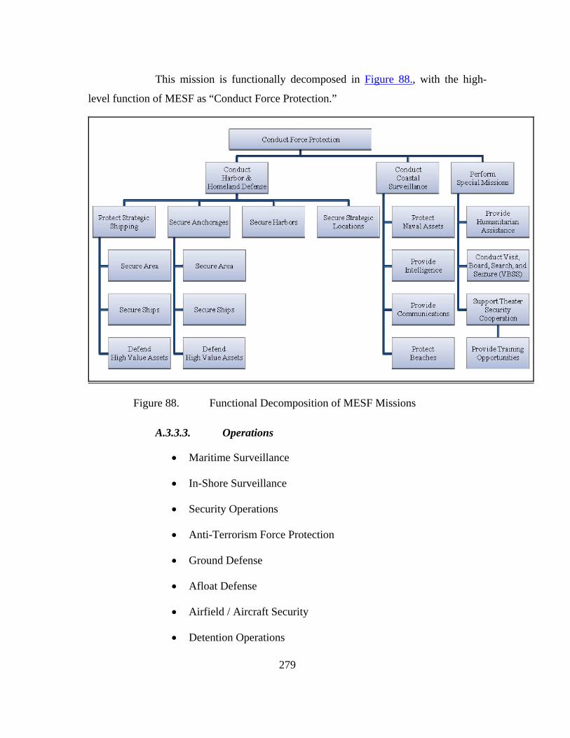
279
This mission is functionally decomposed in Figure 88., with the high-
level function of MESF as “Conduct Force Protection.”
Figure 88. Functional Decomposition of MESF Missions
A.3.3.3. Operations
• Maritime Surveillance
• In-Shore Surveillance
• Security Operations
• Anti-Terrorism Force Protection
• Ground Defense
• Afloat Defense
• Airfield / Aircraft Security
• Detention Operations

280
• Law Enforcement
A.3.3.4. Roles
• Conducts scalable force protection and security for designated
assets
• Provides layered defense in an integrated coastal and landward
security environment
• Provides the NCC/JFMCC with adaptive force packages
responsive to mission requirements
• Provides integrated maritime expeditionary security capabilities
including:
o Mobile and fixed defensive operations
o Visit, Board, Search and Seizure (VBSS) Level III
o Robust security in support of JFMCC operations across
the spectrum of maritime engagement
• Supports Partner Nation Theater Security Cooperation (TSC)
operations
• Provides training capability for partnering with other nations
• Supports Host Nation Security, Stabilization and Reconstruction
Operations (SSTRO)
• Provides Maritime Interception Operations (MIO) Exploitation
Teams
• Supports Maritime Expeditionary Intelligence Operations
A.3.3.5. Operational Limitations
• Small units that cannot sustain during high intensity missions
• Can only gain local control of river where actively patrolling
281
• Limited fire power (need fire support)
• Cannot conduct direct combat against a large organized armed
force
• Situational awareness (need ISR support)
A.3.3.6. Environment
• Near Coast Area
o Ground
o Littoral Area
A.3.3.7. Threats
• Small Surface Crafts
o Smugglers
o Traffickers
o Harassing State Actors
• Small Aircraft
o Single engine Propeller
o Unmanned drones
• Undersea and Submersibles
o Smuggling submarines
o Divers
o Mines
o Improvised Explosive Devices
• Electronic Warfare
o Friendly Communication Exploitation
282
o Frequency management
A.4. POTENTIAL NECC APPLICATIONS TO 2030 JOINT UMS
ARCHITECTURE
A.4.1. Riverine Force
Management of Assets
Manned / unmanned vehicle cooperation
Advance Scouts
Unmanned Patrols
Aerial or surface Fire Support
Obstacle detection and avoidance
Threat Assessment
A.4.2. Naval Construction (SEABEES)
Management of Assets
Unit Area Defense
Construction Assistance
A.4.3. Explosive Ordnance Disposal
Management of Assets
Identification of hazards
Unmanned removal of explosives
Personnel Recovery devices
Underwater Reconnaissance
Threat Assessment

283
A.4.4. Maritime Expeditionary Security Force
Management of Assets
Manned / unmanned vehicle cooperation
UV Swarm Capability and Countering
Unmanned Patrols
Aerial or surface Fire Support
Threat Assessment
A.4.5. Expeditionary Intelligence
Unmanned Surveillance
Cross-domain Threat Assessment
Timely information distributed through network
A.4.6. Expeditionary Logistics
Management of Assets
Identification of hazardous materials
Unmanned vehicle cargo handling
A.4.7. Maritime Civil Affairs
Management of Civil Operations
Unmanned Surveillance
Area Defensive Perimeter
A.4.8. Security Force Assistance
Network training for coalition partners

284
A.4.9. Combat Camera
Cross-domain Threat Information
Timely imaging from Unmanned Systems
Images quickly distributed through network
A.4.10. Expeditionary Combat Readiness
Management of Assets
Images quickly distributed through network
A.5. OPERATIONAL SCENARIOS
A.5.1. OPSIT 1: Oil Platform (OILPLAT) Protection
The situation is based on the current day usage of a Naval Expeditionary Combat
Command (NECC) Maritime Expeditionary Security Force (MESF) securing an
Oil Platform (OILPLAT) in the Arabian Gulf.
Assumption: Routine day
Initial set-up for the security forces are in place
Unmanned Systems (UMS) are on a rotating basis to ensure 24/7
coverage for the organic forces stationed on the OILPLAT.
Threat: Unknown incoming surface vessel on an intercept course to the
OILPLAT.
Resources: USVs
UAVs
Manned MESF RHIB
MESF Sentries on the OILPLAT
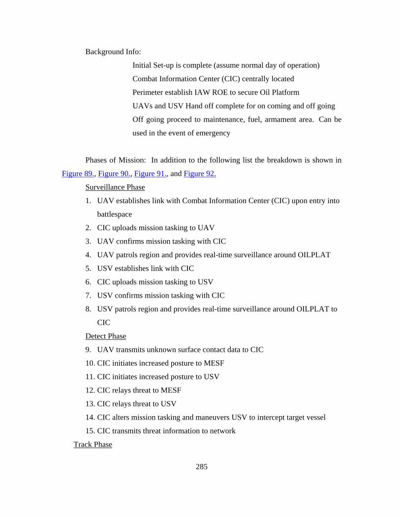
285
Background Info:
Initial Set-up is complete (assume normal day of operation)
Combat Information Center (CIC) centrally located
Perimeter establish IAW ROE to secure Oil Platform
UAVs and USV Hand off complete for on coming and off going
Off going proceed to maintenance, fuel, armament area. Can be
used in the event of emergency
Phases of Mission: In addition to the following list the breakdown is shown in
Figure 89., Figure 90., Figure 91., and Figure 92.
Surveillance Phase
1. UAV establishes link with Combat Information Center (CIC) upon entry into
battlespace
2. CIC uploads mission tasking to UAV
3. UAV confirms mission tasking with CIC
4. UAV patrols region and provides real-time surveillance around OILPLAT
5. USV establishes link with CIC
6. CIC uploads mission tasking to USV
7. USV confirms mission tasking with CIC
8. USV patrols region and provides real-time surveillance around OILPLAT to
CIC
Detect Phase
9. UAV transmits unknown surface contact data to CIC
10. CIC initiates increased posture to MESF
11. CIC initiates increased posture to USV
12. CIC relays threat to MESF
13. CIC relays threat to USV
14. CIC alters mission tasking and maneuvers USV to intercept target vessel
15. CIC transmits threat information to network
Track Phase

286
16. CIC alters USV tasking to monitor threat
17. UAV tracks targets and transmits updated video and data to CIC
Engage Phase
18. CIC transits warning via USV onboard communication gear to the target
craft.
19. CIC transmits updated threat information to network
20. CIC authorizes USV to engages hostiles with onboard weapons
21. CIC authorizes MESF to engage hostiles
22. MESF transmits Battle Damage Assessment (BDA) data to CIC
23. USV transmits BDA data to CIC
24. UAV transmits BDA data to CIC
25. CIC transmits downgraded protective posture to UAV
26. CIC transmits downgraded protective posture to MESF
27. CIC transmits downgraded protective posture to USV
28. CIC transfers UAV to surveillance mode
29. CIC transfers USV to surveillance mode
30. MESF restored to stand-by posture by CIC
31. CIC transmits downgraded posture to the network
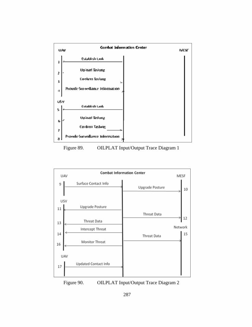
287
Figure 89. OILPLAT Input/Output Trace Diagram 1
Figure 90. OILPLAT Input/Output Trace Diagram 2
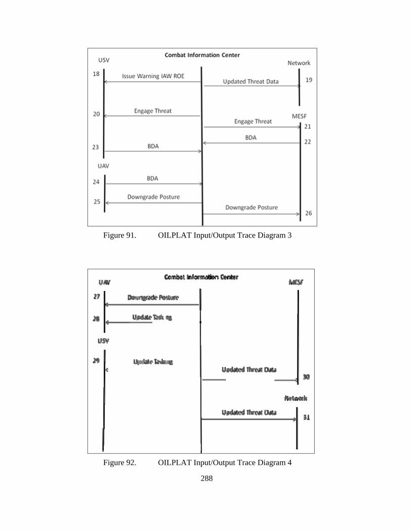
288
Figure 91. OILPLAT Input/Output Trace Diagram 3
Figure 92. OILPLAT Input/Output Trace Diagram 4

289
A.5.2. OPSIT 2: RIVERINE PATROL
The situation is based on the current day usage of a Naval Expeditionary Combat
Command (NECC) Riverine Force performing a routine patrol in support of
waterborne security.
Assumption: Routine day
Initial set-up for the security forces are in place
Unmanned Systems (UMS) are on a rotating basis to ensure 24/7
coverage for the organic forces.
Patrol initiates from a secure US controlled area
Threat: Ambush from insurgents using watercraft
Ambush from insurgents from positions overlooking the river
Resources: USVs
UAVs
Manned Riverine RHIB
Background Info:
Initial Set-up is complete (assume normal day of operation)
Combat Information Center centrally located
Perimeter establish IAW ROE to protect Riverine Patrol
Phases of Mission: In addition to the following list the breakdown is shown in
Figure 93., Figure 94., and Figure 95.
Launch Phase
1. Riverine RHIB requests surveillance of patrol area
2. Launch Riverine RHIBs
3. UAV establishes link with Combat Information Center (CIC) upon entry into
battlespace
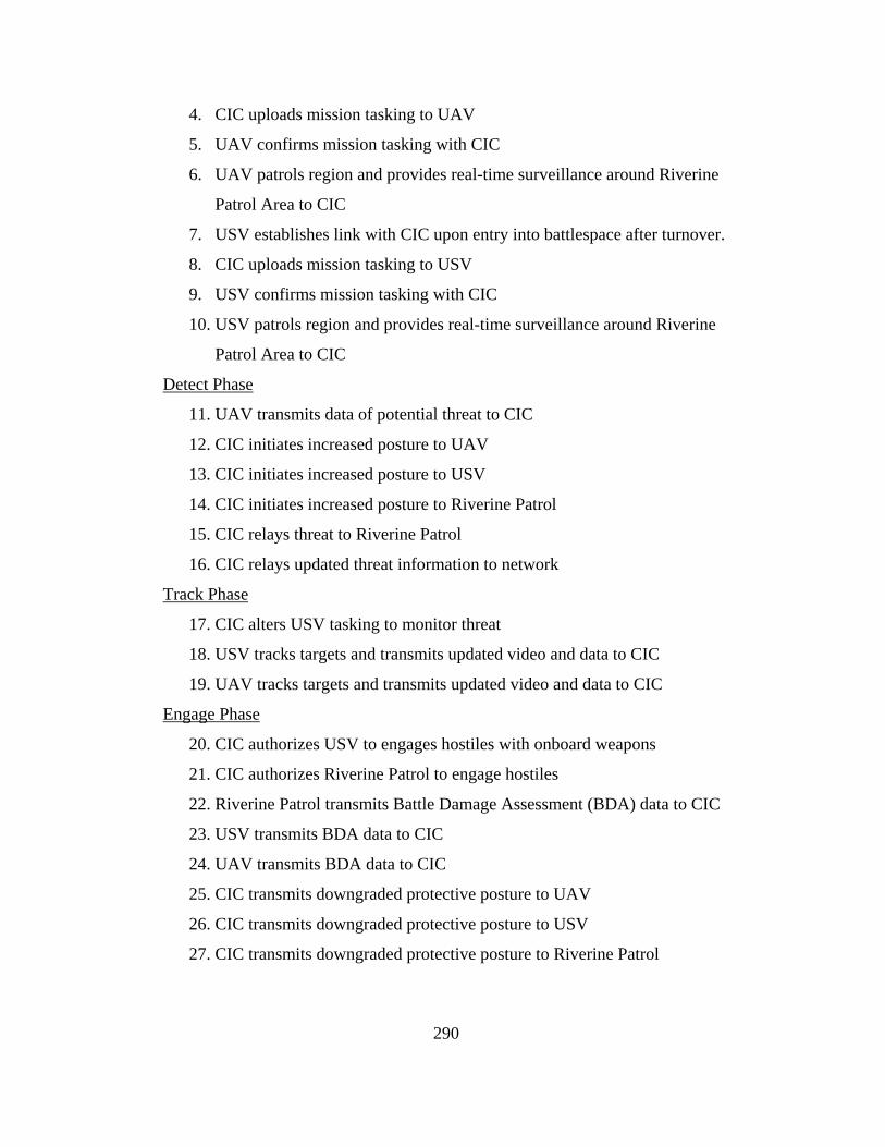
290
4. CIC uploads mission tasking to UAV
5. UAV confirms mission tasking with CIC
6. UAV patrols region and provides real-time surveillance around Riverine
Patrol Area to CIC
7. USV establishes link with CIC upon entry into battlespace after turnover.
8. CIC uploads mission tasking to USV
9. USV confirms mission tasking with CIC
10. USV patrols region and provides real-time surveillance around Riverine
Patrol Area to CIC
Detect Phase
11. UAV transmits data of potential threat to CIC
12. CIC initiates increased posture to UAV
13. CIC initiates increased posture to USV
14. CIC initiates increased posture to Riverine Patrol
15. CIC relays threat to Riverine Patrol
16. CIC relays updated threat information to network
Track Phase
17. CIC alters USV tasking to monitor threat
18. USV tracks targets and transmits updated video and data to CIC
19. UAV tracks targets and transmits updated video and data to CIC
Engage Phase
20. CIC authorizes USV to engages hostiles with onboard weapons
21. CIC authorizes Riverine Patrol to engage hostiles
22. Riverine Patrol transmits Battle Damage Assessment (BDA) data to CIC
23. USV transmits BDA data to CIC
24. UAV transmits BDA data to CIC
25. CIC transmits downgraded protective posture to UAV
26. CIC transmits downgraded protective posture to USV
27. CIC transmits downgraded protective posture to Riverine Patrol

291
28. CIC authorizes Riverine Patrol return to base for re-supply and re-
deployment
Figure 93. RIVERINE Input/Output Trace Diagram 1

292
Figure 94. RIVERINE Input/Output Trace Diagram 2
Figure 95. RIVERINE Input/Output Trace Diagram 3

293
THIS PAGE INTENTIONALLY LEFT BLANK
294
APPENDIX B UNMANNED SYSTEMS RESEARCH
Appendix B is a compilation of Unmanned Systems (UMS) that are either in use
in the field, in testing, in the research and development phase, or future concepts or
systems.
Appendix B was used to assist in the development of the model and simulations
in the project to assess the viability of the concept. While the project used only open
sources data on the Predator UAV, the model is functional enough that obtained data for
many UMS could be used to run the model and test it for usefulness. The Predator data
was used as the baseline and reasonable extrapolations for future systems of a “Predator-
like” UAV for future use.
Appendix B are broken up into the six sections. The first section is a history of
UMS, and the following five section are divided into the categories previously described
in the paper; UAV, USV, UUV, UGV, and UOSV.
B.1. HISTORICAL MILITARY USAGE OF UMS
UMS are not a new development and can be traced back almost a century. In
World War I, the Imperial German Navy used FL-boats (Fernlenkboote) which were
wired guided from shore and assisted by manned spotter aircraft to attack and destroy
coastal shipping.127
In the Winter War against Finland and in the early stages of World War II the
Soviet Red Army employed remotely controlled teletanks. While only capable of less
than a mile of distance for control, they were still able to take the “man” out of the
immediate battlefield. The Red Army also employed remote controlled cutters and
experimented with aircraft.128
127 Imperial Germany UMS, available from http://www.absoluteastronomy.com/, accessed January
20, 2010. 128Soviet Red Army UMS, available from http://www.absoluteastronomy.com/, accessed January 20,
2010.

295
Similar to the Germans and Soviets, the US also experimented with unmanned
vehicles in the early years of the 20th Century. Prior to WWI the US Navy developed a
sea plane that was capable of unmanned flight. In WWII the Navy also used plywood
UAV for attacking heavily defended targets.129
Project Aphrodite was an Army Air Corps that used older B-17 Flying Fortress
flown to altitude by a pilot, who would then eject. The the B-17 would be piloted
remotely from a second B-17 and crashed into the intended target to limit losses of
aircraft and crews over difficult targets. Another aspect of this was the use of drone B-
17’s during the atomic tests in the South Pacific. Another Army project involved the
development of a reconnaissance UAV from a drone. Initially fitted with cameras they
were later modified with television systems.130
By 1964, an Air Force drone reconnaissance program, known as Buffalo Hunter,
was under full development. A C-1 30D aircraft could carry up to four drones under its
wings, flying out of Vietnam they would launch them like missiles on a preprogrammed
flight over enemy held territory. From the mid-1960s until the end of the Vietnam War,
more than 3,000 missions were flown over North Vietnam and China. 131
Another Vietnam ear UAV program run by the Navy involved helicopters
equipped with television cameras and torpedoes, to attack supply barges in the Mekong
Delta. This program had limited success, mainly because of limited capability caused
by the technology immaturity of the flight gyroscopes of the times.132
Following Vietnam, it was noted that Remotely Piloted Vehicles (RPV) had the
potential for added value in the modern battlefield and force structure. A group called
the National Association of Remotely Piloted Vehicles (NARPY) was established. Over
several decades, research and development in UMS grew globally, and that group
evolved to include the international community. Now, this group is known as the
129 UAV Introduction, available from http://www.globalsecurity.org/, accessed January 20, 2010. 130 Ibid. 131 Ibid. 132 Ibid,
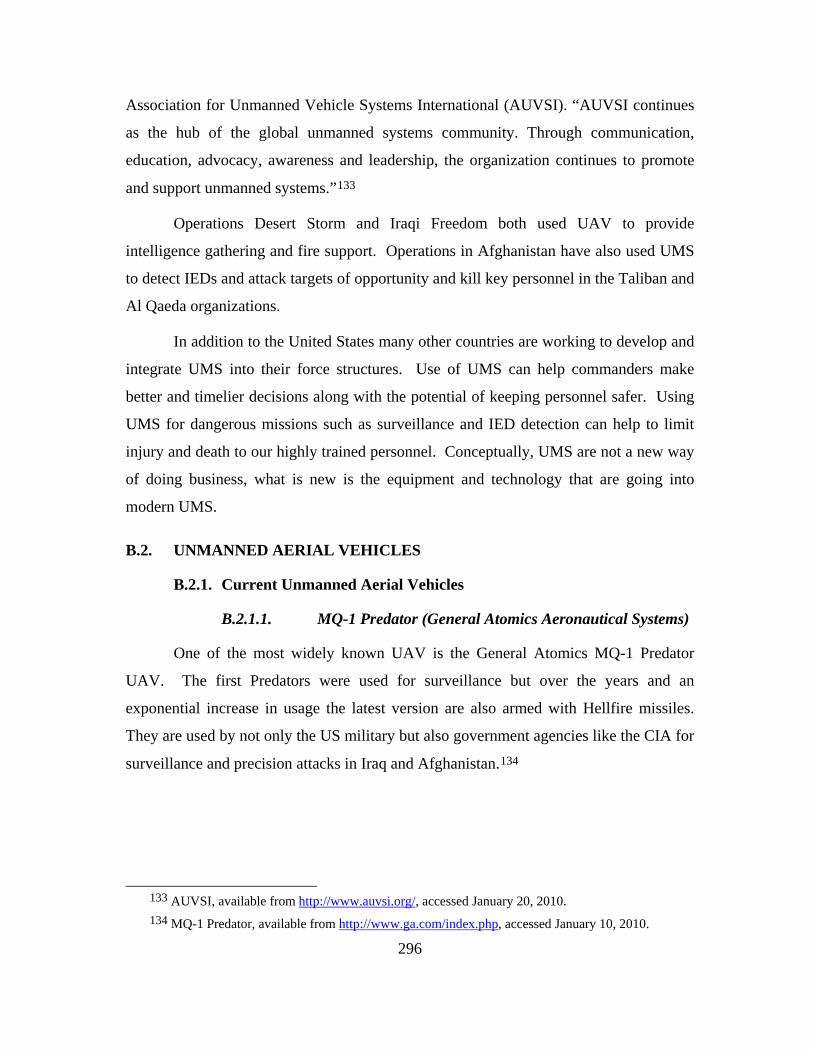
296
Association for Unmanned Vehicle Systems International (AUVSI). “AUVSI continues
as the hub of the global unmanned systems community. Through communication,
education, advocacy, awareness and leadership, the organization continues to promote
and support unmanned systems.”133
Operations Desert Storm and Iraqi Freedom both used UAV to provide
intelligence gathering and fire support. Operations in Afghanistan have also used UMS
to detect IEDs and attack targets of opportunity and kill key personnel in the Taliban and
Al Qaeda organizations.
In addition to the United States many other countries are working to develop and
integrate UMS into their force structures. Use of UMS can help commanders make
better and timelier decisions along with the potential of keeping personnel safer. Using
UMS for dangerous missions such as surveillance and IED detection can help to limit
injury and death to our highly trained personnel. Conceptually, UMS are not a new way
of doing business, what is new is the equipment and technology that are going into
modern UMS.
B.2. UNMANNED AERIAL VEHICLES
B.2.1. Current Unmanned Aerial Vehicles
B.2.1.1. MQ-1 Predator (General Atomics Aeronautical Systems)
One of the most widely known UAV is the General Atomics MQ-1 Predator
UAV. The first Predators were used for surveillance but over the years and an
exponential increase in usage the latest version are also armed with Hellfire missiles.
They are used by not only the US military but also government agencies like the CIA for
surveillance and precision attacks in Iraq and Afghanistan.134
133 AUVSI, available from http://www.auvsi.org/, accessed January 20, 2010. 134 MQ-1 Predator, available from http://www.ga.com/index.php, accessed January 10, 2010.

297
Figure 96. General Atomics MQ-1 Predator UAV.135
Habitat: The skies of Afghanistan, Pakistan and Iraq.
Behavior: Predator, as shown in Figure 96., is one of only two major U.S.
unmanned systems that carry weapons (in this case, two Hellfire air-to-ground missiles),
the Predator bears the brunt of the hunter-killer role with its successor, the beefier MQ-9
Reaper. It has a range of 400 nautical miles, and an endurance of 40 hours.136
Notable Features: The Predator was first drone system to see heavy use both
as a reconnaissance platform and in an attack role, first seeing action in Bosnia in the
mid 1990s. The name "Predator" is now almost synonymous with hunter-killer UAVs.
Configured with a satellite data link system, Predator is equipped with an EO/IR
stabilized gimbal containing two color video cameras and a forward-looking infrared
(FLIR) camera as well as a synthetic aperture radar (SAR). The Predator has been
configured with air-to-air or air-to-ground weapons as well as a laser designator. Since
1995, Predator has logged over 405,000 flight hours, of which over more than half have
been during combat area deployments to the Balkans, Southwest Asia, and the Middle
East where Predator operates in support of U.S. and NATO forces. Based upon the
135 MQ-1 Predator, available from http://www.ga.com/index.php, accessed January 10, 2010. 136 Popular Science Magazine The Complete UAV Field Guide
http://www.popsci.com/technology/gallery/2010-02/gallery-future-drones

298
success of the program, the U.S. Department of Defense transitioned the Predator
program to full rate production in August 1997, marking it as the first Advanced
Concept Technology Demonstration (ACTD) program to be designated an Acquisition
Category II Program.
Predators are currently in production for the U.S. and Italian Air Force. Land-
based Predators have demonstrated the ability to support maritime forces including
carrier battle groups, amphibious ready groups, and submarines. Predator is the only
reconnaissance system available in the U.S. inventory that can provide near real-time
video imagery day or night in all weather conditions via satellite worldwide - without
exposing pilots to combat fire. As the first successful unmanned aircraft surveillance
program, Predator provides tactical and strategic intelligence to operational commanders
worldwide.137
Features:
• Solid-state digital avionics
• Remotely piloted or fully autonomous
• SAR and EO/IR providing day/night and all-weather operations in one-
mission aircraft
• GPS and INS
• UHF/VHF voice
• Extensive combat experience
Capabilities:
• Expanded EO/IR payload
• SAR all-weather capability
• Satellite control
• GPS and INS
• Endurance of 40 hours and a range 400 nmi
• Deployed with the U.S. and Italian Air Force
137 General Atomics Aeronautical “Predator” http://www.ga-asi.com/products/aircraft/predator.php

299
• Operations to 25,000 ft (7620m)
• 450 lb (204 kg) payload
• Wingspan 48.7 ft (14.84m), length 27 ft (8.23m)
B.2.1.2. MQ-9 Reaper (General Atomics Aeronautical Systems)
Figure 97. General Atomics Reaper MQ-9 UAV138
Habitat: Hunting and killing insurgents in Iraq, Afghanistan, and
Pakistan. Patrolling the U.S. Mexican Border out of Fort Huachuca, Arizona.
Behavior: Reaper, as shown in Figure 97., has a wingspan of 66 feet,
it’s twice the size of its precursor MQ-1 Predator, and can loiter at 5,000 feet for up to
24 hours. Loaded with 3,000 pounds of munitions, including the GBU-12 laser-guided
bomb and Hellfire tank-penetrating missiles, military commanders say it has become
one of their most effective weapons in the current wars.139
138 General Atomics Reaper MQ-9 UAV,
http://www.afrc.af.mil/photos/mediagallery.asp?galleryID=332, accessed May 15, 2010. 139 Popular Science Magazine The Complete UAV Field Guide
http://www.popsci.com/technology/gallery/2010-02/gallery-future-drones, accessed May 15, 2010.

300
Notable Feature: After being launched by operators using radio-
control equipment, it’s flown via satellite link from pilots on safe soil in the U.S.
B.2.1.3. ScanEagle (Insitu/Boeing)
Another system that is gaining ground in the US Navy is ScanEagle. Compact
and lightweight ScanEagle can be operated from even the smallest naval ships; including
the Mark V naval special warfare craft or flight deck of any surface ship with its catapult
launching system and a patented “Skyhook” retrieval system. ScanEagle is strictly a
surveillance platform with either a stabilized electro-optical or infrared cameras for day
and night surveillance. The latest version being tested is capable of 22hours of flight
time.140
Figure 98. Insitu/Boeing ScanEagle.141
140 ScanEagle, available from http://www.boeing.com/, accessed January 10, 2010. 141 Ibid.

301
Figure 99. Insitu/Boeing ScanEagle.142
Habitat: With Marine Corps troops in Iraq or aboard U.S. Navy
ships anywhere in the world.
Behavior: ScanEagle, as shown in Figure 98. and Figure 99., weighs
40 pounds and is four-feet long with a 10.2-foot wingspan. Powered by a gasoline
engine for 15 hours. Its catapult launch makes it ideal for tight spaces, like the deck of
the ship that rescued Capt. Richard Phillips from Somali pirates last in April 2010.143
Notable Feature: To land, the ScanEagle’s navigation points it
toward a sky-hook that snares it out of the sky. Developed in partnership with The
Boeing Company, ScanEagle is highly stealth at very low altitudes enabled by a low
acoustic, visual, and infrared range signature, an advanced muffler, and a mature
modular design that enables carriage of electro-optic or infrared imaging payloads.144
142 Ibid. 143 Popular Science Magazine The Complete UAV Field Guide
http://www.popsci.com/technology/gallery/2010-02/gallery-future-drones, accessed May 15, 2010. 144 INSITU “Scan Eagle” http://www.insitu.com/scaneagle, accessed January 20, 2010.

302
B.2.1.4. RQ-11B Raven
Figure 100. RQ-11B Raven145
Habitat: The Raven, as shown in Figure 100., is the most prevalent UAV
on the planet, with more than 7,000 units in service. The RQ-11B is currently being
used in Iraq and Afghanistan by army brigades.
Behavior: The RQ-11B not only provide situational awareness it also
provide target information for Air Force Special Operations Command Battlefield
Airmen and Air Force security forces. The Raven falls into the class of Air Force small
UAS known as man-portable UAS.146
145 Air Force Official Site “RQ-11B Raven”
http://www.af.mil/information/factsheets/factsheet.asp?id=10446, accessed May 15, 2010. 146 Ibid.

303
Spec: The Raven is typically fitted with an electronically stabilized color video
camera or an infrared video camera for night missions, which pan, tilt and zoom
digitally to provide ground troops with “situational awareness.” The fleet is expecting a
digital upgrade that turns the Raven into a communications relay, effectively extending
its six-mile range.
Features: The Raven back-packable system which features two air vehicles
or AVs, a ground control unit, remote video terminal, transit cases and support
equipment. Two specially trained Airmen operate the Raven AV. The AV can be
controlled manually or can autonomously navigate a preplanned route.147
Notable Feature: Light and durable design allows for easy replacement of
wings upon a crash. The Raven also includes a color electro-optical camera and an
infrared camera for night operations. The air vehicle is hand-launched.
General Characteristics2
Primary Function: Reconnaissance and surveillance with low altitude
operation
Contractor: Aerovironment, Inc.
Power Plant: Electric Motor, rechargeable lithium ion batteries
Wingspan: 4.5 feet (1.37 meters)
Weight: 4.2 lbs (1.9 kilograms)
Weight (ground control unit): 17 lbs (7.7 kilograms)
Speed: 30-60 mph (26-52 knots)
Range: 8-12 km (4.9-7.45 miles)
Endurance: 60-90 minutes
Altitude (operations): 100-500 feet air ground level ( to 152 meters)
147 Ibid.
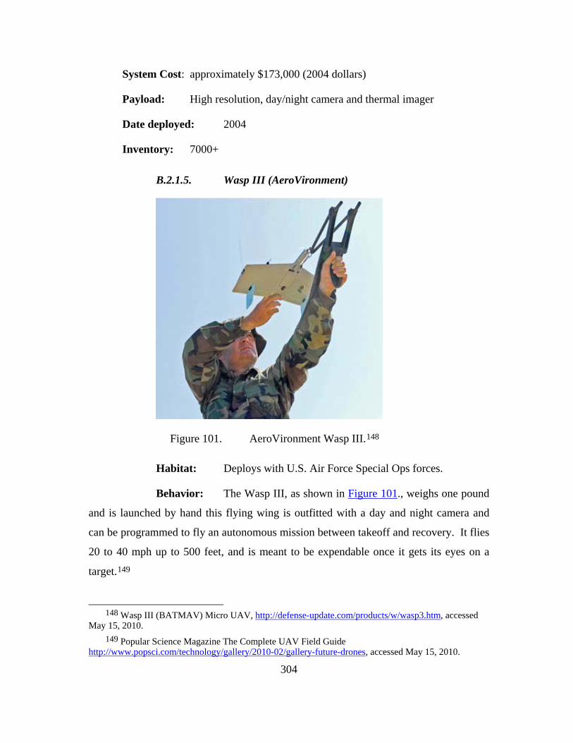
304
System Cost: approximately $173,000 (2004 dollars)
Payload: High resolution, day/night camera and thermal imager
Date deployed: 2004
Inventory: 7000+
B.2.1.5. Wasp III (AeroVironment)
Figure 101. AeroVironment Wasp III.148
Habitat: Deploys with U.S. Air Force Special Ops forces.
Behavior: The Wasp III, as shown in Figure 101., weighs one pound
and is launched by hand this flying wing is outfitted with a day and night camera and
can be programmed to fly an autonomous mission between takeoff and recovery. It flies
20 to 40 mph up to 500 feet, and is meant to be expendable once it gets its eyes on a
target.149
148 Wasp III (BATMAV) Micro UAV, http://defense-update.com/products/w/wasp3.htm, accessed
May 15, 2010. 149 Popular Science Magazine The Complete UAV Field Guide
http://www.popsci.com/technology/gallery/2010-02/gallery-future-drones, accessed May 15, 2010.

305
Notable Feature: Electrically powered, two-bladed propeller makes
it very quiet. Its inventory is classified. This UAV was developed under a DARPA
Micro-UAV program. Wasp III is equipped with forward and side looking color video
cameras, as well as a modular forward or side looking electo-optical infrared payload.
To maintain continuous coverage of a specific target, the Wasp automatically circles
around it, maintaining the designated target in the side camera's field of view. The
system is packed in a small suitcase, rapidly assembled within few minutes and is
launched by hand toss. 150
B.2.1.6. Desert Hawk (Lockheed Martin)
Figure 102. Lockheed Martin Desert Hawk.151
Habitat: Used by British and American troops in Afghanistan.
150 Defense Update “Wasp III Micro UAV” http://defense-update.com/products/w/wasp3.htm,
accessed May 15, 2010. 151 Lockheed Martin Desert Hawk., http://www.armybase.us/2009/05/lockheed-martin-successfully-
tests-signals-intelligence-capability-and-improved-wing-design-on-desert-hawk-iii-unmanned-aircraft-system/, accessed May 15, 2010.

306
Behavior: After manned launch the Desert Hawk, as shown in Figure
102., follows pre-programmed coordinates to give troops an “over-the-hill” view, day or
night, up to six miles away. At two pounds (with a collapsible 4.5-foot wingspan), it’s
easy to transport.
Notable Feature: Built of injection-molded expanded polypropylene
and fitted with Kevlar skids, the Desert Hawk is as durable as a Nerf.152 The Desert
Hawk III is designed for portability, quick mission planning, hand launched and skid
recovery, multi-mission versatility, enhanced day/night target detection, recognition,
identification, greater operational range, endurance and covert operations. Desert Hawk
III provides persistent surveillance by the use of a gyro-stabilized 360-degree sensor
turret, color and low light electro-optical plug-and-play payloads, and roll-stabilized
infrared sensor payloads. It consists of a rugged air vehicle and a lightweight, portable
ground station, which provides operator training, autonomous pre-flight planning, in-
flight control of plug-and-play optical and infrared sensors, terrain avoidance measures,
and the ability to provide real time dynamic in-flight mission and flight profile re-
tasking.153
152 Popular Science Magazine The Complete UAV Field Guide
http://www.popsci.com/technology/gallery/2010-02/gallery-future-drones, accessed May 15, 2010. 153 Lockheed Martin “Desert Hawk III”
http://www.lockheedmartin.com/products/DesertHawk/index.html, accessed May 15, 2010.

307
B.2.1.7. MD4-200 (Microdrone)
Figure 103. Microdrone MD4-200154
Habitat: Used by the police in Liverpool, UK as an Anti-social
Behavior Task Force.
Behavior: The Microdrone, as shown in Figure 103., is a four-rotor
design of the battery-powered, carbon-fiber pod, which weighs just 2.2 pounds, allows it
to take off and land vertically. Brushless, direct-drive electric motors keep the noise
level below 64 decibels, according to the company.
Notable Feature: If it loses signal or senses a low battery, it will land
itself autonomously rather than crash.155 Drone has been designed completely in carbon
fiber reinforced plastics, which makes it light and shields against electromagnetic
interferences. Depending on payload, temperature and wind the vehicle achieves up to
20 minutes of flight time.156
154 Microdrone MD4-200, http://www.gedop.org/blog/galeri/insansiz-casus-ucaklar, accessed May
15, 2010. 155 Popular Science Magazine The Complete UAV Field Guide
http://www.popsci.com/technology/gallery/2010-02/gallery-future-drones, accessed May 15, 2010. 156 Micro Drones “MD4-200” http://www.microdrones.com/en_md4-200_introduction.php, accessed
May 15, 2010.

308
B.2.1.8. T-Hawk/gMAV (Honeywell)
Figure 104. Honeywell T-Hawk/gMAV.157
Habitat: Utilized by the U.S. Army infantry in Iraq.
Behavior: T-Hawk, as shown in Figure 104., provides EOD the
ability to view an EOD incident from a perspective other than that of a ground robotic
system.158
Notable Feature: VTOL T-Hawk weighs 16 pounds and can fly up
to10,000 feet for up to 45 minutes.
157 Honeywell T-Hawk/gMAV. http://www.gedop.org/blog/galeri/insansiz-casus-ucaklar. accessed
May 15, 2010. 158 BNET “Navy Buys 90 Honeywell Micro Air Vehicles for EOD Teams”
http://findarticles.com/p/articles/mi_6712/is_27_240/ai_n31060866/, accessed May 15, 2010.

309
B.2.1.9. Aerosonde (AAI Corporation)
Figure 105. AAI Corporation Aerosonde159
Habitat: Stormy seas, or any other inhospitable or inaccessible spot
scientific researchers want to study up close.
Behavior: Aerosonde, as shown in Figure 105., was the first UAV to
cross the Atlantic Ocean, back in 1998, the 9.8-foot, 28-pound research craft can fly up
to 30 hours on a single tank of gas. In 2007 it delivered unprecedented weather readings
from Hurricane Noel, loitering as low as 300 feet above the surface, and streaming data
for more than seven hours before it was ditched in the ocean. 160
Notable Feature: The inverted V tail combines functions of what
would be the horizontal and vertical parts of the tail wing, saving weight. It has one
horsepower.
159 AAI Corporation Aerosonde, http://www.gedop.org/blog/galeri/insansiz-casus-ucaklar, accessed May 15, 2010.
160 Popular Science Magazine The Complete UAV Field Guide http://www.popsci.com/technology/gallery/2010-02/gallery-future-drones, accessed May 15, 2010.
310
With a full electro-optic/infrared payload, the Aerosonde aircraft can
achieve more than 10 hours endurance. It can land via belly or net capture using AAI’s
proprietary launch and recovery trailer, or LRT, system with Soft Hands™ recovery
technology.
With these capabilities, the Aerosonde aircraft has accumulated several
significant flight milestones including161:
• The Aerosonde Mark 4.7 was showcased at the 2010 Bahrain Air
Show, where the flight team conducted the system’s first flights in
the Middle East region. These included a flight during a driving
sand storm, which displayed the aircraft’s rugged, all-weather
capability.
• In 2009, the Aerosonde Mark 4.7 system was introduced to
provide expeditionary intelligence, surveillance and
reconnaissance. Including the novel Soft Hands net recovery
technology, the system rounded out the year with a successful
shipboard launch and recovery demonstration off the M-80
Stiletto ship.
• In 2007, an Aerosonde was the first unmanned aircraft to
penetrate the eye of a hurricane. Under a program administered
by NASA and the U.S. National Oceanic and Atmospheric
Administration, the Aerosonde aircraft flew a mission of more
than 17 hours, a record 7.5 of which were spent navigating
Hurricane Noel’s eye and boundary layer.
• During 2006, the aircraft set a world flight endurance record in its
class by remaining in flight without refueling for more than 38
hours.
161 Aerosonde “Products and Services” http://www.aerosonde.com/products/products.html, accessed
May 15, 2010.
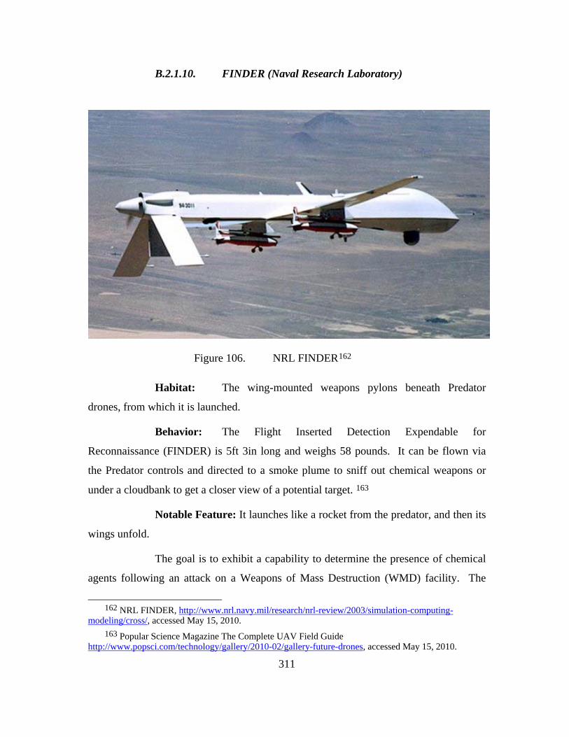
311
B.2.1.10. FINDER (Naval Research Laboratory)
Figure 106. NRL FINDER162
Habitat: The wing-mounted weapons pylons beneath Predator
drones, from which it is launched.
Behavior: The Flight Inserted Detection Expendable for
Reconnaissance (FINDER) is 5ft 3in long and weighs 58 pounds. It can be flown via
the Predator controls and directed to a smoke plume to sniff out chemical weapons or
under a cloudbank to get a closer view of a potential target. 163
Notable Feature: It launches like a rocket from the predator, and then its
wings unfold.
The goal is to exhibit a capability to determine the presence of chemical
agents following an attack on a Weapons of Mass Destruction (WMD) facility. The
162 NRL FINDER, http://www.nrl.navy.mil/research/nrl-review/2003/simulation-computing-
modeling/cross/, accessed May 15, 2010. 163 Popular Science Magazine The Complete UAV Field Guide
http://www.popsci.com/technology/gallery/2010-02/gallery-future-drones, accessed May 15, 2010.

312
FINDER will autonomously fly to a designated recovery site, at which it will
autonomously land and be recovered by friendly forces. The FINDER has a propulsion
system that used Predator aviation fuel and is able to sustain flight for 8 to 10 hours at
70 km/h airspeed which translates into an operational range of more than 350 nm.
Summary: FINDER supports the European Command requirements for a
chemical battle damage assessment tool. The vehicle and current payload provides real
time or near real time: local area meteorological data, integration with the existing
Predator infrastructure, Predator stand-off capability, critical sample collection, return of
sample to a safe area, and extended range egress.
As technology evolves, FINDER possesses the flexibility to accept a
wide variety of modular payloads and deployment options. Figure 106. shows a
demonstrated deployment alternative that was a fallout of the normal vehicle
development. Future growth capabilities are already being discussed as follow-on
options164:
• Toxic chemical/precursors sensing
o IMS detectors reprogrammable to add new signatures;
• Biological detection capability
o Preliminary study of mature technologies
o Flexibility for future payload integration options;
• NAVY at-sea base option
o Rail launch future capability is feasible;
• Radiological hazard sensing
o Flexibility for future payload integration options.
164 Navy Research Laboratory “ Finder UAV: A Counterpoliferation Asset”
http://www.nrl.navy.mil/research/nrl-review/2003/simulation-computing-modeling/cross/, accessed May 15, 2010.
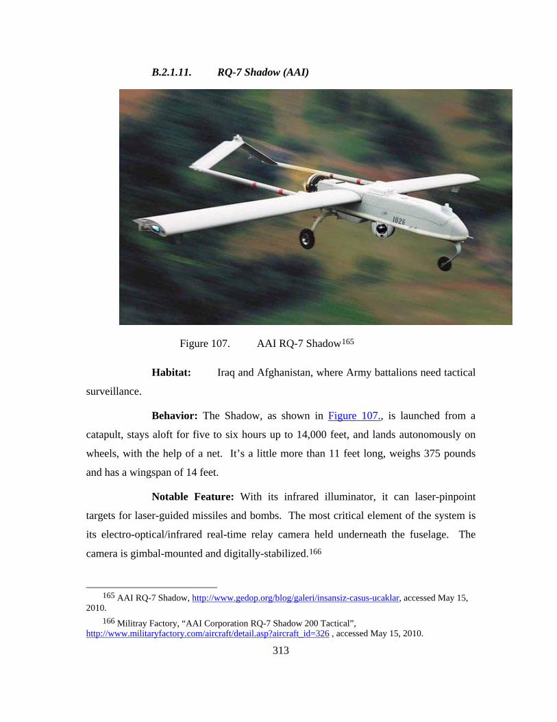
313
B.2.1.11. RQ-7 Shadow (AAI)
Figure 107. AAI RQ-7 Shadow165
Habitat: Iraq and Afghanistan, where Army battalions need tactical
surveillance.
Behavior: The Shadow, as shown in Figure 107., is launched from a
catapult, stays aloft for five to six hours up to 14,000 feet, and lands autonomously on
wheels, with the help of a net. It’s a little more than 11 feet long, weighs 375 pounds
and has a wingspan of 14 feet.
Notable Feature: With its infrared illuminator, it can laser-pinpoint
targets for laser-guided missiles and bombs. The most critical element of the system is
its electro-optical/infrared real-time relay camera held underneath the fuselage. The
camera is gimbal-mounted and digitally-stabilized.166
165 AAI RQ-7 Shadow, http://www.gedop.org/blog/galeri/insansiz-casus-ucaklar, accessed May 15,
2010. 166 Militray Factory, “AAI Corporation RQ-7 Shadow 200 Tactical”,
http://www.militaryfactory.com/aircraft/detail.asp?aircraft_id=326 , accessed May 15, 2010.

314
B.2.1.12. Heron (Israeli Aerospace Industries)
Figure 108. Israeli Aerospace Industries Heron167
Habitat: Watching over Israel, patrolling India’s borders with
Pakistan and China, looking for drug traffickers in El Salvador, and dozens of other
missions around the globe, where the unarmed surveillance craft is used by countries
importing it from Israel.
Behavior: With a 54-foot wingspan and max altitude ceiling of
30,000 feet, the Heron, as shown in Figure 108., uses an advanced collection of sensors
to stream data to its handlers. It can stay aloft for 52 hours.
Notable Feature: The Herron can take off and land autonomously,
even in poor weather conditions168:
The HERON I main features and capabilities are:
• Multiple operational configurations
• Adverse weather capability
• Safe, reliable and easy operation
167 Israeli Aerospace Industries Heron, http://www.gedop.org/blog/galeri/insansiz-casus-ucaklar,
accessed May 15, 2010. 168 Israeli Aerospace Industries “Heron” http://www.iai.co.il/18900-16382-
en/BusinessAreas_UnmannedAirSystems_HeronFamily.aspx?btl=1, accessed May 15, 2010.

315
• Simultaneously 4 sensors use capability
• Satellite communication for extended range (SATCOM)
• Two proven simultaneous Automatic Takeoff and Landing
(ATOL) systems for maximal safety
• Fully redundant, state-of-the-art avionics
• Retractable landing gear
B.2.1.13. Hermes 450/Watchkeeper (Elbit Systems)
Figure 109. Elbit Systems Hermes 450/Watchkeeper169
Habitat: Providing target coordinates over Israeli battlefields, and
reconnaissance for British troops in Iraq and Afghanistan.
Behavior: It can loiter for about 20 hours on its 34-foot wing, up to an
altitude of 18,000 feet, providing real-time surveillance to battlefield commanders.
Notable Features: The odd, torpedo-on-a-popsicle-stick design give
the craft a high payload to weight ratio: one third of its 992 pounds. It has two gimbals,
fore and aft, for surveillance gear. The UAV is equipped with sophisticated
169 Elbit Systems Hermes 450/Watchkeeper, http://www.gedop.org/blog/galeri/insansiz-casus-
ucaklar, accessed May 15, 2010.

316
communication systems transmitting imagery in real time to ground stations. Selected
as the base line for the UK WATCHKEEPER program, Hermes® 450, as shown in
Figure 109., is recognized as the leading long endurance tactical UAV in its class,
having flown in U.S. operations and history-making flights in UK civil airspace. To
date, the Hermes® 450 has accumulated more than 65,000 flight hours.170
B.2.1.14. MQ-5 Hunter (Northrup Grumman)
Figure 110. Northrup Grumman MQ-5 Hunter171
Habitat: Flown by the Army in Iraq and Afghanistan.
Behavior: The Hunter, as shown in Figure 110., has been in service
since just before the Balkans war, and was recently retrofitted in the MQ variant to run
on heavy fuel and carry Viper Strike munitions. It has a 34-foot wingspan and can fly
18 hours, up to 18,000 feet.
Notable Feature: It can be flown with the same ground control
station as the Shadow and the Army’s version of the Predator.172
170 Elbit Systems “Hermes 450” http://www.elbitsystems.com/lobmainpage.asp?id=161 accessed
May 15, 2010. 171 Northrup Grumman MQ-5 Hunter, http://www.gedop.org/blog/galeri/insansiz-casus-
ucaklar, accessed May 15, 2010.

317
B.2.1.15. RQ-4 Global Hawk (Northrop Grumman)
Figure 111. Northrup Grumman RQ-4 Global Hawk173
Habitat: High above Iraq, Afghanistan and Pakistan—or anywhere
else the U.S. Central Command wants to keep under watch.
Behavior: Soaring at 65,000 feet with an endurance of 36 hours, the
Global Hawk, as shown in Figure 111., can keep watch over 40,000 nautical square
miles per mission. Carrying a full suite of electro-optical, infrared and synthetic
aperture radar sensors, it can operate day and night in all weather conditions. The larger
variation has a 130-foot wingspan.
Notable Feature: The fact that it can take off and land autonomously
greatly reduces the potential for crashes, which have handicapped the Predator and
Reaper.
The Northrop Grumman RQ-4 Block 10 Global Hawk is currently
supporting the U.S. Air Force in the global war on terrorism. The Global Hawks are
172 Popular Science Magazine The Complete UAV Field Guide
http://www.popsci.com/technology/gallery/2010-02/gallery-future-drones accessd May 15, 2010. 173 Northrup Grumman RQ-4 Global Hawk, http://www.gedop.org/blog/galeri/insansiz-casus-
ucaklar, accessed May 15, 2010.

318
operated overseas by USAF pilots from a mission control element stationed at Beale Air
Force Base in Northern California. A launch and recovery element and a combined
USAF and Northrop Grumman team are forward deployed with the air systems. The
Global Hawk is equipped with electro-optical, infrared and synthetic aperture radar
sensors to provide high-quality real-time imagery.174
B.2.2. Future Unmanned Aerial Vehicles
B.2.2.1. Phantom Ray (Boeing Company)
Figure 112. Boeing Phantom Ray175
Habitat: Edwards Air Force Base, Lancaster, California
Behavior: Dervied from the Boeing Phantom Works’ defunct X-45C.
The prototype Phantom Ray, as shown in Figure 112., jet-powered flying wing has
morphed into a test bed for advanced UAV technologies, including electronic warfare
tools like radar jamming, autonomous aerial refueling, air-missile defense and
174 Northrup Grumman “Global Hawk”
http://www.as.northropgrumman.com/products/ghrq4a/index.html accessed May 15, 2010. 175 Boeing Phantom Ray, http://www.gedop.org/blog/galeri/insansiz-casus-ucaklar, accessed May
15, 2010.
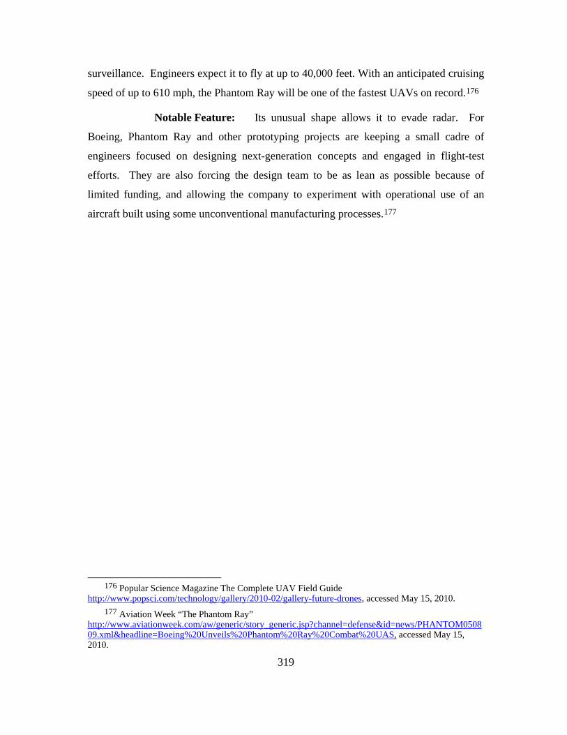
319
surveillance. Engineers expect it to fly at up to 40,000 feet. With an anticipated cruising
speed of up to 610 mph, the Phantom Ray will be one of the fastest UAVs on record.176
Notable Feature: Its unusual shape allows it to evade radar. For
Boeing, Phantom Ray and other prototyping projects are keeping a small cadre of
engineers focused on designing next-generation concepts and engaged in flight-test
efforts. They are also forcing the design team to be as lean as possible because of
limited funding, and allowing the company to experiment with operational use of an
aircraft built using some unconventional manufacturing processes.177
176 Popular Science Magazine The Complete UAV Field Guide
http://www.popsci.com/technology/gallery/2010-02/gallery-future-drones, accessed May 15, 2010. 177 Aviation Week “The Phantom Ray”
http://www.aviationweek.com/aw/generic/story_generic.jsp?channel=defense&id=news/PHANTOM050809.xml&headline=Boeing%20Unveils%20Phantom%20Ray%20Combat%20UAS, accessed May 15, 2010.
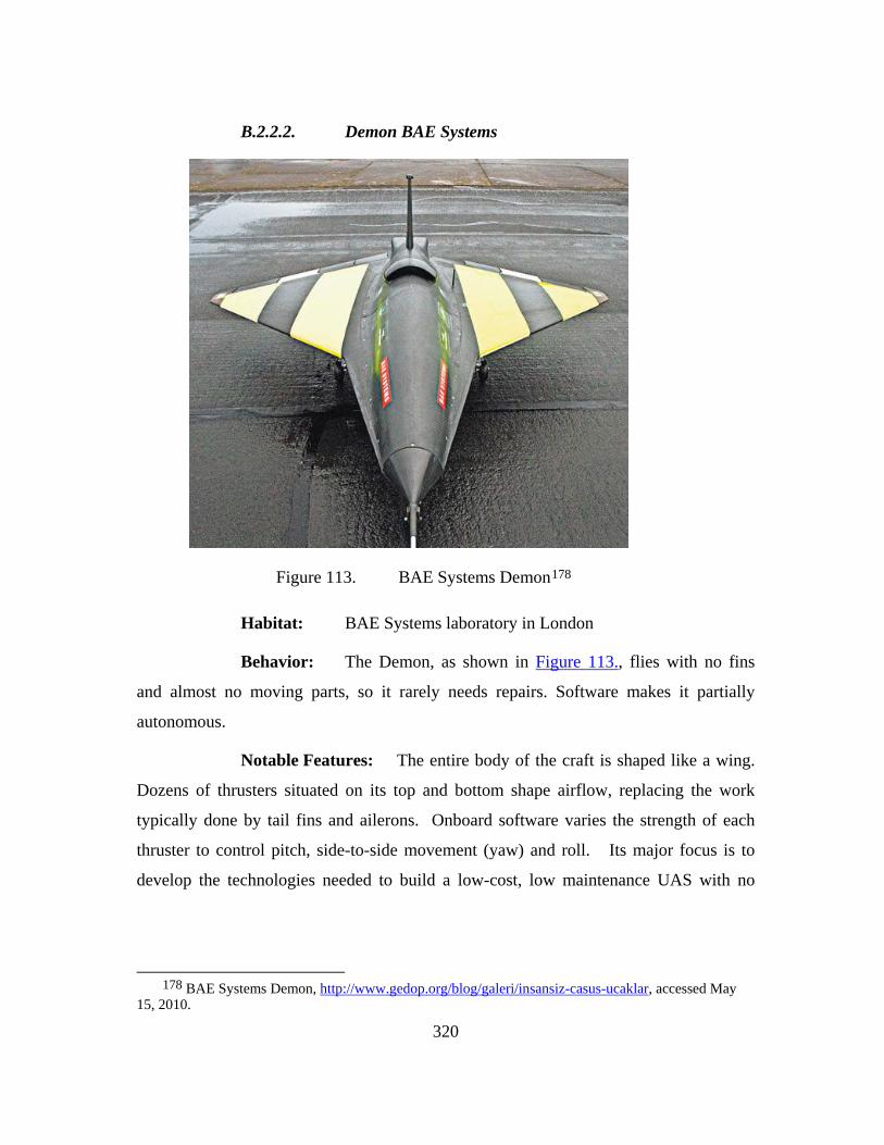
320
B.2.2.2. Demon BAE Systems
Figure 113. BAE Systems Demon178
Habitat: BAE Systems laboratory in London
Behavior: The Demon, as shown in Figure 113., flies with no fins
and almost no moving parts, so it rarely needs repairs. Software makes it partially
autonomous.
Notable Features: The entire body of the craft is shaped like a wing.
Dozens of thrusters situated on its top and bottom shape airflow, replacing the work
typically done by tail fins and ailerons. Onboard software varies the strength of each
thruster to control pitch, side-to-side movement (yaw) and roll. Its major focus is to
develop the technologies needed to build a low-cost, low maintenance UAS with no
178 BAE Systems Demon, http://www.gedop.org/blog/galeri/insansiz-casus-ucaklar, accessed May
15, 2010.

321
conventional control surfaces, such as wing flaps and without losing any performance
compared to conventional aircraft.179
B.2.2.3. Vulture Jim (Lockheed Martin)
Figure 114. Lockheed Martin Vulture Jim180
Habitat: A belt of relatively calm air around 55,000 feet
Behavior: The Vulture Jim, as shown in Figure 114., can stay aloft
for five years, turning lazy circles above any patch of ground that needs continuous
monitoring. A suite of day-and-night cameras can scan a 600-mile swath, sending data
back to handlers on the ground. The craft will have to beat out species from a Boeing-
led consortium and Virginia-based Aurora Flight Sciences for a second round of
funding.
179 BAE Systems “Demon” http://www.artisan3d.co.uk/Capabilities/Technologyinnovation/NewTechnologies/Demon/index.htm, accessed May 15, 2010.
180 Lockheed Martin Vulture Jim, http://www.gedop.org/blog/galeri/insansiz-casus-ucaklar, accessed May 15, 2010.

322
Notable Feature: The craft’s semi-flexible structure bends instead of
breaking when winds cause the long span to oscillate violently.181
B.2.2.4. RQ-170 Sentinel (Lockheed Martin)
Figure 115. Lockheed Martin RQ-170 Sentinal182
Habitat: Migrating from its suspected home base at Kandahar
Airfield, Afghanistan, this top-secret military spy drone makes classified sorties into
enemy terrain.
Behavior: An offspring of Lockheed Martin’s Skunk Works
program, the RQ-170 Sentinel, as shown in Figure 115., flies via satellite link from a
base in Tonopah, Nevada, but little else is know about it.
Notable Feature: Sensor pods built into the edge of its wings
probably give it surveillance capabilities, and the absence of a wing-mounted weapons
payload likely keeps it light and off the radar.183
181 Wired Magazine “War Drones of Now and Tomorrow”
http://www.wired.com/beyond_the_beyond/2010/03/war-drones-of-now-and-tomorrow/, accessed May 15, 2010.
182 Lockheed Martin RQ-170 Sentinal, http://www.gedop.org/blog/galeri/insansiz-casus-ucaklar, accessed May 15, 2010.

323
B.2.2.5. Embla (Aesir)
Figure 116. Aesir Embla184
Habitat: Afghanistan and disaster zones. About the size and shape
of a spare tire, the Embla lifts straight up from the ground without the need for a
runway, making it more useful to combat soldiers stationed in rough terrain. Its
diminutive size lets it zoom down urban canyons to find hard-to-reach enemy hideouts,
and it can send video to a remote PDA-size controller, revealing potential ambushes.
Loaded with explosives, it could even enter an enemy compound on a suicide mission. 185
183 Popular Science Magazine The Complete UAV Field Guide
http://www.popsci.com/technology/gallery/2010-02/gallery-future-drones, accessed May 15, 2010. 184 Aesir Embla, http://www.gedop.org/blog/galeri/insansiz-casus-ucaklar, accessed May 15, 2010. 185 Popular Science Magazine The Complete UAV Field Guide
http://www.popsci.com/technology/gallery/2010-02/gallery-future-drones, accessed May 15, 2010.

324
Behavior: The Embla, as shown in Figure 116., can change direction
on a dime, fly at 50 mph, and climb to 10,000 feet. It also has the ability to hover in
place to, for instance, transmit encrypted HD video.
Notable Feature: Whereas a ducted fan funnels air straight down to
generate lift, the Embla’s turbine sucks air in through its top and forces it out through a
skirt-like wing. This design bends the flow toward the ground. This makes Embla
strong enough to carry cameras, weapons and sensors on its belly, oriented toward the
terrain it’s watching.186
B.2.2.6. Ion Tiger (Naval Research Laboratory)
Figure 117. NRL Ion Tiger187
Habitat: European airfields, potentially, from which it could reach
the Middle East, once the Navy perfects the fuel-cell technology inside. It could fly as
low as 1,000 feet without being heard on the ground, or as high as 14,000 feet.188
186 Aesir “News” http://www.aesir-uas.com/news.htm, accessed May 15, 2010. 2010. 187 NRL Ion Tiger, http://www.gedop.org/blog/galeri/insansiz-casus-ucaklar, accessed May 15, 2010. 188 Popular Science Magazine The Complete UAV Field Guide
http://www.popsci.com/technology/gallery/2010-02/gallery-future-drones, accessed May 15, 2010.
325
Behavior: Its ability to stay aloft for 24 hours allows the Ion Tiger, as
shown im Figure 117., to encroach on the terrain of much bigger birds, such as the
Predator, and its small size lets it get closer to a target to shoot footage with its lighter,
cheaper camera.
Notable Feature: Its carbon-wrapped aluminum hydrogen tanks
weigh only about nine pounds each, which helps this UAV stay airborne longer. The
U.S. Navy is converging two separate research efforts — unmanned air vehicles (UAVs)
and fuel cell systems — to significantly improve battlefield surveillance capability. The
Ion Tiger is a hydrogen-powered fuel cell UAV in development at the Naval Research
Laboratory, the corporate laboratory of the Office of Naval Research (ONR). Previously
flown with battery power, it has demonstrated sound aerodynamics, high functionality,
and low-heat and noise signatures. Test flights of Ion Tiger have exceeded 24 hours
with a 6 lb payload. Tests demonstrated how an enduring surveillance solution can
operate at a low cost with less possibility of detection. The trials exceeded previous
flight duration seven-fold from previous designs. Across the board, the military is
seeking quieter and more efficient sources of energy. ONR is leading the Navy with
support for alternative fuel research, and has been a leader and key supporter of fuel cell
research for 20 years. By leveraging other ONR research, and cooperating with partner
agencies, ONR and its partners anticipate success in this mission.189
189 Office of Naval Research “Ion Tiger” http://www.onr.navy.mil/en/Media-Center/Fact-Sheets/Ion-
Tiger.aspx, accessed May 15, 2010.

326
B.2.2.7. Excalibur McArdle Productions
Figure 118. McArdle Productions Excalibur190
Habitat: Future war zones, on land and at sea. If Aurora Flight
Sciences can scale up the prototype, Excalibur, as shown in Figure 118., could be
deployed on the battlefield within five years.
Behavior: Unlike Air Force drones, which are flown by operators
stateside and are in short supply, the Excalibur can be remotely operated from wherever
it’s deployed—the mountains of Afghanistan or the helipad of a ship—providing
immediate tactical support to Army, Navy and Marine troops. It can take off and land
without a runway and flies at 30,000 feet. Fitted with 400 pounds of laser-guided
munitions, including Hellfire missiles, the hybrid turbine-electric Excalibur strikes
enemy targets up to 600 miles away from its handler. It can loiter and inspect the
damage with a suite of infrared or electro-optical surveillance cameras and follow
anyone who gets away.
190 McArdle Productions Excalibur, http://www.gedop.org/blog/galeri/insansiz-casus-ucaklar,
accessed May 15, 2010.

327
Notable Feature: After takeoff, the jet engine pivots in-line with the
fuselage, and the lift turbines retract inside the wing section for forward flight. It travels
at a brisk 530 mph—twice as fast as a helicopter.191 It is powered by a turbine engine,
placed in oblique position, generating thrust and lift for forward flight and rotating into
vertical, for take-off and landing. The turbine generates sufficient thrust to accelerate
the vehicle to dash speed, in excess of 300 knots, enabling the Excalibur to reach flash
points in half the time of an attack helicopter. The UAV can also loiter over the target
area for much longer, even after flying long distances. Excalibur uses a unique three-fan
design to lift augmentation for vertical takeoff and landing. The battery powered lift
fans are embedded in the wings and fuselage. The wing stored fans slide out to augment
turbine thrust during takeoff and landing. Excalibur will be cleared for operation at
altitudes up to 40,000 feet, and 3 hours flight endurance.
The flight control system will be designed to enable high level of
autonomy, since the aircraft is not be remotely piloted, like current Predators, operators
are able are expected to focus on mission planning, finding, and engaging targets instead
of flying the aircraft.
Excalibur is under development as a technology demonstrator aircraft,
funded by the US Army's Aviation Applied Technology Directorate. Excalibur is
scheduled for flight in 2007 pending availability of funds.
Highly autonomous flight control system will reduce human involvement
in controlling the platform, enabling the operator to focus on mission planning, finding,
and engaging targets. The Excalibur, designed by Aurora, is scheduled for flight in
2007. General Dynamics Robotics Systems (GDRS) is responsible for the ground
control station and data links.192
191 Popular Science Magazine The Complete UAV Field Guide
http://www.popsci.com/technology/gallery/2010-02/gallery-future-drones, accessed May 15, 2010. 192 Defense Update “Excalibur Armed VTOL UAV” http://defense-update.com/products/e/excalibur-
UAV.htm, accessed May 15, 2010.
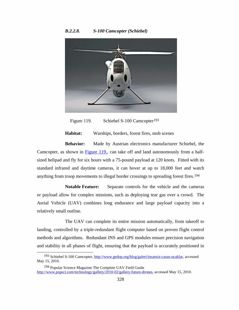
328
B.2.2.8. S-100 Camcopter (Schiebel)
Figure 119. Schiebel S-100 Camcopter193
Habitat: Warships, borders, forest fires, mob scenes
Behavior: Made by Austrian electronics manufacturer Schiebel, the
Camcopter, as shown in Figure 119., can take off and land autonomously from a half-
sized helipad and fly for six hours with a 75-pound payload at 120 knots. Fitted with its
standard infrared and daytime cameras, it can hover at up to 18,000 feet and watch
anything from troop movements to illegal border crossings to spreading forest fires.194
Notable Feature: Separate controls for the vehicle and the cameras
or payload allow for complex missions, such as deploying tear gas over a crowd. The
Aerial Vehicle (UAV) combines long endurance and large payload capacity into a
relatively small outline.
The UAV can complete its entire mission automatically, from takeoff to
landing, controlled by a triple-redundant flight computer based on proven flight control
methods and algorithms. Redundant INS and GPS modules ensure precision navigation
and stability in all phases of flight, ensuring that the payload is accurately positioned in
193 Schiebel S-100 Camcopter, http://www.gedop.org/blog/galeri/insansiz-casus-ucaklar, accessed May 15, 2010.
194 Popular Science Magazine The Complete UAV Field Guide http://www.popsci.com/technology/gallery/2010-02/gallery-future-drones, accessed May 15, 2010.

329
accordance with its tasking. The onboard navigation computer is capable of storing and
managing all waypoint commands, allowing continuous operation independent of the
control station. The datalink receives control inputs from, and transmits position and
payload data to, the control station in real-time. Mission radius is dependent upon the
user-specified ground antenna configuration, and payload weight.195
B.2.2.9. Skylite (BAE Systems)
Figure 120. BAE Systems Skylite196
Habitat: Israeli borders
195 Schiebel “Airial Vehicle” http://www.schiebel.net/pages/cam_air.html, acessed May 15, 2010. 196 BAE Systems Skylite, http://www.gedop.org/blog/galeri/insansiz-casus-ucaklar, accessed May
15, 2010.
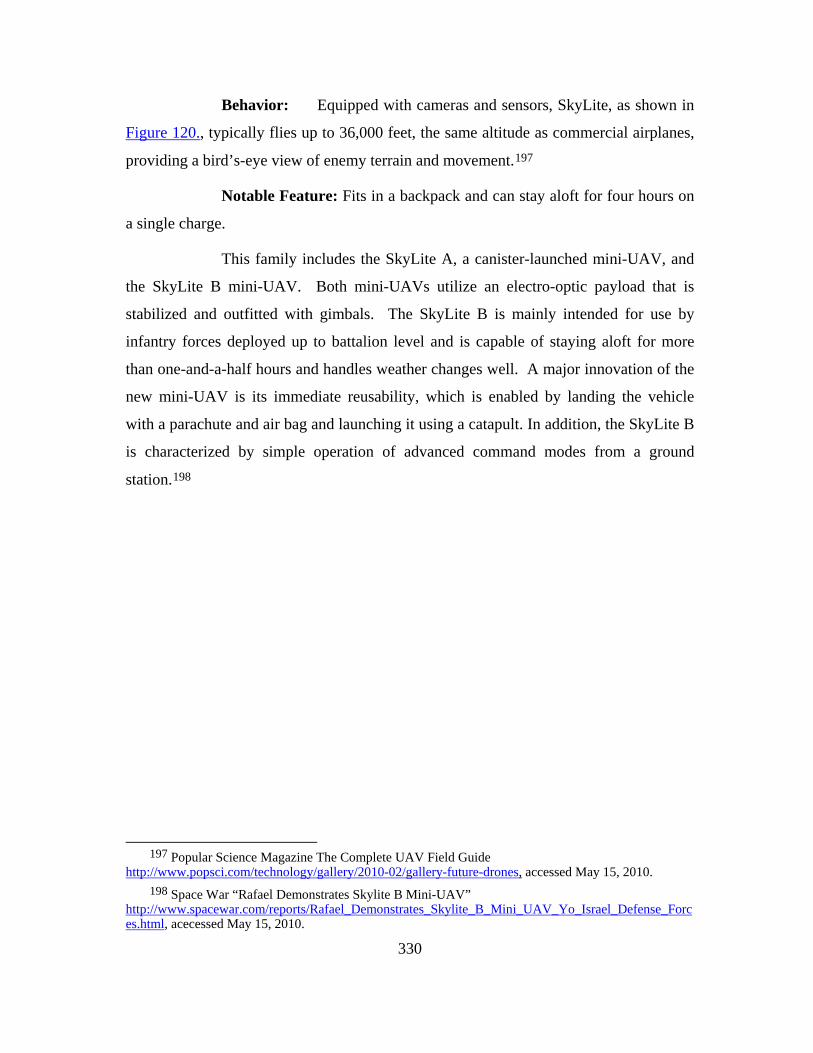
330
Behavior: Equipped with cameras and sensors, SkyLite, as shown in
Figure 120., typically flies up to 36,000 feet, the same altitude as commercial airplanes,
providing a bird’s-eye view of enemy terrain and movement.197
Notable Feature: Fits in a backpack and can stay aloft for four hours on
a single charge.
This family includes the SkyLite A, a canister-launched mini-UAV, and
the SkyLite B mini-UAV. Both mini-UAVs utilize an electro-optic payload that is
stabilized and outfitted with gimbals. The SkyLite B is mainly intended for use by
infantry forces deployed up to battalion level and is capable of staying aloft for more
than one-and-a-half hours and handles weather changes well. A major innovation of the
new mini-UAV is its immediate reusability, which is enabled by landing the vehicle
with a parachute and air bag and launching it using a catapult. In addition, the SkyLite B
is characterized by simple operation of advanced command modes from a ground
station.198
197 Popular Science Magazine The Complete UAV Field Guide
http://www.popsci.com/technology/gallery/2010-02/gallery-future-drones, accessed May 15, 2010. 198 Space War “Rafael Demonstrates Skylite B Mini-UAV”
http://www.spacewar.com/reports/Rafael_Demonstrates_Skylite_B_Mini_UAV_Yo_Israel_Defense_Forces.html, acecessed May 15, 2010.

331
B.2.2.10. MANTIS (BAE Systems)
Figure 121. BAE Systems MANTIS199
Habitat: Up to 40,000 feet above any battlefield, disaster site or
border, relaying intelligence data back to controllers on the ground
Behavior: Can be sent on a mission with a push of a button. From
there, it can calculate flight plans, fly around obstacles, and check in with ground
controllers when it spots something interesting, like smoke or troop movement. At the
end of the mission, it flies home and lands itself. 200
Notable Feature: MANTIS, as shown in Figure 121., is the first in a
new breed of smart drones. A craft that can hone its searches requires less bandwidth
than those that constantly stream images. Mantis can also monitor itself for damage—a
199 BAE Systems MANTIS, http://www.gedop.org/blog/galeri/insansiz-casus-ucaklar, accessed May
15, 2010. 200 Popular Science Magazine The Complete UAV Field Guide
http://www.popsci.com/technology/gallery/2010-02/gallery-future-drones, accessed Ma y15, 2010.

332
sputtering engine, for example—and adjust its electronics to complete a mission. It can
fly up to 345 miles an hour and operate for up to 36 hours. Other Keu features are:201
• MANTIS is BAE Systems’ first all-electric aircraft.
• MANTIS is a fully autonomous next generation unmanned
aircraft system.
• The system is designed to be easily deployable and can be broken
down to fit into a military transport aircraft.
• MANTIS is designed to be a real workhorse with "plug and play"
elements in the mission system and the ability to carry a wide
range of sensors.
• MANTIS can execute its mission with a much reduced need for
human intervention by understanding and reacting to its
environment. Such autonomy increases operational effectiveness
allowing more focus on the mission without the usual concerns
over vehicle control. It also reduces the manpower requirements
and the risk of accidents due to human error and the
communications/data link requirements between the vehicle and
the ground.
201 BAE Systems “Mantis” http://www.baesystems.com/ProductsServices/bae_prod_mantis.html,
accessed May 15, 2001.

333
B.2.2.11. Predator-C Sea Avenger (General Atomics)
Figure 122. General Atomics Predator C Sea Avenger UAV202
Habitat: Flight-operations center for General Atomics Aeronautical
Systems in Palmdale, California.
Behavior: The stealthy jet-powered Avenger, as shown in Figure
122., is packed with 3,000 pounds of surveillance equipment and lethal munitions, such
as laser-guided Hellfire missiles and 500-pound GBU-38 bombs. It can reach speeds of
up to 530 mph, far faster than its spindly predecessors, the Predator and Reaper. With
fuel packed into every available nook of the fuselage, it can loiter above a target for
nearly 20 hours.203
Notable Feature: Its internal weapons bay allows for interchangeable
payloads, such as next-generation wide-area surveillance sensors. General Atomics
202 General Atomics Predator C Sea Avenger UAV, http://air-news.blog.onet.pl/Pierwszy-lot-
Predatora-C,2,ID374472830,n, accessed May 15, 2010. 203 Popular Science Magazine The Complete UAV Field Guide
http://www.popsci.com/technology/gallery/2010-02/gallery-future-drones, accessed May 15, 2010.

334
declines to comment about rumors that the Avenger, is designed to fly to up to
60,000ft.204
B.2.2.12. Zephyr (QinetiQ)
Figure 123. QinetiQ Zephyr205
Habitat: 50,000 feet above Yuma, Arizona, where London-based
manufacturer QinetiQ is testing prototypes.
Notable Feature: Less than 100 pounds, 75-foot wingspan. QinetiQ
has completed the first flight trials of Zephyr, as shown in Figure 123., - a High-
Altitude, Long-Endurance Unmanned Aerial Vehicle (HALE UAV). This ultra-light
204 Flight Global “General Atomics Attracts First Customers for Avenger UAV” http://www.flightglobal.com/articles/2010/02/18/338541/general-atomics-attracts-first-customer-for-avenger-uav-claims.html, accessed May 15, 2010.
205 QinetiQ Zephyr, http://www.gedop.org/blog/galeri/insansiz-casus-ucaklar, accessed May 15, 2010.
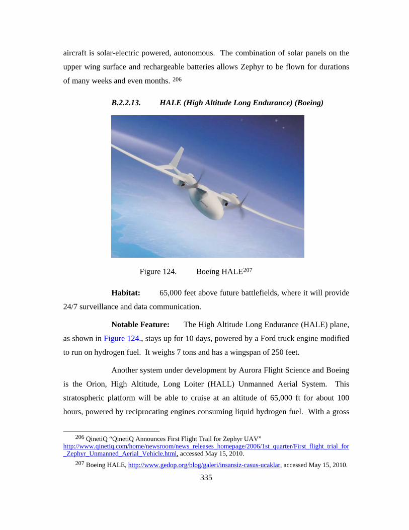
335
aircraft is solar-electric powered, autonomous. The combination of solar panels on the
upper wing surface and rechargeable batteries allows Zephyr to be flown for durations
of many weeks and even months. 206
B.2.2.13. HALE (High Altitude Long Endurance) (Boeing)
Figure 124. Boeing HALE207
Habitat: 65,000 feet above future battlefields, where it will provide
24/7 surveillance and data communication.
Notable Feature: The High Altitude Long Endurance (HALE) plane,
as shown in Figure 124., stays up for 10 days, powered by a Ford truck engine modified
to run on hydrogen fuel. It weighs 7 tons and has a wingspan of 250 feet.
Another system under development by Aurora Flight Science and Boeing
is the Orion, High Altitude, Long Loiter (HALL) Unmanned Aerial System. This
stratospheric platform will be able to cruise at an altitude of 65,000 ft for about 100
hours, powered by reciprocating engines consuming liquid hydrogen fuel. With a gross
206 QinetiQ “QinetiQ Announces First Flight Trail for Zephyr UAV”
http://www.qinetiq.com/home/newsroom/news_releases_homepage/2006/1st_quarter/First_flight_trial_for_Zephyr_Unmanned_Aerial_Vehicle.html, accessed May 15, 2010.
207 Boeing HALE, http://www.gedop.org/blog/galeri/insansiz-casus-ucaklar, accessed May 15, 2010.
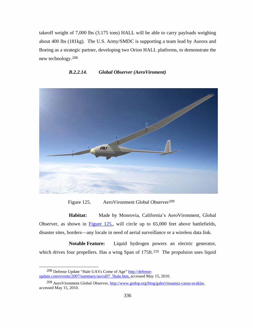
336
takeoff weight of 7,000 lbs (3.175 tons) HALL will be able to carry payloads weighing
about 400 lbs (181kg). The U.S. Army/SMDC is supporting a team lead by Aurora and
Boeing as a strategic partner, developing two Orion HALL platforms, to demonstrate the
new technology.208
B.2.2.14. Global Observer (AeroViroment)
Figure 125. AeroVironment Global Observer209
Habitat: Made by Monrovia, California’s AeroVironment, Global
Observer, as shown in Figure 125., will circle up to 65,000 feet above battlefields,
disaster sites, borders—any locale in need of aerial surveillance or a wireless data link.
Notable Feature: Liquid hydrogen powers an electric generator,
which drives four propellers. Has a wing Span of 175ft.210 The propulsion uses liquid
208 Defense Update “Hale UAVs Come of Age” http://defense-
update.com/events/2007/summary/auvsi07_5hale.htm, accessed May 15, 2010. 209 AeroVironment Global Observer, http://www.gedop.org/blog/galeri/insansiz-casus-ucaklar,
accessed May 15, 2010.
337
hydrogen fuel and fuel cells to drive 8 small rotary engines set along the wings; as noted
above, the goal is 7-day flights. Missions could include:
• Wide-area “persistent stare” reconnaissance for defense and
homeland security missions, probably using radars rather than
optical payloads as the primary sensors;
• Signals and communications intercepts over a wide area, for long
periods of time;
• Low-cost, rapidly deployable augmentation for telecom
bandwidth, and even GPS;
• Hurricane/storm tracking, weather monitoring, wildfire detection,
and sustained support for relief operations;
• Aerial imaging/mapping, for defense uses or for civilian
commercial and environmental monitoring, agriculture crop
management and harvesting optimization.211
210 Popular Science Magazine The Complete UAV Field Guide
http://www.popsci.com/technology/gallery/2010-02/gallery-future-drones, accessed May 15, 2010. 211 Defense Industry Daily “ Aerovirnments Global Observer, Flying High, Again”
http://www.defenseindustrydaily.com/aerovironments-global-observer-flying-high-again-03902/, accessed May 15, 2010.
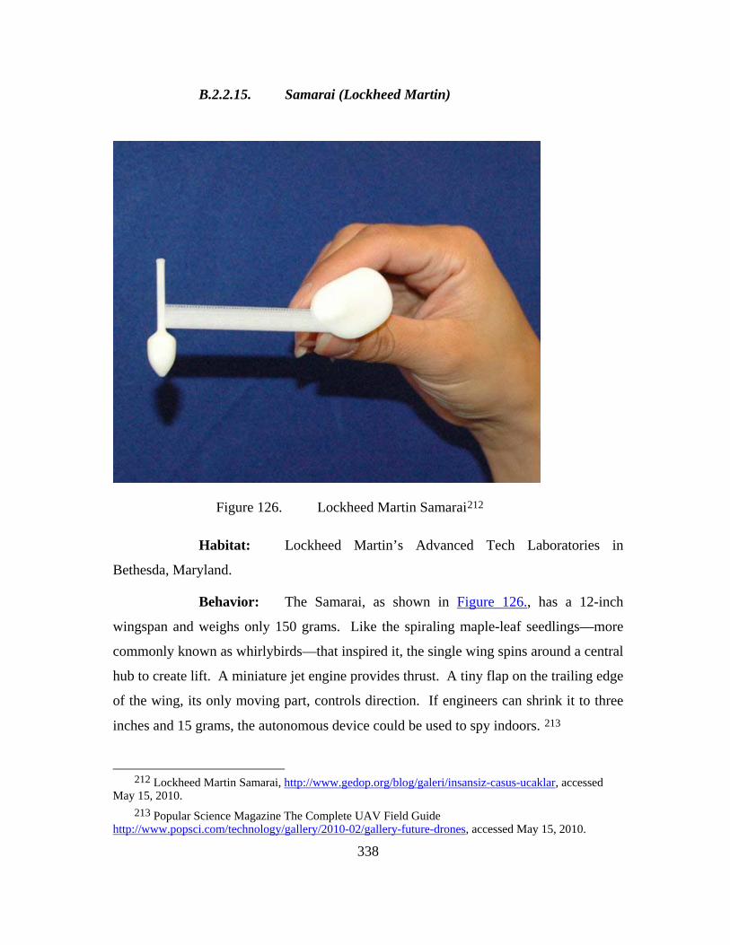
338
B.2.2.15. Samarai (Lockheed Martin)
Figure 126. Lockheed Martin Samarai212
Habitat: Lockheed Martin’s Advanced Tech Laboratories in
Bethesda, Maryland.
Behavior: The Samarai, as shown in Figure 126., has a 12-inch
wingspan and weighs only 150 grams. Like the spiraling maple-leaf seedlings—more
commonly known as whirlybirds—that inspired it, the single wing spins around a central
hub to create lift. A miniature jet engine provides thrust. A tiny flap on the trailing edge
of the wing, its only moving part, controls direction. If engineers can shrink it to three
inches and 15 grams, the autonomous device could be used to spy indoors. 213
212 Lockheed Martin Samarai, http://www.gedop.org/blog/galeri/insansiz-casus-ucaklar, accessed
May 15, 2010. 213 Popular Science Magazine The Complete UAV Field Guide
http://www.popsci.com/technology/gallery/2010-02/gallery-future-drones, accessed May 15, 2010.

339
Notable Feature: In the future, a camera mounted on the central hub
that snaps a picture once every rotation will collect enough images to stitch together full-
motion video. Diet: Today, batteries; but engineers plan to feed the next version
propane, which is light and readily available in the military supply chain.214
214 Geekology “Lockeed Martin’s Samurai Monocopter “
http://www.geekologie.com/2009/09/crazy_lockheed_martins_samurai.php, accessed May 15, 2010.

340
B.3. UNMANNED SURFACE VEHICLES
B.3.1. Protector (Rafael/BAE Systems)
Maritime Unmanned Systems are a newer field than UAV, but they are a
growing field. USV can perform everything from port, harbor, and one Navy specific
mission of Oil Platform security to combat operation with a battlegroup or surface task
force. The Protector, as shown in Figure 127., is one system under testing was originally
designed by the Israeli Company Rafael. Rafael has teamed with BAE (British
Aerospace) Systems and Lockheed Martin and Rafael are teamed for product production
and all other program developments with Lockheed Martin.215
Figure 127. Rafael Protector216
215 Protector, available from http://www.lockheedmartin.com/, accessed January 10, 2010. 216 Rafael Protector, http://snafu-solomon.blogspot.com/2009/12/protector-usvsolution-to-
littoral.html, accessed May 15 ,2010.
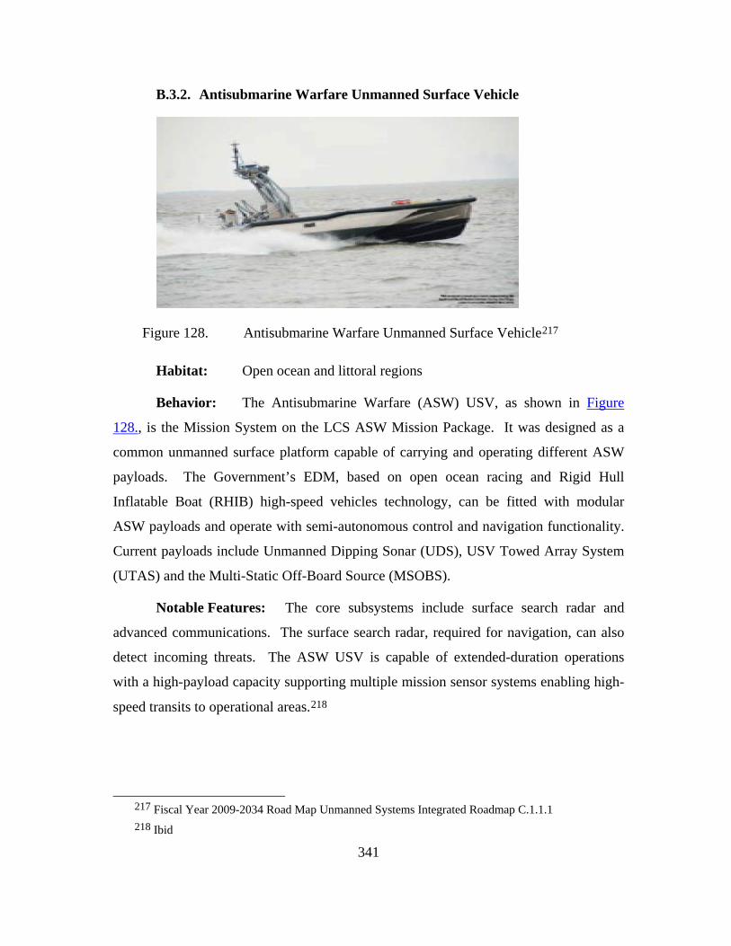
341
B.3.2. Antisubmarine Warfare Unmanned Surface Vehicle
Figure 128. Antisubmarine Warfare Unmanned Surface Vehicle217
Habitat: Open ocean and littoral regions
Behavior: The Antisubmarine Warfare (ASW) USV, as shown in Figure
128., is the Mission System on the LCS ASW Mission Package. It was designed as a
common unmanned surface platform capable of carrying and operating different ASW
payloads. The Government’s EDM, based on open ocean racing and Rigid Hull
Inflatable Boat (RHIB) high-speed vehicles technology, can be fitted with modular
ASW payloads and operate with semi-autonomous control and navigation functionality.
Current payloads include Unmanned Dipping Sonar (UDS), USV Towed Array System
(UTAS) and the Multi-Static Off-Board Source (MSOBS).
Notable Features: The core subsystems include surface search radar and
advanced communications. The surface search radar, required for navigation, can also
detect incoming threats. The ASW USV is capable of extended-duration operations
with a high-payload capacity supporting multiple mission sensor systems enabling high-
speed transits to operational areas.218
217 Fiscal Year 2009-2034 Road Map Unmanned Systems Integrated Roadmap C.1.1.1 218 Ibid

342
B.3.3. Mine Counter Measures (MCM)
Figure 129. Mine Counter Measures (MCM)219
Habitat: Littoral and river regions
Behavior: The Mine Counter Measures (MCM) Unmanned Surface Vehicle
(USV), as shown in Figure 129., is the Mission System on the LCS MCM Mission
Package. It was selected as the unmanned platform to “get the man out of the
minefield” and will be used to tow the Unmanned Surface Sweep System (USSS) to
clear minefields.
Notable Features: USV core system controller and communications were
developed and integrated at the Naval Surface Warfare Center (NSWC) Panama City.
The USV Platform Controller for LCS is compliant with the Joint Architecture for
Unmanned Systems (JAUS). Full Functional Tests were completed at Ft. Monroe, VA
in June 2008 and validated Functional Requirements.220
219 Fiscal Year 2009-2034 Road Map Unmanned Systems Integrated Roadmap C.1.1.2 220 Ibid.

343
B.3.4. SEAFOX
Figure 130. SEAFOX221
Habitat: Riverine and Maritime Interdiction Operations as well as port
security.
Behavior: The SEAFOX USV, as shown in Figure 130., will provide a
remote, unmanned ISR capability supporting multiple mission areas.
Notable Features: The SEAFOX USV has a JP-5 jet engine and a payload
consisting of a Command and Control, Communications, and Intelligence (C3I) system.
The C3I payload has an amplified military band command and control radio,
autonomous way-point navigation, amplified communications, and intelligence
consisting of: wide bandwidth video, object tracking and dejitter software, digital zoom
Infra-Red (IR) camera, digital zoom daylight color camera, 3x70 degree navigation
cameras, remote camera operation station, remote ground station, remotely activated
flood lighting, remotely activated hailer/announcement system, and navigation/ strobe
safety lights. In particular, SEAFOX 1 will have enhanced communications ability with
4 bands (2 MIL, 2 ISM), LCS bands, Unmanned Aircraft System (UAS)
221 SEAFOX, http://www.nps.edu/Academics/Centers/CAVR/Vehicles/SeaFox.html, accessed
Jaunuary 10, 2010.
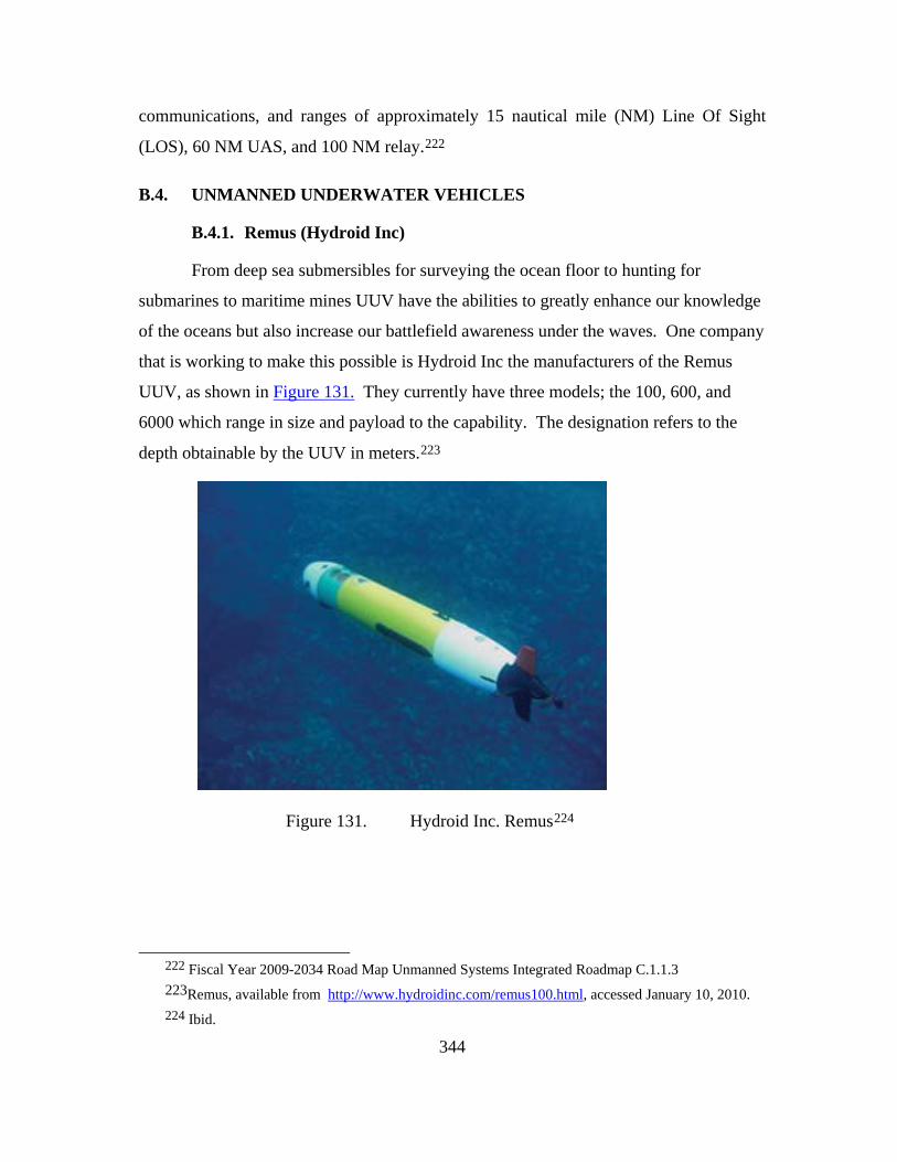
344
communications, and ranges of approximately 15 nautical mile (NM) Line Of Sight
(LOS), 60 NM UAS, and 100 NM relay.222
B.4. UNMANNED UNDERWATER VEHICLES
B.4.1. Remus (Hydroid Inc)
From deep sea submersibles for surveying the ocean floor to hunting for
submarines to maritime mines UUV have the abilities to greatly enhance our knowledge
of the oceans but also increase our battlefield awareness under the waves. One company
that is working to make this possible is Hydroid Inc the manufacturers of the Remus
UUV, as shown in Figure 131. They currently have three models; the 100, 600, and
6000 which range in size and payload to the capability. The designation refers to the
depth obtainable by the UUV in meters.223
Figure 131. Hydroid Inc. Remus224
222 Fiscal Year 2009-2034 Road Map Unmanned Systems Integrated Roadmap C.1.1.3 223Remus, available from http://www.hydroidinc.com/remus100.html, accessed January 10, 2010. 224 Ibid.
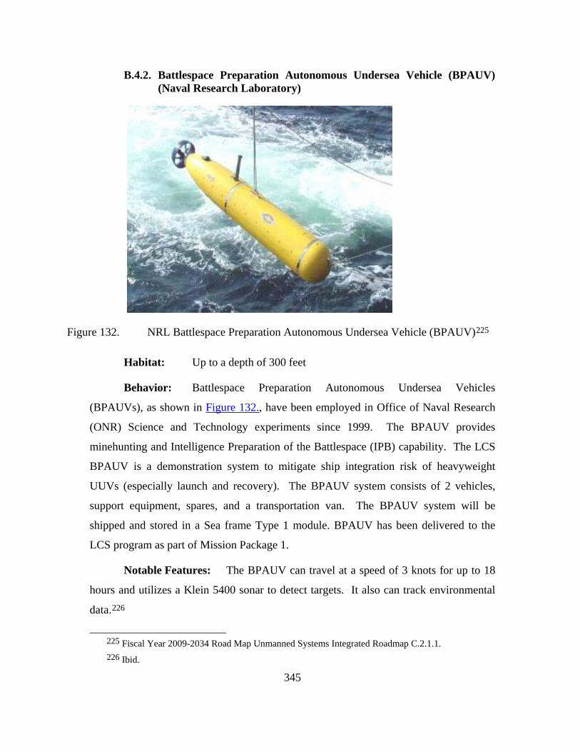
345
B.4.2. Battlespace Preparation Autonomous Undersea Vehicle (BPAUV) (Naval Research Laboratory)
Figure 132. NRL Battlespace Preparation Autonomous Undersea Vehicle (BPAUV)225
Habitat: Up to a depth of 300 feet
Behavior: Battlespace Preparation Autonomous Undersea Vehicles
(BPAUVs), as shown in Figure 132., have been employed in Office of Naval Research
(ONR) Science and Technology experiments since 1999. The BPAUV provides
minehunting and Intelligence Preparation of the Battlespace (IPB) capability. The LCS
BPAUV is a demonstration system to mitigate ship integration risk of heavyweight
UUVs (especially launch and recovery). The BPAUV system consists of 2 vehicles,
support equipment, spares, and a transportation van. The BPAUV system will be
shipped and stored in a Sea frame Type 1 module. BPAUV has been delivered to the
LCS program as part of Mission Package 1.
Notable Features: The BPAUV can travel at a speed of 3 knots for up to 18
hours and utilizes a Klein 5400 sonar to detect targets. It also can track environmental
data.226
225 Fiscal Year 2009-2034 Road Map Unmanned Systems Integrated Roadmap C.2.1.1. 226 Ibid.

346
B.4.3. Littoral Battlespace Sensing – Autonomous Undersea Vehicle (LBSAUV)
Figure 133. Littoral Battlespace Sensing – Autonomous Undersea Vehicle (LBSAUV)227
Habitat: Maximum depth of 500 meters
Behavior: The Littoral Battlespace Sensing – Autonomous Undersea
Vehicle (LBS-AUV), as shown in Figure 133., is the acquisition POR intended to
increase the survey footprint of the T-AGS 60 Multi-Mission Survey Ship, as well as
allow clandestine military surveys to be conducted at a greater standoff range, thereby
decreasing the risk to the ship and crew.
Notable Features: Can travel at 4 knots for a maximum endurance of 24
hours. Utilizes a Multibeam Bathymetry, Side Scan Sonar, CTD, Optical.228
227 Fiscal Year 2009-2034 Road Map Unmanned Systems Integrated Roadmap C.2.1.2. 228 Ibid
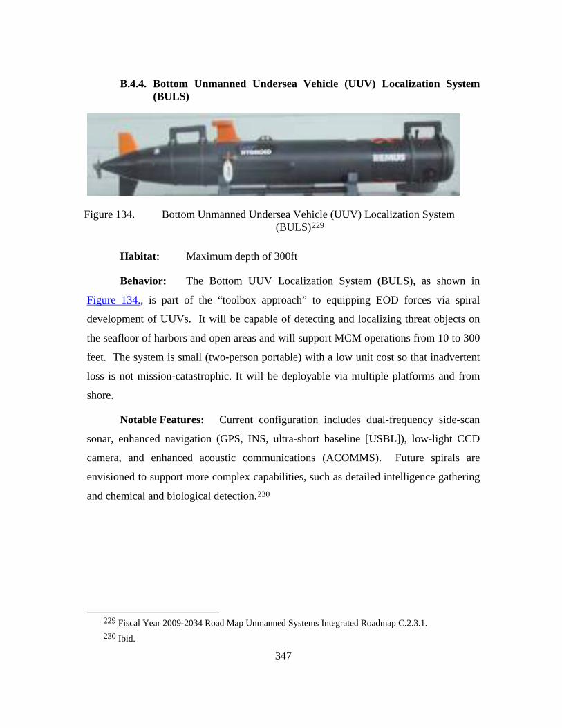
347
B.4.4. Bottom Unmanned Undersea Vehicle (UUV) Localization System (BULS)
Figure 134. Bottom Unmanned Undersea Vehicle (UUV) Localization System (BULS)229
Habitat: Maximum depth of 300ft
Behavior: The Bottom UUV Localization System (BULS), as shown in
Figure 134., is part of the “toolbox approach” to equipping EOD forces via spiral
development of UUVs. It will be capable of detecting and localizing threat objects on
the seafloor of harbors and open areas and will support MCM operations from 10 to 300
feet. The system is small (two-person portable) with a low unit cost so that inadvertent
loss is not mission-catastrophic. It will be deployable via multiple platforms and from
shore.
Notable Features: Current configuration includes dual-frequency side-scan
sonar, enhanced navigation (GPS, INS, ultra-short baseline [USBL]), low-light CCD
camera, and enhanced acoustic communications (ACOMMS). Future spirals are
envisioned to support more complex capabilities, such as detailed intelligence gathering
and chemical and biological detection.230
229 Fiscal Year 2009-2034 Road Map Unmanned Systems Integrated Roadmap C.2.3.1. 230 Ibid.
348
B.5. UNMANNED GROUND VEHICLES
B.5.1. UGV Light
B.5.1.1. Soldier UGV (SUGV)
Habitat: Urban and subterranean operating environments
Behavior: The Soldier UGV (SUGV) is a man-packable small robot
system, weighing less than 30 lbs, used to remotely investigate the threat obstacles,
structures and the structural integrity of facilities and utilities. SUGV systems will be
highly mobile for dismounted forces and will be capable of being re-configured for other
missions by adding or removing sensors, modules, mission payloads, and/or subsystems.
Notable Features: The Small Unmanned Ground Vehicle (SUGV) is
a remotely operated, man-packable, robotic vehicle. This is a small man-portable
vehicle with modular payloads that will allow the SUGV to perform:
• Reconnaissance
• Surveillance
• Assault231
B.5.1.2. Combined Operations Battlefield Robotic Asset (COBRA)
Habitat: COBRA is a Soldier UGV (SUGV) system small enough
to be carried by one man over long distances and provide significant increase in
effectiveness for small unit operations.
Behavior: The COBRA will be carried by one soldier or
disassembled and carried by two (8-30 lbs.). It will be designed for modular multi-
mission payloads and be able to operate 4-12 hours. The vehicle will have
semiautonomous control and navigation. With on-board sensors, it will be able to:
• Detect and neutralize booby traps and AP mines
231 Ibid.

349
• Detect NBC presence
• Deploy smoke
Notable Features: Combined Operations Battlefield Robotic Asset
[COBRA] is coincident with the Soldier UGV (SUGV) component of the FCS and will
be an integrated node on FCS network of systems. The COBRA program is coincident
with and supports the Army Future Combat System SUGV.232
B.5.1.3. Man Transportable Robotic System (MTRS)
Man Transportable Robotic System [MTRS] consists primarily of an
operator control unit (OCU) and a teleoperated vehicle. The system components will be
small and light enough to be carried as a single load by a two-person team for 500
meters over semi-rugged terrain. The primary mission is reconnaissance, and the system
will be enhanced to perform other EOD tasks.233
232 Combined Operations Battlefield Robotic Asset (COBRA), http://www.globalsecurity.org/military/systems/ground/fcs-soldier.htm, accessed May 15, 2010.
233 Man Transportable Robotic System (MTRS), http://www.globalsecurity.org/military/systems/ground/fcs-soldier.htm, accessed May 15, 2010.

350
B.5.1.4. Dragon Runner
Figure 135. Dragon Runner234
Habitat: Urban environment
Behavior: Dragon Runner, as shown in Figure 135., is a small, four-
wheeled, rear-wheel drive, front-wheel steer, man-portable mobile ground sensor
designed to increase situational awareness. It will give tactical Marine units the
capability to “see around the corner” in an urban environment.
Notable Features: At 15.5 inches long, 11.25 inches wide and five
inches high, Dragon Runner will fit inside the standard Modular, Light Weight, Load
Carrying Equipment (MOLLE) Patrol Pack. The total system weighs 16 pounds. A
non-active and invertible suspension enables Dragon Runner to be tossed through
windows, up stairs or over walls for a rapid deployment capability. The user interface
features a four-inch video display and home-gaming type controller for vehicle
234 Dragon Runner, http://www.globalsecurity.org/military/systems/ground/dragon-runner.htm,
accessed May 15, 2010.

351
manipulation. The entire system uses standard military radio-type batteries for its power
supply.235
B.5.1.5. Mesa Associates’ Tactical Integrated Light-Force Deployment Assembly (MATILDA)
Figure 136. Mesa Associates’ Tactical Integrated Light-Force Deployment Assembly (MATILDA)236
Habitat: Urban environments
Behavior: Operated by radio remote MATILDA, as shown in Figure
136., is a reconnaissance robot used in the role as a point man and is capable of
breaching doors or walls with explosives
Notable Features: It weights 40 lbs. and measures 26”L x 20”W x
12”H (platform only). Optional attachments include a small trailer (400 lbs. capacity), a
manipulator arm, and a remotely detachable breaching mechanism. Key elements of
these evaluations have resulted in the development of a robotic manipulator arm,
operator control unit upgrade, light kit, 4-wheel trailer, larger monitor, and an upgraded
radio system for extended range.237
235 Ibid. 236 MATILDA, http://www.globalsecurity.org/military/systems/ground/matilda.htm,
accessed May 15, 2010. 237 Ibid.

352
B.5.2. UGV Medium
B.5.2.1. Metal Storm
UGV can be used for anything from surveillance, EOD bomb detection
and disposal, to combat operations. The US Navy could make use of UGV for EOD and
surveillance. Other organizations can make use of UGV for surveillance, re-supply, and
even combat integrated with manned forces in the field. One example is the Talon
UGV, as shown in Figure 137., manufactured by Metal Storm.238
Figure 137. Metal Storm Talon UGV239
UGVs have not received a lot of the spotlight in recent years because
there have not been a lot of breakthroughs in the area of artificial intelligence to handing
the amount of obstacles for operations on the ground. In the following section four
categories of UGVs have been examined and presently in use throughout the military.
238 Talon UGV, available from http://www.metalstorm.com/ and
http://www.globalsecurity.org/military/systems/ground/talon.htm , accessed January 10, 2010.
239 Talon UGV, http://www.engadget.com/2005/03/30/metal-storms-talon-ugv-grenade-launcher/, accessed January 10, 2010.

353
B.5.2.2. Remote Detection, Challenge, and Response System (REDCAR) (ARFL)
Figure 138. ARFL Remote Detection, Challenge, and Response System (REDCAR)240
Habitat: The REDCAR program, as shown in Figure 138., focuses
on the application of mobile unmanned ground systems to support and augment security
force personnel in the perimeter defense of Air Force installations and forward deployed
units.
Behavior: The AFRL REDCAR system will consist of a network of
robotic platforms integrated with existing security force sensors and Tactical, Area
Security System (TASS). The REDCAR system will have limited simulation and
modeling capabilities to interact with the current AFFPB modeling systems. All
components and platforms in the REDCAR system will be capable of communication
using JAUS for system interoperability and control.
Notable Features: REDCAR will use at least three different robotic
platforms:
240 REDCAR, http://www.globalsecurity.org/military/systems/ground/redcar.htm, accessed May 15,
2010.

354
• Surveillance platform
• Engagement platform
• Small-scale platform for limited access areas.241
B.5.2.3. Gladiator Tactical Unmanned Ground Vehicle
Figure 139. Gladiator242
Habitat: Battlefield, multi-terrain vehicle
Behavior: Gladiator, as shown in Figure 139., will perform
scout/surveillance, nuclear biological and chemical reconnaissance, direct fire, and
personnel obstacle breaching missions in its basic configuration.
241 Ibid. 242 Gladiator, http://www.globalsecurity.org/military/systems/ground/gladiator.htm , accessed May
15, 2010.

355
Notable Features: Essential Functions of the Gladiator system
include:243
• Day/night remote visual acuity equal to that of an individual
Marine using current image intensifying or thermal devices
• Battlefield mobility capable of supporting dismounted units in all
environments, including MOUT rubble
• Modular design and incorporation of standard interfaces for
attachment of future mission payloads
• Remain operable and mission capable after being impacted by
multiple 7.62mm small arms rounds at zero standoff distance
B.5.2.4. Mobile Detection Assessment and Response System (MDARS)
Figure 140. Mobile Detection Assessment and Response System (MDARS)244
243 Ibid. 244 MDARS, http://www.globalsecurity.org/military/systems/ground/mdars.htm, accessed May 15,
2010.

356
Habitat: indoor and outdoor storage facilities
Behavior: The Mobile Detection Assessment and Response System
(MDARS), as shown in Figure 140., is a joint Army-Navy development effort to provide
an automated intrusion detection and inventory assessment capability for use in DoD
warehouses and storage sites. The MDARS goal is to provide multiple mobile platforms
that perform random patrols within assigned areas of warehouses and storage sites.245
Notable Features: Very compact movement and can return to a
charging station autonomously.
B.5.2.5. Remote Ordnance Neutralization System (RONS)
Figure 141. Remote Ordnance Neutralization System (RONS)246
245 Ibid. 246 RONS, http://www.globalsecurity.org/military/systems/ground/mdars.htm, accessed
May 15, 2010.
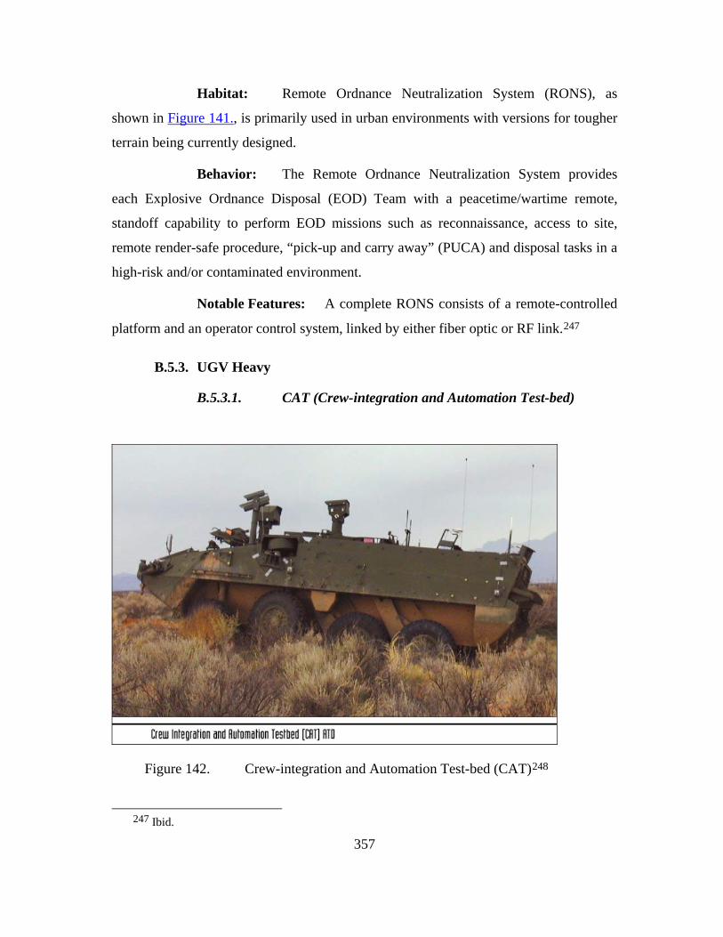
357
Habitat: Remote Ordnance Neutralization System (RONS), as
shown in Figure 141., is primarily used in urban environments with versions for tougher
terrain being currently designed.
Behavior: The Remote Ordnance Neutralization System provides
each Explosive Ordnance Disposal (EOD) Team with a peacetime/wartime remote,
standoff capability to perform EOD missions such as reconnaissance, access to site,
remote render-safe procedure, “pick-up and carry away” (PUCA) and disposal tasks in a
high-risk and/or contaminated environment.
Notable Features: A complete RONS consists of a remote-controlled
platform and an operator control system, linked by either fiber optic or RF link.247
B.5.3. UGV Heavy
B.5.3.1. CAT (Crew-integration and Automation Test-bed)
Figure 142. Crew-integration and Automation Test-bed (CAT)248
247 Ibid.

358
Habitat: Wide spectrum of terrain can be covered on the battlefield,
mobility of a tank or transport vehicle.
Behavior: The goal of the Crew-integration and Automation Test bed
(CAT), as shown in Figure 142., Advanced Technology Demonstration (ATD) is to
demonstrate a multi-mission capable two-man crew station platform concept, which will
be integrated into a C-130 transportable chassis supporting the Army's objective force.
This program focuses on an improved soldier machine interface (SMI) design using
indirect vision driving and automated decision aids, an advanced electronic architecture
design/network topology, and embedded simulation. By demonstrating these advanced
technologies and added capabilities, the CAT ATD will prove out technology readiness
to sufficiently transition and integrate hardware and software components into the
Future Combat Systems (FCS) demonstrator.
Notable Features: Key Program Objectives:
• Design an advanced 2-man crew station for a system < 20 tons
incorporating the FCS fight, carrier, reconnaissance, and C2 of
unmanned systems
• Provide technology readiness sufficient to enable integration into
future FCS system demonstrator
o Soldier Machine Interface technology
o Indirect Vision
o Speech Recognition
o Crewman’s Associate Interface
o Helmet Mounted Display vs. Panoramic Displays
o Decision Aids (Route Planning, Driving, Mission, etc…)
• Embedded simulation while on-the-move
• Advanced vehicle architecture
• Prove out technology developments using a FCS class chassis to
test against our exit criteria
248 CATS, http://www.globalsecurity.org/military/systems/ground/cat.htm, accessed May 15, 2010.

359
Technologies to be investigated include both traditional Soldier-Machine
Interface (SMI) technologies (e.g., helmet-mounted displays, head trackers, panoramic
displays, speech recognition, etc.) and robotics technologies (e.g., intelligent driving
decision aids, semi-autonomous driving, automated route planning, etc.). Workload
analysis performed under the CAT program indicates that the driving aids and
automation technologies are key to achieving two-person operation of future systems.
The crew stations and technologies were integrated into an IAV and demonstrated over
fight, scout and carrier mission scenarios in FY03 and in FY04.249
B.5.3.2. Cooperative Unmanned Ground Attack Robots (COUGAR)
Figure 143. Cooperative Unmanned Ground Attack Robots (COUGAR)250
249 Ibid. 250 COUGAR, http://www.globalsecurity.org/military/systems/ground/cougar.htm, accessed May 15,
2010.

360
Habitat: Wide spectrum of terrain can be covered on the battlefield,
mobility of a tank or transport vehicle.
Behavior: The Cooperative Unmanned Ground Attack Robots
(COUGAR), shown in Figure 143., is a technology effort to investigate and demonstrate
multiple unmanned systems cooperating for the purpose of delivering lethal fires. As
such, the COUGAR is not a system, but a lethal capability that could transition into a
variety of unmanned system programs including the FCS and Gladiator.
Notable Features: Phase I of the COUGAR project was completed in
FY01. During Phase I, a XUV based robot with a RSTA package and a Javelin missile
were simulated. A demonstration of the Phase I system was completed with the
successful launch of both 19 Light Antitank Weapon (LAW) rockets and 1 Javelin
missile. Phase II of the COUGAR is currently under way.
The COUGAR Phase II demonstration system is composed of a
command vehicle that will host the Operator Control Unit and a single operator. The
Killer Robot will be a XUV-based robot that will carry HELLFIRE missiles. The
Hunter Robot will be a XUV-based robot that will carry a day/night reconnaissance
payload, a laser designation system, and an organic Unmanned Air Vehicle (UAV). The
organic UAV will be the Compact Air Vehicle – Shooter Linker (CAV-SL) being
developed under an Army Aviation and Missile Command 6.2 program. Before launch,
the operator programs the CAV-SL’s flight path.
COUGAR is an outgrowth of an Aviation and Missile Research,
Development, and Engineering Center (AMRDEC) 6.2 program called Robotic
Applications for Modular Payloads (RAMP). RAMP was a technology project designed
to investigate technologies that support dynamic plug-and-play payloads. The
warfighter is then able to reconfigure a robotic system for a different mission simply by
swapping payloads. The robotic systems will identify the payload and configure the
OCU to support that payload.251
251 Ibid.
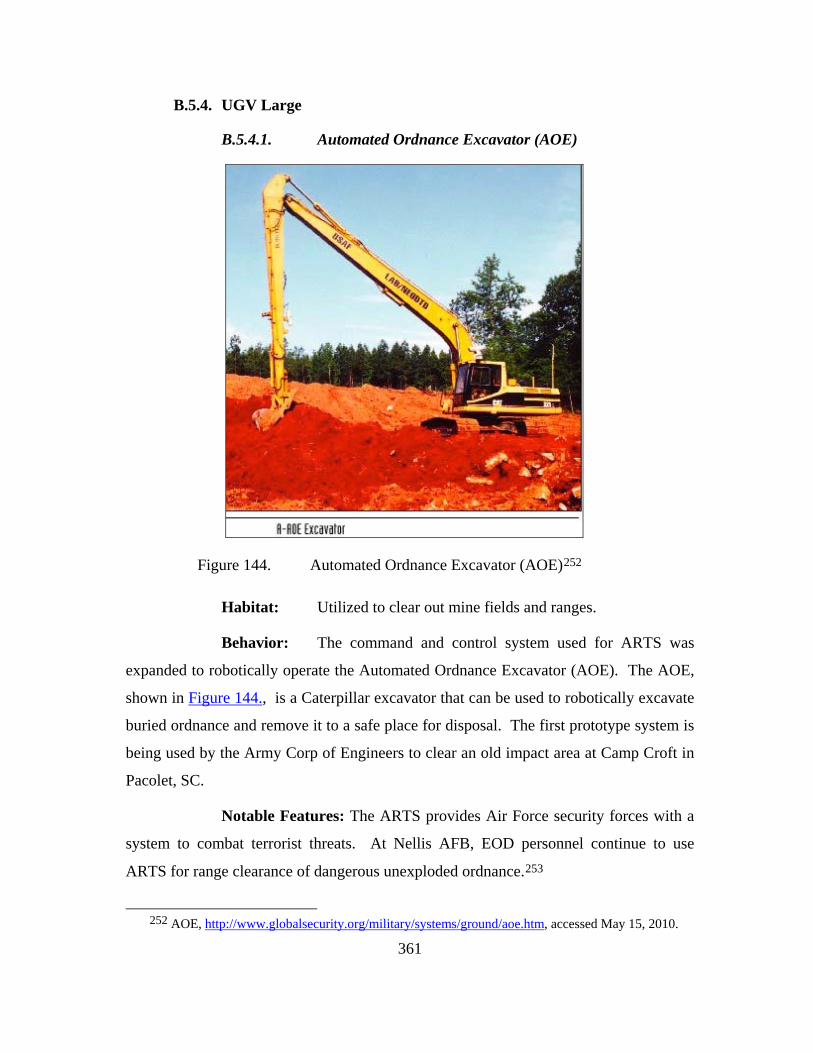
361
B.5.4. UGV Large
B.5.4.1. Automated Ordnance Excavator (AOE)
Figure 144. Automated Ordnance Excavator (AOE)252
Habitat: Utilized to clear out mine fields and ranges.
Behavior: The command and control system used for ARTS was
expanded to robotically operate the Automated Ordnance Excavator (AOE). The AOE,
shown in Figure 144., is a Caterpillar excavator that can be used to robotically excavate
buried ordnance and remove it to a safe place for disposal. The first prototype system is
being used by the Army Corp of Engineers to clear an old impact area at Camp Croft in
Pacolet, SC.
Notable Features: The ARTS provides Air Force security forces with a
system to combat terrorist threats. At Nellis AFB, EOD personnel continue to use
ARTS for range clearance of dangerous unexploded ordnance.253
252 AOE, http://www.globalsecurity.org/military/systems/ground/aoe.htm, accessed May 15, 2010.

362
B.5.4.2. CRUSHER
Figure 145. CRUSHER254
Habitat: Wide spectrum of terrain can be covered on the battlefield,
mobility of a tank or transport vehicle. Rough terrain is its specialty.
Behavior: The 6.5-ton "Crusher", shown in Figure 145., combines
the strength and mobility of a predecessor known as Spinner with NREC-developed
autonomy capabilities to create an extremely robust, unmanned vehicle that can function
on its own in challenging off-road terrain.255
Notable Features: Currently still being tested, by its inventing team at
Carnegie Mellon University's National Robotics Engineering Center (NREC) in the
School of Computer Science's Robotics Institute.
253 Ibid. 254 Crusher, http://www.physorg.com/news65522328.html, accessed May 15, 2010. 255 Ibid.

363
B.6. UNMANNED OUTER SPACE VEHICLES
B.6.1. Space X-37B (Boeing)
Figure 146. Boeing X-37B256
256 X-37B, http://www.space.com/php/multimedia/imagedisplay/img_display.php?pic=X37b-
spaceplane-100416-02.jpg&cap=Diagram+of+the+U.S.+Air+Force's+X-37B+Orbital+Test+Vehicle.+<a+href%3Dhttp://www.space.com/missionlaunches/secret-x-37b-details-revealed-100417.html>Full+Story</a>.+Some+new+details+have+emerged+on+the+secretive+space+plane's+April+2010+launch+test+flight.+Graphic+by+Karl+Tate., accessed May 15, 2010.

364
Figure 147. Boeing X-37B257
Habitat: Earth’s orbit, space.
Behavior: It is powered by a solar cells and lithium-ion batteries, unlike a
traditional craft which is powered by a fuel cell system. It has a large engine at the rear
for orbit changing. The space plane is also reusable.
Notable Features: The X-37B, shown in Figure 146. and Figure 147., is 9m
long (29ft) and has a wingspan of 4.5m (15ft), making it a quarter of the size of a normal
Shuttle.
Built by Boeing's Phantom Works division, the X-37 program was originally
headed by NASA. It was later handed over to the Pentagon's research and development
arm and then to a secretive Air Force unit.258
Airforce Official Site259
257 X-37B, Daily Mail “ Unmanned Space Shuttle Launched”
http://www.dailymail.co.uk/news/worldnews/article-1268138/X-37B-unmanned-space-shuttle-launched-tonight.html, accessed May 15, 2010.
258 Ibid. 259 X-37B, http://www.af.mil/news/story.asp?storyID=123032226 accessed May 15, 2010.

365
THIS PAGE INTENTIONALLY LEFT BLANK
366
INITIAL DISTRIBUTION LIST
1. Defense Technical Information Center Ft. Belvoir, Virginia
2. Dudley Knox Library Naval Postgraduate School Monterey, California
3. Navy Expeditionary Combat Command (NECC) 1575 Gator Blvd Virginia Beach, VA 23459
4. Mr. Charles Werchado Chief of Naval Operations 2000 Navy Pentagon N8FB Washington, DC 20350-2000
5. Mr. James McCarthy Chief of Naval Operations 2000 Navy Pentagon N8B Washington, DC 20350-2000

367
THIS PAGE INTENTIONALLY LEFT BLANK