an interconnect-centric design flow for nanometer...
TRANSCRIPT

An Interconnect-Centric Design Flow for Nanometer Technologies
Jason CongUCLA Computer Science Department
Email: [email protected]: 310-206-2775
http://cadlab.cs.ucla.edu/~cong
Jason Cong 10/17/01 2
Outline
?Global interconnects in nanometer technologies
? Interconnect-centric design flow?Physical hierarchy generation?Motivation?Approaches
?Results and on-going work
Jason Cong 10/17/01 3
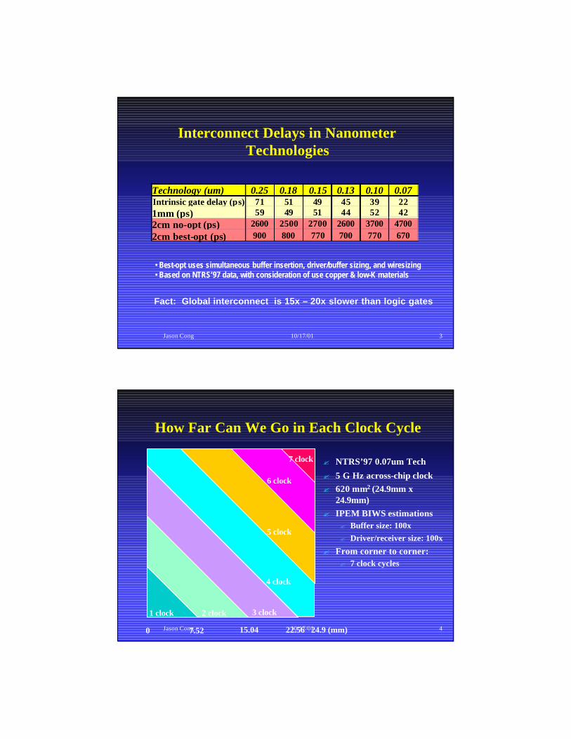
Interconnect Delays in Nanometer Technologies
Technology (um) 0.25 0.18 0.15 0.13 0.10 0.07 Intrinsic gate delay (ps) 71 51 49 45 39 22 1mm (ps) 59 49 51 44 52 42 2cm no-opt (ps) 2600 2500 2700 2600 3700 4700 2cm best-opt (ps) 900 800 770 700 770 670
• Best-opt uses simultaneous buffer insertion, driver/buffer sizing, and wiresizing• Based on NTRS’97 data, with consideration of use copper & low-K materials
Fact: Global interconnect is 15x – 20x slower than logic gates
Jason Cong 10/17/01 4
How Far Can We Go in Each Clock Cycle
7.52 15.04 22.56 24.9 (mm)0
1 clock 2 clock 3 clock
4 clock
5 clock
6 clock
7 clock ? NTRS’97 0.07um Tech
? 5 G Hz across-chip clock? 620 mm2 (24.9mm x
24.9mm)? IPEM BIWS estimations
? Buffer size: 100x? Driver/receiver size: 100x
? From corner to corner:? 7 clock cycles

Jason Cong 10/17/01 5
Two Important Implications
? Interconnects determine the system performance
? Need multiple clock cycles to cross the global interconnects in giga-hertz designs
Interconnect/communication-centric design methodology
Pipelining/retiming on global interconnects
Jason Cong 10/17/01 6
Interconnect-Centric Design Methodology
deviceinterconnect
device interconnect
ProgramsData/Objects
Programs Data/Objects
? Proposed transition
? Analogy
device/function centric interconnect/communication centric
Jason Cong 10/17/01 7
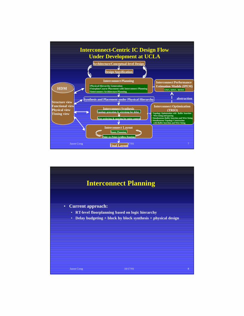
Interconnect-Centric IC Design Flow Under Development at UCLA
Architecture/Conceptual-level Design
Design Specification
Final Layout
abstractionStructure viewFunctional viewPhysical viewTiming view
HDM
Synthesis and Placement under Physical Hierarchy
Interconnect Planning•Physical Hierarchy Generation•Foorplan/Coarse Placement with Interconnect Planning•Interconnect Architecture Planning
Interconnect Optimization(TRIO)
• Topology Optimization with Buffer Insertion• Wire sizing and spacing• Simultaneous Buffer Insertion and Wire Sizing• Simultaneous Topology Construction
with Buffer Insertion and Wire Sizing
Interconnect LayoutRoute Planning
Point-to-Point Gridless Routing
Interconnect PerformanceEstimation Models (IPEM)
•OWS, SDWS, BISWS
Interconnect SynthesisTopology genration & wiresizng for delay
Wire ordering & spacing for noise control
Jason Cong 10/17/01 8
Interconnect Planning
• Current approach: • RT-level floorplanning based on logic hierarchy• Delay budgeting + block by block synthesis + physical design

Jason Cong 10/17/01 9
Example of Logic Hierarchy
module cpu(pj_su, pj_boot8, …);
input …;
output …;
fpu fpu(.fpain(iu_rs2_e), .fpbin(iu_rs1_e), .fpop(fpop), .fpbusyn(fp_rdy_e), . fpkill(iu_kill_fpu), .fpout(fpu_data_e), .clk(clk), …);
pcsu pcsu(.pj_clk_out(pj_clk_out), …);
smu smu(.i u_optop_in(iu_optop_din), …);
dtag_shell dtag_shell(.tag_in(dcu_tag_in), …);
dcram_shell dcram_shell(.data_in({dcu_din_e[31], …);
dcu dcu( . biu_data(pj_datain), …);
itag_shell itag_shell(.icu_tag_in( icu_tag_in), …);
icram_shell icram_shell(.icu_din( icu_din), …);
icu icu(.biu_data(pj_datain), …);
iu iu(.iu_data_vld(iu_data_vld), …);
endmodule
Integer Unit(IU)
ICRAMDCRAMSMU DCU
FPU MEMORY
ICU
itag
dtag
PCSU
SRAM
latches
Verilog
Jason Cong 10/17/01 10
Interconnect Planning
• Current approach: • RT-level floorplanning based on logic hierarchy• Delay budgeting + block by block synthesis + physical design
• Problem: may loss much optimality• Logic hierarchy may not embed well on a 2D silicon surface,
resulting poor global interconnect

Jason Cong 10/17/01 11
Example of Logic Hierarchy in Final Layout
By courtesy of IBM (Tony Drumm)
Jason Cong 10/17/01 12
Example of Logic Hierarchy in Final Layout
By courtesy of IBM (Tony Drumm)
Jason Cong 10/17/01 13
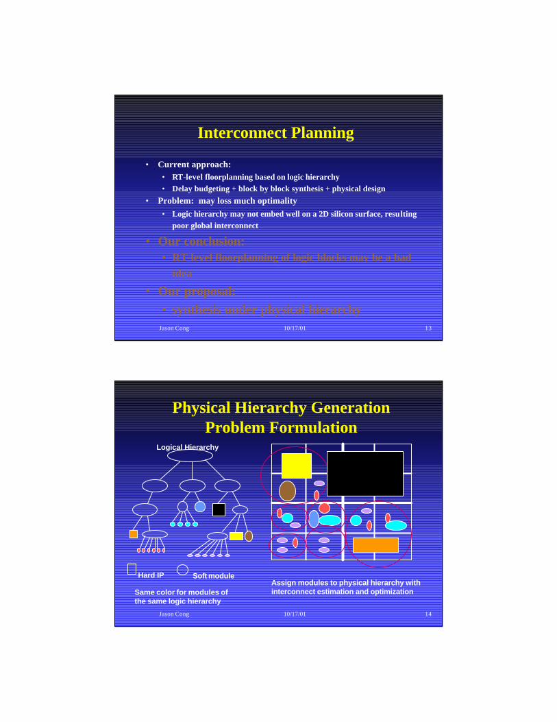
Interconnect Planning
• Current approach: • RT-level floorplanning based on logic hierarchy• Delay budgeting + block by block synthesis + physical design
• Problem: may loss much optimality• Logic hierarchy may not embed well on a 2D silicon surface, resulting
poor global interconnect
• Our conclusion: • RT-level floorplanning of logic blocks may be a bad
idea
• Our proposal:• synthesis under physical hierarchy
Jason Cong 10/17/01 14
Physical Hierarchy Generation Problem Formulation
Hard IP Soft module
Same color for modules of the same logic hierarchy
Logical Hierarchy
Assign modules to physical hierarchy with interconnect estimation and optimization
Jason Cong 10/17/01 15
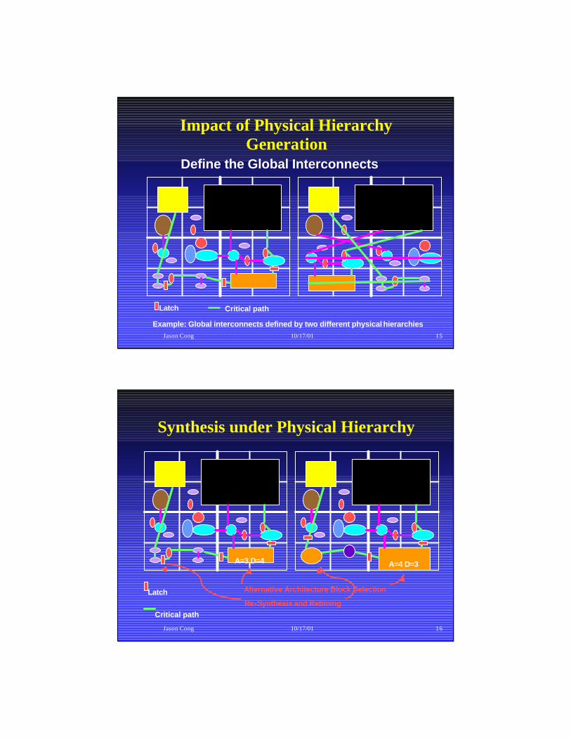
Impact of Physical Hierarchy Generation
Define the Global Interconnects
Example: Global interconnects defined by two different physical hierarchies
Critical pathLatch
Jason Cong 10/17/01 16
Synthesis under Physical Hierarchy
A=3 D=4 A=4 D=3
Latch Alternative Architecture Block Selection
Re-Synthesis and RetimingCritical path

Jason Cong 10/17/01 17
Difficulties in Physical Hierarchy Generation
? How to consider retiming/pipelining over global interconnects
? How to handle the high complexity of “almost flattened” designs
Use of the concepts of sequential arrival/required times
Use the multi-level optimization technique
Jason Cong 10/17/01 18
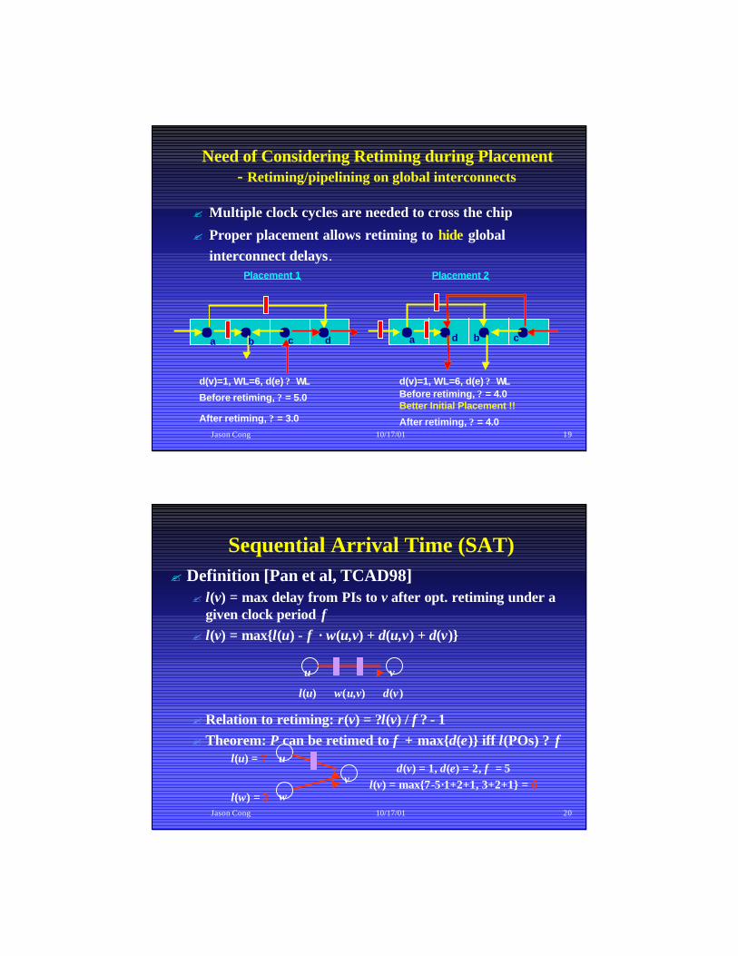
Need of Considering Retiming during Placement- Retiming/pipelining on global interconnects
? Multiple clock cycles are needed to cross the chip
? Proper placement allows retiming to hide global interconnect delays.
Placement 1
Before retiming, ? = 5.0
a b c d
After retiming, ? = 3.0
Before retiming, ? = 4.0
a cbd
Placement 2
d(v)=1, WL=6, d(e) ? WL d(v)=1, WL=6, d(e) ? WL
Better Initial Placement !!
Jason Cong 10/17/01 19
Need of Considering Retiming during Placement- Retiming/pipelining on global interconnects
? Multiple clock cycles are needed to cross the chip
? Proper placement allows retiming to hide global interconnect delays.
Placement 1
Before retiming, ? = 5.0
a b c d
After retiming, ? = 3.0
Before retiming, ? = 4.0
a cbd
After retiming, ? = 4.0
Placement 2
d(v)=1, WL=6, d(e) ? WL d(v)=1, WL=6, d(e) ? WL
Better Initial Placement !!
Jason Cong 10/17/01 20
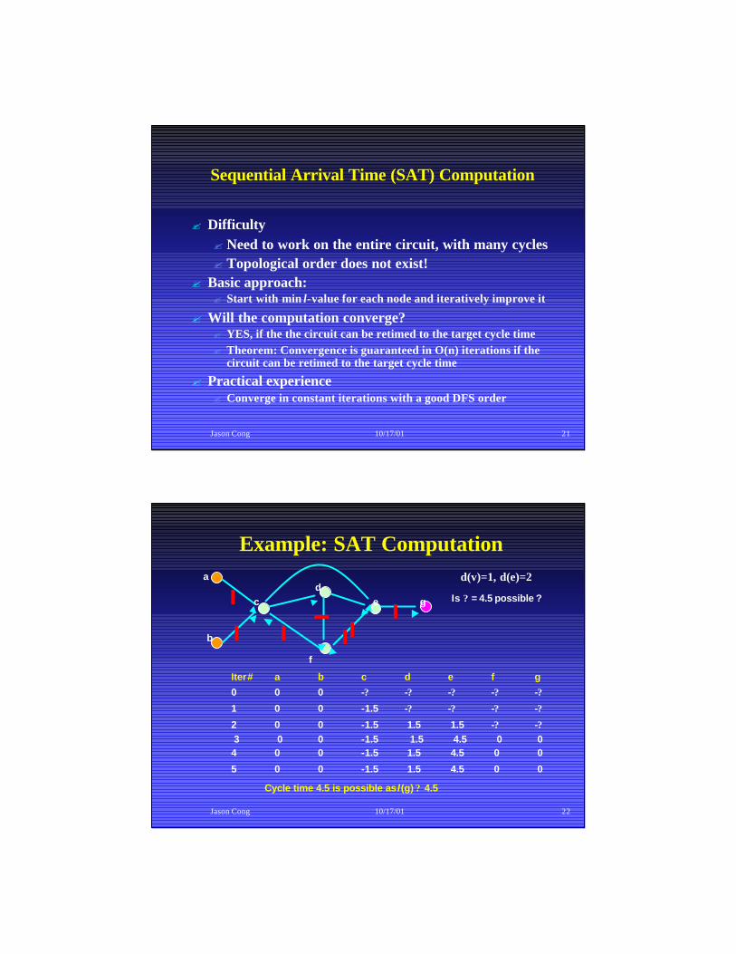
Sequential Arrival Time (SAT)? Definition [Pan et al, TCAD98]? l(v) = max delay from PIs to v after opt. retiming under a
given clock period f? l(v) = max{l(u) - f · w(u,v) + d(u,v) + d(v)}
? Relation to retiming: r(v) = ?l(v) / f ? - 1? Theorem: P can be retimed to f + max{d(e)} iff l(POs) ? f
u v
l(u) w(u,v) d(v)
u
wv
l(u) = 7
l(w) = 3
d(v) = 1, d(e) = 2, f = 5l(v) = max{7-5·1+2+1, 3+2+1} = 6
Jason Cong 10/17/01 21
Sequential Arrival Time (SAT) Computation
? Difficulty? Need to work on the entire circuit, with many cycles ? Topological order does not exist!
? Basic approach:? Start with min l-value for each node and iteratively improve it
? Will the computation converge?? YES, if the the circuit can be retimed to the target cycle time? Theorem: Convergence is guaranteed in O(n) iterations if the
circuit can be retimed to the target cycle time
? Practical experience? Converge in constant iterations with a good DFS order
Jason Cong 10/17/01 22
Example: SAT Computationd(v)=1, d(e)=2
Is ? = 4.5 possible ?
Iter# a b c d e f g
0 0 0 -? -? -? -? -?
1 0 0 -1.5 -? -? -? -?
2 0 0 -1.5 1.5 1.5 -? -?3 0 0 -1.5 1.5 4.5 0 04 0 0 -1.5 1.5 4.5 0 0
5 0 0 -1.5 1.5 4.5 0 0
Cycle time 4.5 is possible as l(g) ? 4.5
a
b
cd
e
f
g

Jason Cong 10/17/01 23
Example: SAT Computationd(v)=1, d(e)=2
Is ? = 4.5 possible ?
Iter# a b c d e f g
0 0 0 -? -? -? -? -?
1 0 0 -1.5 -? -? -? -?
2 0 0 -1.5 1.5 1.5 -? -?3 0 0 -1.5 1.5 4.5 0 04 0 0 -1.5 1.5 4.5 0 0
5 0 0 -1.5 1.5 4.5 0 0
Cycle time 4.5 is possible as l(g) ? 4.5
a
b
cd
e
f
g
Jason Cong 10/17/01 24
Simultaneous (Coarse) Placement with Retiming on Interconnects
?Our solution?Compute SATs of all nodes for a given
placement solution?Minimize SATs of POs by improving the
placement solution
?Alternative solution [Brayton, et al]?Enforcing all loop constraints during placement

Jason Cong 10/17/01 25
Difficulties in Physical Hierarchy Generation
? How to consider retiming/pipelining over global interconnects
? How to handle the high complexity of “almost flattened” designs
Use of the concepts of sequential arrival/required times
Use the multi-level optimization technique
Jason Cong 10/17/01 26
Multi-Level Framework
Coarsening Uncoarsening &Refinement (optimization)
Problem sizes
• Multi-level coarsening generates smaller problem sizes for top levels ? faster optimization on top levels
• Different levels explore different aspects of the solution space• Refinement on good solutions from coarser levels can be fast and
simple with good solution quality
Levels

Jason Cong 10/17/01 27
Successes of Multi-Level Approach
– First used to solve partial differential equations (multi-grid method)
– Successfully applied to circuit partitioning (hMetis[Karypis et al, 1997])– Best partitioner for cut-size minimization
– Successfully applied to physical hierarchy generation (HPM and GEO [Cong et al, DAC’00 & ICCAD’00])– 30-40% delay reduction compared to hMetis
– Successfully applied to circuit placement [Chan et al, ICCAD’00]– 10x speed-up over GordianL
Jason Cong 10/17/01 28
Physical Hierarchy Generation: Multi-Level Coarse Placement & Retiming
– Bottom-up multi-level clustering– Coarse placement at each level using multi-way
weighted min-cut or SA– Sequential timing analysis at each level
Timing analysis& cell move
Timing analysis& cell move
Next clusterlevel
Timing analysis& cell move
Next clusterlevel

Jason Cong 10/17/01 29
? Hierarchical approach: higher-level design constrains lower-level designs? Not sufficient information at higher-level? Mistake at higher level is impossible or costly to
correct
? Multi-level approach: finer-level design refines coarse-level design? Converge to better solution as more details are
considered
Hierarchical Approach vs. Multi-Level Approach
Jason Cong 10/17/01 30
Coarsening for Physical Hierarchy Generation (Multi-level Clustering)
? Follow logic hierarchy:? Connectivity based clustering:? hMetis [Karypis et al, DAC’97]
? Hyper-edge coarsening
? ESC [Cong and Lim, ICCAD’00]
? Global edge separability based clustering
? Performance driven multi-level clustering:? TLC [Cong and Romesis, DAC’01]
Jason Cong 10/17/01 31
D1
D2
D3
1st level cluster
2nd level cluster
1st level cluster
2nd level cluster
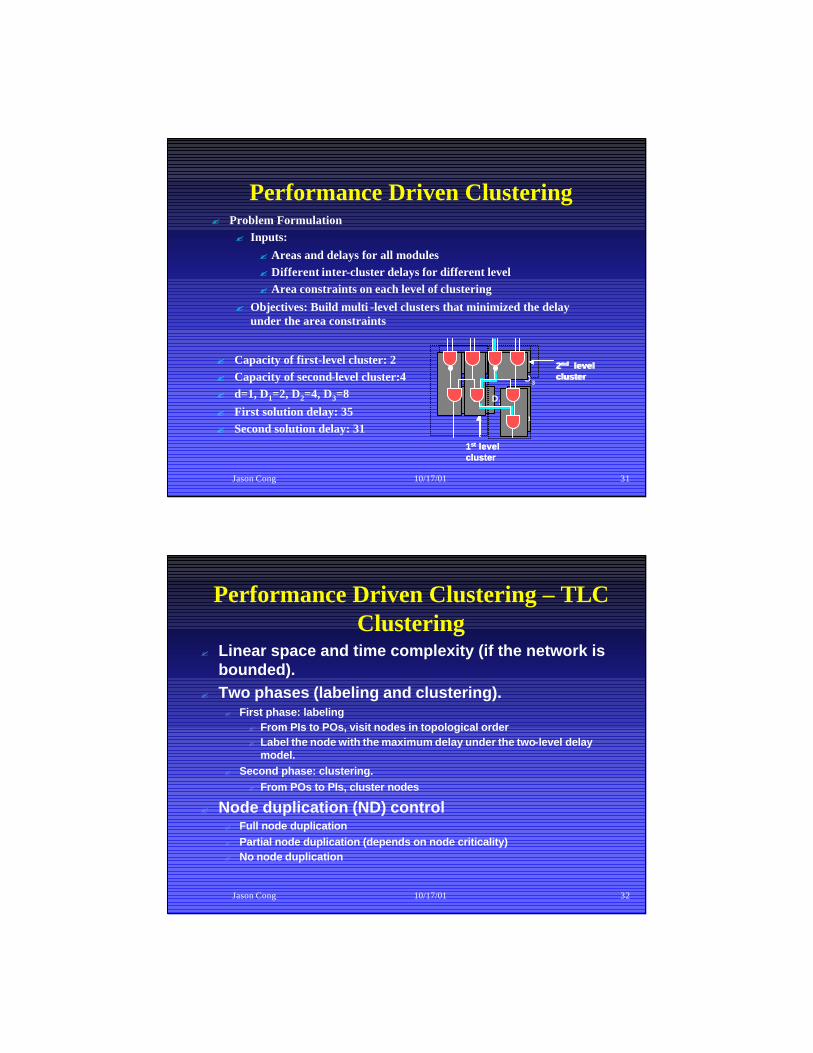
Performance Driven Clustering
? Capacity of first-level cluster: 2? Capacity of second-level cluster:4? d=1, D1=2, D2=4, D3=8? First solution delay: 35? Second solution delay: 31
? Problem Formulation? Inputs:
? Areas and delays for all modules ? Different inter-cluster delays for different level? Area constraints on each level of clustering
? Objectives: Build multi -level clusters that minimized the delay under the area constraints
Jason Cong 10/17/01 32
Performance Driven Clustering – TLC Clustering
? Linear space and time complexity (if the network is bounded).
? Two phases (labeling and clustering).? First phase: labeling
? From PIs to POs, visit nodes in topological order? Label the node with the maximum delay under the two-level delay
model.? Second phase: clustering.
? From POs to PIs, cluster nodes
? Node duplication (ND) control? Full node duplication ? Partial node duplication (depends on node criticality)? No node duplication

Jason Cong 10/17/01 33
TLC Experimental Results
0 20 40 60 80 100
Quartus
Quartus + TLC (noND)
Quartus + TLC (partialND)
Quartus + TLC (fullND)
Normalized Delay
For Altera APEX FPGAs with 2-level hierarchy (LABs & MegaLABs)
Jason Cong 10/17/01 34
Some Experimental Result• Comparison with existing algorithms
– hMetis [DAC97] + retiming + slicing floorplan [Algo89]– GEO: simultaneous partitioning + coarse placement + retimingClose to 40% delay reduction!
0
0.2
0.4
0.6
0.8
1
1.2
1.4
delay cutsize wire runtime
hMetis+RT+FLGEO

Jason Cong 10/17/01 35
Experiment on an IBM Design
Physical Hierarchy Generation Detailed Placement by IBM tools
270k cells, 300k nets Technology: ibm_sa27e (0.11um copper)
Jason Cong 10/17/01 36
Interconnect-Centric IC Design Flow Under Development at UCLA
Architecture/Conceptual-level Design
Design Specification
Final Layout
abstractionStructure viewFunctional viewPhysical viewTiming view
HDM
Synthesis and Placement under Physical Hierarchy
Interconnect Planning•Physical Hierarchy Generation•Foorplan/Coarse Placement with Interconnect Planning•Interconnect Architecture Planning
Interconnect Optimization(TRIO)
• Topology Optimization with Buffer Insertion• Wire sizing and spacing• Simultaneous Buffer Insertion and Wire Sizing• Simultaneous Topology Construction
with Buffer Insertion and Wire Sizing
Interconnect LayoutRoute Planning
Point-to-Point Gridless Routing
Interconnect PerformanceEstimation Models (IPEM)
•OWS, SDWS, BISWS
Interconnect SynthesisTopology genration & wiresizng for delay
Wire ordering & spacing for noise control
Jason Cong 10/17/01 37
Ongoing Work – Synthesis under Physical Hierarchy
? Consider interconnect information during behavior and logic level synthesis? Explore various synthesis solutions to tradeoff long
global wires with short local wires? Select different behavior and logic synthesis
solutions for each block for global optimization? Scheduling for hiding interconnect latency ? ……
Jason Cong 10/17/01 38
Ongoing work – Micro-architecture Evaluation
? Architecture blocks with different implementations with? Different areas? Different delays? Different pipeline stages? …
? Parameterized Buses with different bus widths? Interconnect planning extracts area, delay, etc. for
architecture evaluation? Interconnect planning uses architecture evaluation
functions to explore alternative architecture blocks and buses for system performance optimization
Jason Cong 10/17/01 39
Concluding Remarks? Interconnects determine system performance? An interconnect-centric design flow is needed
? Interconnect planning? Synthesis/layout under physical hierarchy? Interconnect synthesis
? Interconnect layout
? Physical hierarchy generation is crucial for interconnect planning
? A good combination of partitioning/placement and retiming can hide global interconnect delays, and lead to good physical hierarchy
? Multi-level method is an effective way to cope with complexity
Jason Cong 10/17/01 40
Acknowledgements
? Thanks for current and former students contributed to this project: Chin-Chih Chang, Ashok Jagannathan, Sung Lim, David Pan,Michail Romesis, Chang Wu, and Xin Yuan
? Thanks supports from GSRC, SRC, Fujitsu, IBM, and Intel
More details: http://cadlab.cs.ucla.eduhttp://cadlab.cs.ucla.edu