analog arc-1 release controller - fireflex · doc. no fm-072z-0-01 rev. h march 2010 systems inc...
TRANSCRIPT

Doc. No FM-072Z-0-01 Rev. H March 2010
Systems Inc
ANALOG RELEASE
CONTROLLER
INSTALLATION AND OPERATION MANUAL
ARC-1® Analog Release Controller
Acknowledge
Alarm Silence/ Activate
SystemResetGround Fault Discharge
AC Power
AudiblesSilence Release
PartialDisable
Trouble
Supervisory
Alarm
ARC-1
TABLE OF CONTENT ARC-1 ANALOG RELEASING CONTROLLER
- ii - FM-072Z-0-1H
FIREFLEX Systems Inc. 1935 Lionel-Bertrand Blvd
Boisbriand, QC (Canada) J7H 1N8 Tel: (450) 437-3473 Toll free: (866) 347-3353
Fax: (450) 437-1930 Web Site: http://www.fireflex.com - E-Mail: [email protected]

TABLE OF CONTENT ARC-1 ANALOG RELEASING CONTROLLER
FM-072Z-0-1H - iii -
Description Page No.
Section 1 - General Description .................................................................................................................................1 1. NFPA Standards....................................................................................................................................................................1 2. Additional Information ............................................................................................................................................................1 3. Listings & Approvals ..............................................................................................................................................................1
Panel Features ...............................................................................................................................................................................1 Special features..............................................................................................................................................................................1
1. Pressure transducers.............................................................................................................................................................2 2. Air compressor control ...........................................................................................................................................................2 3. Automatic emergency batteries test.......................................................................................................................................2
Panel Modules................................................................................................................................................................................2 1. Standard Modules..................................................................................................................................................................2 2. Optional Modules...................................................................................................................................................................2
Specifications .................................................................................................................................................................................2 Section 2 - Modules Description & Wiring ................................................................................................................5
1. PSA Power Supply Module....................................................................................................................................................5 2. BCA Battery Charger Module ................................................................................................................................................5 3. MBA Motherboard..................................................................................................................................................................5 4. SCA System Control Module .................................................................................................................................................6 5. GIA Galvanic Isolation Module...............................................................................................................................................6 6. SSA System Supervisory Module ..........................................................................................................................................6 7. ARA Auxiliary Relay Module ..................................................................................................................................................7 8. SOA Supervised Output Circuit Module.................................................................................................................................7 9. SIA Initiating Circuit Module...................................................................................................................................................8 10. TIA Transducer Input Module ..............................................................................................................................................8 11. LAA Local Alphanumeric Annunciator .................................................................................................................................9 12. CCA Communication Converter Module ..............................................................................................................................9 13: TBA Power Input Terminal...................................................................................................................................................9
Section 3 - User Interface .........................................................................................................................................11 1. System Status Lamps..........................................................................................................................................................11 2. Keyboard - System Main Control Keys ................................................................................................................................12 3. Keyboard - Menu Navigation Keys ......................................................................................................................................12 4. Keyboard - User Defined Keys ............................................................................................................................................13 5. Local Alphanumeric Display.................................................................................................................................................14
User Menus...............................................................................................................................................................15 1. System Data Level...............................................................................................................................................................16
1.1 Events Log .....................................................................................................................................................................16 1.2 System Information ........................................................................................................................................................17
2. Basic Setup Level ................................................................................................................................................................17 2.1 Change Password..........................................................................................................................................................17 2.2 Date / Time.....................................................................................................................................................................18 2.3 Disable Utility .................................................................................................................................................................19 2.4 Battery Capacity.............................................................................................................................................................20
3. Technical Setup ...................................................................................................................................................................20 3.1 Parameters.....................................................................................................................................................................20 3.2 Timers / Counters...........................................................................................................................................................22 3.3 User Description.............................................................................................................................................................22 3.4 Crossed Zones...............................................................................................................................................................23 3.5 Circuit Configuration.......................................................................................................................................................23 3.6 Solenoid Configuration...................................................................................................................................................25 3.7 Sensors Configuration....................................................................................................................................................25
TABLE OF CONTENT ARC-1 ANALOG RELEASING CONTROLLER
- iv - FM-072Z-0-1H
4. Advanced Setup Level (Factory) ........................................................................................................................................ 27 4.1 Parameters .................................................................................................................................................................... 27 4.2 Clear Events Log ........................................................................................................................................................... 28 4.3 Sensors Calibration........................................................................................................................................................ 28 4.4 System Configuration..................................................................................................................................................... 29 4.5 Configuration of F1, F2, F3 ............................................................................................................................................ 31
Section 4 - Factory Programming ............................................................................................................................33 Programming principles............................................................................................................................................................ 33 1. Detection Conditions Block.................................................................................................................................................. 33 2. Pre-discharge Conditions Block........................................................................................................................................... 34 3. Release Conditions Block.................................................................................................................................................... 35 4. Discharge Modes Block....................................................................................................................................................... 35 5. Special functions ................................................................................................................................................................. 37 6. Operation Modes Rules....................................................................................................................................................... 37
Appendix A – Compatible Devices ..........................................................................................................................39 Appendix B – Emergency Batteries Sizing .............................................................................................................44 Appendix C – Cabinet Details / Wiring Routing......................................................................................................45 Appendix D - Troubleshooting .................................................................................................................................47
Normal Conditions .................................................................................................................................................................... 47 Abnormal Conditions ................................................................................................................................................................ 47 Circuit I.D. Codes ..................................................................................................................................................................... 48 Internal Events ID Codes.......................................................................................................................................................... 50 Events Type Codes .................................................................................................................................................................. 52
Limited Warranty .......................................................................................................................................................54

TABLE OF CONTENT ARC-1 ANALOG RELEASING CONTROLLER
FM-072Z-0-1H - v -

TABLE OF CONTENT ARC-1 ANALOG RELEASING CONTROLLER
- vi - FM-072Z-0-1H
Copyright © 2004-2012 FIREFLEX Systems Inc.
All Rights Reserved Reproduction or use, without express written permission from FireFlex Systems Inc, of any portion of this manual is prohibited. While reasonable efforts have been taken in the preparation of this manual to assure its accuracy, FireFlex Systems Inc assumes no liability resulting from any errors or omissions in this manual, or from the use of the information contained herein.
FireFlex Systems Inc. reserves the right to make changes to this manual at any time, without prior notification.
SECTION 1 GENERAL DESCRIPTION ARC-1 ANALOG RELEASING CONTROLLER
FM-072Z-0-1H - 1 -
Section 1 - General Description
The ARC-1 control panel is an Analog Releasing Controller, intended to be used as the releasing panel of fire extinguishing systems. This controller will generally be integrated with FireFlex Systems' family of Integrated Fire Protection Systems (such as the TotalPac2 integrated Systems or the new ICAF Integrated Compressed Air Foam fire extinguishing systems). Alternately, this controller can also be used independently with non-integrated type systems to control the release of supervised gaseous or water mist type fire extinguishing systems. The ARC-1 Analog Releasing Controller is a microprocessor based dynamic control system specifically designed for fire protection systems release. The system is modular in design and consists of power supply modules, battery charger, general control board, set of contractor wiring terminals modules, emergency batteries and a door mounted local alphanumeric annunciator. All the equipment is included in a sturdy gauge 14 steel cabinet painted fire red. The system's detection zones are intended to be used with either compatible conventional type smoke detectors (refer to the detector compatibility chart provided with this manual) or any listed dry contact type detection device. The control panel is resistant to electromagnetic interference and has been designed and tested to meet stringent EMI shielding requirements. The panel architecture is designed for future expansion and is based on a standard 19" rack configuration with slide-in cards.
1. NFPA Standards The ARC-1 panel complies with the following standards:
NFPA-11 Standard for Low, Medium and High-Expansion Foam; NFPA-13 Sprinkler Systems; NFPA-15 Water Spray Systems; NFPA-16 Foam-Water Deluge and Foam-Water Spray Systems; NFPA-72 Local (Automatic, Manual and Water flow) Fire Alarm Systems.
2. Additional Information Before the installation, the contractor installing the panel should be familiar with all applicable documents and standards and the requirements of the Local Authority Having Jurisdiction (AHJ). Also refer to the list of compatible devices provided with this manual.
3. Listings & Approvals The ARC-1 Release Control Panel is c-FM-us Approved by Factory Mutual <FM> as a Fire Alarm Control for Automatic Release of Extinguishing Systems, and is certified for use in the USA and Canada. The ARC-1 Release Control Panel is also CFSM listed for use in California.
Panel Features
- Slot Cards configuration on standard 19" rack (5U) installed in steel cabinet measuring 36" x 20" x 16" (91,4 x 50,8 x 40,6 cm) or 46" x 24" x 16" (116,8 x 61 x 40,6 cm) depending on the configuration.
- Standard input / output layout: - 2 Style B/D initiating device circuits - 2 Style B dry contacts supervisory circuits - 3 pressure transducer circuits - 3 Style Y/Z notification appliance circuits (signalling or
releasing mode) - 4 User-definable auxiliary relays. - Additional space for 5 plug-in I/O cards. - Microprocessor based 'Plug & Play' distributed
architecture. - Watchdog supervised microprocessor. - Power limited on all circuits. - All output circuits protected against false activation. - Dynamic over current protection on all notification
appliance circuits. - Alarm and trouble subsequent signal (resound). - Local RS-232 Serial Communication Output for
technician's PC interface. - Remote RS-485 Serial Communication Output for remote
PC interface. - Dynamic integrated digital battery Volt./Amp. meter. - Local alphanumeric annunciator with up to 16 lines of 40
characters. - 24Vdc power regulated output, up to 7.5A - Standard 26Ah batteries for 24 hours standby, with 104Ah
option for up to 90 hours standby. - Automatic battery test feature. - Resettable and non-resettable regulated power outputs. - Extensive transient protection on all circuits. - Last events recall with up to 500 events in memory. - 3 levels of password protected user menus. - User-definable standard timers (4) and counters (4) for
time-in, time-out, soak timer, etc. - Slide-in identification labels for easy custom identification
of user defined keys.
Special features
Many special features have been integrated in the system's design to enhance its level of system integrity supervision for the various fire protection applications. One of the most interesting features of the ARC-1 is the fact that although the system is factory programmed, it still allows the user to define input zones and / or output circuits without any consequence on the system's initial programming, making retrofits and site modifications very safe. Other special features include the following:

GENERAL DESCRIPTION SECTION 1
ARC-1 ANALOG RELEASING CONTROLLER
- 2 - FM-072Z-0-1H
1. Pressure transducers This system has been designed to operate with factory installed pressure transducers. Those pressure transducers can be used to dynamically supervise fire protection systems water or air pressures and improve the level of supervision for the system's integrity. Up to 6 pressure transducers can be connected to the ARC-1 control panel. All wires connecting the transducers are electrically supervised against opens or short circuits. Different set points can be defined per transducer, able to generate low and high pressure supervisory status. For example, one point can be set at 20 psi for low air pressure supervisory while another point is set at 40 psi for high air pressure supervisory on the same transducer. Pressure information from the transducers is available at the alphanumeric display and can also be transmitted remotely via the RS-485 communication port.
2. Air compressor control Pressure transducer no. 1 can be used to control the start and stop function of the air compressor often provided with integrated preaction systems. In such applications, normal and differential pressures are factory set to meet the specific needs of the configuration used (ie: single or double interlocked).
3. Automatic emergency batteries test The ARC-1 control panel is configured so that once every 30 days, system power is automatically transferred to the batteries in order to perform a good verification of their backup capacity. Batteries sometimes will indicate a normal voltage reading when a float current is applied to them but will actually show a substantial voltage drop when the AC power is lost and an actual load is applied. Before performing the battery test, the system will save their voltage reading in memory and will then transfer power to the batteries for a pre-determined period of time. At the end of this test period the system will compare the actual batteries voltage reading to the one in memory and if an important voltage drop is registered, will generate a trouble condition. At all times during the test, should the batteries voltage drop below a specific voltage value, power will be transferred back to the AC source and system will generate a trouble condition.
Panel Modules
1. Standard Modules - Motherboard, Model MBA: Provides the system main
bus and card cage with slots to receive all the standard system plug-in modules.
- Power Supply, Model PSA: Provides up to 7.5A of filtered 24Vdc and switched output for optional power relay and air compressor control.
- Battery Charger, Model BCA: Provides charging power for emergency batteries at 26, 78 or 104Ah with brownout detection circuitry.
- Control Module, Model SCA: Controls general communication and performs required commands
between the various components of the panel. Also provides internal serial communication port (RJ45) for PC control via RS-232 and local alphanumeric display.
- Transducer Interface Module, Model TIA: Provides the interface circuitry for 3 pressure transducers, giving dynamic supervision of both air and water pressures.
- Galvanic Isolation Module, Model GIA: Provides the opto data isolation circuitry against electromagnetic interference and ground fault detection.
- System Supervisory Module, Model SSA: Provides the supervisory and supply circuitry with resettable and non-resettable 24Vdc power outputs, plus one set of trouble operated Form C dry contacts and one RS-485 serial communication output for remote equipment.
- Supervised Inputs Module, Model SIA: Provides 2 user-definable detection zones and 2 linear impedance supervisory zones.
- Supervised Outputs Module, Model SOA: Provides 3 user-definable output circuits with FireFlex' exclusive coil-sense circuitry.
- Auxiliary Relay Module, Model ARA: Provides 4 SPDT user-definable relays for auxiliary functions.
- Local Alphanumeric Display, model LAA: Back-lit alphanumeric display with 16 lines of 40 characters mounted on the front door of the unit. Provides user-friendly textual indications of all system status and various user menus plus a control and navigation membrane type keyboard.
2. Optional Modules - Data Communication Converter Module, Model CCA:
Connected to the RS-485 external serial output of the SSA System Supervisory Module, converts the serial output from RS-485 to RS-232 for remote PC connection. Provides indication and control directly from a Windows™ based Personal Computer. Dedicated software provides many useful features such as live system air data logging, events history, and dynamic batteries supervision. All reports can also be printed for archival purposes.
- Factory Wired Supplementary Module, Model TBB: Provides wiring terminals for linear impedance, factory wired release system supervisory devices.
Specifications
AC Power: Panel requires a supply of 2.8A - 120Vac at 60 Hz (1.4A - 220Vac at 50/60Hz) from an independent branch circuit breaker, lockable and identified for its purpose. Minimum wire size: 14 AWG with 600V insulation.
Batteries (lead acid only): Maximum charging circuit: 4A Maximum battery capacity: 104Ah Standard batteries provided with the unit are two 12Vdc 26Ah, providing 5 minutes of alarm after 24 hours of standby, as per UL & ULC requirements. 104Ah batteries are also available for a standby period of up to 90 hours meeting Factory Mutual (FM) requirements.
Initiating Device Input zones (2 per SIA module):
SECTION 1 GENERAL DESCRIPTION ARC-1 ANALOG RELEASING CONTROLLER
FM-072Z-0-1H - 3 -
Dynamic power limited circuitry Operation: Class B (Style B) / Class A (Style D) Nominal operating voltage: 21Vdc Alarm current: 15mA minimum Short circuit current: 50mA maximum Maximum detector current in standby: 3mA (max) per zone Maximum loop resistance: 200 ohms End-of-line resistor: 4.3K - ¼W (3.6K for ProtectoWire detection) Reset time: 10 seconds maximum Each heat/smoke detectors and/or manual pull station detection zone is supervised against shorts, grounds and cross-zone operation and for normally open or closed detection devices. Refer to APPENDIX A for the list of compatible devices.
4-Wire Smoke Detector Power (on SSA module): Up to 100mA resettable power is available for powering 4-wire type smoke detectors. Maximum ripple voltage: 100mV p/p. Refer to APPENDIX A for the list of compatible devices.
Linear Impedance Supervisory zones (2 per SIA module): Dynamic power limited circuitry Operation: Class B (Style B) only Max. Operating Voltage: 4.5Vdc Open loop voltage: 12Vdc Supervisory current: 1mA Maximum loop resistance: 39 Ohms Max. End-of-line resistor: 4.3K - ¼W. except when TBB module Is used.
Each zone is supervised against grounds and opens. Normally open contact devices such as pressure, tamper or flow switches are used on these zones to supervise the extinguishing system status. They are factory wired to the TBB Module or wired on-site by the user when not factory wired.
Transducer Interface Circuit (3 per TIA module): Bridge Voltage: 5.0V Nominal. Differential Input Voltage: 0 – 100mV. This circuit is used for FireFlex exclusive sprinkler Digital Pressure Sensor, DPS Series and supervises the system air and / or water pressure and control the air compressor when one is provided.
Notification Appliance and Releasing Circuits (3 per SOA module): Dynamic power limited circuitry. Maximum allowable voltage drop due to wiring: 2Vdc Nominal operating Voltage: 24Vdc Total current available to all external devices: 6.0A Maximum signalling current per circuit: Up to 3A per module or 1.5A per circuit. End-of-line resistor: 4.3K - ¼W. except with solenoids. Refer to the list of compatible devices.
Auxiliary Relays (4 per ARA module): User-definable Dry Form-C contacts rated at 30V, 3A N.O., 1A N.C. All relays must be connected to a power limited circuit.
Non-resettable Power Circuit:
Nominal operating Voltage: 24Vdc. Provides up to 1.5A of power available for external devices (subtract from the allowable 6A).
Resettable Power Circuit: Nominal operating Voltage: 24Vdc Total current: up to 100mA Reset time: 10 seconds maximum.
External RS-485 Serial Communication Loop: Maximum distance to remote equipment: 4000 ft. Bit rate: 19,200 bauds.
Local RS-232 Serial Communication Loop: Maximum allowable distance: 25 ft. Bit rate: 19,200 bauds Used for servicing the system through P3 connector on SCA Module with local computer (using an RJ-45 cable with an RJ-45 to DB-9 adapter).
Contractor Wiring: Many of the modules provide easily accessed front mounted sturdy screw type connectors for contractor field wiring, with every terminal identified directly on the front plate of the module itself. Maximum wire size: 14AWG.
Note: For EMC Compliant systems, wiring must be shielded type, with the shield mechanically connected to the grounding bar and installed with EMC compliant devices.
GENERAL DESCRIPTION SECTION 1
ARC-1 ANALOG RELEASING CONTROLLER
- 4 - FM-072Z-0-1H
Front view with panel door closed:
Control section hinged door(recessed hinges on the top)
Releasing panel controlsaccess door (stainless steel)
Control panelannunciator window
Door locks(key-alike)
Flush door handle
ARC-1®Analog Release Controller
Front view with panel door open:
65
8
9
7
4321
56
1112
101112
8
109
7
56
2
43
1
8
943
721
8
9
7
4321
1211
65
1211
561112
10 1010
1
34
2FM
-072
C-0
-246
D.d
wg
AC Power Supply Terminals
System Control Modules
Air Compressor Cut-Out Switch and Contactor Ass'y (when provided)
Emergency Batteries
8
9
7
TIA SCA GIA SSA SIA SOA ARA
Y
R
Y
R
Power Supply & Battery Charger Modules
Input / Output Modules
Transducers Modules
ON
OFF
TBB Module (factory wired)Grounding Bar
N.U. N.U. N.U. N.U. N.U.
Optional Input / Output Modules
BlankPSA
BCA
TBA
TBB TBB (optional)
Blank Blank Blank Blank1 2 A B C 3 4 5 6 7 8 9
SECTION 2 MODULES DESCRIPTION & WIRING ARC-1 ANALOG RELEASING CONTROLLER
FM-072Z-0-1H - 5 -
Section 2 - Modules Description & Wiring
1. PSA Power Supply Module The PSA Power Supply Module is installed directly inside the ARC-1 Enclosure, near the TBA wiring terminal to which it is factory wired. The module contains all the circuitry necessary for powering the system and connects directly with the BCA Battery Charger Module (see description below) to provide regulated system power (up to 7.5A of current at 24Vdc) along with extensive EMI protection circuitry. System fuses (F1, F2 & F3) are located on the front of the module for ease of servicing (see detail below). F1 and F2 protect the PSA module against high surge transients on the AC supply, F3 protects the unit against shorts on the external components wiring.
Detail of PSA Module:
1 2 3 4 5 6
F3 F2 F12A 5A 5A SLOW BLOW
PSA
P1
Factory connectedharness to BCA Module
Factory wired harnessto TBA Terminal
& internal components
Power Fuses
2. BCA Battery Charger Module The BCA Battery Charger Module is installed directly next to the PSA Module and provides battery charging capability for the system. The module can charge 24Vdc batteries rated at 26, 78 or 104Ah (user selectable through both the SW1 selector switch on the circuit board itself and with the user menu). SW1 Switch must be adjusted as per battery capacity provided with the system. Refer to APPENDIX B for battery sizing calculations.
The module also automatically transfers power to emergency batteries from the PSA Module when AC power is lost or falls below 85% of its nominal value (120 or 220Vac). F1 fuse protects the BCA module against battery connection shorts or polarity reversal. Control signals are exchanged internally with the SCA Module for features such as battery test, power switching on AC and emergency batteries, etc.
Detail of BCA Module:
SW1
P4 - Factory connectedflat cable to SCA Module
P2 - Factory connectedharness to GIA Module
P1 - Factory connectedharness to PSA Module
SW1 BatterySelection Switch
Battery Fuse10A
F110A
BCA
P1 P2 P3 P4
P3 harness to Batteries
3. MBA Motherboard The MBA Motherboard is mounted at the back of the card cage holding all the control and slide-in modules of the system. It is designed to accept the various system slide-in modules and provides the system main bus to which all modules are connected. The MBA Motherboard is built as to be compatible with 19" rack mounting and uses a standard '5U' height space. It has connecting slots for 12 slide-in modules which are protected against wrong slot insertion. Field wiring terminals are provided at the front of the various modules. Note: When laying down field wiring, care should be taken to
route the wires so removal of slide-in modules is not hampered by the wiring.
Refer to APPENDIX C, Wiring Routing detail for more information.
MODULES DESCRIPTION & WIRING SECTION 2
ARC-1 ANALOG RELEASING CONTROLLER
- 6 - FM-072Z-0-1H
MBA Motherboard Detail : (with Basic Configuration Slide-In Modules shown in their default location)
SCA GIA SSA ARASIA SOA
Transducer Interface (Slots # 1 & 2) System Control (Slot # A)
Galvanic Isolation (Slot # B) System Supervisory (Slot # C)
Supervised Input Zones (Slot # 3) Supervised Output Circuits (Slot # 4)
Aux. Relay Outputs (Slot # 5) I / O Slide-In Modules Placement (ARA, SIA or SOA - Slots # 6 to 9)
EXT/ALM
P1
8
56
43
10
1211
9
1
27 7
1
2
61112N.U.
410
5
9
83
71
BlankTIA Blank Blank BlankBlank1 2 A B C 3 4 5 6 7 8 9
INT/TBL
P3
P2
N.U.
2
N.U.
6
4
5
3
1112
109
8
17
2
116
12N.U.
410
5
39
87
1
28
910
N.U.1211
6
4
5
3
4. SCA System Control Module The SCA System Control Module is mounted in Slot #A of the MBA Motherboard. It offers the following features:
- Dual microprocessor based. - Watchdog circuitry. - Flash memory (for Event Recall library and system's
configuration parameters). - 4 system status lamps: Alarm, Trouble, Internal &
External Data Communication. - Connected to the GIA Module via front mounted flat
cable (P1). - Interface with the LAA Local Annunciator Module with flat cable P2. - RS-232 Port for connection to local PC Interface (P3) with RJ45 connector. - Connectors are supervised and system will go on trouble
condition if disconnected while system is powered.
5. GIA Galvanic Isolation Module The GIA Galvanic Isolation Module is mounted in Slot #B of the MBA Motherboard. It handles the required isolation between the system's two grounds (chassis ground and system ground – 0V) in order to manage the EMI protection of the system.
6. SSA System Supervisory Module The SSA System Supervisory Module is mounted in Slot #C of the MBA Motherboard. It provides the following circuitry:
- Common Trouble Relay, Form C contacts rated at 30V 1A DC / 0.5A AC. This contact is watchdog supervised and provides closure for any kind of troubles in the system. - RS-485 Serial Port connection and required power source for connection to RS-485 based devices. - Non-resettable 24Vdc Power Supply (1.5A). - Resettable 24Vdc Power Supply (100mA).
The 100mA power source provides power for 4-Wire type smoke detectors. Refer to the Input Zones Wiring Diagram (SIA Module) and APPENDIX A, Table 3 for the device compatibility chart. Calculation of the maximum allowable resistance in the 24Vdc detector power wiring is done using the following formula:
RMAX = ( )( ) ( ) IrIaNaIsN
Vom
+×+×
×− 10004.20
SECTION 2 MODULES DESCRIPTION & WIRING ARC-1 ANALOG RELEASING CONTROLLER
FM-072Z-0-1H - 7 -
Where: RMAX is the maximum resistance of the 24V wires, in Ohms. Vom is the minimum operating voltage of the detector or end-of-line relay, whichever is greater, in volts.
N is the total number of detectors on the 24V supply loop.
IS is the detector current in standby (mA). NA is the number of detectors on the 24V power loop
which must function at the same time in alarm. IA is the detector current in alarm (mA). IR is the end-of-line relay current (mA).
To calculate the maximum quantity of smoke detectors allowable per system, use the following formula:
DMAX = ( )Is
IrmA −100
Where: DMAX is the maximum number of 4-wire type smoke
detectors IR is the end-of-line relay current (mA). IS is the detector current in standby (mA).
SSA Module wiring detail:
N.U.
V+
V -
A
B
NC
NO
C
COMMON TROUBLE RELAYRATED 30V, 3A N.O. / 1A N.C.
RESETTABLE POWERSUPPLY - 24VDC, 100mA
POWER SUPPLY - 24VDC, 1.5ANON-RESETTABLE
PORT CONNECTION
N.U.
24V / V -
24V / V+
24VR / V -
24VR / V+
SSA
RS485 SERIAL
1
2
3
4
7
10
9
8
6
5
12
11
7. ARA Auxiliary Relay Module This module provides 4 DPST auxiliary relays that can be assigned for Alarm, Trouble, Supervisory, Water Flow, etc., for use with power-limited circuits only. The ARA Auxiliary Relay Module is mounted on Slot #5 of the MBA Motherboard. Additional slide-in modules can also be mounted on Slots #6 to #9. Relays activation can be user-defined. Refer to USER MENUS for the list of available functions and configurations.
ARA Module wiring detail:
N.U.
K1
CONTACTS RATED 30V, 3A N.O. / 1A N.C.
K3
K2K4
C
N.O.
N.C.
N.C.
C
N.O.
N.C.
C
N.O.
N.C.
C
N.O.
ARA
1
2
3
4
7
10
9
8
6
5
12
11
8. SOA Supervised Output Circuit Module The SOA Supervised Output Circuit Module provides 3 circuits for signaling or releasing devices, circuit #1 being a releasing circuit by default. It is mounted on Slot #4 of the MBA Motherboard. Additional slide-in modules can also be mounted on Slots #6 to #9. Circuits can be user-defined. Refer to USER MENUS for the list of available functions and configurations. Standard configuration circuits include:
- Class B (Style Z) releasing circuits with dynamic coil supervision circuitry, providing trouble condition if coil is physically separated from the solenoid body; - Class A or B (Style Z or Y) signaling circuits; - Dynamic current limiting circuitry.
SOA Module typical wiring detail:
SOA
EOLSIGNALLING
TYPICAL CLASS 'B' / STYLE 'Z' CIRCUITS
EO
L
CIRCUIT S2
24VDC LISTED RELEASING DEVICE
RELEASING CIRCUIT S11
2
3
4
7
10
9
8
6
5
12
11E.O.L.4.3K
1/4W
1/4W4.3K
E.O.L.
N.U.
S
SIGNALLINGCIRCUIT S3
B+
B -
B -
B+
B -
B+
-
+
-
+
-
+
-
+
-
+
-
+
TYPICAL CLASS 'A' / STYLE 'Y' CIRCUITS
8/10/12
7/9/111/3/5
2/4/6
SIGNALLINGCIRCUIT (TYP.)
B -
B+A+
A -
S1, S2 or S3 -
+
-
+
-
+
Each circuit is rated 24VDC, 1.5A, 3A max. per SOA Module (substract from the allowable 6A).
NOTE: Observe polarity when connecting polarized devices. Polarity is reversed in normal supervisory condition.
MODULES DESCRIPTION & WIRING SECTION 2
ARC-1 ANALOG RELEASING CONTROLLER
- 8 - FM-072Z-0-1H
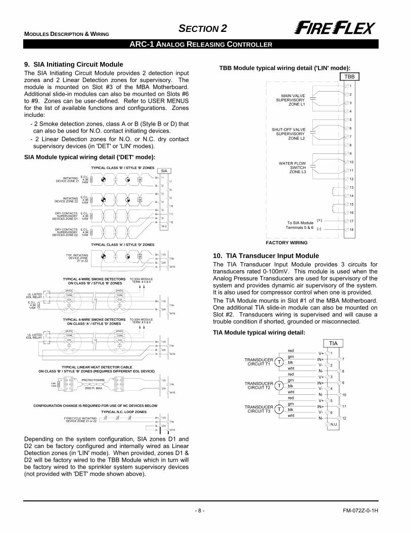
9. SIA Initiating Circuit Module The SIA Initiating Circuit Module provides 2 detection input zones and 2 Linear Detection zones for supervisory. The module is mounted on Slot #3 of the MBA Motherboard. Additional slide-in modules can also be mounted on Slots #6 to #9. Zones can be user-defined. Refer to USER MENUS for the list of available functions and configurations. Zones include:
- 2 Smoke detection zones, class A or B (Style B or D) that can also be used for N.O. contact initiating devices.
- 2 Linear Detection zones for N.O. or N.C. dry contact supervisory devices (in 'DET' or 'LIN' modes).
SIA Module typical wiring detail ('DET' mode):
1
2
3
4
7
10
9
8
6
5
12
11
8/10
7/91/3
2/4
DEVICES ZONE D1
DEVICES ZONE D2
DRY CONTACTSSUPERVISORY 4.3K
E.O.L.
1/4W
1/4W4.3K
E.O.L.
E.O.L.4.3K
1/4W
1/4W4.3K
E.O.L.
TYPICAL N.C. LOOP ZONES
FYRECYCLE INITIATINGDEVICE ZONE Z1 or Z2
8/10
7/91/3
2/4
7/9
8/10
1/3
2/4
EO
L
ON CLASS 'B' / STYLE 'B' ZONESTYPICAL 4-WIRE SMOKE DETECTORS
UL LISTEDEOL RELAY
4.3KE.O.L.
1/4W
TO SSA MODULETERM. # 5 & 6
ON CLASS 'A' / STYLE 'D' ZONES
UL LISTEDEOL RELAY
7/9
8/102/4
TERM. # 5 & 6TO SSA MODULE
1/3
24VDC
COM
CDI
24VDC
COM
CDI
24VDC
COM
CDI
24VDC
COM
CDI
N.U.
INITIATINGDEVICE ZONE Z2
TYP. INITIATINGDEVICE ZONE
M
M
M
B+
B-
B-
B+
B-
B+
B-
B+
A-
A+B-
B+
B-A-
A+B+
B+
B-
B-A-
B+A+
Z1 or Z2
TYPICAL 4-WIRE SMOKE DETECTORS
PROTECTOWIRE
EOL
-
+
-
+
-
+3.6K1/2W
3500 Ft. MAX.
1/3
2/48/10
7/9
TYPICAL LINEAR HEAT DETECTOR CABLEON CLASS 'B' / STYLE 'B' ZONES (REQUIRES DIFFERENT EOL DEVICE)
CONFIGURATION CHANGE IS REQUIRED FOR USE OF NC DEVICES BELOW
SIA
EOLINITIATING
TYPICAL CLASS 'B' / STYLE 'B' ZONES
EO
LE
OL
EOL
TYPICAL CLASS 'A' / STYLE 'D' ZONES
DEVICE ZONE Z1
SUPERVISORYDRY CONTACTS
Depending on the system configuration, SIA zones D1 and D2 can be factory configured and internally wired as Linear Detection zones (in 'LIN' mode). When provided, zones D1 & D2 will be factory wired to the TBB Module which in turn will be factory wired to the sprinkler system supervisory devices (not provided with 'DET' mode shown above).
TBB Module typical wiring detail ('LIN' mode):
TBB1
3
2
5
To SIA Module
9
8
7
6
17
16
15
14
13
12
11
10
4
18Terminals 5 & 6
(+)
(-)
MAIN VALVESUPERVISORY
SUPERVISORYSHUT-OFF VALVE
WATER FLOWSWITCH
FACTORY WIRING
ZONE L1
ZONE L2
ZONE L3
10. TIA Transducer Input Module The TIA Transducer Input Module provides 3 circuits for transducers rated 0-100mV. This module is used when the Analog Pressure Transducers are used for supervisory of the system and provides dynamic air supervisory of the system. It is also used for compressor control when one is provided. The TIA Module mounts in Slot #1 of the MBA Motherboard. One additional TIA slide-in module can also be mounted on Slot #2. Transducers wiring is supervised and will cause a trouble condition if shorted, grounded or misconnected.
TIA Module typical wiring detail:
TIA
TRANSDUCERCIRCUIT T1
1
2
3
4
7
10
9
8
6
511
V-
V+
N-
IN+
N.U.
CIRCUIT T2TRANSDUCER
TRANSDUCERCIRCUIT T3
IN+
N-V-
V+
V-N-
V+IN+
redgrnblkwhtred
red
grn
grn
blk
blk
wht
wht
T
T
T
12
SECTION 2 MODULES DESCRIPTION & WIRING ARC-1 ANALOG RELEASING CONTROLLER
FM-072Z-0-1H - 9 -
11. LAA Local Alphanumeric Annunciator The LAA Local Alphanumeric Annunciator is mounted in the door assembly of the ARC-1 and is factory connected to the SCA System Control Module. Refer to USER INTERFACE section for additional details.
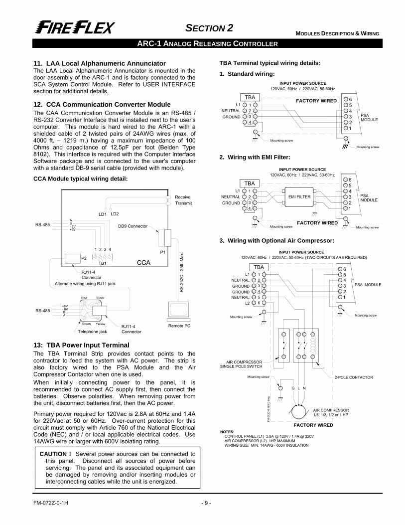
12. CCA Communication Converter Module The CAA Communication Converter Module is an RS-485 / RS-232 Converter Interface that is installed next to the user's computer. This module is hard wired to the ARC-1 with a shielded cable of 2 twisted pairs of 24AWG wires (max. of 4000 ft. – 1219 m.) having a maximum impedance of 100 Ohms and capacitance of 12,5ρF per foot (Belden Type 8102). This interface is required with the Computer Interface Software package and is connected to the user's computer with a standard DB-9 serial cable (provided with module).
CCA Module typical wiring detail:
RS-485
RS
-232
C -
25ft.
Max
.
RS-485
RJ11-4 Connector
Alternate wiring using RJ11 jack
Telephone jack
AB- 8V+8V
Remote PC
- 8V+8V
BA
RJ11-4 Connector
BlackRed
Green Yellow
CCATB1
1 2 3 4
ReceiveTransmit
LD2LD1
DB9 Connector
P1P2
13: TBA Power Input Terminal The TBA Terminal Strip provides contact points to the contractor to feed the system with AC power. The strip is also factory wired to the PSA Module and the Air Compressor Contactor when one is used. When initially connecting power to the panel, it is recommended to connect AC supply first, then connect the batteries. Observe polarities. When removing power from the unit, disconnect batteries first, then the AC power.
Primary power required for 120Vac is 2.8A at 60Hz and 1.4A for 220Vac at 50 or 60Hz. Over-current protection for this circuit must comply with Article 760 of the National Electrical Code (NEC) and / or local applicable electrical codes. Use 14AWG wire or larger with 600V isolating rating.
CAUTION ! Several power sources can be connected to this panel. Disconnect all sources of power before servicing. The panel and its associated equipment can be damaged by removing and/or inserting modules or interconnecting cables while the unit is energized.
TBA Terminal typical wiring details:
1. Standard wiring:
FACTORY WIRED
120VAC, 60Hz / 220VAC, 50-60Hz
Mounting screw
NEUTRALGROUND
234
1
TBAL1
Mounting screw
MODULEPSA
654321
2. Wiring with EMI Filter:
TBA12
43GROUND
NEUTRALL1
120VAC, 60Hz / 220VAC, 50-60HzINPUT POWER SOURCE
Mounting screw
EMI FILTER
FACTORY WIRED
654321
Mounting screw
MODULEPSA
3. Wiring with Optional Air Compressor:
AIR COMPRESSOR
654321
2-POLE CONTACTOR
NEUTRALGROUNDGROUNDNEUTRAL
L1
L2
FACTORY WIRED
AIR COMPRESSORSINGLE POLE SWITCH
NOTES: CONTROL PANEL (L1) 2.8A @ 120V / 1.4A @ 220V AIR COMPRESSOR (L2) 1HP MAXIMUM WIRING SIZE: MIN. 14AWG - 600V INSULATION
L NG
1/6, 1/3, 1/2 or 1 HP
Mounting screw
Mounting screw Mounting screw
34
21
TBA
65
(TWO CIRCUITS ARE REQUIRED)120VAC, 60Hz / 220VAC, 50-60HzINPUT POWER SOURCE
FM-0
72C
-0-1
65 D
.dw
g
MODULES DESCRIPTION & WIRING SECTION 2
ARC-1 ANALOG RELEASING CONTROLLER
- 10 - FM-072Z-0-1H
Preliminary inspection before putting the system into operation 1. Open cabinet door to gain access to the wiring
terminals. Verify that all detection and audible devices are properly connected according to electrical schematics.
2. Connect the 120Vac (220Vac) power on TBA for the control panel (L1) and for the optional air compressor power relay (L2) on two separate branch circuit breakers in the electric distribution panel.
Note: Do not use these circuits breakers for other parallel applications. If necessary, equip each circuit breaker with a security seal or lock in order to avoid accidental closing.
3. Once all the batteries have been wired together, connect the battery cable with the connector on the BCA Module.
4. Always observe polarity when connecting batteries. A blown F1 fuse indicates a short circuit of batteries connection or a polarity reversal connection.
5. Refer to APPENDIX B for battery sizing calculations and APPENDIX C for wiring method.
Note: Batteries have screw type terminals and are provided with a set of factory assembled interconnecting wires, pre-cut and equipped with connecting lugs. It is recommended to connect the back batteries first, then push them at the back of the cabinet before wiring the front set. Precautions should also be taken while wiring the batteries for not making contact or shorts with the live wires !
CAUTION ! Although the batteries provided with the system are sealed, if fractured they can release sulfuric acid which can cause severe burns to the skin and eyes, and can also destroy fabrics. If contact is made with sulfuric acid, immediately flush skin or eyes with water for 15 minutes and seek immediate medical attention.
6. Upon powering up, the panel will go through its start-up routine. The green lamp identified AC POWER should be illuminated and the Alphanumeric Display will show a scrolling SYSTEM RESET indication, then PnP IN PROGRESS and finally show its default screen (see USER INTERFACE section for additional details).
SECTION 3 USER INTERFACE ARC-1 ANALOG RELEASING CONTROLLER
FM-072Z-0-1H - 11 -
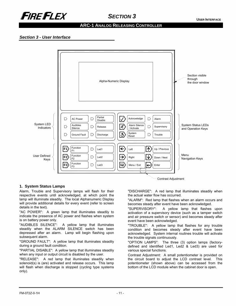
Section 3 - User Interface
F1
F2
F3
AudiblesSilence
Ground Fault SystemReset
PartialDisableAC Power Alarm
Supervisory
Trouble
Alpha-Numeric Display
System Status LEDs and Operation Keys
MenuNavigation Keys
User DefinedKeys
System LEDIndicators
Alarm Silence/ ActivateRelease
Acknowledge
Discharge
EnterMenu / ExitFunctionF3
FunctionF2
FunctionF1 Led1
Led2
Led3
Section visible throughthe door window
Left
Right
Up / Previous
Down / Next
Contrast Adjustment
1. System Status Lamps Alarm, Trouble and Supervisory lamps will flash for their respective events until acknowledged, at which point the lamp will illuminate steadily. The local Alphanumeric Display will provide additional details for every event (refer to screen details in the text). "AC POWER": A green lamp that illuminates steadily to indicate the presence of AC power and flashes when system is on battery power only. "AUDIBLES SILENCE": A yellow lamp that illuminates steadily when the ALARM SILENCE switch has been depressed after an alarm. Lamp will begin flashing upon subsequent alarm. "GROUND FAULT": A yellow lamp that illuminates steadily during a ground fault condition. "PARTIAL DISABLE": A yellow lamp that illuminates steadily when any input or output circuit is disabled by the user. "RELEASE": A red lamp that illuminates steadily when solenoid(s) is (are) activated and release occurs. This lamp will flash when discharge is stopped (cycling type systems only).
"DISCHARGE": A red lamp that illuminates steadily when the actual water flow has occurred. "ALARM": Red lamp that flashes when an alarm occurs and becomes steady after event have been acknowledged. "SUPERVISORY": A yellow lamp that flashes upon activation of a supervisory device (such as a tamper switch and air pressure switch or sensor) and becomes steady after event have been acknowledged. "TROUBLE": A yellow lamp that flashes for any trouble condition and becomes steady after event have been acknowledged. System internal routines trouble will activate the trouble signals continuously. "OPTION LAMPS": The three (3) option lamps (factory-defined and identified Led1, Led2 & Led3) are used for various special functions. Contrast Adjustment: A small potentiometer is provided on the circuit board to adjust the LCD contrast level. This potentiometer (shown above) can be accessed from the bottom of the LCD module when the cabinet door is open.
USER INTERFACE SECTION 3
ARC-1 ANALOG RELEASING CONTROLLER
- 12 - FM-072Z-0-1H
2. Keyboard - System Main Control Keys System is provided with a membrane type keyboard as shown on the previous page. Local sounder will beep once every time a valid control key is depressed. Sounder will beep twice anytime an invalid entry is made or user is scrolling too fast with the navigation keys. Various system main control keys are described below:
ACKNOWLEDGE: Every new event must be acknowledged. Depressing this key will acknowledge
alarms, supervisory and troubles while in their respective events screen. The panel has alarm and trouble resound with lamp flash on subsequent events with alphanumeric annunciation. The flashing lamp turns steady and the local sounder is silenced once all events have been acknowledged.
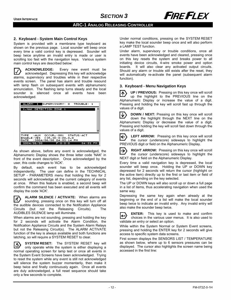
As shown above, before any event is acknowledged, the Alphanumeric Display shows the three letter code 'NAK' in front of the event description. Once acknowledged by the user, this code changes to 'ACK'. By default, each event has to be acknowledged independently. The user can define in the TECHNICAL SETUP - PARAMETERS menu that holding the key for 2 seconds will acknowledge all the current category of events at once. When this feature is enabled, a second beep will confirm the command has been executed and all events will display the code 'ACK'.
ALARM SILENCE / ACTIVATE: When alarms are sounding, pressing once on this key will turn off all
the audible devices connected to the Notification Appliance Circuits (but not the Releasing Circuits). The AUDIBLES SILENCE lamp will illuminate. When alarms are not sounding, pressing and holding the key for 2 seconds will activate the Alarm Condition, the Notification Appliance Circuits and the System Alarm Relays but not the Releasing Circuit(s). The ALARM ACTIVATE function of the key is always available and both functions are latching, so will require a SYSTEM RESET to clear.
SYSTEM RESET: The SYSTEM RESET key will only operate while the system is either displaying a
normal operating screen for lamp test or once all events in the System Event Screens have been acknowledged. Trying to reset the system while any event is still not acknowledged will silence the system buzzer momentarily, then make it beep twice and finally continuously again. Once all events are duly acknowledged, a full reset sequence should take only a few seconds to complete.
Under normal conditions, pressing on the SYSTEM RESET key make the local sounder beep once and will also perform a LAMP TEST function. Under alarm, supervisory or trouble conditions, once all events have been acknowledged and cleared, pressing once on this key resets the system and breaks power to all initiating device circuits, 4-wire smoke power and option boards. It will also clear any activated output circuits. Should any alarm or trouble still exists after the reset, they will automatically re-activate the panel (subsequent alarm function).
3. Keyboard - Menu Navigation Keys UP / PREVIOUS: Pressing on this key once will scroll up the highlight to the PREVIOUS line on the
Alphanumeric Display or increase the value of a digit. Pressing and holding the key will scroll fast up through the values of a digit.
DOWN / NEXT: Pressing on this key once will scroll down the highlight through the NEXT line on the
Alphanumeric Display or decrease the value of a digit. Pressing and holding the key will scroll fast down through the values of a digit.
LEFT ARROW: Pressing on this key once will scroll the cursor (underscore) sideways to highlight the
PREVIOUS digit or field on the Alphanumeric Display.
RIGHT ARROW: Pressing on this key once will scroll the cursor (underscore) sideways to highlight the
NEXT digit or field on the Alphanumeric Display. Every time a valid navigation key is depressed, the local sounder will beep once. Holding the UP or DOWN key depressed for 2 seconds will return the cursor (highlight on the active item) directly up to the first or last item or field of any list, depending on the key selected. The UP or DOWN keys will also scroll up or down a full page in a list of items, thus accelerating navigation when used the same way. Depressing the same key again when already at the beginning or the end of a list will make the local sounder beep twice to indicate an invalid entry. Any invalid entry will also make the sounder beep twice.
ENTER: This key is used to make and confirm choices in the various user menus. It is also used to
validate an entry or select an option. While within the System Normal or System Event screens, pressing and holding the ENTER key for 2 seconds will give access to specific system data screens. First screen displays the SENSORS LIST / TEMPERATURE as shown below, where up to 6 sensors pressures can be displayed. The cursor also highlights the screen name being accessed in the first line:
SECTION 3 USER INTERFACE ARC-1 ANALOG RELEASING CONTROLLER
FM-072Z-0-1H - 13 -
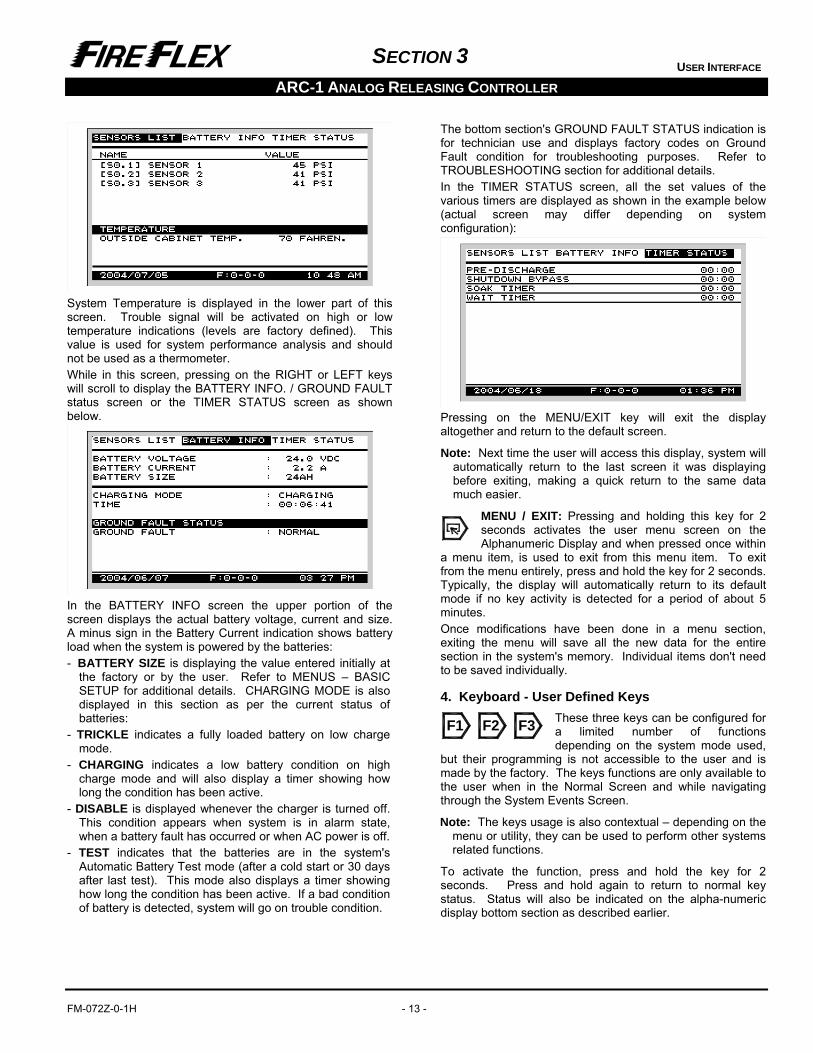
System Temperature is displayed in the lower part of this screen. Trouble signal will be activated on high or low temperature indications (levels are factory defined). This value is used for system performance analysis and should not be used as a thermometer. While in this screen, pressing on the RIGHT or LEFT keys will scroll to display the BATTERY INFO. / GROUND FAULT status screen or the TIMER STATUS screen as shown below.
In the BATTERY INFO screen the upper portion of the screen displays the actual battery voltage, current and size. A minus sign in the Battery Current indication shows battery load when the system is powered by the batteries: - BATTERY SIZE is displaying the value entered initially at
the factory or by the user. Refer to MENUS – BASIC SETUP for additional details. CHARGING MODE is also displayed in this section as per the current status of batteries:
- TRICKLE indicates a fully loaded battery on low charge mode.
- CHARGING indicates a low battery condition on high charge mode and will also display a timer showing how long the condition has been active.
- DISABLE is displayed whenever the charger is turned off. This condition appears when system is in alarm state, when a battery fault has occurred or when AC power is off.
- TEST indicates that the batteries are in the system's Automatic Battery Test mode (after a cold start or 30 days after last test). This mode also displays a timer showing how long the condition has been active. If a bad condition of battery is detected, system will go on trouble condition.
The bottom section's GROUND FAULT STATUS indication is for technician use and displays factory codes on Ground Fault condition for troubleshooting purposes. Refer to TROUBLESHOOTING section for additional details. In the TIMER STATUS screen, all the set values of the various timers are displayed as shown in the example below (actual screen may differ depending on system configuration):
Pressing on the MENU/EXIT key will exit the display altogether and return to the default screen.
Note: Next time the user will access this display, system will automatically return to the last screen it was displaying before exiting, making a quick return to the same data much easier.
MENU / EXIT: Pressing and holding this key for 2 seconds activates the user menu screen on the Alphanumeric Display and when pressed once within
a menu item, is used to exit from this menu item. To exit from the menu entirely, press and hold the key for 2 seconds. Typically, the display will automatically return to its default mode if no key activity is detected for a period of about 5 minutes. Once modifications have been done in a menu section, exiting the menu will save all the new data for the entire section in the system's memory. Individual items don't need to be saved individually.
4. Keyboard - User Defined Keys These three keys can be configured for a limited number of functions depending on the system mode used,
but their programming is not accessible to the user and is made by the factory. The keys functions are only available to the user when in the Normal Screen and while navigating through the System Events Screen.
Note: The keys usage is also contextual – depending on the menu or utility, they can be used to perform other systems related functions.
To activate the function, press and hold the key for 2 seconds. Press and hold again to return to normal key status. Status will also be indicated on the alpha-numeric display bottom section as described earlier.
F1 F2 F3
USER INTERFACE SECTION 3
ARC-1 ANALOG RELEASING CONTROLLER
- 14 - FM-072Z-0-1H
5. Local Alphanumeric Display The ARC-1® Analog Release Controller is provided with a local Alphanumeric Display, Model LAA, mounted on the front door that provides detailed indications for status display, operation and programming of the system. It is provided with a soft membrane keyboard accessible by opening the front key locked door. The alphanumeric display and the main indicating lamps are visible through the door window at all times. Upon initial power up, the local sounder will be heard for 2 seconds then will automatically stop. At the same time, the Alphanumeric Display will become momentarily blank and then will show a scrolling "System Reset" indication. It will also momentarily display the "P&P in Progress" indication while the system's Plug and Play routine is executed.
Note: The Plug & Play routine is automatically verifying system integrity and module placement at both the initial start-up and system reset.
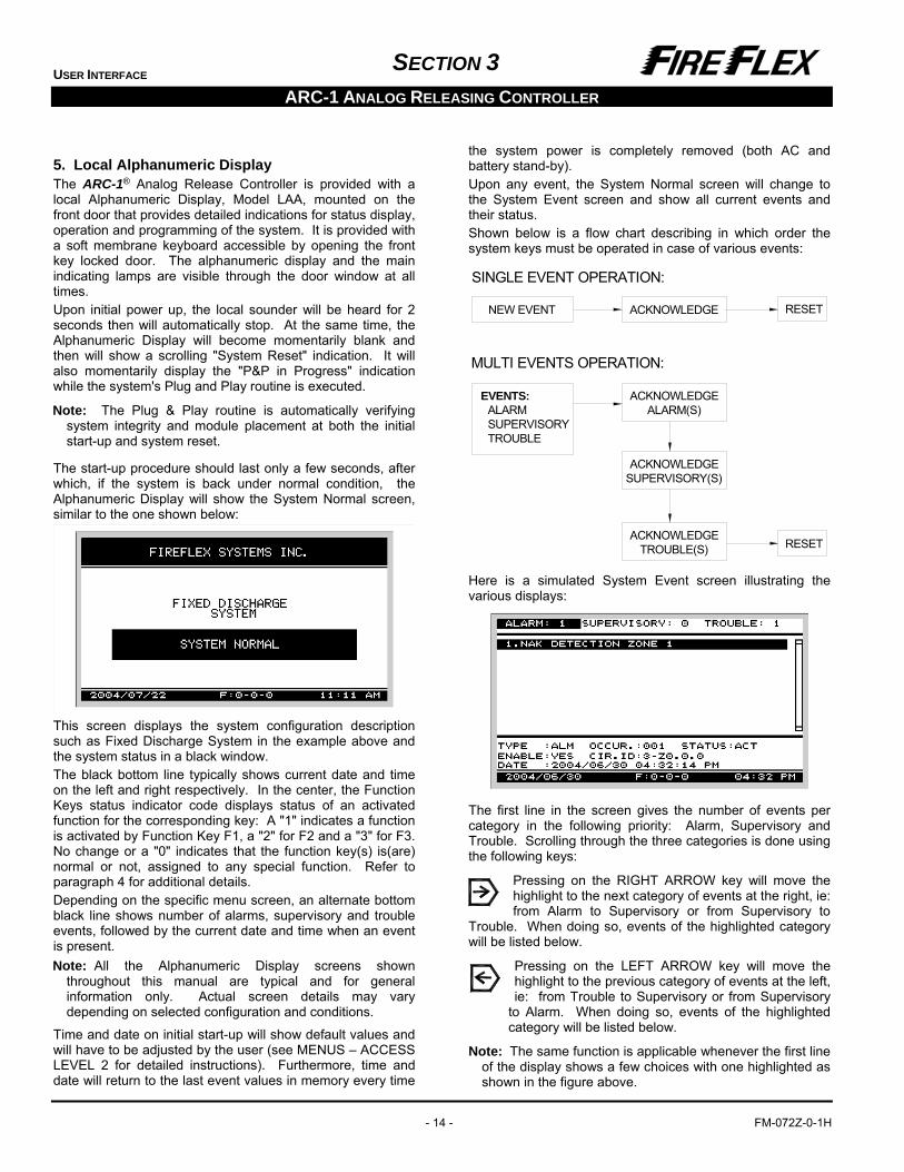
The start-up procedure should last only a few seconds, after which, if the system is back under normal condition, the Alphanumeric Display will show the System Normal screen, similar to the one shown below:
This screen displays the system configuration description such as Fixed Discharge System in the example above and the system status in a black window. The black bottom line typically shows current date and time on the left and right respectively. In the center, the Function Keys status indicator code displays status of an activated function for the corresponding key: A "1" indicates a function is activated by Function Key F1, a "2" for F2 and a "3" for F3. No change or a "0" indicates that the function key(s) is(are) normal or not, assigned to any special function. Refer to paragraph 4 for additional details. Depending on the specific menu screen, an alternate bottom black line shows number of alarms, supervisory and trouble events, followed by the current date and time when an event is present. Note: All the Alphanumeric Display screens shown
throughout this manual are typical and for general information only. Actual screen details may vary depending on selected configuration and conditions.
Time and date on initial start-up will show default values and will have to be adjusted by the user (see MENUS – ACCESS LEVEL 2 for detailed instructions). Furthermore, time and date will return to the last event values in memory every time
the system power is completely removed (both AC and battery stand-by). Upon any event, the System Normal screen will change to the System Event screen and show all current events and their status. Shown below is a flow chart describing in which order the system keys must be operated in case of various events:
NEW EVENT ACKNOWLEDGE RESET
ACKNOWLEDGEALARM(S)
EVENTS: ALARM SUPERVISORY TROUBLE
RESET
ACKNOWLEDGESUPERVISORY(S)
ACKNOWLEDGETROUBLE(S)
SINGLE EVENT OPERATION:
MULTI EVENTS OPERATION:
Here is a simulated System Event screen illustrating the various displays:
The first line in the screen gives the number of events per category in the following priority: Alarm, Supervisory and Trouble. Scrolling through the three categories is done using the following keys:
Pressing on the RIGHT ARROW key will move the highlight to the next category of events at the right, ie: from Alarm to Supervisory or from Supervisory to
Trouble. When doing so, events of the highlighted category will be listed below.
Pressing on the LEFT ARROW key will move the highlight to the previous category of events at the left, ie: from Trouble to Supervisory or from Supervisory
to Alarm. When doing so, events of the highlighted category will be listed below.
Note: The same function is applicable whenever the first line of the display shows a few choices with one highlighted as shown in the figure above.

SECTION 3 USER INTERFACE ARC-1 ANALOG RELEASING CONTROLLER
FM-072Z-0-1H - 15 -
Current events are displayed in the list, identified as 'NAK' for Not Acknowledged, or 'ACK' for Acknowledged, the first event remaining highlighted until acknowledged. Up to 99 events are displayed per screen – (for the full list of events, use the EVENTS LOG). Note the cursor at the right side of the screen. The position of the black square indicates how far in the list the display has gone. Next is the technical section, displaying various data for the highlighted event: TYPE is a three letter code displaying which type of event is
highlighted where: ALM = Alarm TBL = Trouble SUP = Supervisory NOP = Not Operated.
OCCUR displays the number of occurrences of the event, which is particularly useful in case of intermittent events to see how many times the event occurred. Total number of occurrences displayed in the even log is factory limited:
- Alarms: 5 - Supervisory: 4 - Troubles: 3
STATUS shows the actual status of the circuit where: ACT = Active NRM = Normal.
ENABLE indicates if the circuit is Enabled (yes) or Disabled (no). CIR.ID displays a 5 digit code used by the factory, describing
module placement, circuit type, zone number and type of activation. Refer to TROUBLESHOOTING in Appendix D for additional details on these codes.
DATE displays the date and time stamp at which the highlighted event occurred.
Note: Alarms have priority and will always override any other event. The alarm screen will always display first and over any other screen that might be displayed at the time of the alarm.
User Menus Priority on alarms: Should an alarm occur on the system during the use of the various user menus, all modifications made before the event will automatically be saved before the Alphanumeric Display will automatically exit the menu and display the Events Screen. Automatic return: At any stage in the various User Menus, should there be no activity for a continuous period of around 5 minutes, the Alphanumeric Display will automatically return to the default stand-by or Events List screen, depending on the system status.
The ARC-1 Analog Releasing Controller provides 4 User Menu levels accessible by pressing and holding the "MENU / EXIT" key for 2 seconds. Local sounder will beep once and the Alphanumeric Display will show the following screen:
The SYSTEM DATA level is accessible to any user without any password and is highlighted by default when entering the menu. Entering this level is done simply by highlighting it and then pressing on the ENTER key. The user can select to access any one of the 4 levels by using the UP / PREVIOUS and DOWN / NEXT keys to scroll through the list. Activation of the selected menu is made by pressing once on the ENTER key but additionally, the BASIC, TECHNICAL and ADVANCED SETUP levels all require a password to be accessed. Pressing ENTER will display the screen shown below:
By default, the first password digit to enter will be underscored. Use navigation keys to scroll and validate the available characters which are numbers 0 to 9 and letters A to C. Pressing on the RIGHT ARROW key once will highlight the next field. Repeat the same method for the next two fields. Once the last digit is entered, pressing once on the ENTER key will validate the entries and give the user access to the selected menu. Exiting this screen is done by pressing on the MENU / EXIT key.
USER INTERFACE SECTION 3
ARC-1 ANALOG RELEASING CONTROLLER
- 16 - FM-072Z-0-1H
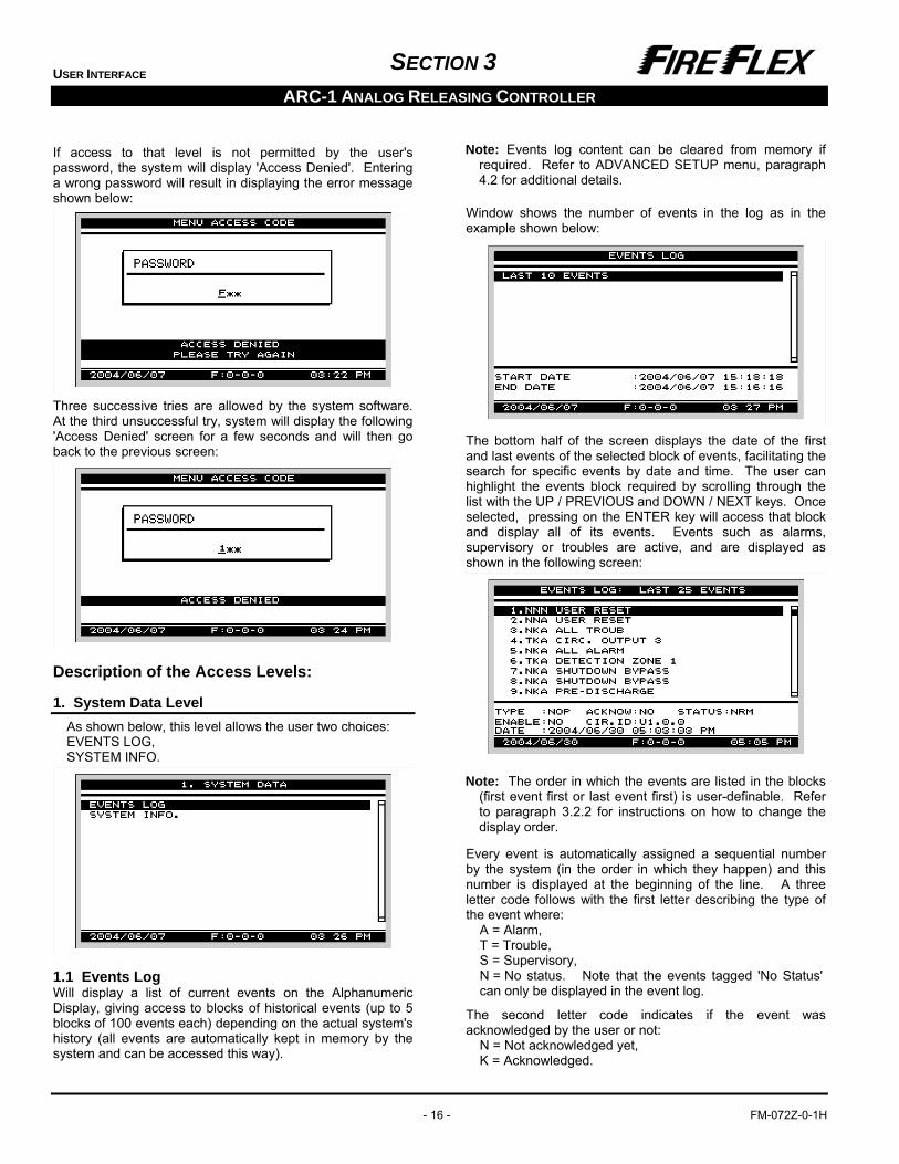
If access to that level is not permitted by the user's password, the system will display 'Access Denied'. Entering a wrong password will result in displaying the error message shown below:
Three successive tries are allowed by the system software. At the third unsuccessful try, system will display the following 'Access Denied' screen for a few seconds and will then go back to the previous screen:
Description of the Access Levels:
1. System Data Level As shown below, this level allows the user two choices: EVENTS LOG, SYSTEM INFO.
1.1 Events Log Will display a list of current events on the Alphanumeric Display, giving access to blocks of historical events (up to 5 blocks of 100 events each) depending on the actual system's history (all events are automatically kept in memory by the system and can be accessed this way).
Note: Events log content can be cleared from memory if required. Refer to ADVANCED SETUP menu, paragraph 4.2 for additional details.
Window shows the number of events in the log as in the example shown below:
The bottom half of the screen displays the date of the first and last events of the selected block of events, facilitating the search for specific events by date and time. The user can highlight the events block required by scrolling through the list with the UP / PREVIOUS and DOWN / NEXT keys. Once selected, pressing on the ENTER key will access that block and display all of its events. Events such as alarms, supervisory or troubles are active, and are displayed as shown in the following screen:
Note: The order in which the events are listed in the blocks (first event first or last event first) is user-definable. Refer to paragraph 3.2.2 for instructions on how to change the display order.
Every event is automatically assigned a sequential number by the system (in the order in which they happen) and this number is displayed at the beginning of the line. A three letter code follows with the first letter describing the type of the event where:
A = Alarm, T = Trouble, S = Supervisory, N = No status. Note that the events tagged 'No Status' can only be displayed in the event log.
The second letter code indicates if the event was acknowledged by the user or not:
N = Not acknowledged yet, K = Acknowledged.
SECTION 3 USER INTERFACE ARC-1 ANALOG RELEASING CONTROLLER
FM-072Z-0-1H - 17 -
The third and last letter code indicates the event status: A = Activated, N = Normal (for a non-latching type device).
A short description of the event then follows on the same line. Next is the technical section, displaying various data for the highlighted event:
TYPE is a three letter code displaying which type of event is highlighted where:
ALM = Alarm TBL = Trouble SUP = Supervisory NOP = Not Operated.
ACKNOW shows if the highlighted event was previously acknowledged (YES) or not (NO).
STATUS shows the actual status of the circuit where: ACT = Active NRM = Normal.
ENABLE indicates if the circuit is Enabled (yes) or Disabled (no).
CIR.ID displays a 5 digit code used by the factory, describing module placement, circuit type, zone number and type of activation. Refer to TROUBLESHOOTING in Appendix D for additional details on these codes.
DATE displays the date and time stamp at which the highlighted event occurred.
Internal system events can also be intermixed within the list of actual events such as alarms, troubles and supervisory. Once scrolling through the list is completed, pressing on the MENU / EXIT key once will return the user to the EVENTS LOG screen where other blocks of events, if present, can be displayed in the same manner. Pressing on the MENU / EXIT key again in that screen will return the user to the Level 1 menu screen.
NOTE: Some events may not log properly when system is under battery trouble condition. Battery maintenance should always be done as soon as possible when trouble occur.
1.2 System Information Will display information about the system such as its firmware version, flash I.D. and Serial number. Then follows its Verification Code, Mode, Panel Identification, Network Information and IP address if applicable:
The VERIF. CODE can be used if the user has forgotten his password to contact FireFlex Product Support Department and get a reminder.
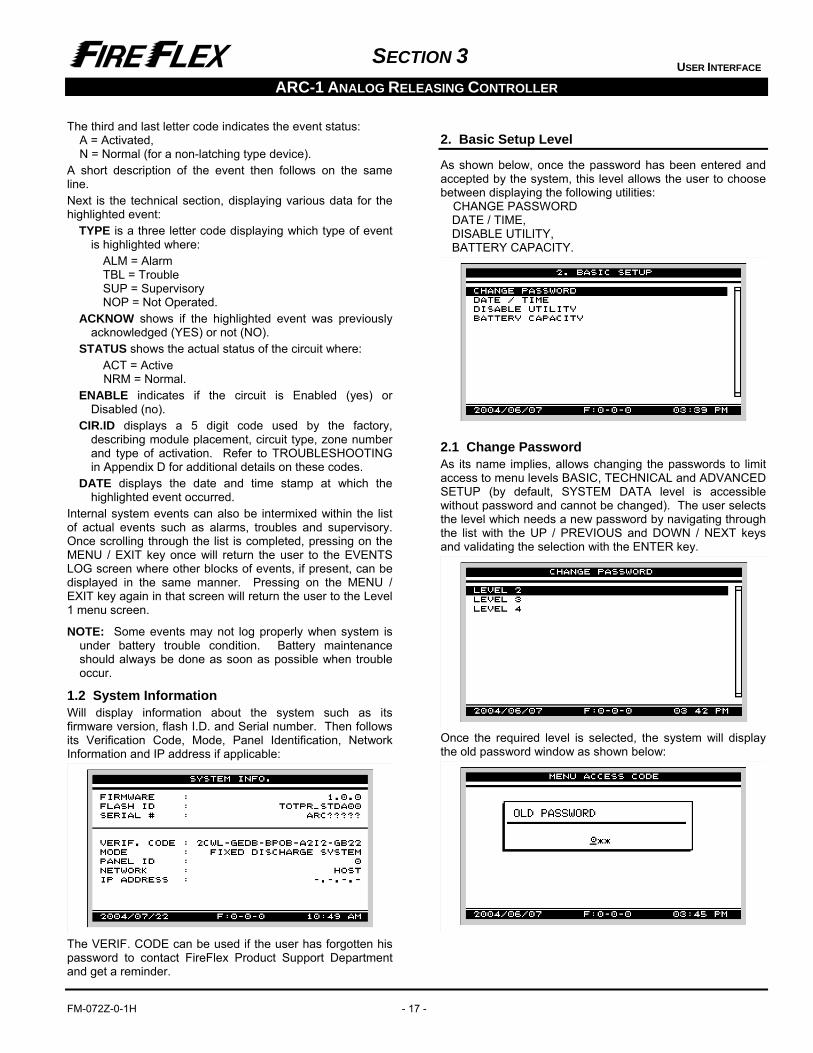
2. Basic Setup Level
As shown below, once the password has been entered and accepted by the system, this level allows the user to choose between displaying the following utilities:
CHANGE PASSWORD DATE / TIME, DISABLE UTILITY, BATTERY CAPACITY.
2.1 Change Password As its name implies, allows changing the passwords to limit access to menu levels BASIC, TECHNICAL and ADVANCED SETUP (by default, SYSTEM DATA level is accessible without password and cannot be changed). The user selects the level which needs a new password by navigating through the list with the UP / PREVIOUS and DOWN / NEXT keys and validating the selection with the ENTER key.
Once the required level is selected, the system will display the old password window as shown below:

USER INTERFACE SECTION 3
ARC-1 ANALOG RELEASING CONTROLLER
- 18 - FM-072Z-0-1H
Entering any higher level password will also allow changing the access password to that level. Once in the menu, the system will display the NEW PASSWORD set-up screen shown below:
Using a random combination of numbers and letters is the preferred way of using passwords to make the system safer against unauthorized entry. Scrolling through all the letters and numbers is done with the UP / PREVIOUS and DOWN / NEXT keys (numbers 0 to 9 and letters A to C). Once the digit is selected, press on the ENTER key to move the cursor to the next field. Repeat the same sequence for all fields requiring a change. Pressing on the LEFT ARROW key once will erase the last digit and move the cursor left. Alternately, pressing on the RIGHT ARROW key once will move the cursor to the right and display the number '0'. Pressing once on the ENTER key after the last digit is entered will validate the complete change. After a short delay, the system will display the following screen, asking to confirm by re-entering the entire password:
Note: Should the user enter a different code in the
confirmation, system will display 'UNMATCHED CODE' and request to enter the proper code again.
Pressing on the MENU / EXIT key will return the user to the NEW PASSWORD screen. Once the new password is confirmed, system will automatically display a confirmation screen (shown below) and register the new password, then return the user to the CHANGE PASWORD screen.
The same procedure is followed for any other password change required.
Note: Carefully write down the new password and keep in a safe location for future reference. Do not keep passwords in the panel enclosure !
2.2 Date / Time Will display the following screen, allowing the user to change the system's date and time:
Simply use the navigation keys to underscore the field needing adjustment and adjust by scrolling up and down, as described in the Menu Navigation Keys description. Exiting the utility by pressing on the ENTER key will automatically update the system clock to the new values entered.
Note: Time in this screen is always displayed in the 24 hours format as shown above. Change to the display format will only show in the last line of the alpha-numeric display (12 hrs format shown above).
SECTION 3 USER INTERFACE ARC-1 ANALOG RELEASING CONTROLLER
FM-072Z-0-1H - 19 -
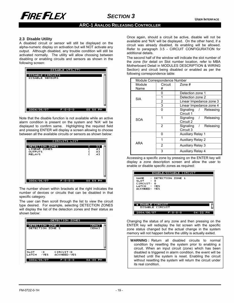
2.3 Disable Utility A disabled circuit or sensor will still be displayed on the alpha-numeric display on activation but will NOT activate any output. Although disabled, any trouble condition will still be activated normally. The utility will allow choosing between disabling or enabling circuits and sensors as shown in the following screen:
Note that the disable function is not available while an active alarm condition is present on the system and 'N/A' will be displayed to confirm same. Highlighting the required field and pressing ENTER will display a screen allowing to choose between all the available circuits or sensors as shown below:
The number shown within brackets at the right indicates the number of devices or circuits that can be disabled in that specific category. The user can then scroll through the list to view the circuit type desired. For example, selecting DETECTION ZONES will display the list of the detection zones and their status as shown below:
Once again, should a circuit be active, disable will not be available and 'N/A' will be displayed. On the other hand, if a circuit was already disabled, its enabling will be allowed. Refer to paragraph 3.5 - CIRCUIT CONFIGURATION for additional details. The second half of the window will indicate the slot number of the zone (for detail on Slot number location, refer to MBA Motherboard Detail in MODULES DESCRIPTION & WIRING Section) and circuit being disabled or enabled as per the following correspondence table:
Module Correspondence Number Module Name
Circuit #
Zone #
0 Detection zone 1 1 Detection zone 2 2 Linear Impedance zone 3
SIA
3 Linear Impedance zone 4 0 Signaling / Releasing
Circuit 1 1 Signaling / Releasing
Circuit 2 SOA
2 Signaling / Releasing Circuit 3
0 Auxiliary Relay 1 1 Auxiliary Relay 2 2 Auxiliary Relay 3 ARA
3 Auxiliary Relay 4
Accessing a specific zone by pressing on the ENTER key will display a zone description screen and allow the user to enable or disable specific zones as required:
Changing the status of any zone and then pressing on the ENTER key will redisplay the list screen with the specific zone status changed but the actual change in the system memory will not happen before the utility is actually exited.
WARNING : Return all disabled circuits to normal condition by resetting the system prior to enabling a circuit. When an input circuit (zone) which has been disabled is triggered in alarm condition, the event will be latched until the system is reset. Enabling the circuit without resetting the system will return the circuit under its real condition.
USER INTERFACE SECTION 3
ARC-1 ANALOG RELEASING CONTROLLER
- 20 - FM-072Z-0-1H
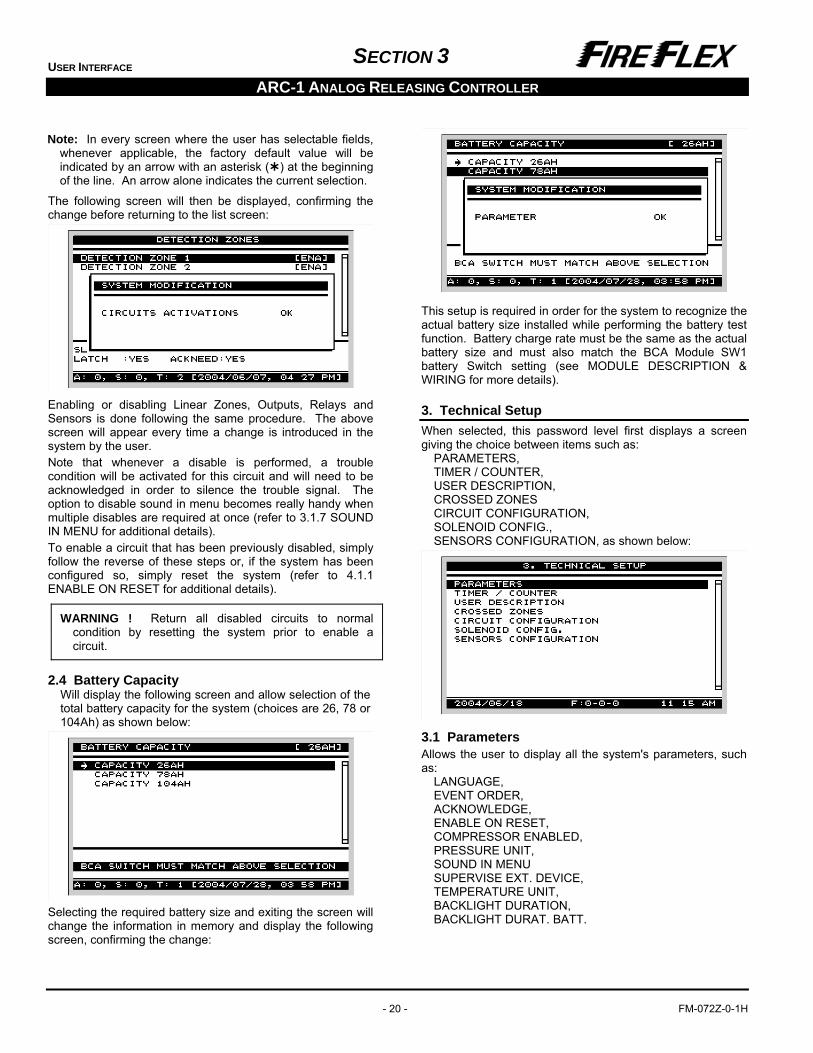
Note: In every screen where the user has selectable fields, whenever applicable, the factory default value will be indicated by an arrow with an asterisk ( ) at the beginning of the line. An arrow alone indicates the current selection.
The following screen will then be displayed, confirming the change before returning to the list screen:
Enabling or disabling Linear Zones, Outputs, Relays and Sensors is done following the same procedure. The above screen will appear every time a change is introduced in the system by the user. Note that whenever a disable is performed, a trouble condition will be activated for this circuit and will need to be acknowledged in order to silence the trouble signal. The option to disable sound in menu becomes really handy when multiple disables are required at once (refer to 3.1.7 SOUND IN MENU for additional details). To enable a circuit that has been previously disabled, simply follow the reverse of these steps or, if the system has been configured so, simply reset the system (refer to 4.1.1 ENABLE ON RESET for additional details).
WARNING ! Return all disabled circuits to normal condition by resetting the system prior to enable a circuit.
2.4 Battery Capacity Will display the following screen and allow selection of the total battery capacity for the system (choices are 26, 78 or 104Ah) as shown below:
Selecting the required battery size and exiting the screen will change the information in memory and display the following screen, confirming the change:
This setup is required in order for the system to recognize the actual battery size installed while performing the battery test function. Battery charge rate must be the same as the actual battery size and must also match the BCA Module SW1 battery Switch setting (see MODULE DESCRIPTION & WIRING for more details).
3. Technical Setup When selected, this password level first displays a screen giving the choice between items such as:
PARAMETERS, TIMER / COUNTER, USER DESCRIPTION, CROSSED ZONES CIRCUIT CONFIGURATION, SOLENOID CONFIG., SENSORS CONFIGURATION, as shown below:
3.1 Parameters Allows the user to display all the system's parameters, such as:
LANGUAGE, EVENT ORDER, ACKNOWLEDGE, ENABLE ON RESET, COMPRESSOR ENABLED, PRESSURE UNIT, SOUND IN MENU SUPERVISE EXT. DEVICE, TEMPERATURE UNIT, BACKLIGHT DURATION, BACKLIGHT DURAT. BATT.
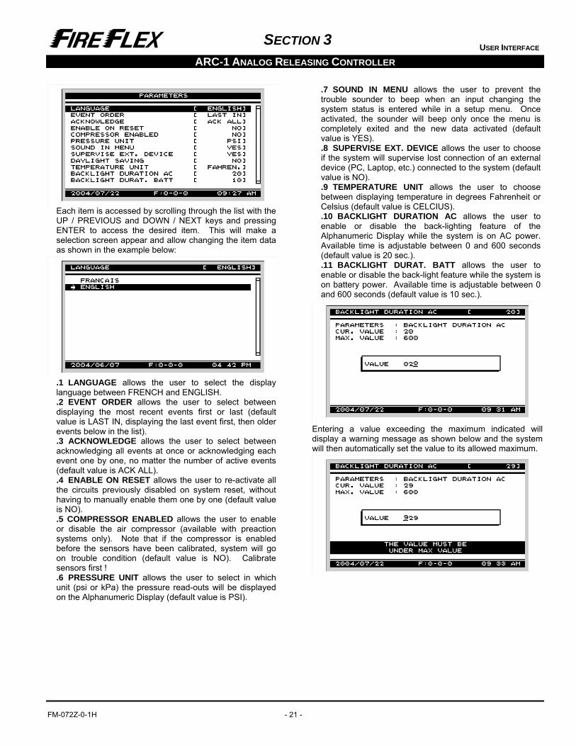
SECTION 3 USER INTERFACE ARC-1 ANALOG RELEASING CONTROLLER
FM-072Z-0-1H - 21 -
Each item is accessed by scrolling through the list with the UP / PREVIOUS and DOWN / NEXT keys and pressing ENTER to access the desired item. This will make a selection screen appear and allow changing the item data as shown in the example below:
.1 LANGUAGE allows the user to select the display language between FRENCH and ENGLISH. .2 EVENT ORDER allows the user to select between displaying the most recent events first or last (default value is LAST IN, displaying the last event first, then older events below in the list). .3 ACKNOWLEDGE allows the user to select between acknowledging all events at once or acknowledging each event one by one, no matter the number of active events (default value is ACK ALL). .4 ENABLE ON RESET allows the user to re-activate all the circuits previously disabled on system reset, without having to manually enable them one by one (default value is NO). .5 COMPRESSOR ENABLED allows the user to enable or disable the air compressor (available with preaction systems only). Note that if the compressor is enabled before the sensors have been calibrated, system will go on trouble condition (default value is NO). Calibrate sensors first ! .6 PRESSURE UNIT allows the user to select in which unit (psi or kPa) the pressure read-outs will be displayed on the Alphanumeric Display (default value is PSI).
.7 SOUND IN MENU allows the user to prevent the trouble sounder to beep when an input changing the system status is entered while in a setup menu. Once activated, the sounder will beep only once the menu is completely exited and the new data activated (default value is YES). .8 SUPERVISE EXT. DEVICE allows the user to choose if the system will supervise lost connection of an external device (PC, Laptop, etc.) connected to the system (default value is NO). .9 TEMPERATURE UNIT allows the user to choose between displaying temperature in degrees Fahrenheit or Celsius (default value is CELCIUS). .10 BACKLIGHT DURATION AC allows the user to enable or disable the back-lighting feature of the Alphanumeric Display while the system is on AC power. Available time is adjustable between 0 and 600 seconds (default value is 20 sec.). .11 BACKLIGHT DURAT. BATT allows the user to enable or disable the back-light feature while the system is on battery power. Available time is adjustable between 0 and 600 seconds (default value is 10 sec.).
Entering a value exceeding the maximum indicated will display a warning message as shown below and the system will then automatically set the value to its allowed maximum.

USER INTERFACE SECTION 3
ARC-1 ANALOG RELEASING CONTROLLER
- 22 - FM-072Z-0-1H
Pressing on the ENTER key will update the value in the list but it will not be updated in the system memory until the utility is exited (default value is 10 seconds). On exiting this menu, the system will display a modification screen, confirming and processing the change as shown below (typical for every change throughout the various menus):
3.2 Timers / Counters Will access the setup utility for the various timers and counters included in the system program. More information on each timer and counter usage is available in the FACTORY PROGRAMMING section. The following setup screen is displayed when this function is selected:
Note: Actual timers list will vary depending on system configuration.
This menu allows the user to adjust the value of various timers and counters, depending on the system's factory set configuration. For example, selecting PRE-DISCHARGE as shown above will display the following screen:
This screen displays the current timer name and set value, followed by the maximum value this timer can be set to. Simply use the navigation keys to underscore the field needing adjustment and adjust by scrolling up and down, as described in the Menu Navigation Keys section. On exiting this menu, the system will display a modification screen, confirming and processing the change. Refer to FACTORY PROGRAMMING section for additional details on timers.
3.3 User Description Will allow the user to access the circuit list, allowing to display and / or change the description of the zones as they will appear on the Alphanumeric Display. The utility will first display a screen called CIRCUIT LIST where the user will select which category of circuits he wants to access as shown below:
Once the choice is highlighted, pressing on the ENTER key will display the list of circuits on this category. As shown in the example below:
Selecting an entry and pressing on the ENTER key will display the following screen and allow writing and enabling a user message for this circuit.

SECTION 3 USER INTERFACE ARC-1 ANALOG RELEASING CONTROLLER
FM-072Z-0-1H - 23 -
DEFAULT MESSAGE is the message defined at the factory which can be accessed and displayed at any time.
CURRENT MESSAGE displays the message currently assigned to this zone. If the user has not assigned a different name, the system will display the default factory message again.
The second half of the screen (with a border) is a utility that allows the user to define his own message and have it displayed on the Alphanumeric Display in lieu of the default factory message. Deactivating the user message by entering "NO" will display the default factory message no matter what the user may have entered previously but entering "YES" will allow the user to enter or edit his own message. Note: Maximum number of characters is limited to 30 per
user defined message. Whatever message is entered by the user will not be changed if a different language is selected. Custom messages will have to be changed manually.
While the user is in this menu, pressing once of the F1 key will delete the last character of the line. Pressing once on the F2 key will add the letter "A" at the end of the line, which the user can now edit by scrolling through the available characters using the UP / PREVIOUS and DOWN / NEXT keys. The LEFT ARROW and RIGHT ARROW keys are also available to move laterally in the message for editing.
3.4 Crossed Zones Gives the user access to the zone groups as shown on the following screen where they can be defined as single or cross-zoned by selecting the zone group to modify as shown here:
Once selected by pressing on the ENTER key, the group can be assigned to operate in cross-zone as shown below. Note that only zones 1 and 2 in a specific group can be configured as Cross-Zoned.
The concept of Detection Groups is more clearly described in the FACTORY PROGRAMMING section.
3.5 Circuit Configuration Will display the Circuits List screen again, showing all the types of input and output circuits configured in the system. Once in the utility, selecting one item and pressing on the ENTER key will display the circuits of the type selected and their settings. Typically, when selecting a category, the system will display a list of all the circuits or zones in this category with their actual settings. The lower half of this screen will also display technical information such as the slot location and technical settings of the highlighted item. Changing the setup of a circuit by selecting a choice and then pressing on ENTER will redisplay the previous screen. The value changed and this new value will be recorded in the system memory as soon as the MENU / EXIT key is depressed. Assigning a specific value to an output can be quite handy when commissioning a system, for example, to confirm that a specific action is indeed reported by the system.
.1 DETECTION ZONES will display the list of zones and their current mode.
User has the choice between two settings:
(ALO) Alarm Latching with N.O. contacts. (ANC) Alarm Non-latching with N.C. contacts.
Module Correspondence Number Module Name
Circuit # Zone #
0 Detection zone 1 SIA 1 Detection zone 2
Selecting one allows the user to modify its factory assigned setting as shown in the screen below:
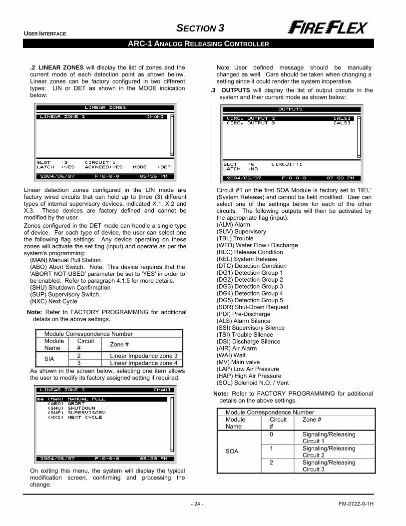
USER INTERFACE SECTION 3
ARC-1 ANALOG RELEASING CONTROLLER
- 24 - FM-072Z-0-1H
.2 LINEAR ZONES will display the list of zones and the current mode of each detection point as shown below. Linear zones can be factory configured in two different types: LIN or DET as shown in the MODE indication below:
Linear detection zones configured in the LIN mode are factory wired circuits that can hold up to three (3) different types of internal supervisory devices, indicated X.1, X.2 and X.3. These devices are factory defined and cannot be modified by the user. Zones configured in the DET mode can handle a single type of device. For each type of device, the user can select one the following flag settings. Any device operating on these zones will activate the set flag (input) and operate as per the system's programming:
(MAN) Manual Pull Station. (ABO) Abort Switch. Note: This device requires that the 'ABORT NOT USED' parameter be set to 'YES' in order to be enabled. Refer to paragraph 4.1.5 for more details. (SHU) Shutdown Confirmation (SUP) Supervisory Switch. (NXC) Next Cycle
Note: Refer to FACTORY PROGRAMMING for additional details on the above settings.
Module Correspondence Number Module Name
Circuit # Zone #
2 Linear Impedance zone 3 SIA 3 Linear Impedance zone 4
As shown in the screen below, selecting one item allows the user to modify its factory assigned setting if required:
On exiting this menu, the system will display the typical modification screen, confirming and processing the change.
Note: User defined message should be manually changed as well. Care should be taken when changing a setting since it could render the system inoperative.
.3 OUTPUTS will display the list of output circuits in the system and their current mode as shown below:
Circuit #1 on the first SOA Module is factory set to 'REL' (System Release) and cannot be field modified. User can select one of the settings below for each of the other circuits. The following outputs will then be activated by the appropriate flag (input): (ALM) Alarm (SUV) Supervisory (TBL) Trouble (WFD) Water Flow / Discharge (RLC) Release Condition (REL) System Release (DTC) Detection Condition (DG1) Detection Group 1 (DG2) Detection Group 2 (DG3) Detection Group 3 (DG4) Detection Group 4 (DG5) Detection Group 5 (SDR) Shut-Down Request (PDI) Pre-Discharge (ALS) Alarm Silence (SSI) Supervisory Silence (TSI) Trouble Silence (DSI) Discharge Silence (AIR) Air Alarm (WAI) Wait (MV) Main valve (LAP) Low Air Pressure (HAP) High Air Pressure (SOL) Solenoid N.O. / Vent
Note: Refer to FACTORY PROGRAMMING for additional details on the above settings.
Module Correspondence Number Module Name
Circuit #
Zone #
0 Signaling/Releasing Circuit 1
1 Signaling/Releasing Circuit 2 SOA
2 Signaling/Releasing Circuit 3
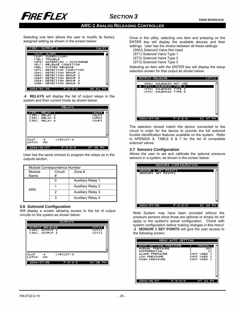
SECTION 3 USER INTERFACE ARC-1 ANALOG RELEASING CONTROLLER
FM-072Z-0-1H - 25 -
Selecting one item allows the user to modify its factory assigned setting as shown in the screen below:
.4 RELAYS will display the list of output relays in the system and their current mode as shown below:
User has the same choices to program the relays as in the outputs section.
Module Correspondence Number Module Name
Circuit #
Zone #
0 Auxiliary Relay 1 1 Auxiliary Relay 2 2 Auxiliary Relay 3
ARA
3 Auxiliary Relay 4
3.6 Solenoid Configuration Will display a screen allowing access to the list of output circuits on the system as shown below:
Once in the utility, selecting one item and pressing on the ENTER key will display the available devices and their settings. User has the choice between all these settings:
(SNU) Solenoid Valve Not Used (ST1) Solenoid Valve Type 1 (ST2) Solenoid Valve Type 2 (ST3) Solenoid Valve Type 3
Selecting an item with the ENTER key will display the setup selection screen for that output as shown below:
The selection should match the device connected to the circuit in order for the device to provide the full solenoid trouble identification features available on the system. Refer to APENDIX A, TABLE 6 & 7 for the list of compatible solenoid valves.
3.7 Sensors Configuration Allows the user to set and calibrate the optional pressure sensors in a system, as shown in the screen below:
Note: System may have been provided without the pressure sensors since those are optional or simply do not apply to the system's actual configuration. Check with system configuration before making changes in this menu! .1 SENSOR 1 SET POINTS will give the user access to the following screen:
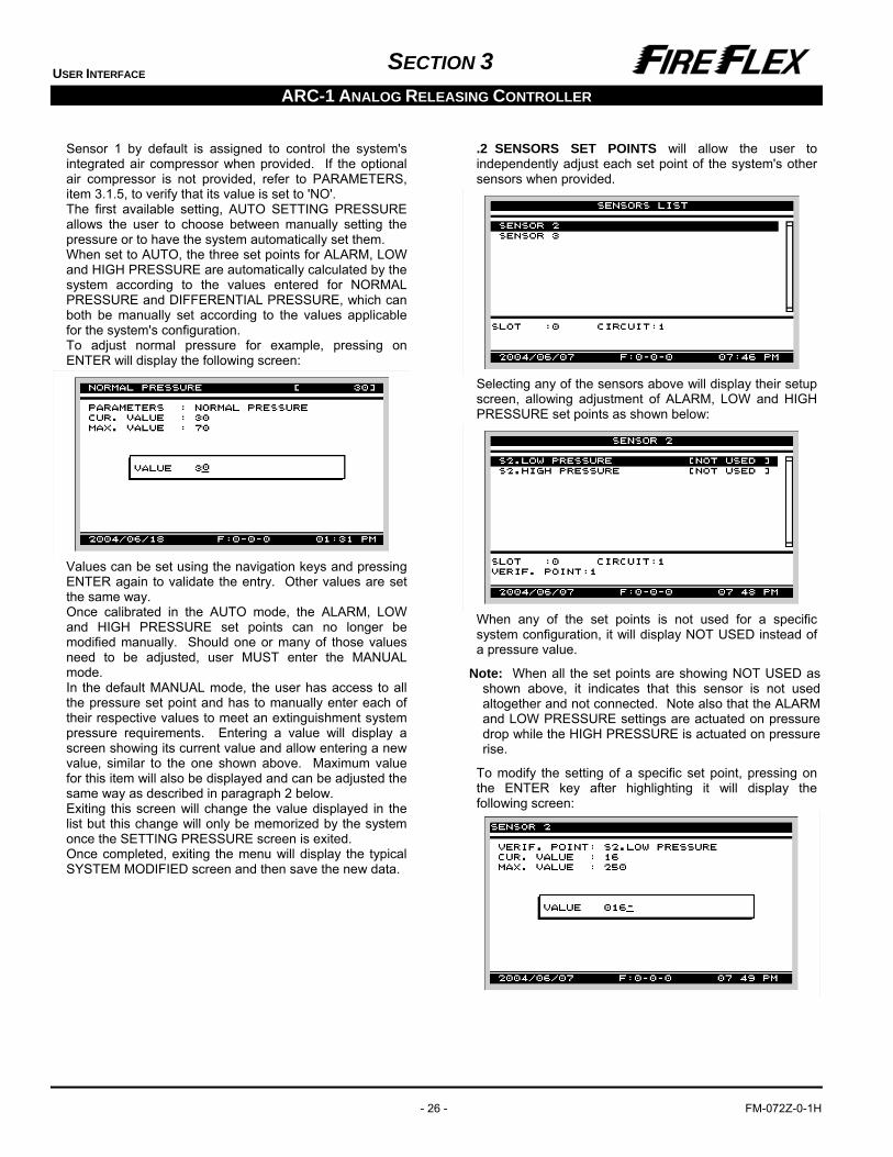
USER INTERFACE SECTION 3
ARC-1 ANALOG RELEASING CONTROLLER
- 26 - FM-072Z-0-1H
Sensor 1 by default is assigned to control the system's integrated air compressor when provided. If the optional air compressor is not provided, refer to PARAMETERS, item 3.1.5, to verify that its value is set to 'NO'. The first available setting, AUTO SETTING PRESSURE allows the user to choose between manually setting the pressure or to have the system automatically set them. When set to AUTO, the three set points for ALARM, LOW and HIGH PRESSURE are automatically calculated by the system according to the values entered for NORMAL PRESSURE and DIFFERENTIAL PRESSURE, which can both be manually set according to the values applicable for the system's configuration. To adjust normal pressure for example, pressing on ENTER will display the following screen:
Values can be set using the navigation keys and pressing ENTER again to validate the entry. Other values are set the same way. Once calibrated in the AUTO mode, the ALARM, LOW and HIGH PRESSURE set points can no longer be modified manually. Should one or many of those values need to be adjusted, user MUST enter the MANUAL mode. In the default MANUAL mode, the user has access to all the pressure set point and has to manually enter each of their respective values to meet an extinguishment system pressure requirements. Entering a value will display a screen showing its current value and allow entering a new value, similar to the one shown above. Maximum value for this item will also be displayed and can be adjusted the same way as described in paragraph 2 below. Exiting this screen will change the value displayed in the list but this change will only be memorized by the system once the SETTING PRESSURE screen is exited. Once completed, exiting the menu will display the typical SYSTEM MODIFIED screen and then save the new data.
.2 SENSORS SET POINTS will allow the user to independently adjust each set point of the system's other sensors when provided.
Selecting any of the sensors above will display their setup screen, allowing adjustment of ALARM, LOW and HIGH PRESSURE set points as shown below:
When any of the set points is not used for a specific system configuration, it will display NOT USED instead of a pressure value.
Note: When all the set points are showing NOT USED as shown above, it indicates that this sensor is not used altogether and not connected. Note also that the ALARM and LOW PRESSURE settings are actuated on pressure drop while the HIGH PRESSURE is actuated on pressure rise.
To modify the setting of a specific set point, pressing on the ENTER key after highlighting it will display the following screen:
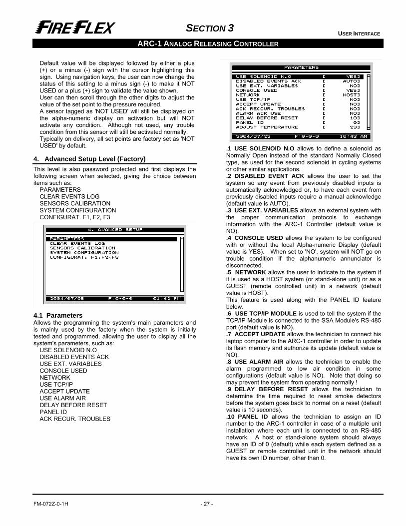
SECTION 3 USER INTERFACE ARC-1 ANALOG RELEASING CONTROLLER
FM-072Z-0-1H - 27 -
Default value will be displayed followed by either a plus (+) or a minus (-) sign with the cursor highlighting this sign. Using navigation keys, the user can now change the status of this setting to a minus sign (-) to make it NOT USED or a plus (+) sign to validate the value shown. User can then scroll through the other digits to adjust the value of the set point to the pressure required. A sensor tagged as 'NOT USED' will still be displayed on the alpha-numeric display on activation but will NOT activate any condition. Although not used, any trouble condition from this sensor will still be activated normally. Typically on delivery, all set points are factory set as 'NOT USED' by default.
4. Advanced Setup Level (Factory) This level is also password protected and first displays the following screen when selected, giving the choice between items such as:
PARAMETERS CLEAR EVENTS LOG SENSORS CALIBRATION SYSTEM CONFIGURATION CONFIGURAT. F1, F2, F3
4.1 Parameters Allows the programming the system's main parameters and is mainly used by the factory when the system is initially tested and programmed, allowing the user to display all the system's parameters, such as:
USE SOLENOID N.O DISABLED EVENTS ACK USE EXT. VARIABLES CONSOLE USED NETWORK USE TCP/IP ACCEPT UPDATE USE ALARM AIR DELAY BEFORE RESET PANEL ID ACK RECUR. TROUBLES
.1 USE SOLENOID N.O allows to define a solenoid as Normally Open instead of the standard Normally Closed type, as used for the second solenoid in cycling systems or other similar applications. .2 DISABLED EVENT ACK allows the user to set the system so any event from previously disabled inputs is automatically acknowledged or, to have each event from previously disabled inputs require a manual acknowledge (default value is AUTO). .3 USE EXT. VARIABLES allows an external system with the proper communication protocols to exchange information with the ARC-1 Controller (default value is NO). .4 CONSOLE USED allows the system to be configured with or without the local Alpha-numeric Display (default value is YES). When set to 'NO', system will NOT go on trouble condition if the alphanumeric annunciator is disconnected. .5 NETWORK allows the user to indicate to the system if it is used as a HOST system (or stand-alone unit) or as a GUEST (remote controlled unit) in a network (default value is HOST). This feature is used along with the PANEL ID feature below. .6 USE TCP/IP MODULE is used to tell the system if the TCP/IP Module is connected to the SSA Module's RS-485 port (default value is NO). .7 ACCEPT UPDATE allows the technician to connect his laptop computer to the ARC-1 controller in order to update its flash memory and authorize its update (default value is NO). .8 USE ALARM AIR allows the technician to enable the alarm programmed to low air condition in some configurations (default value is NO). Note that doing so may prevent the system from operating normally ! .9 DELAY BEFORE RESET allows the technician to determine the time required to reset smoke detectors before the system goes back to normal on a reset (default value is 10 seconds). .10 PANEL ID allows the technician to assign an ID number to the ARC-1 controller in case of a multiple unit installation where each unit is connected to an RS-485 network. A host or stand-alone system should always have an ID of 0 (default) while each system defined as a GUEST or remote controlled unit in the network should have its own ID number, other than 0.
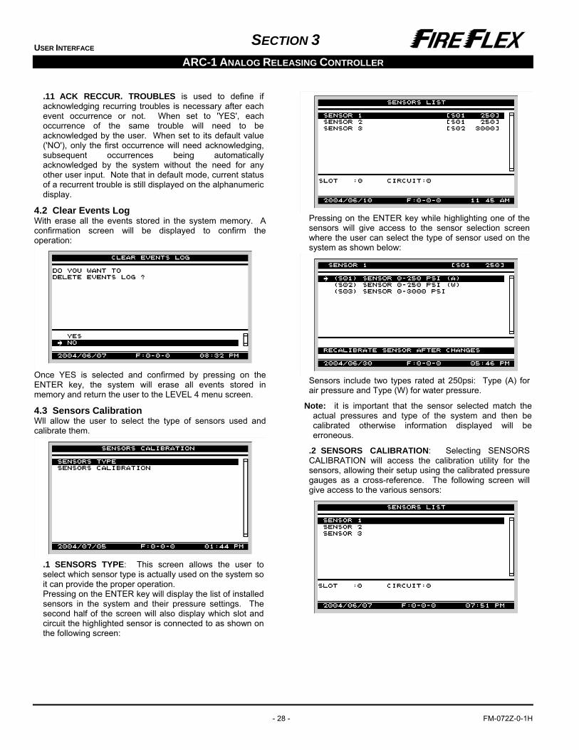
USER INTERFACE SECTION 3
ARC-1 ANALOG RELEASING CONTROLLER
- 28 - FM-072Z-0-1H
.11 ACK RECCUR. TROUBLES is used to define if acknowledging recurring troubles is necessary after each event occurrence or not. When set to 'YES', each occurrence of the same trouble will need to be acknowledged by the user. When set to its default value ('NO'), only the first occurrence will need acknowledging, subsequent occurrences being automatically acknowledged by the system without the need for any other user input. Note that in default mode, current status of a recurrent trouble is still displayed on the alphanumeric display.
4.2 Clear Events Log With erase all the events stored in the system memory. A confirmation screen will be displayed to confirm the operation:
Once YES is selected and confirmed by pressing on the ENTER key, the system will erase all events stored in memory and return the user to the LEVEL 4 menu screen.
4.3 Sensors Calibration Wll allow the user to select the type of sensors used and calibrate them.
.1 SENSORS TYPE: This screen allows the user to select which sensor type is actually used on the system so it can provide the proper operation. Pressing on the ENTER key will display the list of installed sensors in the system and their pressure settings. The second half of the screen will also display which slot and circuit the highlighted sensor is connected to as shown on the following screen:
Pressing on the ENTER key while highlighting one of the sensors will give access to the sensor selection screen where the user can select the type of sensor used on the system as shown below:
Sensors include two types rated at 250psi: Type (A) for air pressure and Type (W) for water pressure.
Note: it is important that the sensor selected match the actual pressures and type of the system and then be calibrated otherwise information displayed will be erroneous.
.2 SENSORS CALIBRATION: Selecting SENSORS CALIBRATION will access the calibration utility for the sensors, allowing their setup using the calibrated pressure gauges as a cross-reference. The following screen will give access to the various sensors:
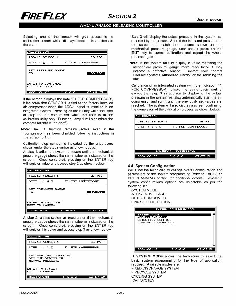
SECTION 3 USER INTERFACE ARC-1 ANALOG RELEASING CONTROLLER
FM-072Z-0-1H - 29 -
Selecting one of the sensor will give access to its calibration screen which displays detailed instructions to the user.
If the screen displays the note "F1 FOR COMPRESSOR", it indicates that SENSOR 1 is tied to the factory installed air compressor when the ARC-1 panel is installed in an integrated system. Pressing on the F1 key will either start or stop the air compressor while the user is in the calibration utility only. Function Lamp 1 will also mirror the compressor status (on or off).
Note: The F1 function remains active even if the compressor has been disabled following instructions is paragraph 3.1.5.
Calibration step number is indicated by the underscore shown under the step number as shown above. At step 1, adjust the system pressure until the mechanical pressure gauge shows the same value as indicated on the screen. Once completed, pressing on the ENTER key will register value and access step 2 as shown below:
At step 2, release system air pressure until the mechanical pressure gauge shows the same value as indicated on the screen. Once completed, pressing on the ENTER key will register this value and access step 3 as shown below.
Step 3 will display the actual pressure in the system, as detected by the sensor. Should the indicated pressure on the screen not match the pressure shown on the mechanical pressure gauge, user should press on the EXIT key to cancel calibration and repeat the whole process again.
Note: If the system fails to display a value matching the mechanical pressure gauge more than twice it may indicate a defective sensor. Contact your nearest FireFlex Systems Authorized Distributor for servicing the unit.
Calibration of an integrated system (with the indication F1 FOR COMPRESSOR) follows the same basic routine except that step 3 in addition to displaying the actual pressure in the system will also automatically start the air compressor and run it until the previously set values are reached. The system will also display a screen confirming the completion of the calibration process as shown below:
4.4 System Configuration Will allow the technician to change overall configuration and parameters of the system programming (refer to FACTORY PROGRAMMING section for additional details). Available system configurations options are selectable as per the following list:
SYSTEM MODE ADD/REMOVE CARD DETECTION CONFIG. LINK SLOT DETECTION
.1 SYSTEM MODE allows the technician to select the basic system programming for the type of application required. Available modes are: FIXED DISCHARGE SYSTEM FIRECYCLE SYSTEM CYCLING SYSTEM ICAF SYSTEM
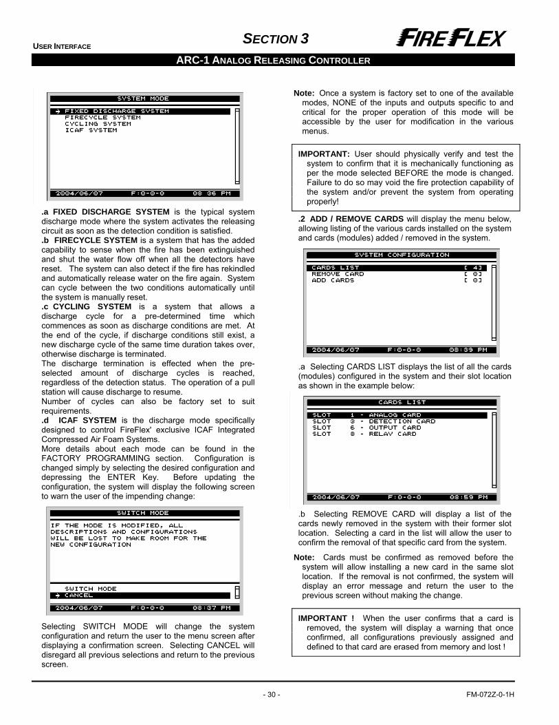
USER INTERFACE SECTION 3
ARC-1 ANALOG RELEASING CONTROLLER
- 30 - FM-072Z-0-1H
.a FIXED DISCHARGE SYSTEM is the typical system discharge mode where the system activates the releasing circuit as soon as the detection condition is satisfied. .b FIRECYCLE SYSTEM is a system that has the added capability to sense when the fire has been extinguished and shut the water flow off when all the detectors have reset. The system can also detect if the fire has rekindled and automatically release water on the fire again. System can cycle between the two conditions automatically until the system is manually reset. .c CYCLING SYSTEM is a system that allows a discharge cycle for a pre-determined time which commences as soon as discharge conditions are met. At the end of the cycle, if discharge conditions still exist, a new discharge cycle of the same time duration takes over, otherwise discharge is terminated. The discharge termination is effected when the pre-selected amount of discharge cycles is reached, regardless of the detection status. The operation of a pull station will cause discharge to resume. Number of cycles can also be factory set to suit requirements. .d ICAF SYSTEM is the discharge mode specifically designed to control FireFlex' exclusive ICAF Integrated Compressed Air Foam Systems. More details about each mode can be found in the FACTORY PROGRAMMING section. Configuration is changed simply by selecting the desired configuration and depressing the ENTER Key. Before updating the configuration, the system will display the following screen to warn the user of the impending change:
Selecting SWITCH MODE will change the system configuration and return the user to the menu screen after displaying a confirmation screen. Selecting CANCEL will disregard all previous selections and return to the previous screen.
Note: Once a system is factory set to one of the available modes, NONE of the inputs and outputs specific to and critical for the proper operation of this mode will be accessible by the user for modification in the various menus.
IMPORTANT: User should physically verify and test the system to confirm that it is mechanically functioning as per the mode selected BEFORE the mode is changed. Failure to do so may void the fire protection capability of the system and/or prevent the system from operating properly!
.2 ADD / REMOVE CARDS will display the menu below, allowing listing of the various cards installed on the system and cards (modules) added / removed in the system.
.a Selecting CARDS LIST displays the list of all the cards (modules) configured in the system and their slot location as shown in the example below:
.b Selecting REMOVE CARD will display a list of the cards newly removed in the system with their former slot location. Selecting a card in the list will allow the user to confirm the removal of that specific card from the system.
Note: Cards must be confirmed as removed before the system will allow installing a new card in the same slot location. If the removal is not confirmed, the system will display an error message and return the user to the previous screen without making the change.
IMPORTANT ! When the user confirms that a card is removed, the system will display a warning that once confirmed, all configurations previously assigned and defined to that card are erased from memory and lost !
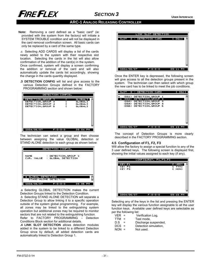
SECTION 3 USER INTERFACE ARC-1 ANALOG RELEASING CONTROLLER
FM-072Z-0-1H - 31 -
Note: Removing a card defined as a "basic card" (ie: provided with the system from the factory) will initiate a SYSTEM TROUBLE condition and will not be displayed in the card removal confirmation screen. All basic cards can only be replaced by a card of the same type.
.c Selecting ADD CARDS will display a list of the cards newly added to the system with their respective slot location. Selecting the cards in the list will also allow confirmation of the addition of the card(s) in the system. Once confirmed, system will display a screen confirming the addition or removal of the card and will also automatically update the cards list accordingly, showing the change in the cards quantity displayed.
.3 DETECTION CONFIG will list and give access to the various Detection Groups defined in the FACTORY PROGRAMMING section and shown below:
The technician can select a group and then choose between assigning the value GLOBAL detection or STAND ALONE detection to each group as shown below:
.a Selecting GLOBAL DETECTION makes the current Detection Groups linked to the Detection Condition. .b Selecting STAND ALONE DETECTION will separate a Detection Group to allow linking it to a specific operation outside of the system global programming. For example, all zones may be linked to the extinguishing system operation but additional zones may be required to monitor sectors that are not related to the extinguishing function. Refer to FACTORY PROGRAMMING – Detection Conditions Block section for additional details. .4 LINK SLOT DETECTION allows detection modules added in the system to be linked to a different Detection Group since by default, all added detection cards are automatically linked to Detection Group 1.
Once the ENTER key is depressed, the following screen will give access to all the detection groups present in the system. The technician can then select with which group the new card has to be linked to meet the job conditions.
The concept of Detection Groups is more clearly described in the FACTORY PROGRAMMING section.
4.5 Configuration of F1, F2, F3 Will allow the factory to assign a special function to any of the 3 user defined keys. The following screen is displayed first, showing the initial values assigned to each key (if any).
Selecting any of the keys in the list and pressing the ENTER key will display the various function assignable to all the user function keys. Available user defined keys are selectable as per the following list:
VER = Verification Log, TTM = Test mode, D.S = Discharge suspended, DCS = Detection simulation, NON = Not used.
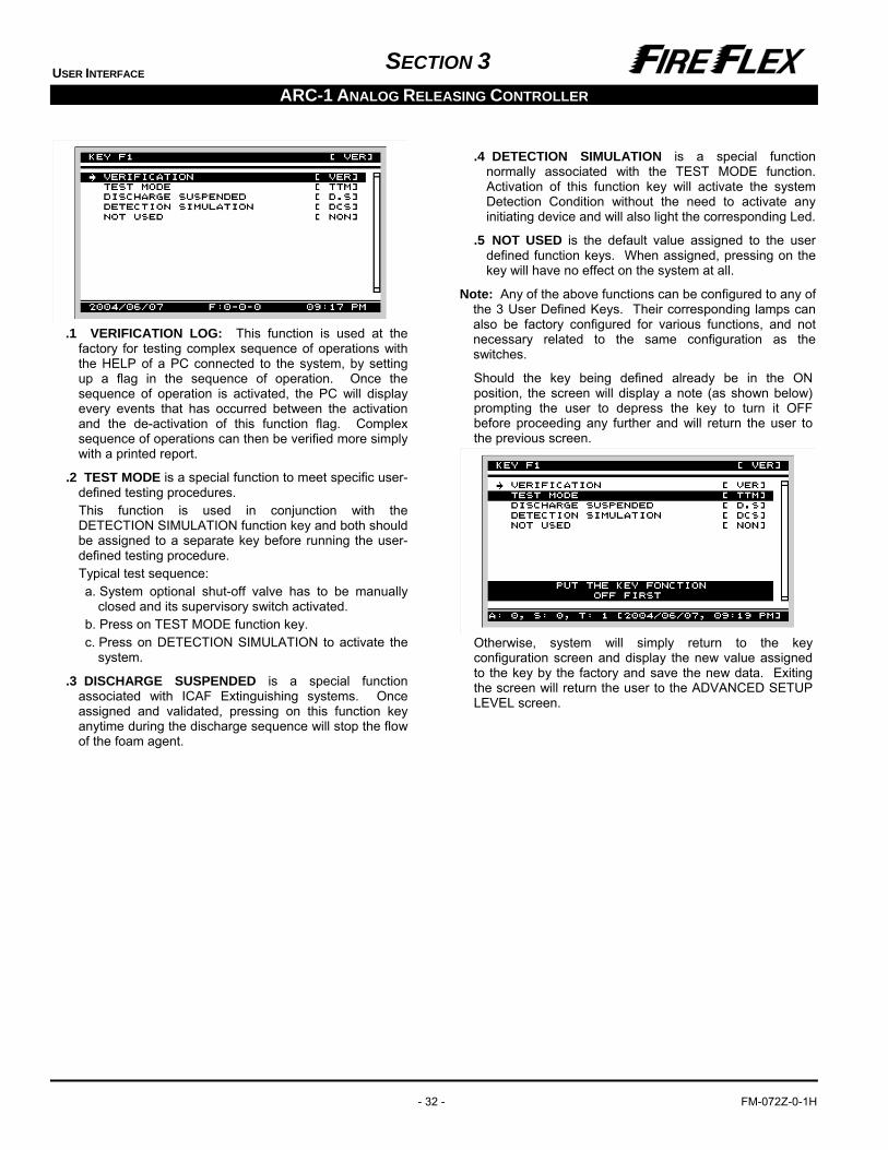
USER INTERFACE SECTION 3
ARC-1 ANALOG RELEASING CONTROLLER
- 32 - FM-072Z-0-1H
.1 VERIFICATION LOG: This function is used at the
factory for testing complex sequence of operations with the HELP of a PC connected to the system, by setting up a flag in the sequence of operation. Once the sequence of operation is activated, the PC will display every events that has occurred between the activation and the de-activation of this function flag. Complex sequence of operations can then be verified more simply with a printed report.
.2 TEST MODE is a special function to meet specific user-defined testing procedures. This function is used in conjunction with the DETECTION SIMULATION function key and both should be assigned to a separate key before running the user-defined testing procedure. Typical test sequence: a. System optional shut-off valve has to be manually
closed and its supervisory switch activated. b. Press on TEST MODE function key. c. Press on DETECTION SIMULATION to activate the
system.
.3 DISCHARGE SUSPENDED is a special function associated with ICAF Extinguishing systems. Once assigned and validated, pressing on this function key anytime during the discharge sequence will stop the flow of the foam agent.
.4 DETECTION SIMULATION is a special function normally associated with the TEST MODE function. Activation of this function key will activate the system Detection Condition without the need to activate any initiating device and will also light the corresponding Led.
.5 NOT USED is the default value assigned to the user defined function keys. When assigned, pressing on the key will have no effect on the system at all.
Note: Any of the above functions can be configured to any of the 3 User Defined Keys. Their corresponding lamps can also be factory configured for various functions, and not necessary related to the same configuration as the switches.
Should the key being defined already be in the ON position, the screen will display a note (as shown below) prompting the user to depress the key to turn it OFF before proceeding any further and will return the user to the previous screen.
Otherwise, system will simply return to the key configuration screen and display the new value assigned to the key by the factory and save the new data. Exiting the screen will return the user to the ADVANCED SETUP LEVEL screen.
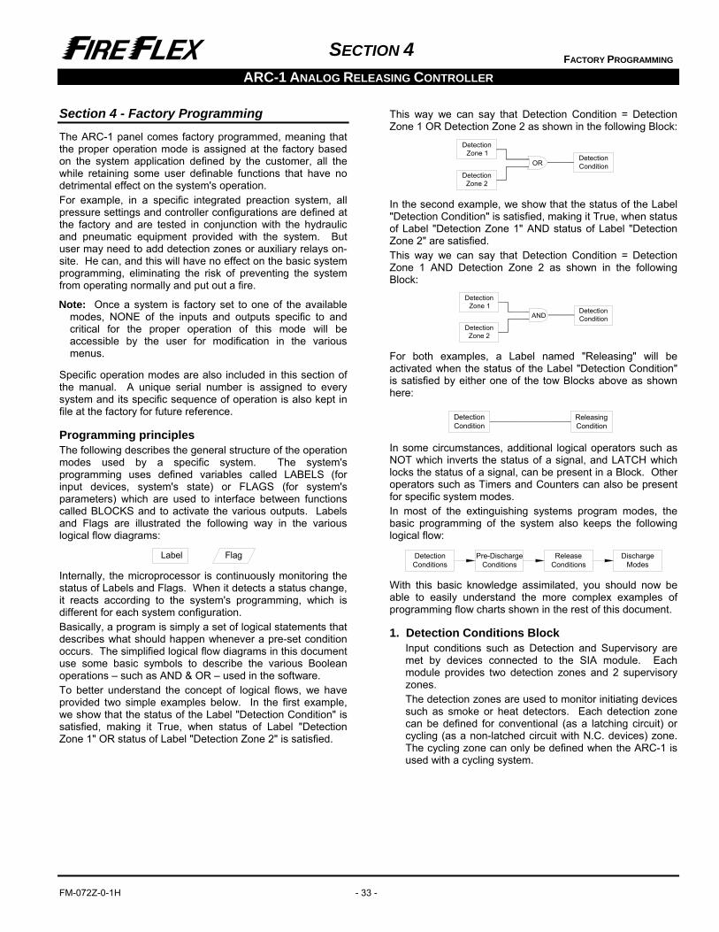
SECTION 4 FACTORY PROGRAMMING ARC-1 ANALOG RELEASING CONTROLLER
FM-072Z-0-1H - 33 -
Section 4 - Factory Programming
The ARC-1 panel comes factory programmed, meaning that the proper operation mode is assigned at the factory based on the system application defined by the customer, all the while retaining some user definable functions that have no detrimental effect on the system's operation. For example, in a specific integrated preaction system, all pressure settings and controller configurations are defined at the factory and are tested in conjunction with the hydraulic and pneumatic equipment provided with the system. But user may need to add detection zones or auxiliary relays on-site. He can, and this will have no effect on the basic system programming, eliminating the risk of preventing the system from operating normally and put out a fire.
Note: Once a system is factory set to one of the available modes, NONE of the inputs and outputs specific to and critical for the proper operation of this mode will be accessible by the user for modification in the various menus.
Specific operation modes are also included in this section of the manual. A unique serial number is assigned to every system and its specific sequence of operation is also kept in file at the factory for future reference.
Programming principles The following describes the general structure of the operation modes used by a specific system. The system's programming uses defined variables called LABELS (for input devices, system's state) or FLAGS (for system's parameters) which are used to interface between functions called BLOCKS and to activate the various outputs. Labels and Flags are illustrated the following way in the various logical flow diagrams:
Label Flag
Internally, the microprocessor is continuously monitoring the status of Labels and Flags. When it detects a status change, it reacts according to the system's programming, which is different for each system configuration. Basically, a program is simply a set of logical statements that describes what should happen whenever a pre-set condition occurs. The simplified logical flow diagrams in this document use some basic symbols to describe the various Boolean operations – such as AND & OR – used in the software. To better understand the concept of logical flows, we have provided two simple examples below. In the first example, we show that the status of the Label "Detection Condition" is satisfied, making it True, when status of Label "Detection Zone 1" OR status of Label "Detection Zone 2" is satisfied.
This way we can say that Detection Condition = Detection Zone 1 OR Detection Zone 2 as shown in the following Block:
DetectionZone 2
DetectionZone 1
ORDetectionCondition
In the second example, we show that the status of the Label "Detection Condition" is satisfied, making it True, when status of Label "Detection Zone 1" AND status of Label "Detection Zone 2" are satisfied. This way we can say that Detection Condition = Detection Zone 1 AND Detection Zone 2 as shown in the following Block:
DetectionZone 1
DetectionZone 2
DetectionConditionAND
For both examples, a Label named "Releasing" will be activated when the status of the Label "Detection Condition" is satisfied by either one of the tow Blocks above as shown here:
DetectionCondition
ReleasingCondition
In some circumstances, additional logical operators such as NOT which inverts the status of a signal, and LATCH which locks the status of a signal, can be present in a Block. Other operators such as Timers and Counters can also be present for specific system modes. In most of the extinguishing systems program modes, the basic programming of the system also keeps the following logical flow:
DetectionConditions
Pre-DischargeConditions
ReleaseConditions
DischargeModes
With this basic knowledge assimilated, you should now be able to easily understand the more complex examples of programming flow charts shown in the rest of this document.
1. Detection Conditions Block Input conditions such as Detection and Supervisory are met by devices connected to the SIA module. Each module provides two detection zones and 2 supervisory zones. The detection zones are used to monitor initiating devices such as smoke or heat detectors. Each detection zone can be defined for conventional (as a latching circuit) or cycling (as a non-latched circuit with N.C. devices) zone. The cycling zone can only be defined when the ARC-1 is used with a cycling system.

FACTORY PROGRAMMING SECTION 4
ARC-1 ANALOG RELEASING CONTROLLER
- 34 - FM-072Z-0-1H
The supervisory zones can be used to monitor listed dry contact devices such as manual pull stations, abort, pressure, and tamper switches, etc. A label is defined for each type of device; the status of a device becomes 'True' upon its activation.
Slot ID
Zone 1 Non-Latching N.C.
CONVENTIONAL ZONE
FIRECYCLE ZONE
Zone 2Latching N.O.
Detection Groups: For each SIA module present in the system, detection zones are always combined in pairs, forming a Detection Group. Up to 5 Detection Groups can be assigned in a system (two groups for two modules, three for three modules, etc., up to the allowable total of five), each one defined by its own Label (Detection Group 1 to 5). Each Detection Group possesses its own cross-zoning configuration. Then, if the Cross Zone Flag for Detection Group 1 is set to False, the activation logic for Detection Group 1 according to Zones 1 and 2 of Input Module 3 will be: Detection Group1 = InputModule3.Zone1 OR InputModule3.Zone2. If the Cross Zone Flag is set to True, the activation logic will be changed over to: Detection Group1 = InputModule3.Zone1 AND InputModule3.Zone2.
Latch Info.Contact Type
Slot ID
Latch Info.Contact Type
ANDOR
OR
ANDAND
X_ZoneGroup ID
DetectionGroup ID
NOT
Pre-defined Detection Condition: The Detection Condition will be satisfied when any of the Detection Group conditions is satisfied. The activation logic of this function will be: Detection Condition = Detection Group1 OR Detection Group2 OR Detection Group3 OR Detection Group4 OR Detection Group5.
DetectionGroup 1
DetectionGroup 2
ORDetectionCondition
DetectionGroup 4
DetectionGroup 3
DetectionGroup 5
Additional Detection Group: An Additional Detection Group is created by adding an SIA module to the system. By default, each new SIA module added to the system is labeled Detection Group1. Note here that the same Detection Group number can be assigned to more than one module. When using that particular mode, it's the same as if both zones 1 of each module are connected together to the same Detection Group (same thing for both zones 2). This is the same as doubling the total quantity of smoke detectors that can be connected on the detection zone. In this mode, cross zoning will work as well. The Detection Group of the added module can also be assigned to a different Detection Group. In the case of a preaction system protecting two separate areas, the user might want to operate visual devices such as strobe lights to indicate which area is in alarm. The Detection Group1 could then be assigned to activate a relay or a supervised output circuit for signaling devices in area 1, and Detection Group2 could be assigned to activate a relay or a supervised output circuit for signaling devices in area 2. The Detection Condition which is satisfied by either one of these two conditions can then be used for the release condition. Cross-zoning: Additionally, a Detection Group can also be used in a stand-alone mode. In this particular mode – limited to Detection Groups 2 to 5 –the user is allowed to add supplementary detection zones that will not activate the Detection Condition and work independently (detection only). Using this mode, both zones of the added module are then stand-alone.
2. Pre-discharge Conditions Block This block includes special functions that are intended to be used for special applications only and must be approved by the local AHJ prior to their use. Pre-Discharge Condition is primarily triggered by Detection Condition. This signal might be on hold for the duration of an optional delay according to the pre-discharge timer. Other conditions may prevent the Pre-Discharge Condition from happening.
NOT
Latch
ShutdownBypass Timer
0 - 1 min. 45 sec.
DetectionCondition
Pre-Discharge Delay
Abort Station
AND
ShutdownConfirmation
OR
ANDPre-Discharge
Condition
An Abort Station, when used, can prevent the Pre-discharge Condition to happen as long as it is maintained activated. A Shutdown Confirmation function may also be used to prevent the Pre-Discharge Condition. This signal comes from equipment to which a Shutdown Request signal has previously been sent; logic is shown below. This function is available for applications where water discharging prior

SECTION 4 FACTORY PROGRAMMING ARC-1 ANALOG RELEASING CONTROLLER
FM-072Z-0-1H - 35 -
to electrical shutdown would have adverse effects on the protected equipment or cause personnel injuries. A Shutdown Bypass Timer is used along this function to override the Shutdown Confirmation after a specific time period in case it is never received. Another example of this use would be in elevator protection where a failsafe timer is provided to bypass the elevator recall confirmation contact in case the elevator car never reaches its recall lobby.
DetectionCondition
ReleaseCondition
WaterflowDischarge
ORShutdown RequestLatch
The Pre-discharge Condition is latched until system is manually reset.
3. Release Conditions Block The Release Condition Block includes all the required conditions prior to initiate the system release. The Release Condition is latched until the system is manually reset. Release Condition is primarily intended to be triggered by Pre-Discharge Condition. A Manual Pull Station, when connected to a supervisory zone and defined as such, will also directly trigger the Release Condition. The Alarm Air Not Used Flag, when True, will bypass the Very Low Pressure, allowing a Release Condition by a satisfied Pre-Discharge Condition. When False, Pre-Discharge Condition AND Very Low Pressure will have to be satisfied in order to have a Release Condition. This function is typically used for double interlock preaction systems. In this configuration, both the Detection Condition and the Open Sprinkler Head must occur prior to system activation.
Pre-Discharge Conditions
UseAlarm Air
NOT
ManualPull Station
Very LowPressure OR
Latch ReleaseConditionOR
AND
4. Discharge Modes Block The System Release is normally assigned to a Solenoid Valve which controls the automatic system discharge. .1 Fixed discharge mode: In this mode, the System
Release is directly activated by a satisfied Release Condition. The System Release is latched until system is manually reset.
ReleaseCondition
SystemRelease
.2 Firecycle discharge mode: In this mode, the System
Release is activated by the Release Condition and Detection Condition. This condition prevails as long as the Detection Condition is present. When Detection Condition disappears, discharge stops at the end of a defined timer cycle. At least one Cycling Detection Zone must be configured for this mode in the Detection Condition, and it must also use Firecycle detectors.
NOT
AND SystemRelease
AND
5 min. - 10 min.
Release Condition
Detection Condition
Release Condition
Detection Condition
OR
ManualPull Station
Soak-Timer
DetectionCondition
Run
Start
Reset
The System Release is initially activated by a Release Condition. Since Release Condition requires a Detection Condition, both conditions are satisfied for initial discharge. When all the Firecycle detectors cool down below their trip point, making the Detection Condition False, a defined Soak-Timer is now available and starts, maintaining the System Release set to True until it expires, at which point System Release Condition is switched back to False, stopping the discharge. Should the Detection Condition reappear, the Soak-Timer is reset and the above sequence is repeated. The Soak-Timer is a defined type of Label with its Run output becoming True when a True condition appears at its Start input. It runs until timer expires, at which point the Run output is changed to False. The Reset input resets the Run output no matter what the condition of the Start input is. All signals are Normally False upon activation. A Manual Pull Station, when connected to a supervisory zone and defined as such, will directly trigger the Release Condition and latch it until the system is manually reset.
.3 Cycling Mode: In this mode, the System Release is activated by the Release Condition and the Detection Condition. This condition allows a timer to start a cycle of a defined duration then stop discharge once the timer expires; should the Detection Condition still be present at the end of the timer cycle, a new discharge cycle will start. A cycle counter can limit the number of discharge cycles required, which will totally disable the System Release once its value is reached. At least one
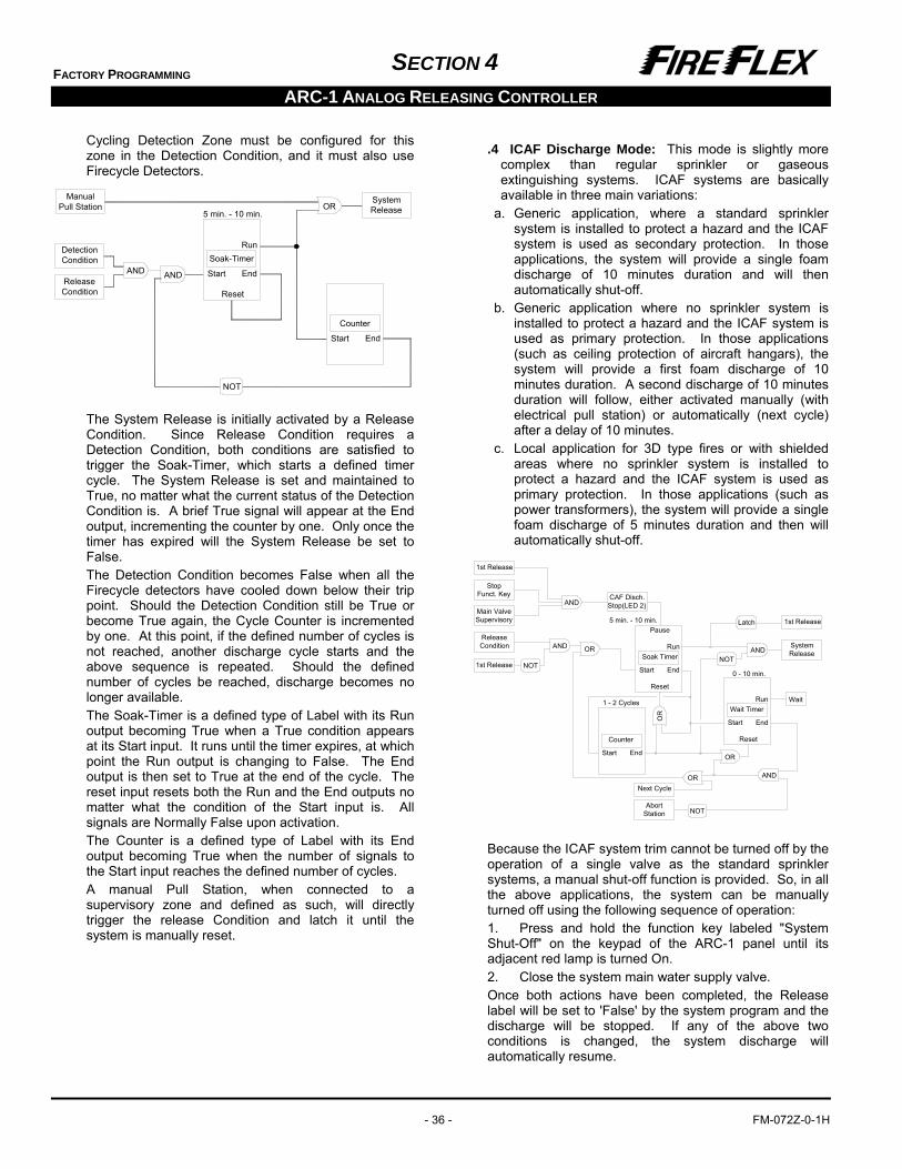
FACTORY PROGRAMMING SECTION 4
ARC-1 ANALOG RELEASING CONTROLLER
- 36 - FM-072Z-0-1H
Cycling Detection Zone must be configured for this zone in the Detection Condition, and it must also use Firecycle Detectors.
SystemRelease
AND
NOT
5 min. - 10 min.
Detection Condition
Release Condition Reset
Soak-Timer
Start End
Run
ManualPull Station OR
AND
Counter
Start End
The System Release is initially activated by a Release Condition. Since Release Condition requires a Detection Condition, both conditions are satisfied to trigger the Soak-Timer, which starts a defined timer cycle. The System Release is set and maintained to True, no matter what the current status of the Detection Condition is. A brief True signal will appear at the End output, incrementing the counter by one. Only once the timer has expired will the System Release be set to False. The Detection Condition becomes False when all the Firecycle detectors have cooled down below their trip point. Should the Detection Condition still be True or become True again, the Cycle Counter is incremented by one. At this point, if the defined number of cycles is not reached, another discharge cycle starts and the above sequence is repeated. Should the defined number of cycles be reached, discharge becomes no longer available. The Soak-Timer is a defined type of Label with its Run output becoming True when a True condition appears at its Start input. It runs until the timer expires, at which point the Run output is changing to False. The End output is then set to True at the end of the cycle. The reset input resets both the Run and the End outputs no matter what the condition of the Start input is. All signals are Normally False upon activation. The Counter is a defined type of Label with its End output becoming True when the number of signals to the Start input reaches the defined number of cycles. A manual Pull Station, when connected to a supervisory zone and defined as such, will directly trigger the release Condition and latch it until the system is manually reset.
.4 ICAF Discharge Mode: This mode is slightly more complex than regular sprinkler or gaseous extinguishing systems. ICAF systems are basically available in three main variations:
a. Generic application, where a standard sprinkler system is installed to protect a hazard and the ICAF system is used as secondary protection. In those applications, the system will provide a single foam discharge of 10 minutes duration and will then automatically shut-off.
b. Generic application where no sprinkler system is installed to protect a hazard and the ICAF system is used as primary protection. In those applications (such as ceiling protection of aircraft hangars), the system will provide a first foam discharge of 10 minutes duration. A second discharge of 10 minutes duration will follow, either activated manually (with electrical pull station) or automatically (next cycle) after a delay of 10 minutes.
c. Local application for 3D type fires or with shielded areas where no sprinkler system is installed to protect a hazard and the ICAF system is used as primary protection. In those applications (such as power transformers), the system will provide a single foam discharge of 5 minutes duration and then will automatically shut-off.
End
Reset
Soak TimerRun
5 min. - 10 min.
CAF Disch.Stop(LED 2)
Pause
NOT
0 - 10 min.
Run
AND
Latch
Wait
SystemRelease
1st Release
1st Release
1st Release
StopFunct. Key
Main ValveSupervisory
Release Condition
NOT
AND
AND
1 - 2 CyclesWait Timer
AbortStation
Next Cycle
Counter
EndStart
OR
AND
NOT
OR
OR
Start
Reset
End
OR
Start
Because the ICAF system trim cannot be turned off by the operation of a single valve as the standard sprinkler systems, a manual shut-off function is provided. So, in all the above applications, the system can be manually turned off using the following sequence of operation: 1. Press and hold the function key labeled "System Shut-Off" on the keypad of the ARC-1 panel until its adjacent red lamp is turned On. 2. Close the system main water supply valve. Once both actions have been completed, the Release label will be set to 'False' by the system program and the discharge will be stopped. If any of the above two conditions is changed, the system discharge will automatically resume.

SECTION 4 FACTORY PROGRAMMING ARC-1 ANALOG RELEASING CONTROLLER
FM-072Z-0-1H - 37 -
5. Special functions .1 N.O. Solenoid / Vent function: With Firecycle and
cycling systems, a normally open (N.O.) solenoid valve is used as a fail-safe feature in the trim. The following function is used to control its proper operation:
Waterflow /Discharge
ANDSolenoid
N.O. / VentNOT
Release Condition
OR
LowPressure
That same function is used for the vent solenoid used with ICAF systems using the fail-safe electrical release operation.
.2 Test Mode function: This function allows testing of various conditions on the system simply by pressing on the keypad's assigned key. The key press is detected by the system and activates the programmed function as described in the diagram below:
Test ModeFunct. Key
Test ModeActivated
DetectionSimul. key
Shut-OffValve Sup'v
AND
AND
DetectionCondition(LED 3)
Test ModeActivated(LED 2)
.3 Dry Contact Supervisory Circuits Special
Assignation: The dry contacts supervisory circuits in the system can be assigned to special functions as listed below, their indication and status when activated: - Manual pull station (Alarm condition – Latching). - Alarm Air (Supervisory condition – Latching). - Discharge Abort (Supervisory condition – Non-latching). - Shutdown Confirmation (Supervisory condition – Latching).
- Main Valve (Supervisory condition – Non-latching). - Shut-off Valve (Supervisory condition – Non-latching). - Water Flow (Alarm condition – Latching). - Supervisory (Supervisory condition – Latching).
6. Operation Modes Rules The following rules apply when creating a specific operation mode:
Alarm Status: - Alarm Latching N.O.: For normally open contact
devices or smoke detectors going in alarm condition. - Alarm Non-latching N.O.: For normally open contact
devices, closing in alarm condition, used for special applications only. Must be approved by the local AHJ.
- Alarm Non-latching N.C.: For normally closed contact devices, opening in alarm condition, as used by Firecycle type heat detectors on cycling systems.
- Water Flow / Discharge Latching N.O.: For discharge confirmation devices such as alarm pressure switches.
Supervisory Status: - Supervisory Latching N.O.: For normally open
contact devices that close upon a supervisory condition.
- Supervisory Non-latching N.O.: For normally open contact devices that close upon a supervisory condition.
- Supervisory Non-latching N.C.: For normally closed contact devices that open upon a supervisory condition (ex.: Electrical shutdown confirmation).
Special Functions: Four (4) timers, two (2) cycling timers and four (4) counters are available for specific operation modes. The output circuits and the auxiliary relays associated with the basic operation of the system are all pre-programmed at the factory. Spare output circuits or auxiliary relays can be defined by the user on-site using a pre-defined selection list. PC Interface: A PC Interface and an accessory device can be provided for maintenance purpose or for printing reports.

FACTORY PROGRAMMING SECTION 4
ARC-1 ANALOG RELEASING CONTROLLER
- 38 - FM-072Z-0-1H
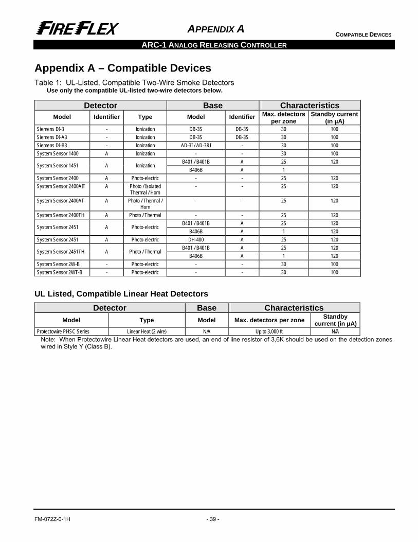
APPENDIX A COMPATIBLE DEVICES ARC-1 ANALOG RELEASING CONTROLLER
FM-072Z-0-1H - 39 -
Appendix A – Compatible Devices Table 1: UL-Listed, Compatible Two-Wire Smoke Detectors
Use only the compatible UL-listed two-wire detectors below.
Detector Base Characteristics Model Identifier Type Model Identifier Max. detectors
per zone Standby current
(in µA) Siemens DI-3 - Ionization DB-3S DB-3S 30 100 Siemens DI-A3 - Ionization DB-3S DB-3S 30 100 Siemens DI-B3 - Ionization AD-3I / AD-3RI - 30 100 System Sensor 1400 A Ionization - - 30 100
B401 / B401B A 25 120 System Sensor 1451 A Ionization
B406B A 1 System Sensor 2400 A Photo-electric - - 25 120 System Sensor 2400AIT A Photo / Isolated
Thermal / Horn - - 25 120
System Sensor 2400AT A Photo / Thermal / Horn
- - 25 120
System Sensor 2400TH A Photo / Thermal - - 25 120 B401 / B401B A 25 120
System Sensor 2451 A Photo-electric B406B A 1 120
System Sensor 2451 A Photo-electric DH-400 A 25 120 B401 / B401B A 25 120
System Sensor 2451TH A Photo / Thermal B406B A 1 120
System Sensor 2W-B - Photo-electric - - 30 100 System Sensor 2WT-B - Photo-electric - - 30 100
UL Listed, Compatible Linear Heat Detectors Detector Base Characteristics
Model Type Model Max. detectors per zone Standby current (in µA)
Protectowire PHSC Series Linear Heat (2 wire) N/A Up to 3,000 ft. N/A Note: When Protectowire Linear Heat detectors are used, an end of line resistor of 3,6K should be used on the detection zones wired in Style Y (Class B).
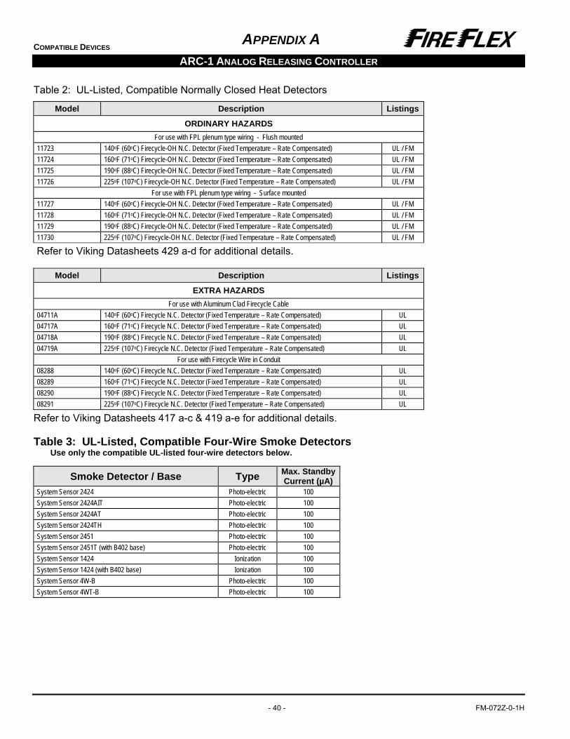
COMPATIBLE DEVICES APPENDIX A
ARC-1 ANALOG RELEASING CONTROLLER
- 40 - FM-072Z-0-1H
Table 2: UL-Listed, Compatible Normally Closed Heat Detectors
Model Description Listings
ORDINARY HAZARDS
For use with FPL plenum type wiring - Flush mounted 11723 140oF (60oC) Firecycle-OH N.C. Detector (Fixed Temperature – Rate Compensated) UL / FM 11724 160oF (71oC) Firecycle-OH N.C. Detector (Fixed Temperature – Rate Compensated) UL / FM 11725 190oF (88oC) Firecycle-OH N.C. Detector (Fixed Temperature – Rate Compensated) UL / FM 11726 225oF (107oC) Firecycle-OH N.C. Detector (Fixed Temperature – Rate Compensated) UL / FM
For use with FPL plenum type wiring - Surface mounted 11727 140oF (60oC) Firecycle-OH N.C. Detector (Fixed Temperature – Rate Compensated) UL / FM 11728 160oF (71oC) Firecycle-OH N.C. Detector (Fixed Temperature – Rate Compensated) UL / FM 11729 190oF (88oC) Firecycle-OH N.C. Detector (Fixed Temperature – Rate Compensated) UL / FM 11730 225oF (107oC) Firecycle-OH N.C. Detector (Fixed Temperature – Rate Compensated) UL / FM
Refer to Viking Datasheets 429 a-d for additional details.
Model Description Listings
EXTRA HAZARDS
For use with Aluminum Clad Firecycle Cable 04711A 140oF (60oC) Firecycle N.C. Detector (Fixed Temperature – Rate Compensated) UL 04717A 160oF (71oC) Firecycle N.C. Detector (Fixed Temperature – Rate Compensated) UL 04718A 190oF (88oC) Firecycle N.C. Detector (Fixed Temperature – Rate Compensated) UL 04719A 225oF (107oC) Firecycle N.C. Detector (Fixed Temperature – Rate Compensated) UL
For use with Firecycle Wire in Conduit 08288 140oF (60oC) Firecycle N.C. Detector (Fixed Temperature – Rate Compensated) UL 08289 160oF (71oC) Firecycle N.C. Detector (Fixed Temperature – Rate Compensated) UL 08290 190oF (88oC) Firecycle N.C. Detector (Fixed Temperature – Rate Compensated) UL 08291 225oF (107oC) Firecycle N.C. Detector (Fixed Temperature – Rate Compensated) UL
Refer to Viking Datasheets 417 a-c & 419 a-e for additional details.
Table 3: UL-Listed, Compatible Four-Wire Smoke Detectors Use only the compatible UL-listed four-wire detectors below.
Smoke Detector / Base Type Max. Standby Current (µA)
System Sensor 2424 Photo-electric 100 System Sensor 2424AIT Photo-electric 100 System Sensor 2424AT Photo-electric 100 System Sensor 2424TH Photo-electric 100 System Sensor 2451 Photo-electric 100 System Sensor 2451T (with B402 base) Photo-electric 100 System Sensor 1424 Ionization 100 System Sensor 1424 (with B402 base) Ionization 100 System Sensor 4W-B Photo-electric 100 System Sensor 4WT-B Photo-electric 100
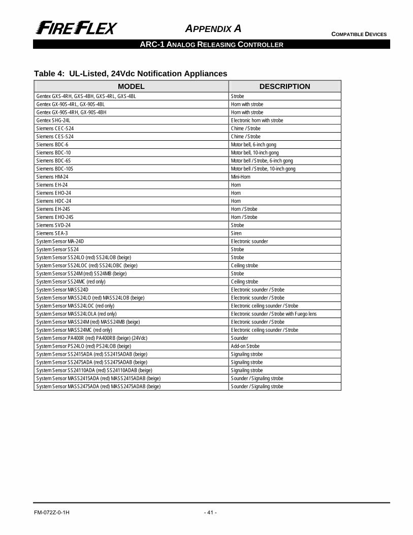
APPENDIX A COMPATIBLE DEVICES ARC-1 ANALOG RELEASING CONTROLLER
FM-072Z-0-1H - 41 -
Table 4: UL-Listed, 24Vdc Notification Appliances MODEL DESCRIPTION
Gentex GXS-4RH, GXS-4BH, GXS-4RL, GXS-4BL Strobe Gentex GX-90S-4RL, GX-90S-4BL Horn with strobe Gentex GX-90S-4RH, GX-90S-4BH Horn with strobe Gentex SHG-24L Electronic horn with strobe Siemens CEC-S24 Chime / Strobe Siemens CES-S24 Chime / Strobe Siemens BDC-6 Motor bell, 6-inch gong Siemens BDC-10 Motor bell, 10-inch gong Siemens BDC-6S Motor bell / Strobe, 6-inch gong Siemens BDC-10S Motor bell / Strobe, 10-inch gong Siemens HM-24 Mini-Horn Siemens EH-24 Horn Siemens EHO-24 Horn Siemens HDC-24 Horn Siemens EH-24S Horn / Strobe Siemens EHO-24S Horn / Strobe Siemens SVD-24 Strobe Siemens SEA-3 Siren System Sensor MA-24D Electronic sounder System Sensor SS24 Strobe System Sensor SS24LO (red) SS24LOB (beige) Strobe System Sensor SS24LOC (red) SS24LOBC (beige) Ceiling strobe System Sensor SS24M (red) SS24MB (beige) Strobe System Sensor SS24MC (red only) Ceiling strobe System Sensor MASS24D Electronic sounder / Strobe System Sensor MASS24LO (red) MASS24LOB (beige) Electronic sounder / Strobe System Sensor MASS24LOC (red only) Electronic ceiling sounder / Strobe System Sensor MASS24LOLA (red only) Electronic sounder / Strobe with Fuego lens System Sensor MASS24M (red) MASS24MB (beige) Electronic sounder / Strobe System Sensor MASS24MC (red only) Electronic ceiling sounder / Strobe System Sensor PA400R (red) PA400RB (beige) (24Vdc) Sounder System Sensor PS24LO (red) PS24LOB (beige) Add-on Strobe System Sensor SS2415ADA (red) SS2415ADAB (beige) Signaling strobe System Sensor SS2475ADA (red) SS2475ADAB (beige) Signaling strobe System Sensor SS24110ADA (red) SS24110ADAB (beige) Signaling strobe System Sensor MASS2415ADA (red) MASS2415ADAB (beige) Sounder / Signaling strobe System Sensor MASS2475ADA (red) MASS2475ADAB (beige) Sounder / Signaling strobe

COMPATIBLE DEVICES APPENDIX A
ARC-1 ANALOG RELEASING CONTROLLER
- 42 - FM-072Z-0-1H
Table 4: UL-Listed, 24Vdc Notification Appliances (continued) MODEL DESCRIPTION
System Sensor MASS24110ADA (red) MASS24110ADAB (beige) Sounder / Signaling strobe System Sensor SP1R2415ADA (red) SP1W2415ADA (white) Speaker / Signaling Strobe System Sensor SP1R2475ADA (red) SP1W2475ADA (white) Speaker / Signaling Strobe System Sensor SP1R24110ADA (red) SP1W24110ADA (white) Speaker / Signaling Strobe System Sensor V4R2415ADA Speaker / Signaling Strobe System Sensor V4R2475ADA Speaker / Signaling Strobe System Sensor V4R24110ADA Speaker / Signaling Strobe System Sensor SP100W Speaker, 8-inch round grille System Sensor SP101R (red) SP101RW (white) Speaker, 5-inch square grille System Sensor SP100W24LOC Ceiling speaker / Strobe, 8-inch round grille System Sensor SP101R24LO (red) SP101W24LO (white) Speaker / Strobe, 5-inch square grille System Sensor SP101R24 (red) SP101W24 (white) Speaker / Strobe, 5-inch square grille System Sensor SP100W24MC Ceiling Speaker / Strobe 8-inch round grille System Sensor V-400R (red) V-400RB (beige) Speaker, 4-inch square grille Wheelock 7002T-24 Horn with strobe Wheelock WMT-24-FR, WM1T-24-FR, WM3T-24-FR Strobe Wheelock EH-DL1-WM-24-VF-R, EH-EL1-WM-24-VF-R Electronic horn strobe Wheelock AES-DL1-WM-24-VF-R, AES-EL1-WM-24-VF-R Multi-tone signals Wheelock MB-G6-24-R Motor bell, 6-inch gong Wheelock MB-G10-24-R Motor bell, 10-inch gong Wheelock MBS-G6-24-R Motor bell / Strobe, 6-inch gong Wheelock MBS-G10-24-R Motor bell / Strobe, 10-inch gong Wheelock MIZ-24-WM-VF-R Mini-horn Wheelock MT-12/24-R Multi-tone horn Wheelock MT-24-WM Horn / Strobe 117cd Wheelock MT-24-WM-VF-R Horn / Strobe 117cd
Table 5: UL-Listed Door Releases MODEL DESCRIPTION
Nominal voltage
Notifier FM-980 Floor mount, Single door 24Vdc Notifier FM-996 Surface wiring 24Vdc Notifier FM-998 Concealed wiring 24Vdc Notifier DH150A Floor mount 24Vac/dc Notifier DH154A Flush mount 24Vac/dc Notifier DH158A Surface mount 24Vac/dc

APPENDIX A COMPATIBLE DEVICES ARC-1 ANALOG RELEASING CONTROLLER
FM-072Z-0-1H - 43 -
Table 6: UL-Listed Solenoids MODEL DESCRIPTION Type PSI Rating Nominal
voltage Watts DC Amps
Viking 01412A / Asco T8210A107 5/8" Straight - NC De-energized 2 175 24Vdc 16.8 700 mA Viking 07832 / Asco HV2648571 ½" Straight - NC De-energized 1 175 24Vdc 10.6 442 mA Viking 07830 / Asco HV2648572 ½" Straight - NC De-energized 1 175 24Vdc 10.6 442 mA Viking 04895A / Asco WPHTX8223-A3ENO 3/8" Angle - NO De-energized 2 175 24Vdc 16.8 700 mA Viking 07831 / Asco HV2648581 ½" Straight - NO De-energized 1 175 24Vdc 10.6 442 mA Viking 07829 / Asco HV2648582 ½" Straight - NO De-energized 1 175 24Vdc 10.6 442 mA Viking 11591 / Parker ½" Straight – NC De-energized 1 300 24Vdc 10.0 416 mA Viking 11595 / Parker ½" Straight – NO De-energized 1 300 24Vdc 10.0 416 mA Notes: 1. 11591 & 11595 Solenoid Valves are UL Listed as Fire Protection Special System Water Control Release Service (UL 429A Product category VLTR). 2. Voltage Drop: For proper operation, make sure that voltage at the solenoid valve is at least 85% of nameplate rating.
Table 7: Factory Mutual Approved Solenoids and Initiators: Manufacturer Part Number Type PSI Rating Nominal
voltage Watts DC Amps
Skinner LV2LBX25 1 300 24Vdc 10.9 458 mA Skinner 73218BN4UNLVNOC111C2 1 300 24Vdc 10.9 458 mA Skinner X5H65100 24 Volt 1 300 24Vdc 9.6 400 mA ASCO T8210A107 2 175 24Vdc 16.8 700 mA ASCO R8210A107 2 175 24Vdc 16.8 700 mA ASCO 8210A107 2 175 24Vdc 16.8 700 mA ASCO 8210G107 1 175 24Vdc 10.6 440 mA Note: Solenoids above are FM Approved for preaction and deluge sprinkler action. Maximum wire resistance allowed for the solenoids is 1.0 ohm.
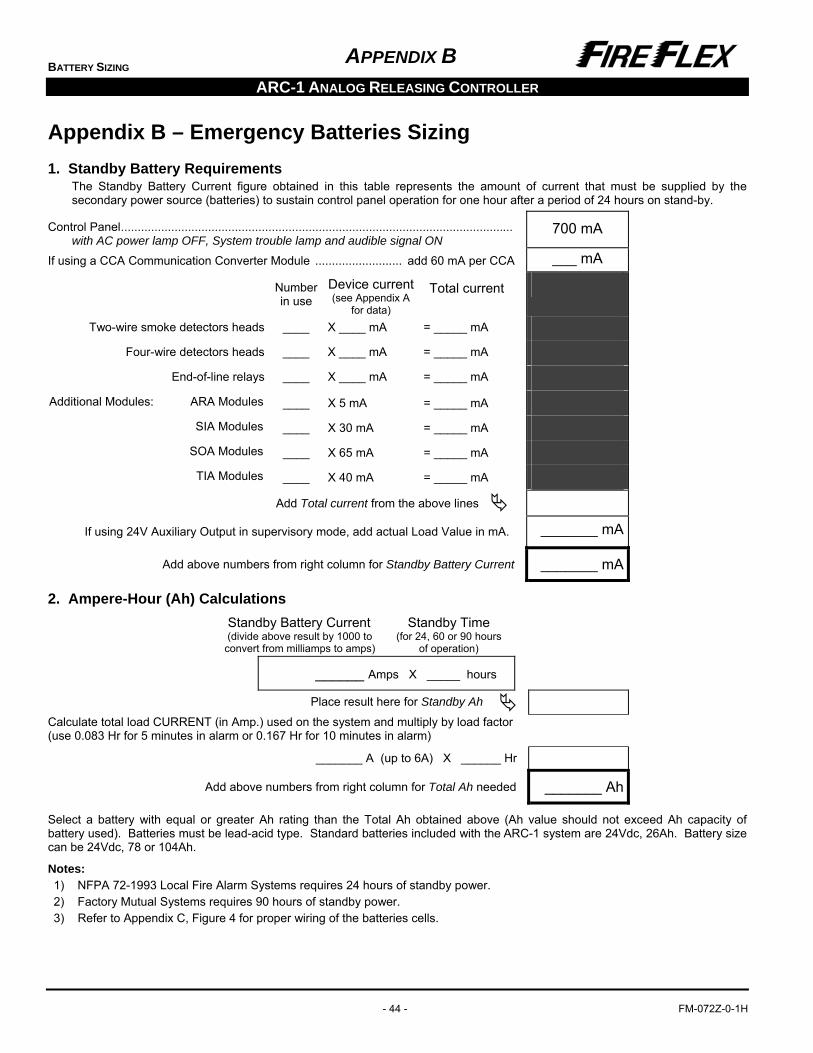
BATTERY SIZING APPENDIX B ARC-1 ANALOG RELEASING CONTROLLER
- 44 - FM-072Z-0-1H
Appendix B – Emergency Batteries Sizing 1. Standby Battery Requirements
The Standby Battery Current figure obtained in this table represents the amount of current that must be supplied by the secondary power source (batteries) to sustain control panel operation for one hour after a period of 24 hours on stand-by.
Control Panel..................................................................................................................... with AC power lamp OFF, System trouble lamp and audible signal ON
700 mA
If using a CCA Communication Converter Module .......................... add 60 mA per CCA ___ mA
Number in use
Device current(see Appendix A
for data) Total current
Two-wire smoke detectors heads ____ X ____ mA = _____ mA Four-wire detectors heads ____ X ____ mA = _____ mA
End-of-line relays ____ X ____ mA = _____ mA Additional Modules: ARA Modules ____ X 5 mA = _____ mA
SIA Modules ____ X 30 mA = _____ mA SOA Modules ____ X 65 mA = _____ mA TIA Modules ____ X 40 mA = _____ mA
Add Total current from the above lines
If using 24V Auxiliary Output in supervisory mode, add actual Load Value in mA. _______ mA
Add above numbers from right column for Standby Battery Current _______ mA
2. Ampere-Hour (Ah) Calculations Standby Battery Current (divide above result by 1000 to
convert from milliamps to amps)
Standby Time (for 24, 60 or 90 hours
of operation)
______ Amps X _____ hours
Place result here for Standby Ah Calculate total load CURRENT (in Amp.) used on the system and multiply by load factor (use 0.083 Hr for 5 minutes in alarm or 0.167 Hr for 10 minutes in alarm)
_______ A (up to 6A) X ______ Hr
Add above numbers from right column for Total Ah needed _______ Ah
Select a battery with equal or greater Ah rating than the Total Ah obtained above (Ah value should not exceed Ah capacity of battery used). Batteries must be lead-acid type. Standard batteries included with the ARC-1 system are 24Vdc, 26Ah. Battery size can be 24Vdc, 78 or 104Ah.
Notes: 1) NFPA 72-1993 Local Fire Alarm Systems requires 24 hours of standby power. 2) Factory Mutual Systems requires 90 hours of standby power. 3) Refer to Appendix C, Figure 4 for proper wiring of the batteries cells.

APPENDIX C
CABINET DETAILS & WIRING ROUTING ARC-1 ANALOG RELEASING CONTROLLER
FM-072Z-0-1H - 45 -
Appendix C – Cabinet Details / Wiring Routing Cabinet Details The ARC-1 cabinet is made of sturdy 14 gauge steel, measuring 36" x 20" x 14" (91,4 x 50,8 x 35,5 cm) or 46" x 24" x 14" (116,8 x 61 x 35,5 cm). Refer to Figure 1 for detail. All surfaces are rust proof coated, inside and outside, with fire red, oven baked polyester powder on phosphate base. Cabinet is provided with individual access doors for the hydraulic and electrical sections and the emergency release with a neoprene gasket to avoid vibrations. Knockouts can be drilled by the installing contractor on-site but have to meet the restrictions indicated on Figure 2.
IMPORTANT! Units are NOT designed to be installed where they will be subjected to outdoors and/or freezing conditions. Refer to ENVIRONMENTAL DATA for additional details. Subjecting the unit to conditions outside these limitations might hamper the normal operation of the system.
Cabinet doors are provided with hinges that can easily be disassembled on site to remove the door assemblies for servicing. The cabinet assembly is pre-assembled, pre-wired, and factory tested under ISO-9001 conditions.
Note: The mechanical and electrical sections are provided in two separate enclosures, stacked one on top of the other.
Drilling:
When drilling in the cabinet to install wiring conduits or pipes, use only the areas of the cabinet shown below to avoid drilling into internal components.
Figure 2 – Drilling detail: IMPORTANT ! Drill holes in the three shadedareas only to avoid internal components andabout 1/2" from cabinet edges as shown.
5"
3"
9"
15"
3"
Figure 1 – Dimensions:
A C
FM-072C-0-238 A.doc
2" MAX.
D
ARC-1®Analog Release COntroller
B
Cabinet Size A B C D
Small 36" 14" 20" 34"
Large 46" 14" 24" 38"

CABINET DETAILS & WIRING ROUTING APPENDIX C
ARC-1 ANALOG RELEASING CONTROLLER
- 46 - FM-072Z-0-1H
Wiring Routing
Wiring shown in Figure 3 below indicates typical Wiring Routing for Power Limited Circuits. Refer to FIELD WIRING DIAGRAM and drilling guide above for additional details.
Figure 3 – Wiring routing:
Knock-outs (drilled by contractor)Typical Shielded wiring
Power-limited Circuits wiringAC Power Supply Wiring
Factory wiring
1 2 A B C 3 4 5 6 7 8 9Blank
PSA
BCA
TBA
TBBTBB
Blank Blank Blank Blank
Y
R
TIA SCA GIA SSA SIA SOA ARA
Y
R
FM-0
72C
-0-2
54 D
.dw
gWiring Routing Guide
Figure 4 – Batteries Cells Wiring Detail:
26Ah Battery Set 78Ah Battery Set
104Ah Battery Set
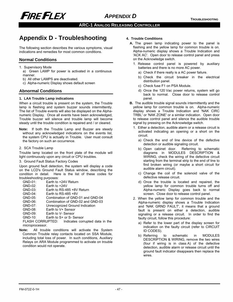
APPENDIX D TROUBLESHOOTING ARC-1 ANALOG RELEASING CONTROLLER
FM-072Z-0-1H - 47 -
Appendix D - Troubleshooting The following section describes the various symptoms, visual indications and remedies for most common conditions.
Normal Conditions
1. Supervisory Mode a) Green LAMP for power is activated in a continuous manner. b) All other LAMPS are deactivated. c) Alpha-numeric Display shows default screen
Abnormal Conditions
1. LAA Trouble Lamp indications When a circuit trouble is present on the system, the Trouble lamp is flashing and system buzzer sounds intermittently. The list of Trouble events will also be displayed on the Alpha-numeric Display. Once all events have been acknowledged, Trouble buzzer will silence and trouble lamp will become steady until the trouble condition is repaired and / or cleared.
Note: If both the Trouble Lamp and Buzzer are steady without any acknowledged indications on the events list, the system CPU is actually in Trouble. User must consult the factory on such an occurrence.
2. SCA Trouble Lamp Trouble lamp located on the front plate of the module will light continuously upon any circuit or CPU troubles. 3. Ground Fault Status Factory Codes Upon ground fault detection, the system will display a code on the LCD's Ground Fault Status window, describing the condition in detail. Here is the list of these codes for troubleshooting purposes:
GND-01: Earth to +24V Return GND-02: Earth to +24V GND-03: Earth to RS-485 +8V Return GND-04: Earth to RS-485 +8V GND-05: Combination of GND-01 and GND-04 GND-06: Combination of GND-02 and GND-03 GND-07: Unrecognized Ground Indication GND-08: Earth to V+ Sensor GND-09: Earth to V- Sensor GND-10: Earth to S+ or S- Sensor FLASH CORRUPTED: Indicates corrupted data in the microprocessor.
Note: All trouble conditions will activate the System Common Trouble relay contacts located on SSA Module, including total loss of power. In such conditions, Auxiliary Relays on ARA Module programmed to activate on trouble condition would not operate.
4. Trouble Conditions A. The green lamp indicating power to the panel is
flashing and the yellow lamp for common trouble is on. Alpha-numeric display shows a Trouble Indication and 'ACK AC'. Open door to release control panel and press on the Acknowledge switch. 1. Release control panel is powered by auxiliary
batteries and there is no more AC power. a) Check if there really is a AC power failure. b) Check the circuit breaker in the electrical
distribution panel. c) Check fuse F1 on PSA Module. d) Once the 120 Vac power returns, system will go
back to normal. Close door to release control panel.
B. The audible trouble signal sounds intermittently and the yellow lamp for common trouble is on. Alpha-numeric display shows a Trouble Indication and 'NAK CIRC TRBL' or 'NAK ZONE' or a similar indication. Open door to release control panel and silence the audible trouble signal by pressing on the Acknowledge switch. 1. Either a detection, audible alarm or a release circuit is
activated indicating an opening or a short on the circuit. a) Check the end of line device of the defective
detection or audible signaling circuit. b) Open cabinet door. Referring to schematic
diagrams in MODULES DESCRIPTION & WIRING, check the wiring of the defective circuit starting from the terminal strip to the end of line to find broken wiring (or maybe a short circuit for audible alarm circuit).
c) Change the coil of the solenoid valve of the defective release circuit.
d) Once the trouble is located and repaired, the yellow lamp for common trouble turns off and Alpha-numeric Display goes back to normal screen. Close door to release control panel.
2. When the yellow lamp for common trouble and the Alpha-numeric display shows a Trouble Indication and 'NAK GRND FAULT', it means that a ground fault is present on either a detection, audible signaling or a release circuit. In order to find the faulty circuit, follow this procedure: a) Refer to the lower part of the display screen for
indication on the faulty circuit (refer to CIRCUIT ID CODES).
b) Referring to schematic in MODULES DESCRIPTION & WIRING, remove the two wires (four if wiring is in class A) of the defective detection, audible alarm or release circuit until the ground fault indicator disappears then replace the wires.
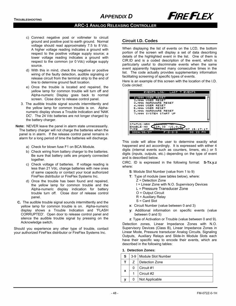
TROUBLESHOOTING APPENDIX D
ARC-1 ANALOG RELEASING CONTROLLER
- 48 - FM-072Z-0-1H
c) Connect negative post or voltmeter to circuit ground and positive post to earth ground. Normal voltage should read approximately 7.5 to 8 Vdc. A higher voltage reading indicates a ground with respect to the positive voltage supply source; a lower voltage reading indicates a ground with respect to the common (or 0 Vdc) voltage supply source.
d) With this in mind, check the negative or positive wiring of the faulty detection, audible signaling or release circuit from the terminal strip to the end of line to determine ground fault location.
e) Once the trouble is located and repaired, the yellow lamp for common trouble will turn off and Alpha-numeric Display goes back to normal screen. Close door to release control panel.
3. The audible trouble signal sounds intermittently and the yellow lamp for common trouble is on. Alpha-numeric display shows a Trouble Indication and 'NAK DC'. The 24 Vdc batteries are not longer charged by the battery charger.
Note: NEVER leave the panel in alarm state unnecessarily. The battery charger will not charge the batteries when the panel is in alarm. If the release control panel remains in alarm for a long period of time the batteries will discharge.
a) Check for blown fuse F1 on BCA Module. b) Check wiring from battery charger to the batteries.
Be sure that battery cells are properly connected together.
c) Check voltage of batteries. If voltage reading is less than 21 Vdc, change batteries with new ones of same capacity or contact your local authorized FireFlex distributor or FireFlex Systems Inc.
d) Once the trouble has been found and repaired, the yellow lamp for common trouble and the Alpha-numeric display indication for battery trouble turn off. Close door of release control panel.
C. The audible trouble signal sounds intermittently and the yellow lamp for common trouble is on. Alpha-numeric display shows a Trouble Indication and 'FLASH CORRUPTED'. Open door to release control panel and silence the audible trouble signal by pressing on the Acknowledge switch.
Should you experience any other type of trouble, contact your authorized FireFlex distributor or FireFlex Systems Inc.
Circuit I.D. Codes
When displaying the list of events on the LCD, the bottom portion of the screen will display a set of data describing details of the highlighted event in the list. One of them is CIR.ID and is a coded description of the event, which is particularly useful to discriminate events when the same event apparently happened many consecutive times in the list. The code actually provides supplementary information facilitating screening of specific types of events. Here is an example of this screen with the location of the I.D. Code circled:
This code will allow the user to determine exactly what happened and act accordingly. It is expressed with either 4 digits (internal events such as counters, timers, etc.) or 5 digits (inputs, outputs, etc.) depending on the type of event and is described below. CIRC. ID is expressed in the following format: S-Tx.y.z where:
S: Module Slot Number (value from 1 to 9) T: Type of module (see tables below), where:
Z = Detection Zone I = Linear Zone with N.O. Supervisory Devices L = Pressure Transducer Zone O = Output Circuit R = Auxiliary Relay S = Card Slot
x: Circuit Number (value between 0 and 3) y: Additional information on specific events (value
between 0 and 5) z: Type of Activation or Trouble (value between 0 and 9).
Detection zones, Linear Impedance Zones with N.O. Supervisory Devices (Class B), Linear Impedance Zones in Linear Mode, Pressure transducer Analog Circuits, Signaling Outputs, Auxiliary Relays and Slide-In Module Slots each have their specific way to encode their events, which are described in the following tables:
1. Detection Zones:
S 3-9 Module Slot Number T Z Detection Zone
0 Circuit #1 x
1 Circuit #2 y 0 Not Applicable

APPENDIX D TROUBLESHOOTING ARC-1 ANALOG RELEASING CONTROLLER
FM-072Z-0-1H - 49 -
0 Short Circuit Alarm (or Trouble/Supervisory) 1 Open Loop Trouble (or Alarm) 2 Dual End of Line Resistor Trouble 6 Module trouble (wrong type) 7 Configuration Trouble
(inappropriate configuration) 8 Default Configuration Changed
z
9 Enable / Disable
Examples of Detection Zones Event Codes: Zone 1 in alarm: 3-Z0.0.0 Zone 1 in Trouble: 3-Z0.0.1 Zone 2 in Alarm: 3-Z1.0.0 Zone 2 in Trouble: 3-Z1.0.1
2. Linear Impedance Zones with field wired N.O. Supervisory Devices (Class B) in 'DET' Mode:
S 3-9 Module Slot Number T I Dry Contact Zone
0 Circuit #1 x
1 Circuit #2 y 0 Not Applicable
0 Short Circuit Alarm (or Trouble/Supervisory) 1 Open Loop Trouble (or Alarm) 6 Module trouble (wrong type) 7 Configuration Trouble
(inappropriate configuration) 8 Default Configuration Changed
z
9 Enable / Disable
Example of Linear Impedance Zones Event Code: Linear Zone 2 in Detection Mode: 3-I1.0.0
3. Linear Impedance Zones with factory wired N.O. Supervisory Devices (linear) in 'LIN' Mode:
S 3-9 Module Slot Number T I Dry Contact Zone
0 Circuit #1 x
1 Circuit #2 0 Device #1 1 Device #2 y 2 Device #3 0 Short Circuit Alarm (or Trouble/Supervisory) 1 Open Loop Trouble (or Alarm) 6 Module trouble (wrong type) 7 Configuration Trouble
(inappropriate configuration) 8 Default Configuration Changed
z
9 Enable / Disable
Examples of Linear Impedance Zones Event Codes: Linear Zone 1 in Linear Mode (Lin 1.1): 3-I0.0.0 Linear Zone 1 in Linear Mode (Lin 1.3): 3-I0.2.0
4. Pressure transducer Analog Circuits:
S 1-2 Module Slot Number T L Pressure Transducer Circuit
0 Sensor #1 1 Sensor #2 x 2 Sensor #3 0 Very Low Pressure
(applicable only for sensor in Slot #1) 1 Low Pressure 2 High Pressure 3 Very High Pressure
y
4-5 See below 0 Activated Set-Point 6 Module trouble (wrong type) 7 Configuration Trouble
(inappropriate configuration) 8 Default Configuration Changed
z
9 Enable / Disable
If a code '4' is shown in the 'y' digit, signifying Trouble Group A, then the 'z' digits will be replaced by the following codes:
0 Calibration Trouble 1 Ground Fault V+ 2 Ground Fault V- 3 Ground Fault S+ or S- 4 Unrecognized Ground Fault
z
5 V+ Open
If a code '5' is shown in the 'y' digit, signifying Trouble Group B, then the 'z' digits will be replaced by the following codes:
0 Short between V- & S+ 1 Short between V- & S- 2 Short between V+ & S+ 3 Short between V+ & S- 4 Short between V+ / V– or V+ Open
z
5 S+ or S- Open or Sensor out of range
Examples of Analog Zone Event Code: Sensor 1 Set-point 1: 1-L0.0.0 Sensor 1 Trouble: 1-L0.4.0
Example of Sensor Trouble Event Code: Sensor 1 Trouble: 1-L0.4.0
TROUBLESHOOTING APPENDIX D
ARC-1 ANALOG RELEASING CONTROLLER
- 50 - FM-072Z-0-1H
5. Signaling Outputs:
S 3-9 Module Slot Number T O Signaling Output
0 Circuit #1 1 Circuit #2 x 2 Circuit #3
y 0 Not Applicable 0 Output Activated 1 Open Loop Trouble 2 Short Circuit 3 Dual End of Line Device Trouble 4 Coil removed from body 5 Unrecognized Trouble 6 Module trouble (wrong type) 7 Configuration Trouble
(inappropriate configuration) 8 Default Configuration Changed
z
9 Enable / Disable
Example of Signaling Output Event Code: Output 1 Trouble: 6-O0.0.5
6. Auxiliary Relays:
S 3-9 Module Slot Number T R Auxiliary Relay
0 Relay #1 1 Relay #2 2 Relay #3
x
3 Relay #4 y 0 Not Applicable
0 Relay Activated 6 Module trouble (wrong type) 7 Configuration Trouble
(inappropriate configuration) 8 Default Configuration Changed
z
9 Enable / Disable
Example of Relay Event Code: Relay 3 Activated: 8-R2.0.0
7. Slide-In Module Slots:
S 3-9 Module Slot Number T S Module Slot Error x 0 Not Applicable y 0 Not Applicable
0 Standard Module Missing 1 Module Not Responding 2 Module Added 3 Module removed 4 Module Wrong Type 5 Module Added Live
z
6 Module Loading Error
Example of Slide-In Modules Slot Event Codes: Module in Slot 3 missing: 3-S0.0.0
Internal Events ID Codes
Internal events such as counters, timers, etc. will not display the first S digit for slot number since they are system events, and are not related to the input/output cards therefore, they are using a 4 digits ID Code only. Internal Events CIRC. ID is expressed in the following format: Tx.y.z where;
T: Type of internal event (see tables below), where: C = Cycles Counter T = Timer Y = Cycling Timer D = Detection Groups V = Variables X = Network P = Pseudos E = Error Messages U = User Messages
x: Circuit Number (value between 0 and 3) y: Additional information on specific events (value
between 0 and 5) z: Type of Activation or Trouble (value between 0 and
9).
Cycle Counters, Timers, Cycling Timers, Detection Groups, Variables, Networks, Pseudos, Error Messages and User Messages each have their specific way to encode their events, which are described in the following tables:
APPENDIX D TROUBLESHOOTING ARC-1 ANALOG RELEASING CONTROLLER
FM-072Z-0-1H - 51 -
1. Cycles Counters:
T C Cycles Counter 0 Counter #1 1 Counter #2 2 Counter #3
x
3 Counter #4 y 0 Not Applicable
0 Counter Increment 1 Counter Paused 2 Counter Ended 3 Counter Increment Confirmed
z
4 Counter Resetted
Example of Counter Event Code: Counter 2 Paused: C1.0.1
2. Timers:
T T Timer 0 Timer #1 1 Timer #2 x 2 Timer #3
y 0 Not Applicable 0 Timer Started 1 Timer Paused 2 Timer Expired
z
5 Timer Resetted
Examples of Timer Event Codes: Timer 1 Started: T0.0.0 Timer 1 Expired: T0.0.2 Timer 2 Started: T1.0.0
3. Cycling Timers:
T Y Cycling Timer 0 Cycling Timer #1
x 1 Cycling Timer #2
y 0 Not Applicable 0 Cycling Timer Started 1 Cycling Timer Paused 2 Both Cycles Expired 3 Activated Session: 0 = Session 1
1 = Session 2 4 Session On / Off
z
5 Cycling Timer Resetted
Examples of Cycling Timer Event Codes: Cycling Timer 1 Started: Y0.0.0 Cycling Timer 1 Expired: Y0.0.2 Cycling Timer 2 Started: Y1.0.0
4. Detection Groups:
T D Detection Groups 0 Message 1 1 Message 2 2 Message 3 3 Message 4
x
4 Message 5 0 Zone 1
y 1 Zone 2 0 Set Point Activation 1 General Trouble z 2 End of Line Trouble
Examples of Detection Group Event Codes: Detection Group 1 Trouble: D0.1.0 Detection Group 1 End of Line Trouble: D0.1.2
5. Variables:
T V Variables 0 Message 1 1 Message 2 2 Message 3 … …
x
99 Message 100 y 0 Not Applicable z 0 Activation Type
Examples of Variable Event Codes: Variable 1: V0.0.0 Variable 16: V15.0.0
6. Local Network Variables:
T X Network 0 Message 1 1 Message 2 2 Message 3 … …
x
29 Message 30 y 0 Not Applicable z 0 Activation Type
Example of Local Network Variable Event Code: Variable 3: X2.0.0

TROUBLESHOOTING APPENDIX D
ARC-1 ANALOG RELEASING CONTROLLER
- 52 - FM-072Z-0-1H
7. Pseudos:
T P Pseudos 0 Message 1 1 Message 2 2 Message 3 … …
x
99 Message 100 y 0 Not Applicable z 0 Activation Type
Example of Pseudo Event Code: Pseudo 1: P0.0.0
8. Error Codes:
T E Errors 0 Message 1 1 Message 2 2 Message 3 … …
x
199 Message 200 y 0 Not Applicable z 0 Activation Type
Example of Error Code: Error 75: E74.0.0
9. User Messages:
T U User Messages 0 Message 1 1 Message 2 2 Message 3 … …
x
99 Message 100 0 Additional Info. 1 1 Additional Info. 2 2 Additional Info. 3 … …
y
199 Additional Info. 200 z 0 Activation Type
Example of User message Event Code: User Message 2: U1.0.0
Events Type Codes
Events log bottom window also displays a coded description of the events types. Here is the list of those codes:
Code Description ALM Alarm CAD Card Added CC Short Circuit CEL Card Error Load CHC Circuit Choice CNF Configuration Circ. CIR Circuit CNR Card Not Responding CRD Card Trouble CRM Card Removed CO Open Circuit COI Coil CO+ Open Circuit S+ CO- Open Circuit S- DBE Double EOL Resistor DIS Disable ECT General Trouble EOL End of Line GS+ Ground Fault S+ GS- Ground Fault S- G0V Ground Fault 0V G5V Ground Fault 5V LAD Card Added Live NOP Non Action Event RST Reset SCC Short-circuit S+/S- SNS General Sensor Trouble SUP Supervisory WTP Wrong Type of Card ??? Unknown Trouble

USER NOTES ARC-1 ANALOG RELEASING CONTROLLER
FM-072Z-0-1H - 53 -
Notes
WARRANTY ARC-1 ANALOG RELEASING CONTROLLER
- 54 - FM-072Z-0-1H
Limited Warranty
FireFlex Systems inc. (known herein as "the Manufacturer") warrants to its customers that its products shall be free of defects in material [or part(s)] and workmanship for a period of twelve (12) months from the date of original purchase by the Customer, under normal use and service by the Customer (and provided that the product has been properly installed and maintained). The obligation of the Manufacturer is case of a claim made by the Customer hereunder, shall be, at the Manufacturer's option, to repair or replace, free of charge for parts or labor, any product or part, which in the opinion of the Manufacturer, shall be proven to be defective. The present warranty shall be void should the product [or part(s)] be altered by anyone other than the Manufacturer. In case of a claim under the present warranty, the Customer must contact the Manufacturer's Customer Service Department as soon as he is aware of a claim and, subject to the authorization of the manufacturer, return the defective product [or part(s)], transportation prepaid, to the address listed below. This warranty constitutes the entire warranty given by the Manufacturer to the Customer with respect to the product. The present warranty is non-transferable and non-assignable. The Manufacturer does not represent that the products will prevent any loss by fire or otherwise or that the product will in all cases provide the protection for which it has been installed or intended. The Customer acknowledges that the Manufacturer is not an insurer. The manufacturer shall not be liable for any loss or damages of any nature whatsoever, including but not limited to incidental or special or consequential damages including but not limited to, property damages, personal injury, revenue loss or lost profits, inconveniences, transportation charges or other damages suffered by anyone. There are no other warranties, expressed or implied with regard to the products, other than those contained herein.
Some jurisdictions may not allow limitations on how long an expressed warranty lasts, so the above limitations may not apply to you. Under no circumstances, shall the Manufacturer be liable for any loss of, or damage to property, direct or indirect, incidental or special or consequential damages, arising out of the use or inability to use the Manufacturer's products. The Manufacturer shall not be liable for any personal injury which may arise in the course of or as a result of the use of the manufacturer's products. This warranty replaces all previous warranties and is the only warranty given by the Manufacturer with respect to its products. This warranty shall not be modified, unless such modification is made in writing by an executive officer of the Manufacturer. In consideration of the warranty provisions contained herein, the Customer hereby waives the benefit of any statutory warranty or protection or remedy to which he may be entitled under the terms of any sales of goods act or similar legislation available to him in any jurisdiction in which the Customer carries on business.
Special Limitation: Due to their self discharge characteristics when not charged during extended storage periods, batteries supplied with releasing control panels are covered by the above warranty for a period limited to three (3) months only.
FireFlex Systems inc.
1935, Lionel-Bertrand Blvd. Boisbriand, Quebec
Canada J7H 1N8
Tel.: (450) 437-3473 - Fax: (450) 437-1930 Toll Free: (866) 347-3353
Web site: http://www.fireflex.com

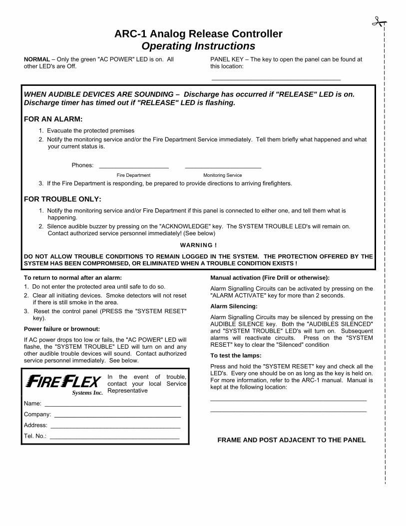
ARC-1 Analog Release Controller Operating Instructions
NORMAL – Only the green "AC POWER" LED is on. All other LED's are Off.
PANEL KEY – The key to open the panel can be found at this location:
_______________________________________
WHEN AUDIBLE DEVICES ARE SOUNDING – Discharge has occurred if "RELEASE" LED is on. Discharge timer has timed out if "RELEASE" LED is flashing.
FOR AN ALARM: 1. Evacuate the protected premises 2. Notify the monitoring service and/or the Fire Department Service immediately. Tell them briefly what happened and what
your current status is.
Phones: _____________________ _______________________ Fire Department Monitoring Service
3. If the Fire Department is responding, be prepared to provide directions to arriving firefighters.
FOR TROUBLE ONLY: 1. Notify the monitoring service and/or Fire Department if this panel is connected to either one, and tell them what is
happening. 2. Silence audible buzzer by pressing on the "ACKNOWLEDGE" key. The SYSTEM TROUBLE LED's will remain on.
Contact authorized service personnel immediately! (See below)
WARNING !
DO NOT ALLOW TROUBLE CONDITIONS TO REMAIN LOGGED IN THE SYSTEM. THE PROTECTION OFFERED BY THE SYSTEM HAS BEEN COMPROMISED, OR ELIMINATED WHEN A TROUBLE CONDITION EXISTS !
To return to normal after an alarm: 1. Do not enter the protected area until safe to do so. 2. Clear all initiating devices. Smoke detectors will not reset
if there is still smoke in the area. 3. Reset the control panel (PRESS the "SYSTEM RESET"
key).
Power failure or brownout:
If AC power drops too low or fails, the "AC POWER" LED will flashe, the "SYSTEM TROUBLE" LED will turn on and any other audible trouble devices will sound. Contact authorized service personnel immediately. See below.
Systems Inc.
In the event of trouble, contact your local ServiceRepresentative
Name: _________________________________________
Company: ______________________________________
Address: _______________________________________
Tel. No.: _______________________________________
Manual activation (Fire Drill or otherwise):
Alarm Signalling Circuits can be activated by pressing on the "ALARM ACTIVATE" key for more than 2 seconds.
Alarm Silencing:
Alarm Signalling Circuits may be silenced by pressing on the AUDIBLE SILENCE key. Both the "AUDIBLES SILENCED" and "SYSTEM TROUBLE" LED's will turn on. Subsequent alarms will reactivate circuits. Press on the "SYSTEM RESET" key to clear the "Silenced" condition
To test the lamps:
Press and hold the "SYSTEM RESET" key and check all the LED's. Every one should be on as long as the key is held on. For more information, refer to the ARC-1 manual. Manual is kept at the following location:
_______________________________________________
_______________________________________________
FRAME AND POST ADJACENT TO THE PANEL