analog mixed-signal simulation results with cadence hierac · 2018-11-13 · analog mixed-signal...
TRANSCRIPT

Analog Mixed-Signal Simulation in FE-I4 with Cadence AMS Designer
Vladimir Zivkovic
Nikhef institute
Amsterdam, The Netherlands
18/25/2010 Vladimir Zivkovic, NIKHEF

Outline
• Introduction
• Analog Mixed-Signal (AMS) Simulation Framework in FEI4-A – proof of concept
• Further steps
28/25/2010 Vladimir Zivkovic, NIKHEF

Why AMS Simulation?
• Bridge the gap between system-level and implementation
• Improve system and block performance analyses
– Addressing difficult to predict interactions e.g. substrate, supplies,…
• Combine best known analog simulation techniques with digital verification methodology (within an EDA tool)
• Assists during analog verification steps
38/25/2010 Vladimir Zivkovic, NIKHEF

What is the AMS Simulation?
• Simulates a network that contains nodes and branches of analog natures as well as ports of models of discrete nature,
• Synchronizes the analog solver with Newton methods (Spectre, UltraSim) and the digital kernel with event driven simulator (ncsim),
• Supports modules described at various levels of abstraction (netlists, behavioral models, black-boxes).
48/25/2010 Vladimir Zivkovic, NIKHEF

AMS Designer Features
• A flow composed of several executables integrated in Virtuoso custom IC design flow enabling AMS simulation through the support of mixed-signal behavioral languages (verilog.ams)
• Deals with schematics and text netlists
• Encompasses environment for simulation and debugging
• Supports both analog and digital centric methodology
• Has three usage models– Analog Design Environment (ADE)
– Hierarchy Editor (HED)
– Command line
58/25/2010 Vladimir Zivkovic, NIKHEF
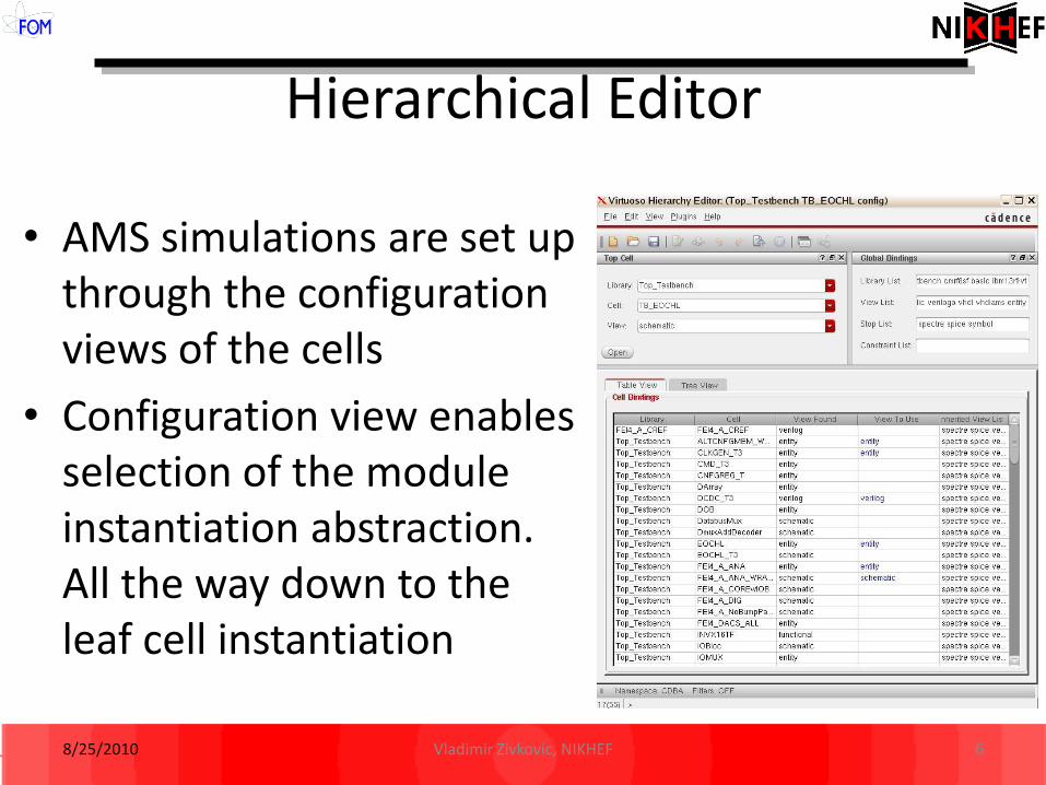
Hierarchical Editor
• AMS simulations are set up through the configuration views of the cells
• Configuration view enables selection of the module instantiation abstraction. All the way down to the leaf cell instantiation
68/25/2010 Vladimir Zivkovic, NIKHEF

AMS HED Plugin
ncvlog
Hdl.var .pak (inca_file)
Compiled models
Simulation Snapshot
ncsim
simvision tcl
simviews
Netlist
Digital vs AMS Designer Flow
7
ncelab
Wavescan
.scs(control
file)
ncsimSpectre
Ultrasim
Design Database
SchematicConfig
Connect lib
Connect Modules
amsDirect(netlister)
PDK
SpectreModels
CDF
Cdsglobals(vams)
Behavioral
.v, .vams
8/25/2010 Vladimir Zivkovic, NIKHEF

AMS Simulation in FEI4
• An Example: FEI4-A Power up sequence
– All pads described with their schematic (transistor level)
– FEI4_DIG schematic, with digital modules being powered up described with verilog (after layout)
– FEI4_ANA black box
– Power-up sequence (testbench) in Verilog.AMS
88/25/2010 Vladimir Zivkovic, NIKHEF

Power-up Sequence
9
1) Initialization2) VDDT3 <- 1.2
Wait 5us3) RD1_bar
VDDD1 <- 1.2VWait 1usRD1_bar Wait 5us
4) RDA_barVDDA1 <- 1.65VWait 1us
RDA_bar...
8/25/2010 Vladimir Zivkovic, NIKHEF

Top level configuration
108/25/2010 Vladimir Zivkovic, NIKHEF

Configuration with HED
118/25/2010 Vladimir Zivkovic, NIKHEF

AMS HED Plugin
128/25/2010 Vladimir Zivkovic, NIKHEF

Simulation Charts (I)
138/25/2010 Vladimir Zivkovic, NIKHEF

Simulation Charts (II)
8/25/2010 Vladimir Zivkovic, NIKHEF 14

Simulation Charts (III)
8/25/2010 Vladimir Zivkovic, NIKHEF 15

Further development
• Verify the remaining functionality/performance that is not being checked – too late in FEI4-A ? Postponed for the next version ? In any case, we can agree on verification plan driven from the top-level (self-checking test-benches) for at least debug purposes.
• Couple the approach with OVM ?
• Expand the approach to include the elements of the probe card and verify the test setup for AMS circuits as well as the debug purpose?
168/25/2010 Vladimir Zivkovic, NIKHEF

Self-checking test-bench
8/25/2010 Vladimir Zivkovic, NIKHEF 17

Test Setup Validation
8/25/2010 Vladimir Zivkovic, NIKHEF 18
PCB
C1
clkin
vdda
GNDA
R1
R5
Pulse
GNDD
vdd2vdd1
R R R
R2 R3
C2
C3
C4
vin_1
vin_2
dig_out
I/O I/O
vout1
vout2
Power Power Power
Vsin
Vsin
I/O
relay2
relay1
trig
trig
trig
trig
trig
trig trig
trig
trig
Bench-test
trig
I/O
LogicAnalyzer
Digitizer
FEI4-A(various abstraction levels)
R
R