analysis and azimuth, dao sear~ier …. these observations ... tilt about the gyro spin axis, and...
TRANSCRIPT
/ DAO A0 446 AIR FORCE OPHYSICS LAB HN SCOM Are M A pig 17,0ERROR ANALYSIS AND PERFORMANCE DATA PFUN AN AUTOMATED AZIMUTH, -ETC "c'.FE3SI 61 A SEAR~IER .J A NIOLA. H MWSOPP
UNCLASSIFIED AFLTW41-0033 N
~EEEEEEEINE
ERROR jkNALYSIS AND PERORMANCE 2ATA FROM AN
-- 5UTOMATED 4ZIMUTH LIEASURING SYSTEMJames A./Shearer; Joseph A./Miolae, . of,
A.Howard Mu.sctfThe Charles Stark Draper Laboratory, Inc. "'
Cambridge, Massachusetts
and
David/Anthony_,=±t Robert J. Gauthier 1 Lt. James M. Novak,
Air Force Geophysics Laboratory
~STACT Hanscom AFB, Massachusetts LEV ZLABSTRACT LE•
The determination of precise time-
dependent azimuths is an important
Z) requirement for evaluation and maintenance
of inertial navigation instruments. /rm
Improved technology now demands a test and
evluation accuracy of less than one arc
second, which means that geophysical and,
environmental effects on the time-stability
of azimuth references are now quite
significant. Similarly, az.muthal motions
of the test eqiiipment, which are inherent '
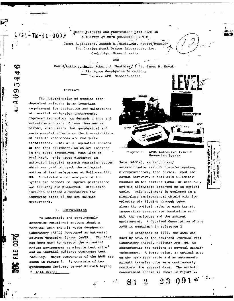
in the tests themselves, must also be Figure 1. AFGL Automated AzimuthMeasuring System !evaluated. This paper discusses an
automated inertial azimuth measuring system Sets (ALS's), an inductosyn/
which was used to track the azimuthal autocollimator azimuth transfer system, Z 8-motion of test references at Holloman AFB, microprocessors, tape drives, input and i
NM. A detailed error analysis of the output hardware, a dual-axis tiltmeter
ystem and methods to improve performance mounted on the azimuth gimbal of each ALS,and accuracy are presented. Discussion and six tiltmeters arranged on an opticalincludes selected alternatives for table. This equipment is enclosed in a
improving state-of-the art azimuth plexiglass environmental shield with low
measurement, velocity air flowing through tubes
along the optical paths to each target.1 . Introduction Temperature sensors are located in each
To accurately and continuously ALS, the enclosure and the ambient
determine rotational motions about a environment. A detailed description of the
vertical axis the Air Force Geophvsics AAMS is contained in reference 2.
Laboratory (AFGL) developed an Automated In September of 1979, the AAMS was
Azimuth Measuring System (AAMS). The AAMS used by AFGL at the Advanced Inertial Test
C) has been used to measure the azimuthal Laboratory (AITL), Holloman AFB, NM, to
motion environment at missile test silos1 characterize the motions of several azimuthLa. and an inertial guidance component test references. A Porro prism, an optical cube
facility. Major components of the AAMS are on the gyro test table and an astronomic
shown in Figure 1. It consists of two azimuth transfer cube were continuously
gyrocompass devices, termed Azimuth Laying monitored for several days. The azimuth
* AIAA Member measurement scheme is shown in Figure 2.
A- 81 2 23 091 -If;

SECURITYUNCLASFIFIED
Sat-YCLASSIFICATION Dy THIS PAGE (h o 19..d
READ INSTRUCTIONSRE OR OM ENTAIONGEBEFORE COMPLETING FORM
REPORT, NU*IOT ACCESSION No. S. RECIPIENTS, CATALOG NUMBER
AFGL-TR-81-0033 "9 'q5-W /4. TITLE (and SbtiIII) S. TYPE OF REPORT 6 PERIOD COVERED
Error Analysis and Performa~nce Data from Automated ReprintAzimuth measuring System
B. PERFORMING ORG. REPORT NUMBER
7. AUTHOR(-) 9. CONTRACT OR4 GRANT NUMBER(.)
James A. Shearer, Joseph A. Miola, Howard Musoff,David Anthony, Robert J. Gauthier and James M.
~6 _ ___ ___ ____ ___ ___ _ __ __Novak__
9.iPERFORMING ORGANIZATION NAME AND ADDRESS 10. PROGRAM ELEMENT PRODJECT, TASKAir Force Geophysics Laboratory/LWHi CA OK1NITHU F R
Hanscom AFB21FMassachusetts 01731 1010
$I. CONTROLLING OFFICE NAME AND ADDRESS 12. REPORT DATE
t '..Air Force Geophysics Laboratory/LWI 17 February 1981Hanscom AFB 13. NUMBER OF PAGESMassachusetts 01731914 MONITORING AGENCY NAME & ADDRESSII different from, ControIIinig Office) IS. SECURITY CLASS. (of Ing. report)
UNCLASSIFIED
IS.. OECLASSi FICA-IOH OOWINGRADINGjSCHED4ULE
F1 Approved for public release; distribution unlimited.
17. DISTRIBUTION STATEMENT (ofIAh. bOI,..teI .o.d of, inlock 20, if dill,,.,, from, Report)
ISUPPLEMENTARY NOTES
Prep ared in cooperation with the Charles Stark Draper Laboratory, Inc. , CambridgfMA; presented at conference of AIMA, Danvers, MA.
19. K EY W'ORDS (Con gnu. on 7nv.,.. .'d. If ......O te ad Idenify by block numober)A Rotation motions, Iertial Guidance, Gyrocompass, Azimuth, Gyro
10 ABISTRACT (Con.,thwo . 1c*o od, ,.o.o, A-40M Wdd-lify by block flumb.,
The determination of prio ae time-dependent azimuths is an important requirementfor evaluation and ma3 enance of inertial navigation instruments. Improvedtechnology now demand a test and evaluation accuracy of less than one arc se-cond, which means thin geophysical and environmental effects on the time-stabil-ity of azimuth referei :as are now quite significant. Similarly, azimuthal so-tions of the test equ 3ment, which are inherent in the teats themselves, mustalso be evaluated. Ti is paper discusaea an automated inertial azimuth measuring,system which was used Lo track the azimuthal motion of tost references at
DO ~ 1473UNCLASSIFIED0fO SERCURITY CLABBIPICATION OF THIS PAGE (m.lDom 5In-Imnei
UNCLASSIFIEDsgcuairy C5I6S4IPICATI'O- O p T _ _ _ _ _ _ _ _ _ _ _ _ _ _Holloman AFB, NN. A detailed error analysis of the system and methods to is-prove performnee and accuracy are presantd. Diacussion includes selected
alternatives for improving state-of-the-art azimuth measurement.
4
It
ii-I..............................................
UNCLASSIFIED
Sla(U*'Y CLAWI
CAT I O N
OF0 4NIS6 PAGR(fm Mw e.
If
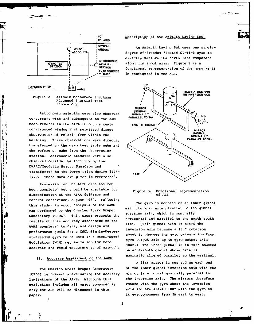
,TO Description of the Azimuth Laying SetPOLARIS
GYRO OPTICAL An Azimuth Laying Set uses one single-y GYRO IWINDOW
,THEODOLITE degree-of-freedom floated GI-Tl-B gyro toSI directly measure the earth rate componentG ASTRONOMIC
GYROTEST~ __AZIMUTH along its input axis. Figure 3 is aSTATION \STATION functional representation of the gyro as it
, REFERENCE
_ _ - CUBE is configured in the ALS.I -
TO PORRO PRISM
SHAFT ALONG SPIN
Figure 2. Azimuth Measurement Scheme OA OR INVERSION AXIS
Advanced Inertial Test 01:Laboratory IA S
MI OAstronomic azimuths were also observed NOMINALLY
concurrent with and subsequent to the AAMS PARALLEL TO SA)
measurements in the AITL through a newly AZIMUTH GIMBAL
constructed window that permitted direct MRO, (NORMALobservation of Polaris from within the NOMINALLYbuilding. These observations were directly P
transferred to the gyro test table cube and
the reference cube from the observation
station. Astronomic azimuths were alsoobserved outside the facility by the
DMAAC/Geodetic Survey Squadron and
transferred to the Porro prism during 1976-1979. These data are given in reference 3. BASE
Processing of the AITL data has not
been completed but should be available for Figure 3. Functional Representation
dissemination at the AIAA Guidance and of ALS
Control Conference, August 1980. Followingthis study, an error analysis of the AAMS The gyro is mounted on an inner gimbalwas performed by the Charles Stark Draper with its spin axis parallel to the gimbal
Laboratory (CSDL). This paper presents the
results of this accuracy assessment of the horizontal and parallel to the north south
AAMS completed to date, and design and line. (This gimbal axis is named the, inversion axis because a 1800 rotation
performance goals for a CSDL Single-Degree-
of-Freedom gyro to be used in a Wheel-Speed about it changes the gyro orientation from
gyro output axis up to gyro output axis
accurate and rapid measurements of azimuth. down.) The inner gimbal is in turn mounted
on an azimuth gimbal whose axis is
II. Accuracy Assessment of the AAMS nominally aligned parallel to the vertical.
A flat mirror is mounted on each end
The Charles Stark Draper Laboratory of the inner gimbal inversion axis with the
(CST)L) is presently evaluating the accuracy mirror face normal nominally parallel to
limitations of the AAMS. Although this the inversion axis. The mirrors therefore
evaluation includes all major components, rotate with the gyro about the inversion
only the ALS will be discussed in this axis and are slewed 1800 with the gyro as
paper. it gyrocompasses from IA east to west.
2I
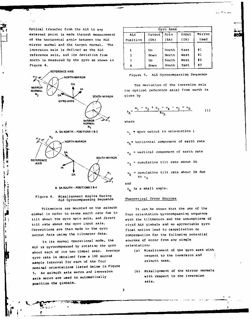
Optical transfer from the ALS to any Gyro Axes _.___
external point is made through measurement ALS Output Spin Input Mirror
of the horizontal angle between the ALS Position (OA) (SA) (IA) Used
mirror normal and the target normal. The
inversion axis is defined as the ALS 1 lip North East #1
reference axis, and its deviation from 2 Down North West #1
north is measured by the gyro as shown in 3 lip South West #2
Figure 4. 4 Down South East #2
REFERENCE AXIS
a 2 NORTHMIRROR Figure 5. ALS Gyrocompasing Sequence
-, N/ X OA The deviation of the inversion axis
MIRROR IANORMAL I I (or optical reference axis) from north is
N2 SA SOUTH MIRROR given by
SGYRO AXES
A 2 + 4h ( )
MIRROR 1 whereNORMAL
N1
A. SA NORTH- POSITIONS 1 & 3 '= gyro output in orientation i
a ,N2'2NORTHMIRROR = horizontal component of earth rate
RSA Sv = vertical component of earth rate
REFEENCESOUTH MIRROR
AXIS = cumulative tilt rate about IA
IA N W= cumulative tilt rate about SA dueOA S to U1 v
and
B. SASOUTH-POSITIONS2&4 th is a small angle.
Figure 4. Misalignment Angles During
ALS Gyrocompassing Sequence Theoretical Error Sources
Tiltmeters are mounted on the azimuth it can be shown that the use of the
gimbal in order to sense earth rate due to four orientation gyrocompassing sequence
tilt about the gyro spin axis, and direct with the tiltmeters and the assumptions of
tilt rate about the gyro input axis. rigid ALS gimbals and no appreciable gyro
Corrections are then made to the gyro float motion lead to cancellation or
output data using the tiltmeter data. compensation for the following potential
In its normal operational mode, the sources of error from any single
A S is qyrocompassed by rotating the gyro orientation:
about each of its two gimbal axes. Average (a) Misaliqnment of the gyro axes with
qyro rate is obtained from a 100 second respect to the inversion and
* sample interval for each of the four azimuth axes.
nominal orientations listed below in Figure
5. An azimuth axis servo and inversion (b) Misalignment of the mirror normals
axis servo are used to automatically with respect to the inversion
position the gimbals. axis.
3-"
-,-.-
'. * - jI
(c) Non-1800 rotation about the (C) Deflection of the inversion axis
vertical (azimuth) axis. gimbal results in a lack of unique
definition of the inversion axis when using(d) Gyro bias and output axis mass the two AS mirrors. This error could he
unbalance, either fixed or time varying dependinq upon
the cause of the gimbal flexure.(e) Tilt and tilt rate as described
above. (d) Gyro float motion with respect to
the gyro case from one ALS orientation to(f) Gyro torque to balance loop scale the next results in time varyinq gyro
factor error, misalignment angles due to multiple gyro
orientations and tilt variations between
Potentially significant error sources orientations. These errors do not
which do not cancel are now coming under necessarily cancel over the four
serious consideration due to present sub- orientation seguence and can lead to a
arc second performance goals. Some of direct error in qyrocompassing.
these soutzes are as follows:
(e) Gyro random errors also lead to a(a) Inversion e.'is servo non- direct error in gyrocompassing. Of
repeatability which leads to a direct error particular importance is the magnitude and
in the estimation of deviation of the____ shape of the gyro drift power spectral
reference axis from north given by density and its relation to the data
tan L processing that is used. The gyro output
4+ + 4)h (2) during each orientation is averaged over a
fixed time interval T. Thus, if the gyrowhere
power spectral density (PSD) contains
, = latitude significant power at frequencies
above -, aliasing can be a serious error
(Oh = inversion axis servo null source. [Aliasing results in rectification
error for the ith of the high frequency nortion of the
orientation as measured in spectrum as an error in the average qyro
the horizontal plane. output.]
Also, the gyro input axis mass (f) Additonal errors due to float
unbalance term will no longer cancel since motion are contributed by the gyro input
it varies with servo nonrepeatability, as axis mass unbalance, the spin axis mass
given by the equation unbalance and two gyro anisoelastic error
terms. Gimbal wobble also results in
E -_gMI (s02 + 2803 + 604) h (3) contributions from the spin axis mass
1 4. h unbalance and the gyro anisoelastic terms.
where MI - gyro input axis mass unbalance
coefficients. Laboratory Evaluation of the AAMS
(b) Inversion axis and azimuth axis The AAMS including the two ALS units
servo dither lead to real time variations is currently being evaluated at CSDL.
in both the rate sensed by the gyro and the Attention is focused on the potential
angular position defined by the optical significant error sources listed above.
axis which can only be dealt with by proper Thus far results have been obtained for
data processing, inversion axis servo repeatability, azimuth
4
I i i
and inversion axis servo dither, and contribute to the final azimuth error after
deflection of the inversion axis shaft, the normal data processing if most of the
An optical cube was mounted on one end low frequency roll-off is due to the servo
of the inversion axis in place of the flat frequency response.
mirror in order to be able to monitor Preliminary results obtained for ALS
rotations of the inversion axis with an #1 show that there may be an inversion
autocollimator. The autocollimator was gimbal axis deflection (i.e., "bent
initially nulled, and subsequent deviations gimbal") of as much as 1 to 2 arc sec with
measured with successive rotations of the warmup of the ALS from room temperature. Of
inversion axis shaft were referenced to the obvious special interest is whether this
initial null. Two estimates of servo deflection is repeatable when the ALS units
repeatability were made. An optimistic are repeatedly cycled again from ambient to
measure assumed that the true servo null operating temperature.
was the average of the deviations from the
initial null, and therefore used the Continued optical testing,
standard deviation of the nean to describe measurements of qyro float motion during
servo repeatability. A conservative the ALS operating sequence, anddetermination of random gyro errors are
measure took the largest difference between
deviations from the initial autocollimator planned for the remainder of the summer.null. In addition, improvements in gyro
technology, tilt measurement andALS unit #1 had a standard deviation compensation, optical transfer of azimuth,
of 0.25 arc sec and a maximum deviation of automation and data processing are planned
1 arc sec. ALS unit #2 had a standard for the next several years. Several of
deviation of 0.97 arc sec and a maximum these areas are discussed in the following
deviation of 3 arc sec. At a latitude of sections.
450, the RSS deviations from Equation (2)
are 0.15 arc sec and 0.52 sec, respectively III. Future Plans for Improving
for ALS #1 and ALS #2 for the uncertainty Instrumentation and Techniques
in aximuth due to inversion axis servo
nonrepeatability. Worst case deviations Traditionally, optical references have
are I arc sec and 3 arc sec, respectively, been used as azimuth holding devices, with
Azimuth and inversion axis servo an implied assumption that only long-term
dither was also monitored by use of azimuth variations with periods of days or
autocollimators. The power spectral longer are significant. However, as
densities for the dither are approximately accuracy demands increase, higher
flat between 0.003 Hz and 0.6 Hz. and then frequency, low amplitude motions of these
roll off at -60 db/decade above 0.6 Hz (At references become of increasing concern.
present it is not known how much of the Portable inertial gyros such as the ALS,
rolloff is due to the autocollimator which employ the technique of
frequency response). Cumulative standard qyrocompassing to minimize systematic
deviations computed from the PSO plots are errors, are presently considered to be the
approximately 0.31 arc sec and 0.17 arc sec most accurate means of tracking the
for the inversion axis and azimuth axis, azimuthal motions of these references.
respectively for ALS #2 and about 0.13 arc Yet, the level of accuracy needed for the
sec for both axes for ALS #1. Recause of DoD systems is fast surpassing even the
the flat shape (i.e., "white noise" capabilities of these inertial
appearance) in the low frequency range and instruments. Thus, the ALS instrument
the rapid roll off above 0.6 Hz, this performance errors previously described,
source of error will not significantly coupled with aging degradation of the GI-
5
Ti-B gyros in the ALS units, are major DF = float bias tc-que
factors to be considered in improving theaccuracy of the entire AAMS. DUNB = float unbalance torque
along each gyro axisImproved Gyro Technology
DCOMP = compliance torque alongCSDL has addressed these limitations each gyro axis
via improved single-degree-of-freedom
(SDOF) gyro technology which eliminates In order to measure azimuth to a
the need for continuous multi-position system goal below one arc second, a rate
gyrocompassing by Wheel-Speed Modulation measurement accuracy for wIA near 0.001
(WSM). WSM is a gyroscope mode of meru is required. (A change in wIA of 0.001
operation in which wheel excitation meru is sensed for an azimuth change of
frequency is varied in order to vary wheel approximately 0.25 arc seconds at mid-US
angular momentum, or H. Performance latitudes.) Thus for typical values of
improvements, such as stable and repeatable error coefficients which range from 10 to
wheel power and reduced sensitivity of 100 meru, 100 to 10 ppm calibration
power with excitation frequency, now enable accuracy is needed, with time stabilities
use of WSM as a more rapid and accurate to the same accuracies. Calibration to
approach to measuring azimuth. Since these accuracies utilizing conventional
azimuth can be determined by WSM in a tumble testing presents a difficult
single gyro position, the mechanical and challenge.
electrical uncertainties inherent in four-
position qyrocompassing are liminated as a to r e n t s rough o e not nreqto rate inputs through WSM does not require
major error source, precise calibration nor stability of the
standard error coefficients. However, itdoes require knowledge of the coefficient
sensitivity to wheel-speed changes as seenUtilizing a SDOF gyro operating in a from Equation (5). During wheel-speed
typical torque rebalance mode, and the gyro modulation, H is varied and the associated
case fixed in space, the rebalance torque change in rebalance torque becomesequals the precession torque plus error AM AD
torques as described in Equation (4). R +DGAH -IA AH
2 where
+ ai(D DG = combined first order gyro errortorques
2+ Z alDuN~ + raj(DcMi (4) + 2
C DF + ai(DUNB)i + ai (DcoMP)i
where Note that second order error torques can
now be neglected since they are very small
a = acceleration vector along each for ADG.
gyro axis For the special case of measuring
azimuth, w IA will equal aw erh ' where a is
MR - rebalance torque the azimuth angle and w erh is the
horizontal component of earth rate.
W1A ' angular rate about the input axis Assuming the angle of the spin axis (H
vector) does not vary within the range of
H a angular momentum of wheel speed change and is orthogonal to the
6
Ko
output axis (OA), the error degrading differentially decay during each sample
accuiracy is AD G/lI{. Thus, if the speed- interval, resulting in unpredictable errorschanqe-sensitive coefficients contained in in the ALS azimuth estimate. Further,
the ADG term are small (as with new gyro differential movement of the two ALSCIdesigns), large uncertainties can be mirrors during a sequence and between
tolerated, continued calibration is not sequences also degrades accuracy.
required, and rate measurement accuracy is By using wheel speed modulation, andnot lost.
thereby eliminating the need for gyro-
As indicated, the ability to compassing, each of these error sources
continuously measure azimuth with WSM is will automatically be greatly reduced. Yet
contingent upon both the magnitude and additional improvements are still
stability of ADG/ H . Obviously, since required. Thus, the performance
gyro rebalance torque is sensitive to speed characteristics of the tiltmeters,
changes, this torque sensitivity will limit autocollimator and inductosyn table have
measurement accuracy if not compensated, been and will continue to be critically
But this sensitivity can be readily examined. Instrument sample rates,
calibrated and if a correction is applied, frequency response characteristics and data
only the stability would then corrupt processing will be matched to critical gyro
accuracy. parameters and new state-of-the-art
technology employed where warranted.
Torque stability, in turn, is a
function of power dissipation and Improved Automation
repeatability with each change in wheel
speed. CSDL test data indicate that these Currently the AAMS is controlled by a
factors are not limitations within the dedicated microprocessor which interfaces
desire,] gyro performance goal below one arc with each major component. The major
second. components (ALS units, autocollimator,
tiltmeters, etc.) are controlled by theirFinally, one must consider optimizing own unique discrete logic. In addition to
the gyro wheel speed change by comparing controlling the experiment this hardware
signal to noise resolution with required acquires all experimental data, digitally
sample time. Once sufficient signal filters analog data, and records all data
resolution is achieved, further reductionon magnetic tape. The system is desiqned
of wheel speed would only increase to be self contained and run unattended.
measurement time due to extended thermal
transients. A second microprocessor is used to
provide a quick field analysis of the
Improved Tilt and Angle Measurements experimental data. This microprocessor can
provide real time multi-channel data plots
Even with improved gyro technology, a and regression analyses of short data
sub-arc second system level accuracy is not segments and other operator-discretionary
realistic without consideration of refined analyses. Complete data reduction and
tilt motion detection and improved azimuth analyses are done through post-processing
on AFGLm
s general purpose computer.transfer. Once again, each of these areas
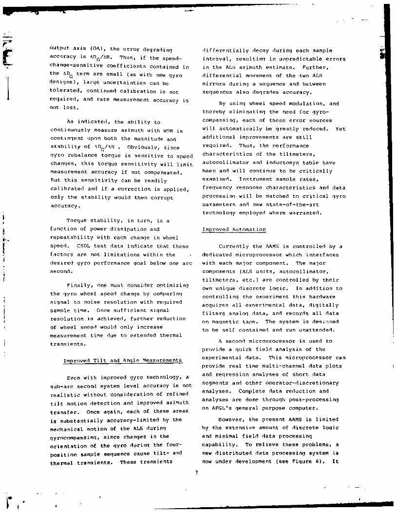
is substantially accuracy-limited by the However, the present AAMS is limited
mechanical motion of the ALS during by the extensive amount of discrete logic
gyrocompassing, since changes in the and minimal field data processing
orientation of the gyro during the four- capability. To relieve these problems, a
position sample sequence cause tilt- and new distributed data processing system is
thermal transients. These transients now under development (see Figure 6). It
7
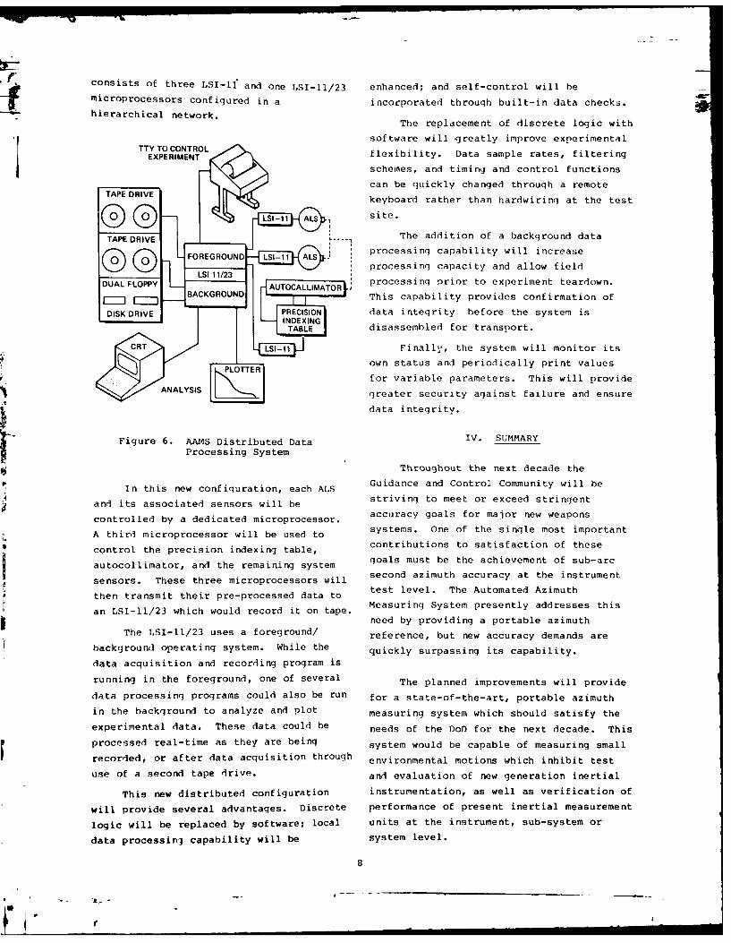
consists of three LSI-Il and one LSI-ll/23 enhanced; and self-control will be
microprocessors configured in a incorporated throuqh built-in data checks.
hierarchi[cal network. The replacement of discrete logic with
software will ,greatly improve experimentalEXPERIMETN flexibility. Data sample rates, filtering
schemes, and timing and control functions
can be quickly changed through a remoteTAPE DRIVE keyboard rather than hardwirinq at the test
LSI-1 ALSsite.
The addition of a background data
OAprocessing capability will increase
e processing capacity and allow field
DUAL FLOPPY AUTOCALLIMATOR processing prior to experiment teardown.BACKGROUND This capability provides confirmation of
DISK DRIVE PRECISION data integrity before the system is
TABLE disassembled for transport.
Finally, the system will monitor its
own status and periodically print values
for variable parameters. This will provide
ANALYSIS -greater security against failure and ensure
data integrity.
Figure 6. AAMS Distributed Data IV. SUMMARYProcessing System
Throughout the next decade the
In this new configuration, each ALS Guidance and Control Community will be
and its associated sensors will be striving to meet tr exteed te
controlled by a dedicated microprocessor, accuracy goals for major new weapons
A third microprocessor will be used to systems. One of the single most important
control the precision indexing table, contributions to satisfaction of these
autocollimator, and the remaining system goals must be the achievement of sub-arcautocoazmutlimatorat handstthen
sensors. These three microprocessors will second azimuth accuracy at the instrumenttest level. The Automated Azimuth
then transmit their pre-processed data toMeasuring System presently addresses this
an LSI-11/23 which would record it on tape.need by providing a portable azimuth
The LSI-1/23 uses a foreground/ reference, but new accuracy demands are
background operating system. While the quickly surpassing its capability.
data acquisition and recording program is
running in the foreground, one of several The planned improvements will provide
data processing programs could also be run for a state-of-the-art, portable azimuth
in the background to analyze and plot measuring system which should satisfy the
experimental data. These data could be needs of the DoD for the next decade. This
processed real-time as they are being system would be capable of measuring small
recorded, or after data acquisition through environmental motions which inhibit test
use of a second tape drive, and evaluation of new generation inertial
This new distributed configuration instrumentation, as well as verification of
will provide several advantages. Discrete performance of present inertial measurement
logic will be replaced by software; local units at the instrument, sub-system or
data processing capability will be system level.
8
€ -
REFERENCFS 3. Roberts, G.E., "MX Laboratory AzimuthData nano Study", Geodynamics Corporation
1. Schnelzer, G.A., G.H. Cabaniss and D. report CA,CDR-0008 (SR380U)-I, prepared forAnthony, "Azimuth Alignment Experiment", HQ. Ballistic Missile Office, Norton AFR,Proceedings, ATAA Guidance and Control March 1980.
Conference, San Diego, California, August1976, AIAA No. 76-1963. 4. Miola, J.A., Measuring Azimuth to One
Arc Second Using Wheel Speed Modulation,2. Shearer, J.A. and W.D. Atwill, Charles Stark Draper Laboratory, Inc.,"Description and Applications for an C-5235, in publication.
Automated Inertial Azimuth Measuring
System", Proceedings, AIAA Guidance and
Control Conference, Palo Alto, California,
August 1978, AIAA No. 78-1251.
9
ImI