analysis and experiments for tendril-type robots
TRANSCRIPT

Clemson UniversityTigerPrints
All Theses Theses
5-2008
Analysis and Experiments for Tendril-Type RobotsLara CowanClemson University, [email protected]
Follow this and additional works at: https://tigerprints.clemson.edu/all_theses
Part of the Robotics Commons
This Thesis is brought to you for free and open access by the Theses at TigerPrints. It has been accepted for inclusion in All Theses by an authorizedadministrator of TigerPrints. For more information, please contact [email protected].
Recommended CitationCowan, Lara, "Analysis and Experiments for Tendril-Type Robots" (2008). All Theses. 325.https://tigerprints.clemson.edu/all_theses/325

i
ANALYSIS AND EXPERIMENTS FOR TENDRIL-TYPE ROBOTS
A Thesis
Presented to
the Graduate School of
Clemson University
In Partial Fulfillment
of the Requirements for the Degree
Master of Science
Computer Engineering
by
Lara Suzanne Cowan
May 2008
Accepted by:
Dr. Ian D. Walker, Committee Chair
Dr. Darren Dawson
Dr. Stan Birchfield

ii
ABSTRACT
New models for the Tendril continuous backbone robot, and other similarly
constructed robots, are introduced and expanded upon in this thesis. The ability of the
application of geometric models to result in more precise control of the Tendril
manipulator is evaluated on a Tendril prototype. We examine key issues underlying the
design and operation of ―soft‖ robots featuring continuous body (―continuum‖) elements.
Inspiration from nature is used to develop new methods of operation for continuum
robots. These new methods of operation are tested in experiments to evaluate their
effectiveness and potential.

iii
DEDICATION
To my parents and teachers, whom I could not have done this without, and the
inspiration of science fiction.

iv
ACKNOWLEDGMENTS
First, I would like to thank Dr. Walker for being a great advisor and always being
there when I had a question. I‘d also like to thank NASA for the opportunity to work with
the Tendril robot. Finally, I would like to thank Matthew Bennink who constructed the
Tendril for Clemson University and started its control program.

v
TABLE OF CONTENTS
Page
TITLE PAGE .................................................................................................................... i
ABSTRACT ..................................................................................................................... ii
DEDICATION ................................................................................................................ iii
ACKNOWLEDGMENTS .............................................................................................. iv
LIST OF FIGURES ....................................................................................................... vii
CHAPTER
I. INTRODUCTION ......................................................................................... 1
II. AZIMUTH, ELEVATION, AND COUPLING COMPENSATION
FOR THE TENDRIL ............................................................................... 7
Tendril Background ................................................................................. 7
Azimuth.................................................................................................. 10
Elevation ................................................................................................ 16
Coupling Compensation......................................................................... 25
Further Considerations ........................................................................... 36
III. THE INTERACTION OF CONTINUOUS AND DISCRETE
ELEMENTS ........................................................................................... 38
Background ............................................................................................ 38
Continuous Structures in Nature ............................................................ 41
Balance/Stability ............................................................................. 41
Exploration/Sensing ........................................................................ 42
Obstacle Removal/Grasping ........................................................... 45
Implications for Soft and Continuum Robots ........................................ 47
Complexity Reduction .................................................................... 47
Design Implications ........................................................................ 49
Summary ................................................................................................ 56
IV. TENDRIL EXPERIMENTS ........................................................................ 57
Stability .................................................................................................. 58
vi
Table of Contents (Continued)
Page
Teleoperation of the Tendril .................................................................. 62
Obstacle Removal .................................................................................. 65
Grasping ................................................................................................. 69
Discussion of Results ............................................................................. 70
V. CONCLUSION ............................................................................................ 72
APPENDIX…. ............................................................................................................... 75
REFERENCES .............................................................................................................. 80

vii
LIST OF FIGURES
Figure Page
1.1 The Tendril Continuum Robot ....................................................................... 3
2.1 Elevation and Azimuth .................................................................................. 9
2.2 Joint1 Encoder Values at 45° Increments ..................................................... 10
2.3 Joint0 Encoder Values at 45° Increments ..................................................... 11
2.4 Azimuth vs Encoder Values at (a) 30°, (b) 45°, (c) 60°,
and (d) 90° Elevation ............................................................................. 12
2.5 Azimuth vs. Encoder Values at 45° Elevation using Formula..................... 14
2.6 Graph of (a) Joint1 and (b) Joint0 Azimuth Encoder
Values for Varying Elevations ............................................................... 15
2.7 Encoder Values vs. Elevation ...................................................................... 17
2.8 Elevation of a Tendril Joint from 0° to 90° ................................................. 18
2.9 Diagram of Tendril and Vectors .................................................................. 19
2.10 Angle Diagrams ........................................................................................... 20
2.11 Elevation vs. Change in Length ................................................................... 21
2.12 Encoder values at Elevation Steps of 5° ...................................................... 22
2.13 Diagram of Lengths ..................................................................................... 23
2.14 Graph of Elevation VS Encoder Values Using Equation 14 ....................... 24
2.15 Using Data from Figure 2.4a ....................................................................... 25
2.16 Compensation .............................................................................................. 28
2.17 Uncompensated and Compensated Tendril ................................................. 30
2.18 Joint1 Compensation when Joint0 is 15° to 90° in 15° Increments .............. 31

viii
List of Figures (Continued)
Figure Page
2.19 Elevation of Joint1 Before Compensation ................................................... 32
2.20 Tendril Bending in Semicircle ..................................................................... 33
2.21 Various Elevations for Joint0 ....................................................................... 34
3.1 Robotic Snake built by Dr. Gavin Miller, Elephant Trunk
Manipulator and Tendril by Clemson University, and
Softbot built by Tufts University ................................................................. 40
3.2 Animals using Prehensile Tails for Balance ................................................ 41
3.3 Climbing Morning Glory Vine .................................................................... 43
3.4 Octopus Opening a Jar with its Arms .......................................................... 44
3.5 Sting Ray, Komodo Dragon tail, and Bullwhip ........................................... 45
3.6 Fictional Snake-Arm Robots (B-9, Sentinel, Doc Ock) .............................. 49
3.7 Real Snake-Arm Robots from OC Robotics ................................................ 50
3.8 Discrete Arm with Continuous Fingers ....................................................... 51
3.9 Flexible Microactuator ................................................................................. 52
3.10 Giraffe Using its Tongue to Extend its Reach ............................................. 52
3.11 Illustrations of a Brittle star and Basket star ................................................ 54
4.1 Basic Tendril Setup ...................................................................................... 58
4.2 Tendril Pulling on Velcro ............................................................................ 59
4.3 Lifting an Obstacle ....................................................................................... 61
4.4 Moving an Obstacle ..................................................................................... 62
4.5 Tendril with Camera on Tip ......................................................................... 63

ix
List of Figures (Continued)
Figure Page
4.6 Environment for the Teleoperation of the Tendril ....................................... 64
4.7 Swatting Ping Pong Ball .............................................................................. 66
4.8 Removal of Balls from Tray ........................................................................ 68
4.9 Tendril Lifting Ring and Placing on Base ................................................... 69
4.10 Tendril Lifting Ring Off of Base ................................................................. 70

1
CHAPTER ONE
INTRODUCTION
The mechanization of industry has created a new ―life-form‖, the robot. Robots
are commonplace in our modern day world. They take many shapes and sizes and
perform a variety of tasks. Robots are present in our factories, in the military, and even
in many homes. Though they are available in a wide range of forms, robot manipulators
fall into three categories: rigid-link, hyper-redundant, and continuum. Rigid-link robots
that are used in industry are usually based upon the structure of the human arm. They
pick and place parts along an assembly line, using a predetermined unchanging pattern of
movement. This is fine for industrial work, but many tasks require a robot to be more
fluid in its design. In the real world, the workspace is not uniform nor is it free of
obstacles. A changing environment requires a robot to be more pliable. A robot that can
conform itself around obstacles has a greater flexibility in its workspace environment.
Hyper-redundant robots, made from multiple small serially connected links, have a
greater range of movement than their rigid-link predecessors [1].
Robotic snakes have been built by a few different groups [1],[2],[3],[4]. Most of
these have been built using multiple discrete links mimicking the backbone of a snake.
These hyper-redundant robots can move in most of the ways snakes can, but they are not
as conformable because of their rigid links. Hyper-redundant robots, like the SnakeBot
[5], represent a bridge between discrete links and continuous elements [6].
As robot construction continues to evolve, soft robots with continuous backbones
are being built. These robots are termed continuum. When comparing robots to nature,

2
rigid-link industrial robots are similar to a human‘s arm and hyper-redundant robots are
like snakes, but continuous robots are more like the arms of an octopus or the trunk of an
elephant. Numerous different types of soft and continuum robots have been proposed.
Continuum robots, such as the Octarm [7] and the Tendril [8],[9], have continuous
backbone sections which can conform around objects [10],[11],[12]. Flexible, functional,
and delicate in their form, these continuum robots could be used for tasks which
traditional hard robots could not adequately perform.
Soft robots can be used for inspecting damage on a space shuttle, snaking through
pipes, or grasping an object with their full body. Continuum robots can be built with a
variety of materials, with the most common form thus far using pneumatic muscles or
being tendon-driven. Soft robots, such as Softbot, are almost gel-like in their form
[13],[14]. However, soft continuum robots are hard to build, model and control [15],[16].
Management of the malleable and compliant properties which form a great part of their
appeal is proving a major obstacle to progress in this emerging field [17].
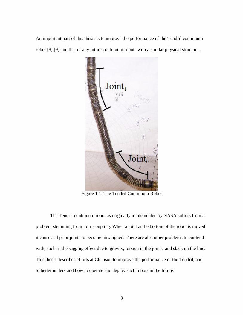
The Tendril is a tendon-driven robot with a body comprised of springs (Fig. 1.1).
Its two joints are made of compression springs with tendons attached to two motors and
pulleys for each joint. Its body is long and thin, emulating the body of a snake or the
tendrils of some plants. NASA originally designed the Tendril for minimally invasive
inspection [9]. A long slender manipulator is potentially useful for probing places that
could not otherwise be reached [9]. In order to accurately position the tip-mounted
camera, the Tendril robot must be able to be precisely controlled to maintain its position.
3
An important part of this thesis is to improve the performance of the Tendril continuum
robot [8],[9] and that of any future continuum robots with a similar physical structure.
Figure 1.1: The Tendril Continuum Robot
The Tendril continuum robot as originally implemented by NASA suffers from a
problem stemming from joint coupling. When a joint at the bottom of the robot is moved
it causes all prior joints to become misaligned. There are also other problems to contend
with, such as the sagging effect due to gravity, torsion in the joints, and slack on the line.
This thesis describes efforts at Clemson to improve the performance of the Tendril, and
to better understand how to operate and deploy such robots in the future.

4
Chapter 2 introduces the notation used in this thesis for the Tendril and equations
governing its movement. The analysis is expanded upon and used to devise a new
solution to the joint coupling problem. Basic geometry and physical properties are used to
derive new models for the elevation and azimuth of the Tendril. The key coupling
problem is studied, and a new approach to decoupling between sections is introduced.
Testing and evaluation on Tendril hardware is described, with resulting recommendations
for future Tendril designs listed. The analysis is expanded to account for a continuous
robot with more than two joints.
Chapter 3 raises basic questions about the inspiration from nature for a continuum
robot. There are numerous animals in nature that can be used as the basis for robots.
Animals perform so many tasks with such simplicity that it would be an oversight to
ignore the designs of nature when constructing a robot. If a robot needs to be built to
perform a specific task, we can look to nature to see if a similar creature already exists.
Industrial robots are shaped like arms, so why not emulate the limbs of other creatures?
There are a variety of continuous limbs in nature. Their shape depends on the task they
must perform. Continuous limbs are present in nature and one of the first to spring to
mind is the tail of a monkey [19]. Tails are very useful limbs with which to balance or
anchor a body while other limbs do fine manipulation [19]. Another example is the
eyestalk of a snail. A snail can bend its eyes this way and that to look around its
environment. If a continuous limb was to be used for grasping, two prominent examples
are the trunk of an elephant [20] or the arms of a cephalopod [21]. An elephant can pick
up large objects, like tree trunks, and deftly maneuver them out of its way. Many people

5
use elephants like living construction equipment. An octopus is even more flexible and
can squeeze its whole body through a space the size of a quarter [22]. Octopuses are such
intelligent invertebrates that they can even remove the lids from jars to get at the tasty
crabs within [23]. Emulating nature can be an interesting way to design a robot.
The construction and control of a robot should depend on the task for which it is
intended. Some tasks can be performed best with rigid-link robots but others would be
more suited to the flexibility of a continuum structure. What combination of continuum
and discrete structures would be best? The analysis in Chapter 3 uses the inspiration of
nature to consider fundamentally new ways to design and control robots. Should a robot
have a continuum arm with a discrete manipulator or a discrete arm with a continuum
manipulator? Should they be controlled in a continuous manner or would a discrete
control work better? The analysis in Chapter 3 seeks to answer those questions and more.
Chapter 4 uses the biological insight gained in Chapter 3 to devise new and novel
strategies for the Tendril robot. The first strategy is illustrated via a stability experiment.
A sticky manipulator added onto the tip of the Tendril is used to grip a patch of Velcro to
hold itself in place. A robot equipped with a continuous tail could use the additional limb
to stabilize its position. The second strategy is to use the Tendril as a sensor, like the eye
stalk of a snail. A small wireless camera mounted on the tip of the Tendril is used to
probe a variety of holes and tunnels. This exploration is NASA‘s main motivation for
Tendril‘s existence, since it could be used to inspect damage to space vehicles. The third
strategy is arguably the most practically useful. Here Tendril is used as an impulsive
manipulator and moves obstacles out of its path. Obstacle removal would be important

6
for robots exploring uninhabitable terrain. Instead of wasting time moving around an
object, it could bat it out of the way instead.
Chapter 5 summarizes the results of the previous chapters and describes future
work that could be done. The decoupling model, biological inspiration, and resulting
operational strategies serve to show that the Tendril is a robot with huge potential. There
remains however much work to be done to improve its performance. The results of this
thesis identify numerous required improvements, along with insight for significantly
improved operation of these kinds of robots in the future.

7
CHAPTER TWO
AZIMUTH, ELEVATION, AND COUPLING COMPENSATION FOR THE TENDRIL
Robots are currently used to perform a fairly wide variety of jobs. Industrial
robots assemble items in factories [24], Roombas vacuum houses [25], and NASA‘s
rovers explore Mars [26]. The jobs robots can do are conceptually virtually endless. If
there is a task that needs to be performed, a robot could, in theory, be built to do it.
Robots automate many tasks that humans used to perform and do them better and faster
as well. ―Hard‖ robots with discrete links are numerous, but soft continuously backboned
robots are less frequent. These ―continuum‖ structures can do many things that rigid
robots cannot. The Tendril is a continuum robot built by NASA to explore [9]. The
Tendril could be used to look in holes to observe any damage. A camera mounted on the
tip could snake around the area to observe the extent of the damage. To do this
effectively, the Tendril system must be operated accurately. If the exact position of the tip
needs to be maintained, then the control of the Tendril‘s position must be accurate. Initial
attempts to achieve good control of the initial Tendril prototype at NASA/Johnson Space
Center proved unsuccessful. Subsequently, parts (identical to those used in the initial
Tendril prototype) were shipped to Clemson, and a second prototype was constructed and
tested in the robotics laboratories here. A new model of the Tendril system will be
presented and tested in this Chapter.
I. Tendril Background
The Tendril is a manipulator whose body is mainly composed of tension springs
with joints made of compression springs. The Tendril‘s motion is controlled by a system

8
of motors and pulleys that pull lines attached at the two joints. The main parts of the
Tendril are shown in Figure 1.1. The top joint is offset from the bottom joint by 45° in a
counter-clockwise rotation. The motor encoder values will be represented by m0, m1, m2,
and m3 for the four motors. Joint1 (top) consists of m0 and m1 while joint0 (tip) uses m2
and m3. The encoder values are the numbers input into the low-level interface to move
the Tendril. The low-level control system checks the encoder values and stops when the
measured value is within error tolerance of the input value, for a given motor. When
calculating the specific encoder values used, some assumptions must be made. It is
assumed that the motors are balanced. This means that if a motor is set to x, then -x will
give the same bend in the opposite direction (―elevation at an azimuth offset by 180°‖).
Another assumption is that the behavior for elevation is the same for both joints. This
constrains the function governing encoder values input to raise a joint to a given
elevation. The two main variables used above are the azimuth and elevation of the joints
(Fig. 2.1). Expressions governing the behavior of these key variables are presented in
Sections 2.1 and 2.2.

9
Figure 2.1: Elevation and Azimuth
The above assumptions and underlying choice of modeling of the Tendril match
those used by NASA in the original prototype. However, there is another key problem not
addressed by NASA that needs to be solved. A coupling error is introduced to the system
by the way joints interact. This coupling between the joints requires a more complex
solution than the simple modeling of the system used by NASA for the first prototype.
When the top joint is moved, there is no coupling error, but when a joint lower down the
line is moved it causes a positioning error with the joints above it. When a tendon
attached to a lower joint is pulled, it compresses the entire Tendril above it instead of
merely the joint it is attached to. The entire upper structure of the Tendril tries to
compress. The more joints there are, the higher the error will be. Gravity accentuates this

10
problem, (though its effects can be eliminated for modeling purposes by laying the
Tendril flat and moving it within a plane orthogonal to the direction of gravity). The
coupling problem, and our work addressing it, is discussed more in depth in Section 2.3.
II. Azimuth
The azimuth is the angle made between the vector directly emanating from the
end of a joint and a fixed reference vector. In the experimental work referenced here, this
reference vector was chosen to be in the plane parallel to the laboratory floor for the top
joint. In this experimental set-up, the azimuth of each joint is measured counter-
clockwise with 0° being parallel to the wall. The motors are attached with an offset of 90°
at each joint. The motors are set to pull at differing azimuths: motor0 is at 135°, motor1 is
at 45°, motor2 is at 0°, and motor3 is at 90°. The azimuth of the joints and the
corresponding encoder values are shown in Figures 2.2 and 2.3 for increments of 45°.
Figure 2.2: Joint0 Encoder Values at 45° Increments

11
Figure 2.3: Joint1 Encoder Values at 45° Increments
The azimuth is used, along with the elevation formula (below), to find the
nominal encoder values to send to the motors. The plot of azimuth vs. encoder values
reveals that the azimuth function is sinusoidal. This makes intuitive sense because the
plot of angle vs. magnitude of a unit vector spinning about the origin will necessarily
result in a sine wave.

12
Figure 2.4: Azimuth vs Encoder Values at (a) 30°, (b) 45°, (c) 60°, and (d) 90° Elevation
A simple expression can be written to approximate the movement of the joint.
First we shall assume that only one joint is moved at a time. If only joint1 is moved, then

13
the encoder values for the joint‘s motors can be calculated by using simple sinusoidal
functions (eqn. 1,2). Since the motors are balanced, the maximum encoder values for the
given elevation are equal and represented as a function of elevation, f(el) (see Section
2.2).
(1)
(2)
If joint0 is moved, then joint1 must compensate to stay in position using formulas
2 and 3. The coupling compensation function comp(el0) is derived in Section 2.3 and
depends on the elevation of joint0.
(3)
(4)
(5)
(6)

14
Figure 2.5: Azimuth vs. Encoder Values at 45° Elevation using Formula
Figure 2.4(a-d) are graphs of the azimuth vs. encoder values at varying elevations.
The tip joint's motors follow a sinusoid quite closely. The top joint's motors approximate
a sinusoid with lessening error as the elevation increases. Figure 2.5 shows the encoder
values derived from equations 3-6 using balanced motors with an elevation of 45°. The
formula does not match the data exactly, mostly due to unmodeled mechanical effects.
The Tendril is not an ideal machine, and is difficult if not impossible to accurately model.
The joint springs have (unmeasureable) torsion and can twist out of place. The encoders
are not centered nor balanced. A more precise model to calculate encoder performance
can be found by using an equation for an off-center ellipse instead of a centered circle to

15
model the azimuth movement. A mathematically perfect Tendril would feature a circle
for the comparison of the motors, but the actual Tendril's plot tends to square out as the
elevation increases as can be seen from Figure 2.6. As the elevation increases, the top
joint stays centered around the same rough spot. The center for the bottom joint seems to
move off to the right at increasing elevations after 60°.
Figure 2.6: Graph of (a) Joint1 and (b) Joint0 Azimuth Encoder Values for Varying
Elevations
These graphs show that the tip joint is better behaved than the top joint. This
makes intuitive sense since the tip joint does not have the extra string running through it
as the top joint does. Using more detailed models can fix some - but as we shall see, not
all - of the problems. The maximum encoder values follow a slight ellipse that squares
out as the elevation increases. This is likely due to purely mechanical measures used (and

16
needed) to tighten the Tendril to remove the slack from the lines. When the Tendril is in
the initial position, with both joint straight down, the lines must be drawn in for a small
time to remove the slack before it will move. Similarly, as the elevation approaches 90°,
it is harder for the lines to be drawn in by the pulleys. This means that the Tendril slows
slightly and needs a higher encoder value to reach its desired position. A nonlinear
formula using both azimuth and elevation is required to reflect this.
III. Elevation
The elevation of the Tendril is the angle the (vector emanating directly from the
backbone at the) joint makes relative to its straight (vertical) position. In order to
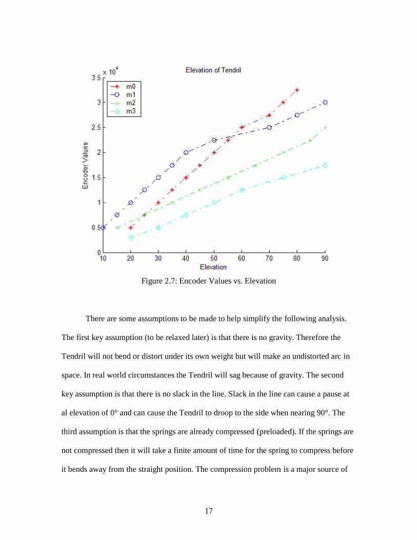
determine an expression for the elevation, some experimental values were observed.
Figure 2.7 shows the encoder values for various elevations that were graphed in Matlab.
The data indicates that the function f(el) follows a linear function up to a certain point
where the mechanical aspects of the Tendril cause it to become nonlinear. The tip joint
elevation is a more linear function than the top joint. The deviation could be due to
compression of the springs or slack in the line.
17
Figure 2.7: Encoder Values vs. Elevation
There are some assumptions to be made to help simplify the following analysis.
The first key assumption (to be relaxed later) is that there is no gravity. Therefore the
Tendril will not bend or distort under its own weight but will make an undistorted arc in
space. In real world circumstances the Tendril will sag because of gravity. The second
key assumption is that there is no slack in the line. Slack in the line can cause a pause at
al elevation of 0° and can cause the Tendril to droop to the side when nearing 90°. The
third assumption is that the springs are already compressed (preloaded). If the springs are
not compressed then it will take a finite amount of time for the spring to compress before
it bends away from the straight position. The compression problem is a major source of

18
difficulty in the design, and could be avoided in alternate designs by using tension
springs for the joints since they are already compressed.
The initial position of the Tendril is hanging straight down with the elevation set
to 0°. The maximum advisable elevation is 90° but the Tendril can bend past that, up to
approximately 135°. Figure 2.8 shows the elevation of the Tendril for a variety of angles.
Figure 2.9 is a diagram of the Tendril showing new variables for elevation.
Figure 2.8: Elevation of a Tendril Joint from 0° to 90°

19
Figure 2.9: Diagram of Tendril and Vectors
In Figure 2.9, the new variables are introduced to describe the elevation of the
Tendril. The lengths of the Tendril joints and connecting sections are Lj and Lc
respectively. These are assumed to be equal for each joint and section. The vectors Vn1
and Vn0 are used to describe the direction of the top node of the joint. The vectors Vj1 and
Vj0 are used to describe the direction of the bottom node of the joint. This is used to
determine the angle that the joint is bent. The angles of elevation of the joints are el1 and
el0. These are the angles between the top and bottom node vectors for each joint as seen
in Figure 2.9.

20
Figure 2.10: Angle Diagrams
The angle of elevation (el) is equal to the arc angle (θc) formed by the Tendril
joint n (Fig. 2.10). The chord from Vn to Vj is approximately equal to the length (Lcrd) of
the taut tendon being pulled. The difference between the actual length of the Tendril (Lj)
and the taut chord is the length (ΔL) that the tendon that has been pulled. This value can
be used to find f(el), the maximum encoder value for the specific joint elevation.
(7)
(8)
(9)
(10)

21
Figure 2.11: Elevation vs. Change in Length
The expression for ΔL can be used to find the maximum encoder value required
for a certain local elevation (Fig. 2.11). The Tendril has an Lj of 7cm and an Lc of 5cm.
The conversion from cm to encoder steps is used to change equation 9 into a formula that
gives out encoder steps as seen in equation 10. The conversion number (cm2enc) was
found to be 50000 encoder steps per cm for Joint1 and 25000 encoder steps per cm for
joint0. The disparity in value can be attributed to the slack in the line for joint1. These
values will change when the Tendril setup is altered or the rate is changed. Figure 2.12
shows a plot of elevation and encoder values measured from the Tendril.

22
Figure 2.12: Encoder values at Elevation Steps of 5°
The encoder values are not the same as those predicted. Since the Tendril's motors
are not balanced, the tightness of the tendons in not equal and it takes some time for the
joint to move at first. When looking at the data for the first 5°, it is evident that the
Tendril must take some initial steps to draw in the slack before it can start moving.
Equation 10 is not precise enough so another expression to compute the maximum
encoder values needs to be derived. A better way to compute the difference in the length
of the tendon is to calculate the difference between the inner length and the center of the
Tendril. Equation 14 shows the new expression for finding f(el). This is more accurate
than the stylized representation in Figure 2.10 since it more accurately describes the

23
change in length. Figure 2.13 defines the variables used in the equations, with el in
degrees.
Figure 2.13: Diagram of Lengths
(11)
(12)
(13)
in encoder steps (14)

24
Figure 2.14: Graph of Elevation VS Encoder Values Using Equation 14

25
Figure 2.15: Using Data from Figure 2.4a
The results from equation 14 are more balanced than equation 10. In Figure 2.14,
the two motor encoder values more closely match the expected values for their joint. In
Figure 2.15, the elevation data from Figure 2.4a is graphed against equation 14 and the
results look closer. As the joints approach 90°, the springs begin to twist more as they
bunch up. This causes some deviation as the elevation increases.
IV. Coupling Compensation
The key coupling problem, not addressed in the above models, occurs when the
movement of one joint affects another joint‘s position. When a joint is moved it causes all
joints higher than itself to become misaligned due to the interaction between joints.
26
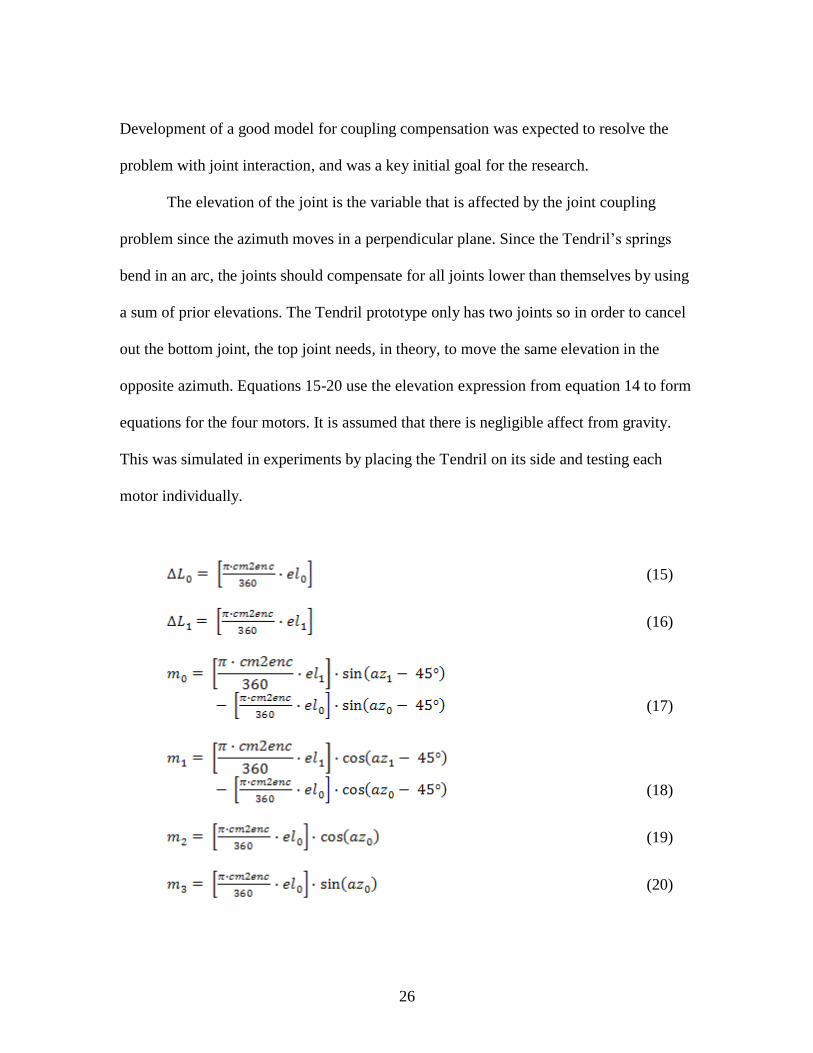
Development of a good model for coupling compensation was expected to resolve the
problem with joint interaction, and was a key initial goal for the research.
The elevation of the joint is the variable that is affected by the joint coupling
problem since the azimuth moves in a perpendicular plane. Since the Tendril‘s springs
bend in an arc, the joints should compensate for all joints lower than themselves by using
a sum of prior elevations. The Tendril prototype only has two joints so in order to cancel
out the bottom joint, the top joint needs, in theory, to move the same elevation in the
opposite azimuth. Equations 15-20 use the elevation expression from equation 14 to form
equations for the four motors. It is assumed that there is negligible affect from gravity.
This was simulated in experiments by placing the Tendril on its side and testing each
motor individually.
(15)
(16)
(17)
(18)
(19)
(20)

27
Adding more joints to the Tendril will increase its degrees of freedom and allow it
to reach more places. If further joints are added, then formulas 21-33 can be used to find
the encoder values. It is assumed that cm2enc is the same for all joints. For each joint 0 to
n and motor x, the real encoder value (mRnx) will be calculated using the desired value
(mDnx) and the previous joint's real value (mRn-1x). The function f(eln) is the elevation of
joint n. The elevation equation, f, should work for every joint. Each of the n joints has 2
motors. The function gx(azn) is the azimuth of motor x and depends on the orientation of
the tendons for each motor. Equations 22-25 show the g function for motors 0 to 3.
Equations 26-29 are a simplified version of equations 17-20 using equations 21-25. The
most important aspect of this new model is equation 33 which describes how to obtain
the encoder values for all motors using a summation of desired values.
(21)
The motor specific azimuth equations are as follows:
(22)
(23)
(24)
(25)
The individual equations for the motors are below.
(26)
(27)

28
(28)
(29)
If more than two joints are present, equations 26-29 become the following:
(30)
(31)
(32)
(33)
Figure 2.16: Compensation

29
The next step is to include gravity. The connecting sections (Lc) are assumed to be
too stiff to bend, but they do sag because of gravity. As you travel up the Tendril's joints,
each node will be affected by gravity more than its predecessor. Since the Tendril is in
effect one long spring, it can be assumed that the whole Tendril attempts to bend when
the lowest joint is elevated. A similar effect can be seen when placing a Slinky on a table
and bending it in a circle. Since the sections bend equally, all prior joints should bend by
the desired angle of the moving joint. This is not true in practice because of gravity, so
the model needs to be expanded to include gravity. Figure 2.17 shows a photo of the
Tendril coupling problem. After developing the analysis further, the next step is to move
both joints and evaluate the performance of the model.

30
Figure 2.17: Uncompensated and Compensated Tendril

31
Figure 2.18: Joint1 Compensation when Joint0 is 15° to 90° in 15° Increments
The compensation does not follow the circular pattern as the azimuth changes.
This is because of the unbalanced and off-center motors as well as difficulties arising
from remaining unmodeled mechanical effects. The plot of the encoder values for the
motors shows that when Joint0 is moved, the compensating movement of Joint1 is an
irregular shape (Fig. 2.18). The value of m1 is larger than m0, which results in an ellipse.
The center is near (m0,m1) = (1000,2000) at first but it drifts towards (5000,2500) when

32
the Joint0 elevation is 90°. To fix this the Tendril would need to be restrung with all
tendons having equal tautness and starting perfectly centered. Another problem is that the
angle that Joint1 is off by changes as the azimuth changes (Fig. 2.19). The angle is
skewed because the off-center motors alter the parameters. The angle should, in theory,
be equal across the azimuth.
Figure 2.19: Elevation of Joint1 Before Compensation
In order to check the elevation without gravity, the Tendril was restrung and
shortened. The extra sections above the joints as well as the connecting section were
removed. This leaves one connecting section and the two joints. This assembly was
placed on a flat surface and the tendons were manipulated to see how it would act without

33
gravity (Fig. 2.20). Since the motion is within a plane only motor 2 is manipulated.
Ignoring slight defects because of friction, the Tendril bent like the bottom image of
Figure 2.16. The top joint bends the same angle as the bottom joint. Figure 2.20 shows
three positions of the Tendril at around 0°, 45° and 90°. The top joint bends at the same
angle. Both joints together form a partial circle, demonstrating constant curvature.
Figure 2.20: Tendril Bending in Semicircle
A red arc has been drawn over the Tendril in Figure 2.20 to show that both joints
are bending equally. The tendon for motor 2 is the only one being manipulated in the two

34
figures. When it is pulled, the whole Tendril bends in a continuous arc. Figure 2.21 has
images of the tip joint bending from 0° to 90°. Both joints have the same elevation, which
proves that the top joint bends the same elevation as the bottom joint. Therefore
compensation should be as simple as bending the top joint in the opposite direction as
described in formulas 21-33.
Figure 2.21: Various Elevations for Joint0

35
The control system for the Tendril robot uses an interface called Qmotor to
directly control the motors. When the basic control program is loaded, the interface
consists of a window in which encoder values may be entered. The motors will run until
the encoder value is equal to the entered value with a certain allowed error. The encoders
are not precise, so the values were usually changed by at least 250 steps to see any
movement of the Tendril. A more advanced program was created to try and fix the
coupling error. Data points were gathered for elevation of the four motors. The program
used these values to create polynomial expressions for the elevation of each motor. It did
not work very well for many reasons. The biggest reason was that every time something
changed in the Tendril (starting encoder values, compression, slack, etc.) the data would
have to be gathered again in a time-consuming process. This lack of experimental
repeatability was why the fundamental model for the Tendril was made. If a model is
made using equations 21-29, the Tendril‘s performance should become better. However,
even with the new model there are other factors that cause adverse effects with the
Tendril. The effects of gravity, slack, compression, torsion, and unbalanced motors can
be partially overcome by mechanical means. The compression, slack, and balance issues
can be fixed by making sure that the springs are initially compressed, the system is strung
to eliminate slack, and the motors can be meticulously balanced. To remove the effects of
gravity, the Tendril can be placed in a plane so that it moves horizontally (Fig. 2.21), but
then only one motor can be moved (the one attached parallel to the surface the Tendril

36
lies on). There are still many ways to improve the model because in practice the good
aspects of the new model are overcome by the bad effects of the unmodeled system.
V. Further Considerations
The Tendril in concept is a versatile creation that has many potential uses. Models
to represent the movement of the Tendril need to be accurate if it is to be used for fine
positioning, for example to position a camera accurately. This is true for all manipulators
and is a particular and ongoing challenge for continuum manipulators [7]. However, our
research suggests that the specific design of Tendril makes it particularly difficult to
control precisely. Our overall recommendation (see Chapter 5) is that the best approach
to an improved Tendril-type robot would be to significantly alter the current Tendril
design to reduce or remove many of the mechanical imprecisions rather than
concentrating on improved models and controllers for the current hardware design.
However, the analysis in this chapter has produced useful insight and
understanding into the basic operation of future Tendril-type manipulators. The azimuth
and elevation of the basic Tendril design can be modeled using simple expressions. The
coupling compensation requires a more complex approach and currently does not take
gravity into affect. Gravity will cause nonlinearities in the system because as higher joints
move, the longer lower portion of the tendril will cause sag. Future experiments could be
conducted in water to lessen the affect of gravity (though in this case additional
hydrodynamic effects would be present).
In the current version of the hardware however, there are numerous situations
caused by mechanical issues that also need to be resolved, such as the hanging at an

37
elevation of zero. When the Tendril passes through zero elevation, the slack must be
taken up before it can move in the opposite direction which leads to a time delay and an
error in the encoder reading. One potential solution is to increase the rate of movement as
the elevation approaches zero while decreasing the rate as the elevation increases.
Another solution is to add tension springs on each of the lines to eliminate the slack.
There are a few things to consider when running experiments with the Tendril.
The best way to test the azimuth formulas would be at an elevation of 45° since slack and
other nonlinearities can be ignored safely. The elevation formulas should be tested at the
azimuth angles that the tendons attach at. Further refining of the models should take
gravity into account since it pulls on the connecting sections and affects the angle of
elevation. The lower joint should be moved before the top joint so that its movement
doesn't misalign the top joint. The top joint should be moved slower than the bottom joint
because it has a longer arm. Software compensation for the off-center and unbalanced
motors could improve performance. The above analysis does not take dynamic effects
into consideration. Once the basic laws of motion are known, other approaches may be
considered to help the system approach real-world situations.
The modeling and control requirements can be less specific if Tendril is to be used
to move in a general direction rather than a specific location. This aspect is considered in
the following Chapters.

38
CHAPTER THREE
THE INTERACTION OF CONTINUOUS AND DISCRETE ELEMENTS
I. Background
Robot designs can be made by adapting physical structures from nature. Most
modern industrial robots are (human) arm-inspired mechanisms with serially arranged
discrete rigid links. This is fine for industrial work where the workspace is predefined
and structured. However, other robots will have to move about or interact with the
unstructured natural world and need to adopt more general ways of operation. The
Tendril robot is modeled after natural elements such as octopus arms and plant tendrils.
If we look at continuum structures in nature, we can observe how they are operated and
adapt their motions to be used with continuum robots. The motions of natural
continuum structures seem complex at first, but can be simplified when broken down
into key patterns.
A robot that must interact with the natural world needs to be able to solve the
same problems that animals do. Animals come in many shapes and sizes with widely
varying specialized limbs suited to their particular everyday tasks. However, most
robots are built according to ―general-purpose‖ specifications with little attention to
what they will ultimately be used for. The rigid structures of traditional rigid-link robots
limit their ability to maneuver in tight spaces and congested environments, and to adapt
to variations in their environmental contact conditions.
In response to the desire to improve the adaptability and versatility of robots,
there has recently been much interest and research in ―soft‖ robots [17]. In particular,

39
numerous research groups are investigating robots based on continuous body
―continuum‖ structures. Motivation for this work often comes from nature. If the body
of a robot was soft and/or continuously bendable then it might emulate a snake or an eel
with an undulating locomotion [27]. A slithering robot could navigate through a variety
of terrains. Another option is for a continuous manipulator. A continuum manipulator
could be similar to a prehensile tail, an elephant's trunk, or an octopus's arm.
Numerous different types of soft and continuum robots have been proposed.
Robotic snakes have been built by a few different groups [1],[2],[3],[4]. These have
almost all been built using multiple discrete links. These hyper-redundant robots can
move in most of the ways snakes can, but they are not as conformable. Hyper-redundant
robots, like the SnakeBot [5], represent a bridge between discrete links and continuous
elements [6].
Continuum robots, such as the Octarm [7] and the Tendril [8],[9] (Fig. 3.1), have
continuous backbone sections which can conform around objects [10],[11],[12]. Soft
robots, such as Softbot, are almost gel-like in their form [13],[14]. However, soft
continuum robots are hard to build, model and control [15],[16]. Management of the
malleable and compliant properties which form a great part of their appeal is proving a
major obstacle to progress in this emerging field [17].

40
Figure 3.1: Robotic Snake built by Dr. Gavin Miller, Elephant Trunk Manipulator and
Tendril by Clemson University, and Softbot built by Tufts University
There is an inherent tradeoff between continuous and discrete elements. For
example, continuum structures can conform to their surroundings while discrete rigid
links aid precise positioning. A combination of the two might yield a strong yet
malleable form. Interestingly, continuum structures in nature seem to synergize their
activities with various kinds of discrete elements, as discussed in the following section.
With this in mind, we argue in Section 3.3 that with a judicious mixture of
continuous/soft and discrete/hard elements, robots can be made to perform many tasks.
A wider implication is that robots should be built with more consideration for the future
tasks they will perform. We conclude that the structure of soft and continuum robots
41
should depend strongly on the task the robots will be used for and the application
environment [18].
II. Continuous Structures in Nature
Animals in nature have a wide variety of continuum structures. Arms, tails,
tentacles, and various other appendages all have a key function that they perform for the
animal. In the following, we classify these functions into three main classes.
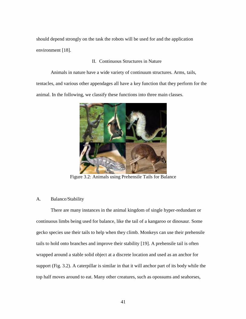
Figure 3.2: Animals using Prehensile Tails for Balance
A. Balance/Stability
There are many instances in the animal kingdom of single hyper-redundant or
continuous limbs being used for balance, like the tail of a kangaroo or dinosaur. Some
gecko species use their tails to help when they climb. Monkeys can use their prehensile
tails to hold onto branches and improve their stability [19]. A prehensile tail is often
wrapped around a stable solid object at a discrete location and used as an anchor for
support (Fig. 3.2). A caterpillar is similar in that it will anchor part of its body while the
top half moves around to eat. Many other creatures, such as opossums and seahorses,

42
have prehensile tails. The tails can be used to balance on land, in the trees, or under the
sea. In this sense natural continuum structures compensate for the complexity inherent in
their ―softness‖ by essentially environmentally grounding themselves at discrete body
locations, typically coupling with hard environmental elements. By contrast, when an
animal's tail is used for balance when running, it is typically discretely controlled, (or
controlled by varying a finite set of discrete elements) compensating for its complexity
by simple cyclical movements, being swung out behind to counter the animal's
movements. Soft continuum robots could clearly benefit from adopting similar strategies.
B. Exploration/Sensing
Exploration and sensing are other key functions of natural continuum limbs.
Snakes have many different ways to slither. (Generally slithering refers to snakes but also
describes the movement of slugs and earthworms.) The four slithering types are lateral
undulation, rectilinear locomotion, concertina locomotion, and sidewinding [4]. The type
of motion a snake uses depends on its environment. Lateral undulation is the main way
snakes move by undulating side to side [4]. Rectilinear locomotion is how large pythons
and anacondas move using their belly scales [4]. Concertina movement is how snakes
climb or move in limited surroundings such as tunnels [4]. Sidewinding is used to move
in the desert over loose sand [4]. Under water, eels and sea snakes can wind their way
through holes in the coral to find food.
Often natural continuum elements are used as both sensors and effectors. Garden
eels, brittle stars, and basket stars all sway in the ocean current to detect food. When a
brittle star senses food, it will fling its arm out in the general direction of the food. Then it

43
will coil an arm around it and bring the food to its central mouth. Once again, this
flinging is not continuously controlled, but is discrete (in the sense introduced in the
previous section) since the arm merely unfurls in the needed direction. A similar pattern
of discrete control, and combination of sensing and exploration, are adopted by plants
such as vines (Fig. 3.3).
Figure 3.3: Climbing Morning Glory Vine [28]
Alternative natural sensing continuum appendages are whiskers and antennae.
Many animals have whiskers to help with their spatial awareness. A catfish's whiskers are
used to check the muck at the bottom of a river for food. The tentacles on a star-nosed
mole are very sensitive, for example the animals can even smell underwater [29]. A robot
could use a continuum appendage with sensors to probe places its main body cannot
reach. This would be very useful in exploration of hazardous areas.

44
Figure 3.4: Octopus Opening a Jar with its Arms [30]
Here once again, it appears the natural soft/continuum elements are seldom used
in isolation of discrete or hard elements. For example, an octopus will wrap its arm
around an object but uses its suckers, located discretely along the arm, for fine sensing
and manipulation (Fig. 3.4). Millipedes have a hyper-redundant body studded with
numerous discretely positioned legs. Their bodies will conform to the obstacles that they
crawl over while using the fine movements of their legs for adjustments. Large anacondas
use their belly scales to crawl forward silently when stalking prey [4]. These three
creatures all use a combination of soft and hard(er) elements. These hybrid
continuum/discrete structures incorporate discrete elements for fine resolution, using
discrete parts for fine work and their continuum anatomy for general purpose positioning.

45
Figure 3.5: Sting Ray, Komodo Dragon tail, and Bullwhip
C. Obstacle Removal/Grasping
Another way to use a continuum limb is to use it to remove obstructions and
rapidly grasp/manipulate the environment. A whip-like structure can be flicked out to
move an obstacle from the animal's path. The movement does not have to be particularly
accurate since it often just needs to be cast in the correct general direction. Many animals
use their tails as weapons. Komodo dragons will whip enemies and so will sting rays
(Fig. 3.5). If it was considered as a weapons system, a scorpion's tail would make an
interesting model. Continuous natural appendages are also used as weapons. The
tentacles of a squid are used to dart out in the direction of prey [31]. Similarly, a brittle
star can fling its arms in the general direction of food and then draw the arm in to feed
itself.
Octopus arms, which are formidable weapons as well as effective manipulators,
appear to be similarly discretely directed in the direction of objects of interest rather than

46
having their shapes closely controlled [21]. Brittle stars manipulate objects in a similar
manner as octopuses, but unlike octopuses the brittle star does not have strong suction
cups on its arms. Each arm is like a snake's tail and can be used to wrap around objects.
They can slither or crawl depending on the terrain. Their arms are quite dexterous and
can be used to grab food and move it to the star's central mouth. Elephants also simplify
control of their trunks by moving them within a plane oriented towards objects they
desire to grasp [20].
Humans can also be very effective when augmented with continuum tools. Whips,
lassos, and chains are all flexible tools that can be used in a variety of ways. In the
movies, Indiana Jones has used his whip to swing across gaps [32]. If a robot could do
this, then it could transport itself to places it could otherwise never reach, or at least get
there quicker. Ropes can be made into lassos to loop around objects. Cowboys use lassos
to capture errant steers. A robot could potentially use a lasso to hook rock outcroppings to
pull itself up a cliff. A grappling hook is a strongly related alternative.
A common element in all the above examples is once again discrete control, with
the problem of close control of all degrees of freedom in the continuum structure
sidestepped by making simplified motions (controlled by a discrete set of variables) in
specific directions. In many cases, only the direction and speed need to be directly
controlled. A continuum limb could similarly be used swiftly to fling obstacles out of the
robot's path, or form quick but effective curling grasps.

47
III. Implications for Soft and Continuum Robots
The examples from nature in the previous section motivate a new look at soft
continuum robots. Up to this point, most development has been motivated by the desire to
create ―fully soft‖ continuum robot bodies with no hard or discrete elements, and to
precisely control their shape through the continuum of possibilities, independent of their
environment. However, it seems clear that many natural soft and continuum elements are
successful precisely by incorporating discrete elements, simplifying their movements, or
interacting in a way very specific to their environment. The key in all cases we have
reviewed is complexity reduction, which leads to strong implications for robot
development. Each of these issues is investigated in the following subsections.
A. Complexity Reduction
A key goal for soft continuum structures is adaptability: compliance to
environmental constraints via an enhanced (essentially infinite dimensional)
configuration- or shape-space. In robotics, almost all efforts so far have tried to achieve
this via soft compliant bodies in controlled continuum contact with their environment.
(The two main types of continuum manipulator today are tendon-driven [6],[33],[34] or
pneumatically [11],[34],[35],[36] controlled.) However, the resulting decision space (and
its requirements for sensing and planning) is vast. A key simplifying observation from the
natural world is that in nature, soft continuum limbs are used mostly for approximate
positioning, strongly exploiting discrete elements in their structure, operation, or their
environment to simplify and resolve their operation. In all cases this allows complexity
reduction: environmental contact and fine manipulation details are handled by discrete

48
scales, legs, or suckers; the movement space is restricted to a given direction or plane, as
in the movements of octopus arms and elephant trunks, or dynamic balancing of tails;
imprecision due to environmental forces is alleviated via stabilization using tails,
anchors, or tongues. All these concepts could be exploited in novel robotic counterparts.
Another issue which appears to have been rarely considered as a major issue in
robotics, but which appears critical in nature, is that of the underlying nature of control.
Continuous control (regulation of the system to an arbitrary shape throughout its
workspace) enables precise operation. Continuous control in the above sense is the most
commonly used form of control in conventional rigid link robots. This allows the control
system to compensate for (indeed, take advantage of) the simplicity of the discrete rigid
link structure to achieve the precise positioning desired in structured applications such as
manufacturing. However, effective continuous control of continuum robotic structures is
proving extremely difficult to achieve [7],[8]. The increased complexity in continuum
structures is hard to either model well, or to provide sufficient actuator inputs for, to
enable consistent control.
Nature however suggests an alternative approach to complexity reduction in
control. If a continuous manipulator is controlled discretely (restricting the allowable
shapes of the system to a finite set, or a shape set defined by a finite set of inputs) then it
will be much easier to control. Clearly many, if not most, continuum structures in nature
are controlled in a discrete (as defined above) manner, as discussed in Section 3.2. Notice
that in this case the compliance inherent in the continuum structure allows the system to
adapt to compensate for the simplicity of the control. The concept of central pattern

49
generators has been used to define the shapes and simplify the control of some snake-like
robots [27]. An extension of these ideas to the wider class of continuum robots could
enable practical control of behaviors similar to octopus arm or elephant trunk
manipulation. Binary control (enabling ―whip-like‖ movements similar to those discussed
in Section 3.2.3) has corresponding potential for continuous manipulators in dynamic
tasks.
B. Design Implications
A common theme in the above discussion is the effectiveness of the combination
of continuous and discrete elements. One direct way to achieve this synergy is by
incorporating both types of structure on an overall robot design, a hybrid
continuum/discrete robot.
Figure 3.6: Fictional Snake-Arm Robots
B-9 (top left), Sentinel (bottom left), and Doc Ock (right)

50
Figure 3.7: Real Snake-Arm Robots from OC Robotics [33]
Some hybrid continuum/discrete robot designs have previously been considered.
One possibility is to have a continuous arm and simple gripper, like the trunk of an
elephant which can pick up a peanut with its finger-like projections. A robot with a
continuous arm and discrete gripper is generally called a snake-arm robot. There are
numerous examples of snake-arm robots in science fiction: Bender from Futurama, Doc
Ock from the Spiderman comics, the Sentinels from the Matrix, B-9 from Lost in Space,
and many more (Fig. 3.6). (Several real snake-arm robots are discrete, using many joints
to become hyper-redundant [6].) Snake-arm robots are used in the nuclear industry and
for robotic surgery [33],[37] (Fig. 3.7). The advantage of having a continuous arm with a
discrete gripper is that it would be like having a tentacle with a hand on its end, providing
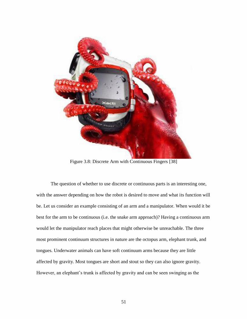
impressive maneuverability with a simple, if not particularly dexterous, grasp (Fig. 3.8).
51
Figure 3.8: Discrete Arm with Continuous Fingers [38]
The question of whether to use discrete or continuous parts is an interesting one,
with the answer depending on how the robot is desired to move and what its function will
be. Let us consider an example consisting of an arm and a manipulator. When would it be
best for the arm to be continuous (i.e. the snake arm approach)? Having a continuous arm
would let the manipulator reach places that might otherwise be unreachable. The three
most prominent continuum structures in nature are the octopus arm, elephant trunk, and
tongues. Underwater animals can have soft continuum arms because they are little
affected by gravity. Most tongues are short and stout so they can also ignore gravity.
However, an elephant‘s trunk is affected by gravity and can be seen swinging as the

52
elephant moves its head from side to side. Adding a discrete gripper onto the end of a
continuum trunk would cause an even greater sag in the robot.
Figure 3.9: Flexible Microactuator [12]
Figure 3.10: Giraffe Using its Tongue to Extend its Reach
An interesting alternative design approach would be to use a serial discrete link
arm and a continuous end effector. This model is less frequently explored than the snake-
arm robots, even in fiction. The giraffe is a natural example. The concept can be thought
of as a discretely built neck with a continuous tongue as a manipulator. It could use its
prehensile tongue to reach places it cannot fit its neck into (Fig. 3.10). Unlike the giraffe's
tongue, most robotics end effectors are in the form of hands or simple grippers. One
example of a hand with continuum elements is the AMADEUS dexterous underwater
gripper [17]. The flexible microactuator built by the Toshiba Corporation is much smaller

53
and could be used for more delicate tasks [12] (Fig. 3.9). This type of robot manipulator
would be like having an octopus for a hand. It would be able to manipulate objects
dexterously and do things that current discrete link manipulators can't. One issue with the
manipulator is how many fingers it should have and how many joints for each. Four
fingers is usually enough to manipulate objects in 3D. As with a continuous arm,
continuous fingers would have sagging and torsion issues. However, this would be less
than for a continuum trunk, and the continuum end effector could compensate for gravity
and/or changes in the environment such as the movement of its goal, just like a giraffe's
tongue can move to catch leaves blown by the wind. There are few examples of a discrete
arm with a continuous end effector in nature. However, there are also few examples of
the wheel and yet it is one of humanity's most useful inventions. Roboticists should look
to nature for inspiration and as well as their imagination.
A third alternative design would be a non-serial hybrid continuum/discrete
structure. These structures might be ideal for fine manipulation. One natural model for a
continuous end effector is the basket star, which has similarities with the brittle star (Fig.
3.11). Rather than a brittle star's five limbs, the basket star has a fractal-like pattern of
tentacles. It is almost tree-like in its form. A basket star would make a great manipulator
if you could control it.

54
Figure 3.11: Illustrations of a Brittle star and Basket star [39]
A key question raised by the earlier discussion is how motions for soft continuum
robots should be planned and controlled. Motivated by the examples from nature
reviewed here, we argue that simplifications should be sought where possible, as
discussed in the previous subsection. The strategy of restricting and controlling
movements to a plane is appealing and clearly successful for many animals, and we
believe likely to be most practical for continuum robotic elements. For hybrid
continuous/discrete robots, it would appear to be best for the discrete part of the robot to
be controlled continuously (and vice versa) so that the discrete part is concerned with
precision, and the continuum part with more global environmental accommodation. For
example, the fractal-like pattern of the basket star end effector design would be hard to
control continuously so discrete control of the continuum elements would be most
appropriate.

55
Additionally, it seems clear that the structure of these new forms of robots with
soft continuum elements robot should be dependent on the environment they will operate
in. The traditional approach of building general-purpose robots has only been partially
successful – while traditional robots are used for a variety of tasks in structured
environments, typically those environments have been heavily engineered to fit the robots
capabilities. Therefore robots have not significantly penetrated the inherently
unstructured environments of the ―real world‖. Soft continuum robots are explicitly
intended to enter that world, and the lesson from their counterparts in the natural world is
that success generally implies specialization and matching to the environment. We
believe that, at least in the medium term, the same is likely to be true for continuum
robots.
Finally, notice that there are other types of locomotion not discussed here for
which soft continuum robots might be useful. For most animals legged locomotion and
slithering are the two main types of terrestrial locomotion, but some creatures can
configure their bodies to roll around like wheels [40]. In nature the caterpillar of the
Mother-of-Pearl moth and the stomatopod shrimp (Nannosquilla decemspinosa) are two
of the few rolling animals [41]. There are many types of robots that mimic the legged
locomotion of animals, but wheeled robots are more common and more practical at this
time. Rolling is usually a secondary form of motion in nature with the primary form
being legged locomotion. Rolling is complex to control and a non-wheeled rolling
continuum robot would be hard to steer with no stable base for sensors. However, new
types of modular and shape shifting robots might find this mode useful in the future.

56
IV. Summary
In this Chapter, we have discussed the design and operation of the emerging class
of soft and continuum robots, contrasting the state of the art in robotics to date with the
counterparts in the natural world. We note that natural continuum locomotors or
manipulators almost invariably use design modifications or specialized ―tricks‖ to
simplify their operation. The complexity reduction achieved is usually based on synergy
of soft/continuum with hard/discrete elements (in the structure and/or operation of the
robots). We have discussed implications for the design and successful operation of novel
continuum robots. A key inference is that construction of a soft continuum robot should
depend on the environment it will be used in. It also appears that appropriate
combination of continuum and discrete, or soft and hard, elements is likely to
significantly improve the performance of these robots. In the following Chapter, we
exploit the above insights to explore the possibility of improving the performance of the
Tendril robot, in particular by matching it to tasks best suited for its inherent capabilities.

57
CHAPTER FOUR
TENDRIL EXPERIMENTS
Continuum robots don‘t necessarily need to be operated precisely, using
traditional continuous control, as discussed in the previous Chapter. A combination of
continuous and discrete control allows for a variety of movements. In the following
experiments the Tendril is used as a tail, an eye stalk, and a trunk. These experiments
were developed from the ideas presented in Chapter 3. The basic setup of the Tendril
was the same as before, with the Tendril base mounted underneath the motors and gears
(Fig. 4.1).

58
Figure 4.1: Basic Tendril Setup
I. Stability
Sometimes a robot needs extra stability in order to accurately position itself or
maintain its position. An arboreal robot would benefit from a tail-like appendage similar
to a monkey‘s tail. If there was an increase in wind, the tail could be wrapped around a

59
branch (or in a mechanical environment, a beam) in order to secure itself. Alternatively,
if other limbs were needed for manipulation, the robot‘s tail could anchor the robot‘s
body to allow the other manipulators a greater freedom of movement.
There are many way in which to anchor continuum manipulators such as the
Tendril. In the following we outline some initial work with the Tendril exploring the
possibilities. The main goal was to investigate the possibility of effectively anchoring the
Tendril using simplified motions.
Figure 4.2: Tendril Pulling on Velcro

60
The basic premise of this experiment was to see how the Tendril would work if it
was used to stabilize a system. During the first part of this experiment, a small piece of
Velcro was attached to the tip of the Tendril and it was swung towards an opposing piece
of Velcro attached to a stable point. The strength of the anchoring was checked by pulling
the Tendril in the opposite direction to see how well it was anchored (Fig. 4.2). Discrete
control (in the sense discussed in Chapter 3) was used to fling the Tendril out towards a
general point since continuous control was not perceived to be needed. It was observed
that the Velcro on the Tendril was not needed initially since the tip‘s jagged edge stuck to
the Velcro on its own. The tip of the Tendril stuck to the Velcro and pulling in the
opposite azimuth direction resulted in the Tendril pulling the Velcro and then releasing it
in a sudden movement. As the Tendril pulled away, it initially twisted in place because of
the torsional compliance inherent in its structure and the way the tip connected to the
Velcro. However, the experiment demonstrates the effectiveness of stable contact
generation via ―digital flinging‖ of a continuum robot.
A better way to maintain a stable connection at a point would be to use a magnet
or a small gripper that could be released on command. To simulate the potential for this
type of gripper with the Tendril, a piece of Velcro was attached to an object in order to
allow the Tendril to pick it up. A strip of Velcro was put onto the tip of the Tendril so it
could lift the object. The Tendril was moved in the direction of the object and pressed
into it to make sure it stuck. Then the Tendril moved the object around (Fig. 4.3 and 4.4).
In order to release the object, the Tendril was swung from side to side. This demonstrates

61
that the Tendril could move small lightweight obstacles if an appropriate simple gripper
were added to its tip. It is quite effective in moving lightweight objects.
Alternatively (and more interesting for a continuum robot) a solid contact could
be achieved and maintained by wrapping the tip of the robot around a stable
environmental object. Since the Tendril has only two joints at present, it is difficult to
wrap it around an object since it cannot bend 360˚, and it was not possible to explore this
concept empirically with Tendril.
Figure 4.3: Lifting an Obstacle

62
Figure 4.4: Moving an Obstacle
II. Teleoperation of the Tendril
NASA originally designed the Tendril for minimally invasive inspection [9]. A
long thin robot with a camera on the end would be very useful when probing tunnels or
63
other small diameter openings where flexibility is needed. (For example, NASA
envisions Tendril performing inspection operations under the blankets covering
equipment in the space shuttle cargo bay, and in crevices on the lunar surface).
Teleoperation of the Tendril can be achieved by observing the images from the video
camera and moving the tip joint in the desired direction of travel. The ability to extend
and retract the Tendril is needed for full use of this ability. The initial Tendril prototype
at NASA has a base unit enabling it to extend and retract its length [9]. However, the
Tendril prototype at Clemson lacks this unit. Therefore for this experiment, the tunnel
was moved up or down by hand in order to simulate the extension/retraction of the robot.
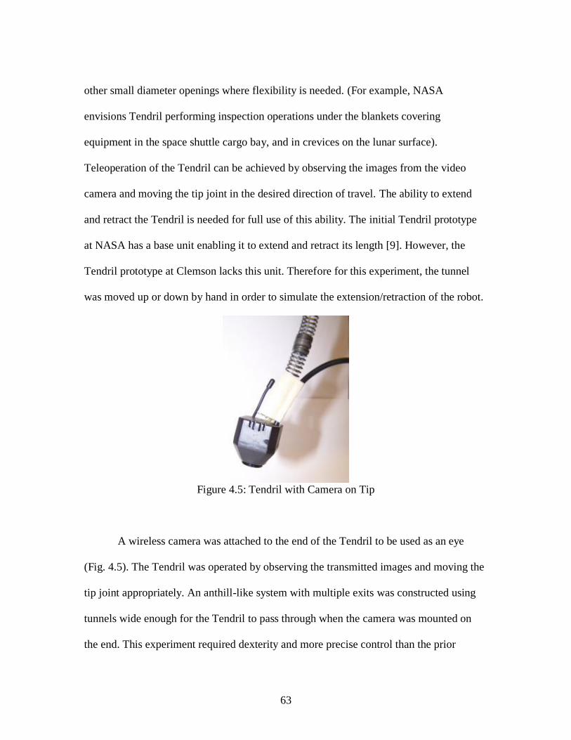
Figure 4.5: Tendril with Camera on Tip
A wireless camera was attached to the end of the Tendril to be used as an eye
(Fig. 4.5). The Tendril was operated by observing the transmitted images and moving the
tip joint appropriately. An anthill-like system with multiple exits was constructed using
tunnels wide enough for the Tendril to pass through when the camera was mounted on
the end. This experiment required dexterity and more precise control than the prior

64
biologically inspired experiments. The camera was mounted so that its position in
relation to the azimuth was known.
Figure 4.6: Environment for the Teleoperation of the Tendril
Next the Tendril and camera were placed in the tunnels in order to explore the
many exits available. An object was placed near one of the exits and the Tendril was used
to find the block in the tunnel (Fig 4.6). The tip joint alone was moved since it was used
to guide the Tendril via the camera. The goal of this experiment was to use the Tendril
like the eye stalk of a snail, so it needed to be able to move about freely and observe its
surroundings. A snail can bend its eyestalks and can extend and retract them as well. The
tip of the Tendril was inserted into the tunnel so that it could be turned from side to side
to observe its surroundings. Then a path was chosen and the tunnel was moved forwards.
This was repeated until the camera saw the obstacle in the tunnel. It was difficult to
perform this experiment since the camera available was larger than the one NASA uses

65
and the fuzzy picture and lack of light made it difficult to see where the Tendril was
headed.
If the Tendril is to be used in general tunnel environments, it will need a light
source so the camera can see. One issue that arose was that the camera‘s weight caused
the Tendril to sag. This could be resolved by using a smaller camera in future
experiments. Overall, this experiment was a success because the Tendril was able to
explore the tunnels even when encumbered by the weighty camera. If a camera is light
enough, then it could be placed on the tip of a Tendril-like continuum manipulator and
mounted on a robot to be used as an eyestalk to look around obstacles.
III. Obstacle Removal
The ability to remove obstacles from a robot‘s path would be of great benefit to
robots operating in remote areas. Rather than going around a small obstacle, a robot could
use a discrete flicking action to swat obstacle from its path. Another approach would be
to position the manipulator near the obstacle and slowly lever it out of the way. If the
robot were to get stuck, it could potentially dig itself out. The following experiment was
designed to test the ability of the Tendril to remove obstacles from its surroundings.

66
Figure 4.7: Swatting Ping Pong Ball
In the first part of this setup the Tendril was used to fling objects out of its way
similar to the motion of a komodo dragon‘s tail. A ping pong ball was placed upon the
end of a wrench and then the Tendril was swung in the appropriate direction. The ping

67
pong ball was launched off of the wrench like a golf ball off a tee (Fig. 4.7). Small light
objects are easy for the Tendril to manipulate, but heavier objects pose a problem. When
a heavier obstacle was placed in front of the Tendril, the Tendril‘s springs bent around
the object rather than moving it out of the way. This effect was observed before when
trying to lift object with the Tendril. The slack in the side lines caused by increasing the
Tendril‘s elevation causes the Tendril‘s tip to sag to either side when a load is placed on
the tip. This is an example of the wider disadvantage inherent in the design of compliant
continuum structures.

68
Figure 4.8: Removal of Balls from Tray

69
In the second setup, the Tendril was used like a wrecking ball to clear ping pong
balls off of a tray in a predetermined order (Fig. 4.8). A discrete motion is best for this
experiment since the only important variable is the azimuth. The tip was moved in the
azimuth direction of the desired ball to remove. A faster movement caused the ping pong
balls to fly further. They key point here is that the task was achieved with a very simple
but effective strategy, without the need for complex models or controllers. This suggests
that use of Tendril in impulsive manipulation tasks using simple motion strategies could
be highly effective.
IV. Grasping
The grasping and manipulation of an object is a fundamental part of robotics. In
order to interact with the world a robot needs to be able to manipulate its surroundings.
Experiments using Tendril for manipulation were conducted. In this setup the Tendril
grasped at a ring suspended in the air in order to remove it from its base and relocate it to
a different area (Fig. 4.9 and 4.10). Similar to carnival games of chance, it requires some
skill to move the Tendril accurately when trying to pick up the ring.
Figure 4.9: Tendril Lifting Ring and Placing on Base

70
Figure 4.10: Tendril Lifting Ring Off of Base
V. Discussion of Results
The experiments show that the Tendril has many potential uses that were not
envisioned previously. The stability experiment showed that the Tendril could be
operated simply to act in a manner similar to a biological tail to grip objects. The stability
of a robot with a continuum element can be increased by anchoring the continuum
element to a reliable point so that its other manipulators can have a stable base to move
from. Teleoperation of the Tendril using a small tip-mounted camera demonstrates its
potential effectiveness for inspection of narrow enclosed spaces that are a priori
unknown. However, teleoperation requires more precise and thus more complex control.

71
The operation and control strategy for the Tendril depends on what it needs to do.
Continuous control is useful for tasks that require precision. Discrete control is better for
moving in a general direction. If the Tendril is to be controlled discretely, by flicking it
towards obstacles, then the speed can be adjusted to increase the force of the swing. The
skill of the Tendril‘s operator is important when directly controlling the Tendril. Just like
casting a fishing line or controlling a puppet, it takes some amount of learning to do it
well.

72
CHAPTER FIVE
CONCLUSION
The research presented in this Thesis demonstrates that Tendril-type robots have
huge potential. There remains however much work to be done to improve the
performance of the current Tendril design.
The new geometric models developed in Chapter 2 should serve as the foundation
for improving the model-based performance of the Tendril in the future. However,
currently their effectiveness is limited, with much more that should be done to make sure
the models represent the true behavior of the system. The key problem is that numerous
unobservable and difficult-to-model effects in the hardware produce sufficient ―noise‖ to
significantly reduce the effectiveness of the models. There are numerous mechanical
improvements that can (and need to) be made in future hardware designs in order to
improve the behavior of the Tendril. The (de)compression problem can be fixed by
replacing the compression springs with tension springs, but they would be stiffer to
move. Slack in the line can be (at least partially) fixed by properly attaching the tendon
strings to the pulley or applying some sort of spring system to draw in the slack.
Balancing the motors and making sure that they are centered would drastically improve
performance. The effects of gravity and torsion on the springs should also be added to the
model. Future models should strive to take dynamic effects into consideration. Any load
that the Tendril would carry will require compensation since the tip of the Tendril will
otherwise sag to the side or downwards because of slack in the line and gravity. There are
also improvements that could be made to the basic control strategy. The top joints should

73
be moved more slowly than the bottom joints because as you travel from tip to top, each
joint is carrying an increasing weight. It would be safer to move the top joint slowly to
avoid ―cracking the whip,‖ unless that is the movement‘s intention.
The methods discussed in Chapter 3 reveal a new way of looking at continuum
robot operation. When a robot is used for a task, it seems advantageous to model its
motion on the behavior of an animal that perform a similar task. After all, the animal can
do it, so why not the robot? Natural continuum manipulators come in varying shapes and
sizes. Tongues, elephant trunks, tapir snouts, the tentacles on star-nosed moles, the arms
of cephalopods, and the eye stalks of snails are all continuum manipulators. Other
animals have hyper-redundant appendages, such as the tails of monkeys or the bodies of
snakes. All of these can work as models for a robot. Whether the manipulator is intended
for local body stability, grasping, or sensing, there are animals that do the same tasks.
Continuum structures can be simplified by using a discrete control strategy instead of
precise but more complex to control movements. The key inferences of Chapter 3 are that
the construction of a soft continuum robot should depend on the environment it will be
used in, and that an appropriate combination of continuum and discrete elements is likely
to significantly improve the performance of these robots.
The experiments in Chapter 4 apply some of the principles from Chapter 3 to the
operation of the Tendril and show that the Tendril has many uses that were not thought of
previously. A Tendril-like robot can potentially be used to increase the stability of an
overall system it is part of, like a tail on some animals. A reliable way to attach ad detach
the tip would be needed unless more joints were to be added to the Tendril. Teleoperation

74
of the Tendril reveals that it would make a useful tool to have when exploring confined
areas. The ability to look in nooks and crannies would be useful for exploration of
tunnels, pipes, or other similar structures. Many robots go around obstacles or avoid them
all together, and the alternative approach, moving the obstacles, has hardly ever been
considered. The current configuration of the Tendril does not allow for much load lifting
but it can move lightweight objects. If Tendril was used to explore a tunnel, a cave-in
might not be a disaster since it could move small rocks and squeeze through cracks
between others. The manipulation experiments suggest that, although it is not designed or
best suited for it, the Tendril could manipulate delicate objects.
The Tendril is a versatile robot and has the potential to do many things. The many
uses of monkey tails, octopus arms, and elephant trunks show how versatile a
conformable limb can be. Further research and experiments with the Tendril and Tendril-
like robots are likely to reveal other a priori unseen possibilities.

75
APPENDIX
Qmotor Control Code
The C code used in the basic Qmotor control program for the Tendril continuum
manipulator is given below.
// ========================================================================
// QMotor - A PC Based Real-Time Graphical Control Environment
// (c) 2000 QRTS
// ---------------------------------------------------------------
// Control Program : SimpleControl.cpp
// Description : The simple control example from the QMotor manual,
// "Getting started" section.
// Author : Matt Feemster, Markus Loffler
// Start Date : Tue Feb 22 10:30:57 est 2000
// ========================================================================
// ----- QRTS libraries -----
#include "ControlProgram.hpp"
#include "IOBoardClient.hpp"
// ----- C standard libraries -----
#include <math.h>
//===========================================================================
// Class definition of the SimpleControl class
//===========================================================================
class SimpleControl : public ControlProgram
{
protected:
double rate; // velocity
int algorithm; // choice of algorithm
int joint; // choice of joint
int az[2]; // azimuth
int el[2]; // elevation
int motor[4]; // motor values
double motorout[4]; // voltage sent to motor
int motready[4]; // ready flags
IOBoardClient *iobc; // IOBoardClient
public:
SimpleControl(int argc, char *argv[]) : ControlProgram (argc, argv){};

76
// Constructor. Usually no need to make changes here
~SimpleControl () {};
// Destructor. Usually no need to make changes here
// ----- User Functions -----
// This functions need to be implemented by the user in order to implement
// his control application. The user does not need to implement all of them,
// but usually at least enterControl(), startControl(), control() and
// exitControl() are implemented.
virtual int enterControl();
virtual int startControl();
virtual int control();
virtual int stopControl();
virtual int exitControl();
};
//===========================================================================
// SimpleControl::enterControl
// --------------------------------------------------------------------------
// This function is called when the control program is loaded. In standalone
// mode, this happens immediately. When using the GUI, it happens when the
// user loads the control program.
// Use this function to register control parameters, to register log variables
// and to initialize control parameters. After this function has completed,
// the base class ControlProgram will try to load a configuration file and
// eventually overwrite the initialized values.
// To indicate an error in enterControl() and to prevent the loading
// of the control, set the d_status data member to error and return -1
//===========================================================================
int SimpleControl::enterControl()
{
// ----- Register the log variables -----
registerLogVariable (&motor[0], "motor0", "motor0");
registerLogVariable (&motor[1], "motor1", "motor1");
registerLogVariable (&motor[2], "motor2", "motor2");
registerLogVariable (&motor[3], "motor3", "motor3");
// ----- Register the control parameters -----
registerControlParameter (&rate, "rate", "Rate of Movement");
registerControlParameter (&algorithm, "algorithm", "Algorithm");
registerControlParameter (&joint, "joint", "Joint");
registerControlParameter (&az[0], "az0", "Azimuth0");
registerControlParameter (&el[0], "el0", "Elevation0");
registerControlParameter (&az[1], "az1", "Azimuth1");
registerControlParameter (&el[1], "el1", "Elevation1");
registerControlParameter (&motor[0], "motor0", "Motor 0");
registerControlParameter (&motor[1], "motor1", "Motor 1");

77
registerControlParameter (&motor[2], "motor2", "Motor 2");
registerControlParameter (&motor[3], "motor3", "Motor 3");
// Set all control parameters initially to zero
clearAllControlParameters();
// Start message
d_messageStream
<< endl << "----- " << d_applicationName << " -----" << endl << endl;
return 0;
}
//===========================================================================
// SimpleControl::startControl
// --------------------------------------------------------------------------
// Called each time a control run is started. If running from the GUI, this
// will be called each time the START button is pushed. Do setup that must
// occur before each control run here (eg. initializing some counters,
// connections to needed servers). Log variables are initialized here.
// To indicate an error in enterControl() and to prevent control execution,
// set the d_status data member to error and return -1
//===========================================================================
int SimpleControl::startControl()
{
//clearAllLogVariables();
// ----- Initialize your clients here -----
const char *ioboardServerName =
d_config.getStringEntry("ioBoardServerName", "qrts/iobs0");
iobc = new IOBoardClient(ioboardServerName);
if (iobc->isStatusError())
{
d_status.setStatusError()
<< d_applicationName << ": [SimpleControl::startControl()] "
<< "Error connecting to IO board server " << ioboardServerName << endl;
delete iobc;
iobc = 0;
return -1;
}
// Initialize motor state
step = 0;
for(i=0; i < 4; i++)
motready[i] = 1;
return 0;
}

78
//===========================================================================
// SimpleControl::control
//----------------------------------------------------------------------------
// Called each control cycle. Do your input, control computations, and output
// here. If you return 0, the control will continue to execute. If you return
// nonzero, the control will abort. You may want to abort if some error
// condition occurs (excessive velocity, etc.)
//===========================================================================
int SimpleControl::control()
{
int enc[4]; //Current encoder values
//Read in the encoder values
enc[0] = iobc->getEncoderValue(0);
enc[1] = iobc->getEncoderValue(1);
enc[2] = iobc->getEncoderValue(2);
enc[3] = iobc->getEncoderValue(3);
double max_time; //Maximum time limit
//Set the rate of movement to a reasonable range
if(rate > 3.0) rate = 3.0;
if(rate < 0) rate = 0;
int enc_error = 100; //Maximum allowable encoder error
// set motor outputs
for(i=0;i<4;i++){
if(enc[i] < motor[i]) motorout[i] = rate; //If it is not in position yet, keep going
if(enc[i] > motor[i]) motorout[i] = -rate; //If it is has gone past then turn around
//If it is within error tolerances, stop the motor
if(enc[0] > motor[0]-enc_error && enc[0] < motor[0]+enc_error)
motready[0]=1; motorout[0] = 0.0;
iobc->setDacValue(i,motorout[i]); //Send the output voltage to D/A Channels
}
if(d_elapsedTime > max_time) return -1;
// IMPORTANT: Be aware of ouput limits of D/A channels for specific I/O board.
return 0;
}
//===========================================================================
// SimpleControl::stopControl()
//----------------------------------------------------------------------------
// Called each time a control run ends. If running from the GUI, this
// will be called each time the STOP button is pushed, or when a timed run
// ends, or when the control aborts itself.
// Use this function to zero out DACs and to disconnect from the servers
//===========================================================================

79
int SimpleControl::stopControl()
{
iobc->setDacValue(0,0.0);
iobc->setDacValue(1,0.0);
iobc->setDacValue(2,0.0);
iobc->setDacValue(3,0.0);
// Disconnect from IO board server
delete iobc;
return 0;
}
//===========================================================================
// SimpleControl::exitControl
// --------------------------------------------------------------------------
// This function is called when the control is unloaded. In standalone
// mode, this happens after one control run has completed. When using
// the GUI, it happens when the user loads a new control program or
// exits the GUI.
// This function could be used to cleanup allocated memory
//===========================================================================
int SimpleControl::exitControl()
{
return 0;
}
//===========================================================================
// main()
//----------------------------------------------------------------------------
// The main function instantiates the object and goes into the mainloop
//===========================================================================
main (int argc, char *argv[])
{
SimpleControl *cp = new SimpleControl(argc, argv);
cp->run();
delete cp;
}

80
REFERENCES
[1] C. Wright, A. Johnson, A. Peck, Z. McCord, A. Naaktgeboren, P. Gianfortoni, M.
Gonzalez-Rivero, R. Hatton, and H. Choset, ―Design of a modular snake robot,‖
Intelligent Robots and Systems, 2007. IROS 2007. IEEE/RSJ International
Conference on, pp. 2609-2614, Oct. 29 2007-Nov. 2 2007.
[2] 2008. [Online]. Available: http://www.snakerobots.com/
[3] J. Ostrowski and J. Burdick, ―The geometric mechanics of undulatory robotic
locomotion,‖ International Journal of Robotics Research, vol. 17, no. 7, pp. 683-
701, 1998.
[4] S. Hirose, Biologically Inspired Robots. Oxford University Press, 1993, pp. 147-
155.
[5] 2008. [Online]. Available:
http://www.cs.cmu.edu/~biorobotics/serpentine/serpentine.html
[6] M. W. Hannan and I. D. Walker, ―Analysis and experiments with an elephant‘s
trunk robot,‖ Advanced Robotics, vol. 15, pp. 847-858, 2001.
[7] W. McMahan, M. Pritts, V. Chitrakaran, D. Dienno, M. Grissom, B. Jones, M.
Csencsits, C.D. Rahn, D. Dawson, and I.D. Walker, ―Field Trials and Testing of
OCTARM Continuum Robots,‖ in IEEE International Conference on Robotics
and Automation, Orlando, FL, May 2006, pp. 2336-2341.
[8] L. Cowan, ―Azimuth, elevation, and coupling compensation for the Tendril.‖
Technical Report, Department of ECE, Clemson University, 2007.
<http://www.ces.clemson.edu/~ianw/Tendril.pdf>.
[9] J. Mehling, M. Diftler, M. Chu, and M. Valvo, ―A Minimally Invasive Tendril
Robot for In-Space Inspection,‖ in IEEE International Conference on Biomedical
Robotics and Biomechatronics, Pisa, Italy, 2006, pages 690-695.
[10] R. Cieslak and A. Morecki, ―Elephant trunk type elastic manipulator - a tool for
bulk and liquid materials transportation,‖ Robotica, vol. 17, pp. 11-16, 1999.
[11] H. Tsukagoshi, A. Kitagawa, and M. Segawa, ―Active hose: an artificial
elephant‘s nose with maneuverability for rescue operation,‖ in IEEE International
Conference on Robotics and Automation, Seoul and Korea, 2001, pp. 2454-2459.

81
[12] K. Suzumori, S. Iikura, and H. Tanaka, ―Development of flexible microactuator
and its application to robotic mechanisms,‖ in IEEE International Conference on
Robotics and Automation, 1991, pp. 1622-1627.
[13] Tufts University, ―Biomimetic Technologies Project Will Create First Soft-
Bodied Robots,‖ ScienceDaily. 30 January 2007,
<http://www.sciencedaily.com/releases/2007/01/070128105355.htm>.
[14] B. Trimmer, A. Takesian, and B. Sweet, ―Caterpillar locomotion: A new model
for soft-bodied climbing and burrowing robots,‖ in 7th International Symposium
on Technology and the Mine Problem, Monterey, CA, 2006.
[15] B. Jones and I. D. Walker, ―Practical kinematics for real-time implementation of
continuum robots,‖ in Proceedings of the 2006 IEEE International Conference on
Robotics and Automation (ICRA), Orlando, FL, 2006, pp. 1840-1847.
[16] I. A. Gravagne and I. D. Walker, ―Kinematic transformations for remotely
actuated planar continuum robots,‖ IEEE International Conference on Intelligent
Robots and Systems, San Francisco, CA, 2000, pp. 19-26.
[17] G. Robinson and J. B. C. Davies, ―Continuum robots—A state of the art,‖ in
Proc. IEEE Intl. Conf. Robotics and Automation, Detroit, MI, May 1999, pp.
2849–2854.
[18] L. Cowan and I.D. Walker, "―Soft‖ Continuum Robots: the Interaction of
Continuous and Discrete Elements," submitted to Artificial Life XI (ALIFE XI),
Winchester, UK, August 2008.
[19] R. Covey, ―Prehensile tail use during feeding and foraging of white-faced
capuchins, Cebus capucinus.‖ Department of Anthropology, Ohio State
University. 2005.
<https://kb.osu.edu/dspace/bitstream/1811/5877/1/RyanCovey.pdf>.
[20] F. Martin, and C. Niemitz, ―How do African elephants (Loxodonta africana)
optimise goal-directed trunk movements?‖ Jahresversammlung der Dt. Zool. Ges.
und der Dt. Ges. f. Parasitologie, Berlin, Germany, 2003, vol. 96, pp. 159- 2003.
[21] G. Sumbre, Y. Gutfreund, G. Fiorito, T. Flash, and B. Hochner, ―Control of
octopus arm extension by a peripheral motor program,‖ Science, September 2001,
vol. 293, pp. 1845-1848.
[22] 2007. [Online]. Available:
http://news.nationalgeographic.com/news/2006/12/061212-octopus-video.html

82
[23] R. Anderson, ―Smart Octopuses?,‖ The Festivus. 2006, Vol. 38, Issue 1, pp. 7-9.
[24] 2008. [Online]. Available: http://www.staubli.com/
[25] 2008. [Online]. Available: http://www.irobot.com/
[26] 2008. [Online]. Available: http://www.nasa.gov/mission_pages/mer/index.html
[27] A. Crespi and A. J. Ijspeert, ―Amphibot ii: An amphibious snake robot that crawls
and swims using a central pattern generator,‖ in 9th International Conference on
Climbing and Walking Robots (CLAWAR 2006), 2006, pp. 19-27.
[28] 2008. [Online]. Available: http://sciencetrack.blogspot.com/2007/07/twining-
motion-of-vines.html
[29] K. Catania, ―Olfaction: Underwater ‗sniffing‘ by semi-aquatic mammals,‖ Nature,
2006, vol. 444, pp. 1024-1025.
[30] 2008. [Online]. Available:
http://www.tonmo.com/forums/showthread.php?t=11319
[31] J.L. Leeuwen, and W.M. Kier, ―Functional Design of Tentacles in Squid: Linking
Sarcomere Ultrastructure to Gross Morphological Dynamics,‖ Philosophical
Transactions of the Royal Society of London, 1997, vol. 352, pp. 551-571.
[32] 2008. [Online]. Available: http://imdb.com/title/tt0082971/
[33] 2008. [Online]. Available: http://www.ocrobotics.com/
[34] G. Immega and K. Antonelli, ―The KSI tentacle manipulator,‖ in IEEE
International Conference on Robotics and Automation, 1995, pp. 3149-3154.
[35] M. B. Pritts and C. D. Rahn, ―Design of an artificial muscle continuum robot,‖ in
Proceedings - IEEE International Conference on Robotics and Automation, 2004,
pp. 4742-4746.
[36] J. F. Wilson, D. Li, Z. Chen, and R. T. George, ―Flexible robot manipulators and
grippers: Relatives of elephant trunks and squid tentacles,‖ Robots and Biological
Systems: Toward a New Bionics?, 1993, pp. 474-479.
[37] N. Simaan, R. Taylor, and P. Flint, ―A dexterous system for laryngeal surgery,‖ in
IEEE International Conference on Robotics and Automation, New Orleans, LA,
2004, pp. 351-357.

83
[38] 2008. [Online]. Available: http://ad-blood.blogspot.com/2007/05/sanyo-xacti-
octopushand.html
[39] E. Haeckel, Kunstformen der Natur, 1904.
[40] A. Biewener, Animal Locomotion. Oxford University Press, New York, NY,
2003.
[41] Armour and J. Vincent, ―Rolling in Nature and Robotics: A Review,‖ in Journal
of Bionic Engineering Volume 3 Issue 4, Dec. 2006, pp. 195-208.