analysis of alternative uk heat decarbonisation pathways
TRANSCRIPT

Analysis of Alternative UK Heat Decarbonisation Pathways
For the Committee on Climate Change
August 2018

Page 2 of 159
Project Team Imperial College: Goran Strbac, Danny Pudjianto, Robert Sansom, Predrag Djapic, Hossein Ameli, Nilay Shah, Nigel Brandon, Adam Hawkes Cardiff University: Meysam Qadrdan
Acknowledgements
The authors are thankful to Ian Walker from Element Energy for providing comments related to cost data used in the modelling. Furthermore, the authors would like to express their gratitude to the Engineering and Physical Sciences Research Council for the support obtained through the Whole Systems Energy Modelling Consortium and Energy Storage for Low Carbon Grids programme, that supported fundamental research that led to the development of Integrated Whole-Energy System modelling framework that was applied in this study.

Page 3 of 159
Contents
Abbreviations 6
Extended Executive Summary .............................................................................................. 7 Context and objective of the studies ................................................................................ 7
Scope of the studies ......................................................................................................... 8
Overview of the investigated heat decarbonisation strategies .......................................... 9
Cost performance of core decarbonisation pathways ..................................................... 10
Impact of heat decarbonisation strategies on the electricity generation portfolio........... 16
Impact of uncertainties on the cost of decarbonisation .................................................. 20
Alternative heat decarbonisation strategies: district heating and micro-CHP .................. 23
Alternative heat decarbonisation strategies: regional scenarios ..................................... 24
The importance of cross-energy system flexibility and firm low-carbon generation ........ 26
Impact of future development of gas-based hydrogen production technologies ............. 32
Impact of improved energy efficiency and climate change .............................................. 34
The ability of the existing gas distribution system to transport hydrogen ........................ 36
Key findings .................................................................................................................... 37
Recommendations ......................................................................................................... 41
Further analysis 41
Decarbonisation of electricity supply and enhancement of system flexibility 42
Policy development for heat decarbonisation 42
Market design for flexibility 43
Pilot trials 43
Carbon emission targets for energy 44
Hydrogen production demonstration plants 44
Chapter 1. Introduction ................................................................................................. 45 1.1 Context ................................................................................................................ 45
1.2 Key objectives ...................................................................................................... 46
1.3 Scope of studies ................................................................................................... 47
1.4 Modelling approach ............................................................................................. 50
1.5 Key assumptions .................................................................................................. 52
Chapter 2. Analysis of alternative heat decarbonization pathways ............................... 58 2.1 Hydrogen pathways ............................................................................................. 59
2.1.1 Impact of future developments in gas-based hydrogen production technologies 65
2.1.2 Distributed versus centralised hydrogen production 67
2.1.3 Hydrogen-based district heating 69
2.1.4 The ability of the existing gas distribution system to transport hydrogen 70
2.1.5 Hydrogen storage 72

Page 4 of 159
2.2 Electric pathways ................................................................................................. 74
2.2.1 Electric-based district heating 76 2.3 Hybrid pathways .................................................................................................. 78
2.3.1 Impact of micro-CHP 81 2.4 Cost performance of core decarbonisation pathways ........................................... 83
2.5 Impact of heat decarbonisation strategies on the electricity generation portfolio 87
2.6 Alternative heat decarbonisation strategies ......................................................... 91
2.6.1 District heating and micro-CHP 91
2.6.2 Regional scenarios 92
Chapter 3. Sensitivity studies on the decarbonization pathways................................... 95 3.1 Key sensitivity factors........................................................................................... 95
3.2 Hydrogen Scenario ............................................................................................... 96
3.3 Electricity Scenario ............................................................................................... 99
3.4 Hybrid Scenario .................................................................................................. 101
3.5 Cross-cutting analysis across alternatives decarbonisation pathways ................. 103
3.5.1 Sensitivity across different decarbonisation options 103
3.5.2 Cost of decarbonisation across different scenarios 106 3.6 Impact of improved energy efficiency and changes in heat demand ................... 108
Chapter 4. The importance of energy system flexibility and alternatives to firm low-carbon generation ...................................................................................... 111
4.1 Alternatives to nuclear generation ..................................................................... 111
4.2 The interaction between thermal and electricity storage ................................... 115
4.3 Impact of long-term Thermal Energy Storage ..................................................... 118
Chapter 5. Conclusions and policy recommendations ................................................. 120 5.1 Conclusions ........................................................................................................ 120
5.2 Policy implications and recommendations ......................................................... 124
5.2.1 Further analysis 124
5.2.2 Decarbonisation of electricity supply and enhancement of system flexibility 125
5.2.3 Policy development for heat decarbonisation 125
5.2.4 New market design for flexibility 126
5.2.5 Pilot trials 126
5.2.6 Carbon emission targets for energy 126
5.2.7 Hydrogen production demonstration plants 127
Appendix A. Costs of alternative decarbonisation pathways ......................................... 128
Appendix B. Household conversion and heating appliance cost..................................... 135
Appendix C. Heat demand sensitivities .......................................................................... 138
Appendix D. Feasibility of transporting hydrogen using existing gas distribution system140 D.1 Objective ........................................................................................................... 140

Page 5 of 159
D.2 Methodology ..................................................................................................... 141
D.1.1 Gas network modelling 141 D.3 Case studies ....................................................................................................... 142
D.4 Key results ......................................................................................................... 142
D.4.1 Impacts of hydrogen transport on low-pressure networks 142
D.4.2 Impacts of hydrogen transport on medium pressure networks 143
D.4.3 Impacts of hydrogen transport on high-pressure networks 144
D.4.4 Estimation of hydrogen storage capacity needed across GB gas distribution networks 146
Appendix E. Gas network data ....................................................................................... 149
Appendix F. GB system model ....................................................................................... 158

Page 6 of 159
Abbreviations
ATR Auto Thermal Reformer
BECCS Bioenergy plant with Carbon Capture and Storage
BEIS Department for Business, Energy & Industrial Strategy
CCGT Combined Cycle Gas Turbine
CCS Carbon Capture and Storage
CHP Combined Heat and Power
DH District heating
EE Element Energy
H2 Hydrogen
HHP Hybrid Heat Pump
HP Heat pump
IWES Integrated whole energy system model
LDZ Local Distribution Zones
NG Natural gas
NIC Network Innovation Competition
OCGT Open Cycle Gas Turbine
P2G Power to Gas
PEM Proton Exchange Membrane
PV Photovoltaics
RES Renewable Energy Sources
RH Resistive heating
SGI Sustainable Gas Institute
SMR Steam Methane Reformer
SOE Solid Oxide Electrolyser
LT-TES Long-term Thermal Energy Storage

Page 7 of 159
Extended Executive Summary
Context and objective of the studies
Addressing the challenges related to decarbonisation of gas and heat, the Committee on
Climate Change (CCC) has identified multiple decarbonisation pathways for low-carbon
heating as proposed in the CCC’s October 2016 report, “Next Steps for UK Heat Policy”1.
Three central pathways have been identified: i.e. (i) by ‘greening’ the gas supply by
shifting to low-carbon hydrogen (H2), (ii) electrification of heat supported by low-carbon
power generation, or (iii) by potential hybrid solutions, with the bulk of heat demand,
met by electricity, and peak demands met by green gas2. Each pathway brings significant
challenges, and it was unclear whether there is a dominant solution and what the
implications are on the future infrastructure requirements and operational coordination
across energy systems in the UK.
In this context, the Integrated Whole-Energy System (IWES) model developed by
Imperial College London, has been applied to assess the technical and cost performance
of alternative decarbonisation scenarios for low-carbon heating in 2050 with the aim to:
- Understand the implications of alternative heat decarbonisation pathways on
electricity and gas infrastructures in the UK energy system in 2050 by:
o Analysing the interactions between the electricity and heat systems (including
various forms of storage)
o Optimising the interactions across different energy vectors to maximise the whole-
system benefits;
- Understand the economic performance and drivers of various pathways by:
o Comparing the whole system costs of alternative heat decarbonisation scenarios
in 2050, and beyond towards a zero-emissions energy system. For example,
comparing the costs of retaining gas distribution networks that are re-purposed
for hydrogen transport, against reinforcing the electricity grid under various low-
carbon heating scenarios
o Analysing the impact of uncertainties in technologies and costs;
- Provide fundamental evidence to support the development of policies for
decarbonisation of heating and the electricity system.
Comprehensive studies have been carried out to quantify the investment and
operational requirements as well as the costs of alternative heat decarbonisation
pathways for a representative energy system for Great Britain in 2050. These studies
1 Available at: https://www.theccc.org.uk/wp-content/uploads/2016/10/Next-steps-for-UK-heat-policy-Committee-on-Climate-Change-October-2016.pdf
2 A bioenergy focused pathway was not considered a core option, as the CCC’s 2011 Bioenergy Review suggested a limit of around 135 TWh of primary bioenergy that could be available to the UK power and gas systems.
Page 8 of 159
were carried out in the context of related activities in this area, including research
carried out by the Department for Business, Energy & Industrial Strategy (BEIS) research
on Heat and Strategic Options, research into the costs of future heat infrastructure for
the National Infrastructure Commission3, Network Innovation Competition (NIC) trials
etc.
The interactions across different energy vectors, i.e. electricity, gas, and heat systems
including different types of energy storage (electricity, hydrogen, thermal) have been
optimised using the IWES model to maximise whole-system benefits. In summary, the
IWES model minimises the total cost of long-term infrastructure investment and short-
term operating cost while considering the flexibility provided by different technologies
and advanced demand control, and meeting carbon targets. The IWES model includes
electricity, gas, hydrogen and heat systems, simultaneously considering both short-term
operation and long-term investment decisions4 covering both local district and
national/international level energy infrastructure, including carbon emissions and
security constraints.
Scope of the studies
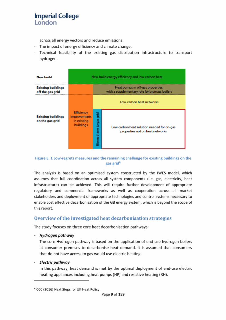
The CCC’s approach to low-carbon heat is presented in Figure E. 1. The scope of this
particular study includes quantification of the system costs of different heat
decarbonisation pathways, consistent with the CCC’s approach to low-carbon heat. The
CCC’s previous analysis has identified that converting all off-gas grid homes and some
direct electric heating to heat pumps, representing 18% of households5, and 13% of
households in urban areas to district heating is cost-effective. This modelling, therefore,
considers the costs of converting the remaining 71% of households to a low-carbon
heating technology.
The studies focus on:
- The cost performance of each decarbonisation pathway and cross-cutting analysis
across pathways;
- The interaction and optimal capacity portfolios of power system infrastructure
(generation, electricity network, electricity storage), hydrogen infrastructure
(production capacity, hydrogen network, storage), carbon capture and storage
infrastructure and heating infrastructure;
- The impact of uncertainties in key modelling assumptions and input parameters;
- The role and benefits of enabling technologies that can improve system flexibility
3 Element Energy and E4tech,” Cost analysis of future heat infrastructure,” a report for National Infrastructure Commission, March 2018.
4 This study focuses on the optimal investment needed to meet the 2050 system requirements and carbon target. The transition from the present to the optimised 2050 system warrants further studies.
5 Assuming 34.3m households by 2050
Page 9 of 159
across all energy vectors and reduce emissions;
- The impact of energy efficiency and climate change;
- Technical feasibility of the existing gas distribution infrastructure to transport
hydrogen.
Figure E. 1 Low-regrets measures and the remaining challenge for existing buildings on the gas grid6
The analysis is based on an optimised system constructed by the IWES model, which
assumes that full coordination across all system components (i.e. gas, electricity, heat
infrastructure) can be achieved. This will require further development of appropriate
regulatory and commercial frameworks as well as cooperation across all market
stakeholders and deployment of appropriate technologies and control systems necessary to
enable cost effective decarbonisation of the GB energy system, which is beyond the scope of
this report.
Overview of the investigated heat decarbonisation strategies
The study focuses on three core heat decarbonisation pathways:
- Hydrogen pathway
The core Hydrogen pathway is based on the application of end-use hydrogen boilers
at consumer premises to decarbonise heat demand. It is assumed that consumers
that do not have access to gas would use electric heating.
- Electric pathway
In this pathway, heat demand is met by the optimal deployment of end-use electric
heating appliances including heat pumps (HP) and resistive heating (RH).
6 CCC (2016) Next Steps for UK Heat Policy
Page 10 of 159
- Hybrid pathway
This pathway is based on the application of combining the use of gas and electric
heating systems, i.e. hybrid heat pump (HHP). The gas heating system in the Hybrid
system uses natural gas or carbon-neutral gas such as biogas or hydrogen to reduce
emissions from gas.
The study uses two main annual carbon emissions targets, i.e. 30Mt and 0Mt to identify
the implications of going to zero carbon; 10Mt is used in some studies to investigate the
system changes in the transition from 30Mt to 0Mt. Sensitivities of the results against
different assumptions (e.g. financing cost, heat demand, system flexibility, hydrogen
import, unavailability of nuclear) have also been studied and analysed.
A range of alternative strategies has also been investigated, with the core heat
decarbonisation pathways. This includes the implementation of:
- Regional decarbonisation strategies
The strategies combine one decarbonisation pathway with a different pathway with the
aim to find lower cost solutions:
o Use of hydrogen in the North of GB7 while the rest of the system is decarbonised
through HHP, in order to minimise investment in hydrogen networks.
o Use of hydrogen in urban areas while rural areas are decarbonised through HHP.
o Use of industrial HP-based district heating in urban areas.
- District heating
This consists of two scenarios including:
o National deployment of industrial-scale hydrogen boilers in district heating
networks (H2+DH);
o National deployment of industrial HP in district heating networks (Elec+DH);
- Micro-CHP
In this scenario, 10GW of micro-CHP is deployed in the Hybrid system that can displace
end-use HHPs and power generation.
The key results of the studies are described as follows.
Cost performance of core decarbonisation pathways
The annual system costs of different decarbonisation pathways were considered in this
study across three different annual carbon emissions targets, i.e. 30 Mt, 10 Mt, and 0
Mt8 are presented in Figure E. 2.
7 Scotland, North of England and North of Wales 8 H2[30], H2[10], and H2[0] refer to the H2 pathway with 30Mt, 10Mt, and 0Mt target respectively.
The same notation is used to identify the decarbonisation pathways (H2, Elec, Hybrid) and the carbon targets ([30],[10],[0]).

Page 11 of 159
Key assumptions
- Auto Thermal Reformer (ATR) combined with Carbon Capture and Storage (CCS) is
considered as the default technology for producing hydrogen from natural gas9;
otherwise, hydrogen is produced using electrolysis.
- Hydrogen is produced from gas in a centralised manner, in the regions which have
access to gas and carbon storage terminals, to maximise the benefits of economies
of scale and eliminate the need for national CCS infrastructure.
- 21 TWh of biogas and 135 TWh of primary bioenergy are used in all pathways.
- The assumed maximum capacity of low-carbon generation that can be deployed by
2050 for wind, PV, CCS, and nuclear is 120 GW, 150 GW, 45 GW, and 45 GW
respectively.
- 50% of the potential flexible technologies across electricity, heat and transport
sectors is assumed to be available to provide various system services. These include
controllable industrial and commercial loads, electric vehicles, smart domestic
appliances and preheating.
- Optimised energy storage including electricity, thermal, and hydrogen storage
- Household level energy efficiency measures (including insulation) are assumed to
be deployed consistent with the CCC’s scenarios for 2050. There are no costs
associated with energy efficiency in the modelling.
- Light vehicle transport is assumed to be electrified in all scenarios, leading to 111
TWh of electricity demand by 2050.
- 135 TWh of industrial space heating demand is assumed to be either electrified or
hydrogenated in the respective pathways.
Figure E. 2 Annual system cost of core decarbonisation pathways
9 Assumed natural gas price: 67p/therm

Page 12 of 159
The IWES model optimises 29 system cost components10 which are grouped into five
capex (C) and two opex (O) categories as follows:
a. C: Electricity generation – annuitised capital cost of electricity generation that
encompasses both low-carbon and non-low carbon generation.
b. C: Electricity networks – annuitised capital cost of the electricity network that
consists of the cost of the distribution network, transmission network and
interconnectors.
c. O: Electricity – annual operating cost of electricity that includes all the variable
operating costs (e.g. fuel, O&M) as well as start-up, and fixed operating costs.
Carbon prices are excluded from this analysis.
d. C: Electric heating +storage – annuitised capital cost of electric heating and
energy storage in electric scenario includes the capital cost of the heat pump
(domestic and industrial), resistive heating, electric storage, thermal energy
storage, cost of end-use conversion (replacing gas-based heating to electric),
cost of appliances and cost of decommissioning gas distribution due to
electrification.
e. C: H2+CCS+P2G – annuitised capital cost of hydrogen and CCS infrastructure,
including the cost of all hydrogen production technologies, cost of hydrogen and
CCS networks, cost of hydrogen storage and carbon storage.
f. O: NG+H2+CCS – annual operating cost of the natural gas system that includes
fuel cost of gas-based hydrogen production technologies, e.g. SMR and ATR, cost
of hydrogen import, operating cost of hydrogen storage and the fuel cost of the
natural gas (NG)-based boiler.
g. C: Non-electric heating – annuitised capital cost of non-electric heating includes
the capital cost of natural gas (NG) and hydrogen-based boilers, cost of district
heating infrastructure, conversion cost and the cost of maintaining the existing
gas distribution network.
The key findings are summarised as follows:
1. Costs of alternative decarbonisation pathways are relatively similar for 30Mt, but
the cost differences increase for the H2 pathway in 0 Mt case
As shown in Table E. 1, the system costs of the decarbonisation pathways at the carbon
emissions target of 30Mt/year are broadly similar; the cost difference between core
pathways, i.e. Hybrid, Electric and H2 is within 10%, and hence the ranking may change
when different assumptions apply. The costs marginally increase at 0Mt/year, except in
H2 pathways as the hydrogen production shifts from gas to electricity, which
significantly increases the cost of hydrogen infrastructure (due to the shift from ATR to
electrolysers).
10 More description of the cost components used in the IWES model can be found in Appendix A.

Page 13 of 159
Table E. 1 Cost performance of different decarbonisation pathways
Pathways Cost (£bn/year)
30Mt 10Mt 0Mt
Hybrid 81.6 84.8 88.0
Elec 87.8 89.5 92.2
H2 89.6 90.2 121.7
In the H2 pathways, the cost of hydrogen infrastructure is dominated by the cost of gas
reforming plants and hydrogen storage, which is optimised in the study. The function of
hydrogen storage11 is to improve the utilisation of the hydrogen infrastructure by
reducing the capacity of hydrogen production plants. For example, the peak demand of
hydrogen in the H2 30Mt case reaches 260 GW while the total capacity of hydrogen
production proposed by the model is only 103 GW (costs £8bn/year). In order to meet
such demand, there is a need for around 20 TWh of hydrogen storage (costing £6.4
bn/year). Without storage, the hydrogen production capacity would be 2.6 times larger
which would increase the cost of the H2 pathway by £13 bn/year).
2. The Hybrid pathway is the least-cost under central assumptions while the cost of
the H2 pathway is found to be the highest cost, compared to the other pathways.
The cost of each of the core pathways is presented in merit order in Table E. 1. The
Hybrid scenario is identified as the most cost-effective decarbonisation pathway, with
the hydrogen pathway being the most expensive. All of these cost results involve a
broad range of uncertainty (see page 20).
There are several key drivers contributing to the cost performance of different
decarbonisation pathways:
- The Hybrid pathway is based on high-efficiency HHPs that supply the baseload of heat
demand while providing the flexibility to use gas during peak demand12 conditions or
low renewable output. This flexibility reduces the capacity requirement of the power
system infrastructure required to meet peak demand compared to the capacity
required in the Electric pathway. This also reduces the capacity required for security
of supply reasons and the corresponding costs. It is important to highlight that the
model determines the level of capacity needed to maintain the same level of security
in all pathways.
- In general, the Electric pathway requires the highest investment in electricity
11 Combination of underground storage, e.g. salt caverns as is currently used in Teesside and medium pressure over ground storage
12 In order to test the adequacy of the system capacity to deal with the extreme weather conditions, 1-in-20 years events are considered, i.e. extreme cold winter week coinciding with low output of renewables.

Page 14 of 159
networks, particularly at the distribution level, due to a significant increase in peak
demand driven by heat electrification. Network costs in the Hybrid pathway are
significantly lower than in the Electric pathway as the use of the gas boiler
component of a hybrid heat pump during peak demand can efficiently reduce the
need for distribution network reinforcement (although some network reinforcement
is required to accommodate renewable generation). The H2 pathway tends to require
significantly lower electricity distribution network reinforcements, when compared to
the other pathways, except in the 0Mt case where significant reinforcement is
needed to accommodate demand-side flexibility and integrate more renewable
generation to achieve the carbon target cost-effectively (as it is assumed that all
hydrogen is produced domestically via electrolysis in the 0Mt case, requiring
additional low-carbon electricity generation).
- In the H2 pathway, natural gas is decarbonised through hydrogen production via gas
reforming with CCS13. This reduces the need for investment in low-carbon electricity
generation but requires higher investment in the hydrogen and CCS infrastructure
compared to other pathways14. However, the overall operation and investment cost
associated with the hydrogen system in H2 pathway exceeds the benefits associated
with lower investment in electricity generation. The cost difference becomes much
more pronounced in 0Mt case as the cost of hydrogen infrastructure increases
substantially (as shown in Figure E. 2) due to the shift from ATR to electrolysers
(capex of electrolysers is higher than the capex of ATR), although the increase in
capex can be partially offset by the reduction in the gas opex.
- The H2 pathway is characterised by the lowest energy efficiency due to a number of
energy conversion processes involved: heat pumps are operated between 200% and
300% efficiency (or higher)15, whereas converting gas to hydrogen for use in domestic
gas boilers is 80% efficient or less (depending on the efficiency of hydrogen boilers
and efficiency of the hydrogen production). However, the cost of hydrogen boilers is
significantly lower than HP or HHP.
- There is a need to replace gas appliances in both the H2 and Electric pathways, which
increases the costs of corresponding scenarios. Hydrogen boilers are significantly
lower cost than heat pumps16, at £75/kWth for a boiler and £600/kWth for a heat
13 Assuming Auto-thermal Reforming, with 88% HHV efficiency and 96% capture rate, based on Element Energy (2018) Hydrogen Infrastructure: Summary of Technical Evidence
14 The CCC specified that 135 TWh of primary bioenergy should be used to provide ‘negative emissions’ via Bioenergy plant with Carbon Capture and Storage (BECCS), though these negative emissions are not considered within the carbon constraint in the model as these are accounted for across the economy. The model chose to use BECCS to produce hydrogen in all cases, with the hydrogen being used in either hydrogen-based power plant or gas boilers. The cost of BECCS plant is included in all pathways. Efficiencies for BECCS plant were assumed to be 69% for gasification and 40.6% for electricity generation.
15 Annual average COP of HP used in the study is 2.7. 16 More detailed information about household conversion costs can be found in Appendix B.

Page 15 of 159
pump but have higher operating costs. In the Hybrid pathway, on the other hand,
there is no need to replace other gas appliances, which minimises the household
conversion cost.
3. Electric and Hybrid pathways have greater potential to reduce emissions to close
to zero at a reasonable cost, compared to the H2 pathway.
Comparing the system costs of 30Mt, 10Mt and 0Mt cases in Table E. 1, the results
demonstrate the following:
- While the cost to meet a 10Mt carbon target in the H2 pathway increases only by
£0.6bn/year compared to the cost in 30Mt scenario, there is a significant increase in
cost (more than £30bn/year) in H2 pathways when carbon target changes from 30Mt
to 0Mt, driven by the change in hydrogen production from ATR to electrolysers. The
system costs of electrolysers are higher than ATR as the application of electrolysers
also requires a significant increase in investment in the low-carbon electricity
generation. Improved carbon capture rates on gas reforming plant or importing low-
carbon hydrogen to the UK could allow for reduced emissions in the H2 pathway.
- The costs of the Electric and Hybrid pathways in the 0Mt cases are also 4 - 6 £bn/year
higher than the corresponding costs in 30Mt; this is driven by the increase in
electricity generation capex as a higher capacity of nuclear is needed to provide a
firm low-carbon electricity source. The increased nuclear capacity is also observed in
H2 0Mt case. The implication is that fewer emissions are available to the reserve and
response plants that are required to back up variable renewables in these pathways,
requiring firm low-carbon generation.
- Achieving zero emissions with a hybrid pathway will depend on the availability of low-
carbon biogas, as well as consumer usage of the hybrid heat pump.
The analysis demonstrates that:
- Systems with more stringent carbon emission targets will lead to higher costs;
- Further decarbonisation beyond 30 Mt is possible at limited additional costs (few
billions per year) in the hybrid and Electric pathways; this is also true for deep
decarbonisation towards a zero-emissions energy system.
- Electric and Hybrid pathways provide more optionality towards a zero-carbon future
compared to the H2 pathway, which is limited up to 10 Mt unless there is an
improvement in the capture rate of CCS.
4. The costs of low-carbon systems are dominated by capital expenditure (capex)
while operating expenditure (Opex) is significantly lower.
In the 30Mt cases, the ratio between the system opex and total cost is relatively small,
i.e. less than 25% in the H2 pathway, 5% in Electric, and 6% in Hybrid. Towards zero
carbon, the opex component in all decarbonisation pathways reduces significantly as

Page 16 of 159
most of the energy is produced by zero marginal cost renewable resources and low
operating cost nuclear generation, while the use of gas is limited to only low-carbon gas
(biogas, bioenergy), with any hydrogen being produced by electrolysis supplied by low-
carbon electricity generation. This implies that the system costs will be very sensitive to
capital and financing cost of infrastructure17 and much less sensitive to fluctuations in
future gas prices.
Impact of heat decarbonisation strategies on the electricity
generation portfolio
Different decarbonisation pathways require substantially different electricity generation
portfolios, as the choice of heating pathway will have significant implications for gas and
electricity systems. Optimal generation portfolios for the core decarbonisation scenarios
are presented in Figure E. 3. Coordination of the design and operation of gas, heat and
electricity systems is important for minimising the whole-system costs of
decarbonisation.
Figure E. 3 Optimal generation portfolio in the core decarbonisation pathways
From the optimal generation portfolio proposed by the model, a number of conclusions
can be derived:
1. Maximum capacity of low-carbon generation that is assumed to be available by
17 Hurdle rates used in the study are between 3.5% and 11% depending on the technologies.

Page 17 of 159
2050 is sufficient to reach the zero-carbon target18.
Across all scenarios a significant capacity of low carbon electricity generation PV, wind
and nuclear is required, representing an increase of 130-450% of electricity generation
capacity on today’s levels (of around 100 GW). The optimal generation portfolio also
includes hydrogen based CCGT and OCGT plant. There is only one case, i.e. 0Mt H2
pathway, where the capacity of PV, wind and nuclear hit the upper limits of UK
deployment potential by 205019. This increase in electricity generation capacity implies
significant build rates over the period to 2050, in order to meet the decarbonisation
targets. Any constraints on build rates, such as financing, materials or skills issues could
reduce the achievable level of energy system decarbonisation by 2050.
2. Energy system flexibility and interactions across different energy systems
significantly influence the power generation portfolio.
The optimal portfolio of PV, wind, nuclear and hydrogen-based CCGT/OCGT is based not
only on the levelized cost of electricity (LCOE) of these generation technologies, but also
system integration costs of all technologies are considered. The whole-system cost
would depend on the level of flexibility which can be provided by the interaction
between the heat and electricity sectors, which will impact deployment rates of low
carbon generation technologies, aimed at meeting the carbon target at minimum costs.
It is important to note that cross-vector flexibility and the link between local and
national levels services across different time-scales are considered by IWES model in all
scenarios and that this cross-vector coordination minimises cost of decarbonisation of
the whole-energy system; in the absence of cross-vector coordination the overall system
costs would significantly increase.
The modelling results demonstrate that providing additional system flexibility (beyond
cross-sector flexibility) can further reduce the annual system cost by up to £16 bn/year.
The flexibility provided by demand-side management or energy storage across different
energy vectors (electricity, gas, heat) can improve the utilisation of low-carbon
generation and reduce the overall requirement of production capacity and network
infrastructure reinforcement. For example, if heat demand is supplied by electric
heating, reducing the peak of heat demand by preheating20 or using thermal storage can
18 The CCC defined the upper UK deployment limit for low-carbon electricity generation technologies as wind, PV, CCS and nuclear is 120 GW, 150 GW, 45 GW and 45 GW for wind, PV, CCS and nuclear respectively.
19 Due to insufficient capacity of low-carbon electricity generation, this case cannot meet the zero-carbon target and the annual carbon emissions were 2 Mt/year.
20 Preheating involves heating the households earlier than it would be otherwise done while utilising inherent heat storage in the fabric of the houses. This type of flexibility is critical for reducing system peaks, enhancing the value of the provision of balancing services and increasing utilisation of renewables by electric heating, which significantly reduces the cost of decarbonisation.

Page 18 of 159
reduce the required firm generation capacity21. The studies demonstrate that most of
the value of system flexibility (including preheating) contributes to the savings in the
capex of low-carbon electricity generation which is a dominant cost component (Figure
E. 1).
3. A significant capacity of firm low-carbon generation is needed in all pathways with
a 0Mt carbon target
Analysis demonstrated that meeting a zero-emission target cost effectively would
require a significant capacity of nuclear generation in all pathways, due to the variability
of renewable production and the need to eliminate emissions associated with
management of demand-supply balance. Hence, in the 0 Mt case, a significant amount
of capacity of variable renewables is replaced by firm low-carbon generation capacity,
i.e. nuclear. The results demonstrate that although in the short and medium term the
focus can be on deployment of variable RES, in the long-term, to achieve a zero-carbon
emissions target, firm low-carbon generation technologies such as nuclear (or
alternatives) will be required, e.g. for the 0Mt, in all core pathways, more than 40 GW of
nuclear generation is deployed. The appropriate portfolio of power sector technologies,
therefore, depends on the desired level of decarbonisation of the energy system.
4. Pre-combustion CCS generating plant is more attractive than the post-combustion
CCS.
No post-combustion CCS plant is selected due to the high cost of the technology and the
presence of residual carbon emissions (it is important to note that post-combustion
fossil CCS cannot be used in 0Mt scenario due to residual carbon emissions). There is,
however, a significant volume of pre-combustion CCS, i.e. hydrogen-based combined
cycle gas turbine and hydrogen-based open cycle gas turbine primarily in the Electric and
Hybrid scenarios. Pre-combustion-hydrogen-based generation can be considered as
complementary to CCS generation as it enables decarbonisation of traditional gas plant
technologies and can provide flexibility while making efficient use of the hydrogen
infrastructure.
5. The total capacity of electricity generation in the Electric pathways is significantly
larger than in other pathways.
Full electrification of heating demand in the Electric pathway will substantially increase
peak electricity demand. Hence the corresponding amount of firm-generation capacity
in the Electric pathway is about 100 GW larger compared to other pathways. It should be
noted that in the Electric pathway there is a significant amount of peaking plant (OCGTs)
that are supplied by biogas and operate at very low load factors (operating during high
peak demand conditions driven by extremely low external temperatures). In the Hybrid
21 In the Electric 0 Mt scenario, the use of preheating can reduce more than 40 GW of firm generating capacity.

Page 19 of 159
pathway, on the other hand, the extreme peak of heat demand is directly supplied by
gas boilers using biogas in the gas grid rather than electricity, and hence the capacity
requirement for peaking plant is much lower.
Considering the uncertainty across different heat decarbonisation pathways and
emissions targets, “low/no regrets”22 capacity of specific low-carbon generation
technologies can be determined by taking the minimum of the proposed capacity for the
corresponding generation technology across different pathways (given the costs of
different low carbon generation technologies) and across emissions targets. This
suggests that a capacity of at least 74 GW of wind generation is useful in all scenarios,
given the seasonal profile of both wind generation and energy demand23. The modelling
also indicates a role for at least 5 GW of nuclear power, and 3 GW of hydrogen-fuelled
CCGT capacity, across all pathways.
It is important to highlight that more electricity generation capacity will need to be built,
but the optimal generation portfolio will depend on the decarbonisation pathway and
the carbon target. For example, in the Elec 30Mt case, there may be a need for 13 GW of
nuclear, 117 GW of wind, 146 GW of PV and 12 GW of H2 CCGT while in the H2 30 Mt
case, the requirements are 5 GW of nuclear, 77 GW of wind, 63 GW of PV, 12 GW of H2
CCGT. However, in the H2 0 Mt case, the required capacity for nuclear, wind, PV and H2
CCGT are 45 GW, 120 GW, 150 GW, and 3 GW. There is a significant increase in the
capacity of nuclear, wind and PV while a reduction in H2 CCGT. In this case, hydrogen is
mainly produced from low-carbon generation sources and used for heating instead of
for electricity production. The balancing services provided by H2 CCGT can be displaced
by the operation flexibility of electrolysers.
Building more or less (i.e. having a sub-optimal generation portfolio) will increase system
costs and may lead to less utilisation of low-carbon generation capacity and deteriorate
reliability of the system if there is inadequate firm capacity. It is important to note that
the optimal generation mix is system specific and depends on the assumptions taken in
the model. Therefore, the low/no regret capacity provides a tangible indicator of how
much the minimum capacity needed for each low-carbon generation technology across
different scenarios. It is important to note that deployment of flexibility technologies
and systems will be important to support decarbonisation of electricity generation.
22 Low/no regrets capacity is defined as the capacity that will be needed irrespective of the decarbonisation pathway adopted in the future.
23 The results are based on the assumptions and system conditions used in the studies, e.g. it was assumed that the system was supported by flexibility from demand response, energy storages, generators, and interconnectors.
Page 20 of 159
Impact of uncertainties on the cost of decarbonisation
As shown in Figure E. 2, the costs of the core decarbonisation pathways at are relatively
similar (cost difference is within 10%) except the H2 0Mt case and hence the overall cost
of alternative pathways may change when different assumptions apply. In order to
inform this process, a range of sensitivity studies has been carried out to determine the
corresponding changes in total system costs in the core H2, Electric and Hybrid
decarbonisation pathways. Specifically, the sensitivity studies analyse the impact of (i)
H2 technology (using SMR instead of ATR), (ii) low-cost hydrogen imports, (iii) reduced
discount rates, (iv) capex of low-carbon generation, (v) carbon emissions targets, (vi)
space heating demand, (vii) system flexibility, (viii) heating appliance cost, (ix) fuel
prices, and (x) reduced peak of heat demand. The results of the sensitivity studies for
30Mt are presented in Figure E. 4.
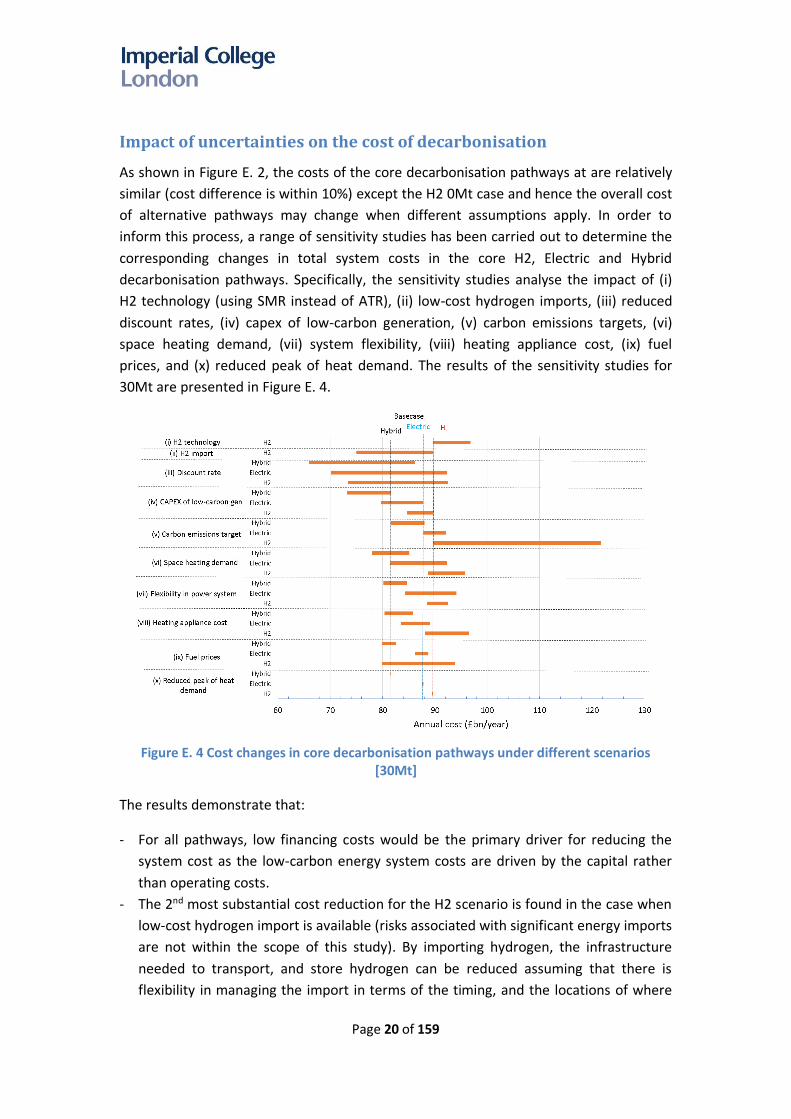
Figure E. 4 Cost changes in core decarbonisation pathways under different scenarios
[30Mt]
The results demonstrate that:
- For all pathways, low financing costs would be the primary driver for reducing the
system cost as the low-carbon energy system costs are driven by the capital rather
than operating costs.
- The 2nd most substantial cost reduction for the H2 scenario is found in the case when
low-cost hydrogen import is available (risks associated with significant energy imports
are not within the scope of this study). By importing hydrogen, the infrastructure
needed to transport, and store hydrogen can be reduced assuming that there is
flexibility in managing the import in terms of the timing, and the locations of where

Page 21 of 159
the hydrogen should be delivered to. Consistently low gas prices could also improve
the viability of a hydrogen pathway, compared to other pathways.
- In all pathways, meeting a stricter carbon target will increase the system costs. While
the increase in costs in Electric and Hybrid is between 4.4 and 7.2 £bn/year, the
increase in cost in the H2 pathway is much more substantial (more than £30bn/year);
this implies that H2 would be the highest cost pathway towards zero carbon.
- A reduction in annual heating demand, driven by improved energy efficiency, could
reduce the total system costs by 0.9 – 6.2 £bn/year. Across the three pathways, the
highest impact of heat demand reduction in the Electric pathway.
- The benefits of system flexibility are highest in the Electric scenario and lowest in the
H2 pathway, as both H2 and Hybrid scenarios involve some inherent cross-vector
flexibility across both gas and electricity systems. Flexibility benefits in this report,
present only the value of additional flexibility beyond cross-vector flexibility that is an
inherent part of the IWES modelling (which co-optimises electricity, gas, hydrogen
and heat systems, simultaneously). This implies that whole-energy system costs
would significantly increase in the absence of cross-vector coordination.
- Cost of H2 pathway is more sensitive towards the fuel prices compared to the Electric
and Hybrid pathway; the volume of gas used in the last two pathways is much lower
compared to the one in the H2 pathway since the heat demand is met primarily by
electric heating (HP) and most of the energy comes from low-carbon resources.
- The impact of the reduction in the peak of heat demand is relatively marginal in all
pathways, as a significant level of system flexibility is assumed, via pre-heating and
thermal storage at a household level. Without this flexibility, the impact on costs of
peak heat demand would be much more significant.
- Across the uncertainties listed above the core Hybrid system (£81.6bn/year) remains
the least-cost solution, followed by Electric pathway (£87.8bn/year) and H2 pathway
(£89.6bn/year). It can, therefore, be concluded that the Hybrid pathway is the most
robust decarbonisation pathway to reach the 30Mt carbon target. There are a few
conditions where an H2 pathway becomes more competitive, i.e. if large-scale and
low-cost imports of hydrogen are available (at £25/MWh), and all other conditions
remain the same, or if gas prices are low (at 39p/therm). The cost of the Electric
pathway is always higher than the cost of Hybrid. The cost of the Electric pathway is
close to the cost of the Hybrid pathway particularly when heating demand is low.
As the impact of different assumptions may get intensified in the zero-carbon cases, the
importance of different parameters on the costs of different decarbonisation pathways
may also change; the results of the sensitivity study for 0Mt cases are shown in Figure E.
5.

Page 22 of 159
Figure E. 5 Comparison between the costs of different decarbonisation pathways under
different scenarios [0Mt]
In most cases, the trends are the same as ones observed in the 30Mt cases with some
exceptions such as:
- The impact of reduced financing costs in the H2 pathway is higher than in the other
pathways. The results are driven by the need for the 0Mt H2 case to have a much
more significant investment in electrolysers and low-carbon generation technologies
compared to the other pathways. This is a contrast to the results of the 30Mt cases
where the highest impact of having a low discount rate is found in the Electric case.
- For the same reason, the impact of reduced capex of low-carbon generation is the
highest in the H2 0Mt case. This is a contrast to the results of the 30Mt case, where
the largest impact is found in the Hybrid pathway.
- The value of system flexibility increases significantly in 0Mt scenarios. However,
additional flexibility is less important in zero emissions H2 pathways given the
presence of electrolysers that can provide system balancing services while generating
hydrogen.
- As indicated in Table E2, the cost of the core Hybrid pathway is the lowest
(£88.0bn/year) compared with Electric pathway (£92.2bn/year) and H2 pathway
(£121.7 bn/year). The cost of the H2 pathway is the highest in most cases, with the
exception of potential low-cost hydrogen imports.
- The cost difference between the Hybrid/Electric and H2 pathway increases compared
to the cost difference between the corresponding pathways in 30Mt cases. In
contrast, the cost differences between the Electric and Hybrid decreases in 0Mt
cases. This is expected since the Hybrid system becomes more dependent on
electrification to decarbonise the heating and gas systems, as less residual emissions

Page 23 of 159
are allowed for in the gas boiler element of the hybrid heat pump.
Since the Hybrid pathway is the least-cost scenario in both the 30Mt and 0Mt cases, it
can be concluded that the Hybrid scenario is the most robust decarbonisation pathway,
although the absolute level of decarbonisation that can be achieved through this
pathway depends on the availability of biogas, and consumer usage of the heat pump
and boiler elements of the hybrid heat pump24.
Alternative heat decarbonisation strategies: district heating and
micro-CHP
Successful implementation of district heating in Denmark (and some other EU countries)
and the potential application of end-use micro-CHP technologies have raised questions
about the contribution these technologies could make to heat decarbonisation
pathways. The results are compared with the core scenarios in the corresponding
pathways. The costs and system implications of implementing these alternative
strategies are presented in Figure E. 6.
Figure E. 6 Annual system cost of different decarbonisation pathways
The key findings from these studies are:
1. National district heating pathways are significantly more costly than other heat
pathways due to the expenditure associated with the deployment of heat
networks.
24 Annual use of the boiler component is around 14% in the 30 Mt scenario and 3% in the 0 Mt scenario
Hydrogen pathways
Electric pathways
Hybrid pathways
Page 24 of 159
The analysis demonstrates that national deployment of district heating incurs a higher
cost than the systems with domestic heating appliances, which is primarily driven by the
cost of deploying heat networks and the cost of connecting consumers to heat networks,
including new assets needed to control heat and the metering in dwellings. On the other
hand, due to economies of scale, the cost of heating devices in the district heating
networks is significantly lower (35%-50%) compared to the cost of domestic heating. In
the Electric pathway, there is also a significant reduction in the capital cost of the
electricity generation driven by a higher COP of industrial HP (4 on average) compared to
the COP of domestic HP (less than 3 on average) but this cost reduction is still lower
compared to the increase in costs associated with heat network deployment and
connection.
While the study provides evidence that national deployment of district heating will not
be cost-effective, local application of district heating in high-heat-density areas could
provide a more cost-effective solution as the cost of heat networks and disruption cost
could be minimised. It is estimated that the cost of urban heat networks is less than 25%25
of the cost of heat networks in non-urban areas while heat demand in urban areas is
estimated around 40% of the total heat demand.
2. Micro-CHP, installed in households, could contribute to reducing the capacity of
centralised electricity generation and network reinforcement.
Small-scale end-use combined heat and power (micro-CHP) can substitute for the
capacity of electric heating appliances, reduce distribution network costs and displace
the capacity of gas-fired plants including hydrogen power generation, while the impact
on RES and the nuclear capacity requirement is marginal. This finding demonstrates that
micro-CHP could provide firm capacity (assuming it is able to be managed to provide
capacity during peak demand) while significantly enhancing generation efficiency, as the
heat produced from thermal electricity generation is not wasted but is used to meet
local heat demand. However, given the assumptions related to the cost of micro-CHP26
and the need for an auxiliary gas / hydrogen boiler, the total cost of the system with
micro-CHP is still marginally higher than the cost of the core Hybrid pathway (but slightly
lower than the Electric scenario). Furthermore, the physical size of the some micro-CHP
technologies may need to be reduced further in order for these to be deployed at
scale27.
Alternative heat decarbonisation strategies: regional scenarios
Deploying hydrogen in the regions where gas terminals are available or in regions with
high energy demand density such as urban areas as alternatives decarbonisation
25 The total length of urban networks is less than 25% of the overall length of distribution networks. 26 Cost of micro-CHP used in the studies is £2500/kW. 27 Micro-CHP based on steel-cell technology is already appropriate for most domestic premises.

Page 25 of 159
pathways, have also been investigated and analysed for the 30Mt and 0Mt carbon
emission cases. Three regional scenarios are considered: (i) Hybrid – H2 North assumes
that the main heating system in the North of GB (Scotland, North of England, North
Wales) is fuelled by hydrogen while the other regions use hybrid heat pumps; (ii) Hybrid
– H2 Urban assumes that hydrogen heating systems are deployed in all urban areas
while other regions use hybrid heat pumps for heating; (iii) Hybrid – Urban DH HP
assumes the use of electric-based district heating with highly-efficient ground-source
HP28. The results are presented in Figure E. 7, and the annual system costs of the regional
scenarios are compared against the costs of non-regional Hybrid systems (the first two
bars in the graph).
Figure E. 7 Costs of alternative Hybrid pathways
Use of hydrogen in Hybrid regional scenarios can reduce demand for low-carbon
generation and reduce the cost of electricity generation at the expense of increased
hydrogen infrastructure operating costs. The results demonstrate that for the 30Mt
case, deployment of hydrogen in the Northern region could be an attractive alternative
to the non-regional scenario; the cost is marginally lower by £0.8bn/year. This implies
that for some regions, hydrogen conversion can be a cost-effective heat decarbonisation
option. This favours regions in close proximity to existing gas terminals, and carbon
storage areas. Towards a zero-carbon energy system, the cost of Hybrid- H2 North [0] is
£6.6bn/year higher than the cost of Hybrid [0] due to the need to use electrolysers and
low-carbon generation technologies to produce hydrogen. The costs of regional Hybrid –
H2 Urban cases, both for 30Mt and 0Mt cases, are higher compared to the cost of the
28 Annual average COP is 4.

Page 26 of 159
non-regional Hybrid system by 3.9 – 13.4 £bn/year. The cost of producing hydrogen in
local district areas is assumed to be 50% higher than the cost of producing hydrogen by
large-scale plants located near gas terminals; this increases the capex of hydrogen
infrastructure in the Hybrid – H2 Urban scenarios.
One of the main barriers to district heating is the high cost of deploying heat networks.
Therefore, the implementation of district heating may be constrained to the high-heat-
density areas, e.g. urban areas. The results of Hybrid – Urban DH HP demonstrate that
the efficiency of industrial HP can reduce the infrastructure cost of electricity generation
compared to the corresponding costs in Hybrid, but the cost of deploying district heating
infrastructure offsets the benefits. Overall, the total costs of Hybrid – Urban DH HP are
2.8 – 4.2 £bn/year higher than the costs of the Hybrid pathways.
These results demonstrate the importance of considering regional diversity in national
level heat decarbonisation decisions, though the cost optimality of this diversity depends
on the desired level of decarbonisation. Converting heat to hydrogen in some regions
could be a cost-effective decision as part of a hybrid national level heat decarbonisation
strategy.
The importance of cross-energy system flexibility and firm low-
carbon generation
As discussed previously, improving energy system flexibility is necessary for enabling
cost-effective integration of low-carbon electricity generation particularly renewables.
Improving flexibility could save around 10 and 16 £bn/year in the 30Mt and 0Mt case
respectively. The flexibility should be provided not only in the electricity system but also
in the gas, heating, and transport systems as there is a strong coupling across these
energy vectors as demonstrated in the studies.
The availability of firm low-carbon resources such as nuclear generation is critical for
fully de-carbonising the energy system29. As the study demonstrates, firm low-carbon
generation is significantly less critical in systems with a less demanding carbon target30.
Given this finding, the analysis was carried out to investigate the possibility of delivering
a zero-carbon energy system without nuclear power. An alternative approach
considering a higher RES capacity is studied with the aim to quantify the RES capacity
needed to meet zero carbon without nuclear. The study demonstrates that it would
feasible to achieve zero-emissions energy system without nuclear generation, subject to
the presence of hydrogen storage and corresponding hydrogen-based power
generation.
29 In a 0Mt scenario CCS technologies for producing hydrogen or power generation cannot be used due to residual carbon emissions unless a capture rate of 100% is assumed.
30 This section hence mostly focuses on 0Mt case.

Page 27 of 159
Figure E. 8 presents the comparison between the optimal generation portfolio for the
Electric 0Mt pathway with and without nuclear generation. The capacity of PV and wind
needed in a zero-carbon Electric system without nuclear plants are 175 GW and 185 GW
respectively, which is above the estimates of UK potential for these technologies31.
Unless the potential level of PV and wind can be increased to such level, the system will
require nuclear to meet the zero-emission target. An alternative solution is to use
hydrogen imports, the system can achieve zero-carbon emissions within the built-
constraint in PV and wind capacity, but it requires a higher capacity of hydrogen-based
power generation.
Figure E. 8 Comparison of the generation portfolio for Electric pathway with and without
nuclear technology
To achieve zero-carbon emissions without firm low-carbon generation, there is a need
for significant long-term energy storage that could be provided by hydrogen. This is in
addition to significant short-term energy system flexibility provided by demand shifting
via pre-heating and thermal storage in homes (50% of potential demand flexibility is
assumed available). As shown in Figure E. 9(a), during periods of high RES output, the
excess energy is converted into hydrogen by electrolysers (“Power-to-Gas”). This drives
the need for investment in electrolysers32 to enhance the utilisation of RES. Energy in the
form of hydrogen can then be stored across long time horizons as losses in hydrogen
storage are assumed to be minor and not time dependent. Electrolysers can also provide
balancing services during high RES output, and therefore, reduce the need for these
services from other sources (generation, demand-side response, storage, etc.), though
31 150 GW for PV and 120 GW for wind 32 15 GW of electrolysers is proposed by IWES in the Elec [0] No nuclear, high RES case.

Page 28 of 159
this role absorbs just 5% of total electricity over the year33. During low RES output, the
stored energy can be used to produce electricity via hydrogen-based power generation.
Hence the capacity of hydrogen-based CCGT increases significantly - from 23 GW in the
system with nuclear to 51 GW in the system without nuclear. It can be concluded that
“Power-to-Gas” and hydrogen-based generation can substitute nuclear generation. It is
important to note that electrolysers (as part of the “Power-to-Gas” system), due to
higher costs, are not selected by the model in the core Electric pathways when nuclear
generation is available, as other technologies, such as demand-side response and energy
storage technologies are able to provide system flexibility services at lower cost. It is
important to highlight that hydrogen-based CCGTs and OCGTs can also provide system
balancing which facilitates the cost-effective integration of other low-carbon generation
such as renewables and nuclear.
(a) Elec [0] no nuclear, high RES case
33 Electrolysers also provide grid-balancing services particularly when the system is less flexible (e.g. in H2 0Mt case). In this case, electrolysers are used to save the excess of renewable energy in the form of hydrogen. Since there are losses associated with this process, it is carried out only when it is necessary.

Page 29 of 159
(b) Elec [0] core scenario
IWL: baseload including Industrial and Commercial load, EV: Electric Vehicle, SA: Smart Appliances,
HP: Heat Pump, RH: Resistive Heating, P2G: Electrolysers
Figure E. 9 The role of electrolysers, hydrogen storage and generation in balancing the system with large penetration of renewables and the use of biogas for peaking plants
Figure E. 9(b) shows the hourly generation output and load profiles for the same period
in the Electric 0Mt core scenario. The availability of nuclear reduces the need for
hydrogen-based CCGT and other low-carbon generation such as wind and PV as shown
in Figure E. 8.
Given the cost assumptions used in the study, the scenario without nuclear will cost
around £10bn/year more than the scenario with nuclear. The comparison between the
system costs of the core Electric 0Mt case with and without nuclear is shown in Figure E.
10.

Page 30 of 159
Figure E. 10 System costs of the Electric pathway with and without nuclear technology
The results of the study demonstrate that in the absence of firm low-carbon generation
such as nuclear, the system would require long-term storage that could be supplied by
hydrogen through investment in the hydrogen electrolysers and storage. The capacities
of hydrogen production plant, hydrogen networks and storage are optimised and
tailored to system needs in order to minimise the overall system cost.
To achieve zero-carbon emissions without nuclear generation, there is a need for 3.6
TWh hydrogen energy storage (Figure E. 11), that can provide both support in the short-
term energy balancing and long-term storage. The volume of hydrogen storage needed
is around 1100 mcm, which, for context, is around 30% of the volume of the recently
closed Rough gas storage facility. The annuitized investment cost of the hydrogen
storage across GB in this scenario is around £3.2 bn/year.

Page 31 of 159
Figure E. 11 Comparison of the hydrogen storage requirement in Electric 0Mt cases
The need for investment in hydrogen infrastructure (production plant, network, and
storage) could be reduced by importing hydrogen rather than producing it in GB.
Importing hydrogen reduces demand for long-term storage and Power-to-Gas schemes.
The interaction between thermal and electricity storage
Other forms of energy storage investigated in this study include thermal energy storage
(TES) and electricity storage. The IWES model optimised the portfolio and size of the
energy storage system considering the technical and cost and characteristics of each
storage technology. Studies have also been carried out investigating the correlation
between the thermal storage and electricity storage; the results are presented in Figure
E. 12.

Page 32 of 159
Figure E. 12 Correlation between TES and electricity storage
The modelling results demonstrate that in the absence of thermal storage and other
forms of flexibility, there would be a need for more than 55 GW new electricity storage34
in the Electric scenario; however, if 58 GWth of TES (1.7 kWth/household) and preheating
(more than 100 GWth) are available, the need for new electricity storage reduces to
below 10 GW, since the cost of thermal storage (e.g. hot water tank, oil or phase-
change-material based thermal storage) is considerably lower than the cost of electricity
storage while the preheating is assumed to be applied at low cost.
Impact of future development of gas-based hydrogen production
technologies
Steam Methane Reforming (SMR) is currently a mature technology for producing
hydrogen from natural gas. In the future, this technology could be substituted by Auto
Thermal Reforming (ATR), which is expected to have superior performance in terms of
cost, energy efficiency and carbon capture rate35. The cost performance difference
between the two technologies in the H2 30Mt pathways is analysed, and the results are
presented in Figure E. 13.
Application of ATR as the primary technology for production of hydrogen in the 30Mt
case would reduce system costs by £7.2bn/year compared to the case with SMR. The
cost reduction is enabled by (i) savings in low-carbon electricity generation capex due to
reduced requirement for decarbonising electricity within a fixed emissions constraint, as
the emissions from the gas sector is lower than compared with the SMR case; (ii) a
34 Total storage capacity is 110 GWh. 35 See Element Energy (2018) Hydrogen Infrastructure: Summary of Technical Evidence

Page 33 of 159
reduction in the capex of hydrogen infrastructure as the cost of ATR is lower than SMR;
and (iii) a substantial reduction in the operating costs as the efficiency of ATR (89%) is
higher than SMR (75%).
Figure E. 13 Cost performance of H2 pathways based on SMR and ATR
However, significant increases in the cost of the H2 pathway in the zero-carbon scenario
are driven by the need to produce hydrogen via electrolysis. In this context, the impact
of possible technology enhancements in capturing the carbon emissions of Auto Thermal
Reformer (ATR) from 96% (the value used in the base case) to 100% with a marginal
increase (10%) in cost has been analysed. This improvement would enable the use of
ATR in the zero-carbon scenario, which would significantly reduce the cost of the H2
scenario. The cost performance of the H2 pathway in 0Mt case with electrolysers and
enhanced ATR is compared in Figure E. 14.

Page 34 of 159
Figure E. 14 Value of enhancing the capture rate of ATR for a zero-carbon system
Enhancing the capture rate of ATR would reduce the cost of H2 0Mt pathway from
£121.7bn/year to £92.5bn/year while enabling zero emissions target to be achieved.
Since the cost of ATR is also lower than electrolysers, the cost of hydrogen infrastructure
would also reduce as well as the cost of low-carbon electricity generation required to
produce hydrogen via electrolysis. The use of gas would increase the operating cost of
the H2 pathway, offsetting some of the savings obtained in the reduction of hydrogen
and electricity infrastructure capex. If a zero-emissions ATR could be developed, this
would make hydrogen scenario significantly more cost effective: the cost of H2 0Mt
pathway with zero-emissions ATR would be only marginally higher than the cost of Elec
0Mt pathway. Therefore, if a future gas-based hydrogen production technology was able
to achieve zero emissions (i.e. capture rate of CCS is towards 100%) at limited additional
cost, the system costs of the hydrogen pathway would be comparable to alternative
pathways for a zero-emissions energy system.
Impact of improved energy efficiency and climate change
The optimal choice of decarbonising heat may depend on the level of heat demand in
the future which could be influenced by many factors, e.g. improved housing insulation
and climate change. In this context, the system costs of the core scenarios are compared
with the costs of two scenarios with lower heating demand. The first, second, and third
sets of three bars in Figure E. 15 correspond to (i) core scenario, (ii) low domestic
heating demand scenario, and (iii) low domestic heating demand with climate change
adjustment (CCA). The corresponding annual domestic heat demand including both
space-heating and water-heating demand used in these three scenarios is (i) 349 TWhth,
(ii) 290 TWhth, and (iii) 234 TWhth. The last scenario assumes a 2C increase in the UK

Page 35 of 159
temperature in 2050.36 The studies were carried out for all three main pathways for 0Mt
cases.
Figure E. 15 Impact of the reduction in heat demand on the system annual costs
The results demonstrate that the annual system costs are lower when domestic heating
demand is reduced, though it is worth noting that the results exclude the costs
associated with reducing this demand (e.g. investment cost for improving thermal
insulation and using the smart-energy system). In addition to demand reductions the
results for the “Low demand with CCA” are influenced by the assumed higher annual
average temperature in this pathway, resulting in a higher average COP for heat pumps
in the Electric and Hybrid pathways. Consequently, this reduces the infrastructure
requirements and associated costs. The impact on the power generation capacity
requirement is shown in Figure E. 16.
For the Electric and Hybrid pathways, comparing the generation capacity proposed for
the core scenario and Low demand with CCA, there is around an 8-9 GW reduction in the
capacity of nuclear plant. A substantial 17 GW reduction of peaking capacity (OCGT) in
the Electric pathway; in general, there is a substantial reduction in the power generation
capacity across all pathways due to a reduction in the heating demand.
36 The core scenarios use historical temperature data with a few consecutive days of modified demand to simulate extreme weather events, i.e. very cold days with low output of renewable energy.

Page 36 of 159
Figure E. 16 Impact of heating demand reduction on the optimal generation mixes
The costs of the H2 pathways are still the highest in these zero-emissions scenarios, and
the least-cost solutions for all scenarios are still the Hybrid pathways although the cost
difference between the Electric and Hybrid pathways becomes less with reduced heat
demand. The results are not unexpected since increased energy efficiency or increased
temperature will reduce peak heat demand and the corresponding benefits of HHPs.
The ability of the existing gas distribution system to transport
hydrogen
Modelling was carried out to investigate the technical capability of the existing gas
distribution networks to transport hydrogen instead of natural gas, to meet the peak
heat demand. Distribution networks operating at different low, medium and high-
pressure levels were examined. The results demonstrate that the transportation of
hydrogen does not have a significant impact on the pressure profiles for low and
medium pressure gas distribution networks, nor their capability to meet peak energy
demands. However, in high-pressure networks, the ‘linepack’ (i.e. the volume of gas that
can be stored in a gas pipeline) plays an important role in meeting the energy demand
during peak conditions. The lower density of hydrogen compared to natural gas would
reduce the available linepack in the high-pressure networks and constrain their energy
supply capability. Consequently, a small amount of localised hydrogen storage facilities
would be required to enable the distribution networks to transport hydrogen to meet
the peak of heat demand. The modelling extrapolates additional hydrogen network
storage network requirements across the GB gas distribution system, based on the
amount of hydrogen storage capacity required in high-pressure hydrogen distribution

Page 37 of 159
test networks that were modelled37. The results indicate that in order to enable the
existing gas distribution networks to transport hydrogen during peak conditions,
between 131 GWh to 333 GWh of hydrogen storage would be required38, which would
increase the cost of H2 pathway for approximately £0.35bn/year to £0.61bn/year,
equivalent to 0.4% of the total costs of the hydrogen pathway39.
Key findings
Based on the cost performance of different pathways with the 30Mt and 0Mt carbon
target40, the cost of each pathway is presented in merit order in Table E. 2.
Table E. 2 Cost performance of different heat decarbonisation pathways
30Mt scenarios Cost (£bn/year) 0Mt scenarios Cost (£bn/year)
Hybrid - H2 North 80.8 Hybrid 88.0
Hybrid 81.6 Hybrid - Urban DH HP 90.8
Hybrid - H2 Urban 85.4 Hybrid + micro-CHP 91.4
Hybrid - Urban DH HP 85.8 Elec 92.2
Hybrid + micro-CHP 87.2 Hybrid - H2 North 94.7
Elec 87.8 Elec+DH 97.7
H2 89.6
Hybrid - H2 Urban 101.4
Elec+DH 94.3
H2 121.7
H2+DH 111.6
H2+DH 142.2
For the 10Mt cases, the annual system costs are £84.8bn/year for the Hybrid case,
£89.5bn/year for the Electric case, and £90.2bn/year for the Hydrogen case.
It can be concluded that:
- The Hybrid pathway is identified as the most cost-effective decarbonisation pathway,
although the costs of the core decarbonisation pathways are relatively similar (the cost
difference is within 10%). Though it is worth noting that given the uncertainties
involved, the ranking may change when different assumptions apply.
- Systems with lower carbon emission targets will lead to higher costs, though the
absolute level of cost depends on the emissions reduction target. In all scenarios,
further emission abatement, from 30Mt to 10Mt, is available at limited additional cost
(the increased cost is between by 0.6 - 3.2 £bn/year). However, this will change when
37 Based on modelling results of high-pressure test networks and peak heat demand for various Local Distribution Zones (LDZ) across GB, the regression model was applied to estimate the required hydrogen storage capacity. 38 In addition to the investment needed in centralised hydrogen storage, e.g. salt-cavern storage. 39 The cost of distributed storage is included in the costs of all H2 scenarios. 40 10 Mt cases were only performed for the core scenarios. In these cases, the Hybrid pathway is the
least-cost solution followed by the Electric and the H2 pathway.

Page 38 of 159
moving from 10Mt to 0 Mt, with the cost further increases by £31.5bn/year in the
hydrogen scenario, compared to £2.7bn/year in the electric scenario.
- Electric and Hybrid pathways provide more optionality towards deep levels of
decarbonisation compared to the H2 pathway, given the shift in hydrogen production
from gas (ATRs) to electricity (electrolysers), which significantly increases the cost of
hydrogen infrastructure.
- Regional scenarios for deploying hydrogen and district heating are more attractive than
national deployment for these specific solutions. In some cases, regional heat
decarbonisation choices – such as hydrogen in the North of GB, or district heating in
heat dense areas - within a wider national system can reduce overall costs.
- Technologies such as micro-CHP can provide alternatives to electric heating and
improve cross-energy flexibility between electricity and gas systems.
- There are significant uncertainties in the assumptions underpinning all scenarios,
providing no clear lowest cost solution across the three core decarbonisation
pathways.
Considering the uncertainty across different heat decarbonisation pathways and
emissions targets, “low/no regrets”41 capacities of low-carbon generation technologies
across different pathways and emissions targets have been derived from the modelling
results. It indicates that there will be a minimum requirement of 5 GW of nuclear, 74 GW
of wind, and 3 GW of H2 CCGT across all pathways. Additional electricity generation
capacity will need to be built as the optimal generation portfolio will depend on many
factors such as costs, system flexibility, selected decarbonisation pathway and the
carbon target.
A range of sensitivity studies has also been carried out to assess the impact of different
assumptions on each decarbonisation scenario and its associated costs. The sensitivity
studies consider the influence of different discount rates, system flexibility, carbon
emissions targets, capex of low-carbon generation, heating demands, etc. In most of the
cases considered in the sensitivity analysis, the Hybrid scenario is identified as the least-
cost decarbonisation pathway; although the volume of gas reduces significantly, the
value of existing gas infrastructure increases significantly by providing flexibility and
reducing significantly investment in electricity infrastructure. The Hybrid pathway is
generally more resilient to the sensitivities included in this analysis while the H2 and
Electric pathways would cause higher levels of disruption to households (requiring both
building upgrades and disruptions related to network reinforcements).
In summary, the key findings of the modelling carried out are as follows:
41 Low/no regrets capacity is defined as the capacity that will be needed irrespective of the decarbonisation pathway adopted in the future.

Page 39 of 159
• Towards a zero-carbon energy system, the cost-effective decarbonisation of heat may
require electrification
o Unless carbon capture rates involved in the production of hydrogen via gas
reforming can reach close to 100%, then decarbonising via hydrogen would
require significant investment in zero-carbon electricity generation in order to
produce hydrogen via electrolysis, which increases the costs of hydrogen scenario
significantly above hybrid and electric pathways.
o Technology improvement in both carbon capture rates and efficiencies of gas-
based hydrogen production technologies would significantly reduce the cost of
hydrogen pathways, particularly in a 0Mt scenario.
• Energy efficiency is of key importance
o Reducing heat demand by improving energy efficiency of buildings can reduce
system costs across all pathways.
• Towards a zero-carbon energy system, overall system costs will be dominated by the
capital expenditure rather than operating costs
o Any measures that may reduce the capex (e.g. lower financing cost) will have a
significant impact
o Energy system pathways will be less sensitive than today’s energy systems to fuel
price variations, particularly in the Hybrid and Electric pathways.
• System flexibility is of key importance for cost-effective energy system
decarbonisation
o In this context, the modelling demonstrated that the lack of additional sources
flexibility would further increase system costs by additional £16 billion per year42.
The study demonstrates that having 50% of potential flexibility would already
capture a significant proportion (70%-85%) of the benefits. As the benefits are
non-linear, initial improvements in flexibility have the highest value; beyond 50%
flexibility the marginal value of additional flexibility reduces.
o Clearly, co-ordinating system flexibility across electricity and gas systems can
reduce system costs, e.g. (i) the use of gas to supply heat during peak demand
conditions significantly reduces investment in electricity system infrastructure (ii)
hydrogen could be stored over long-term time horizons and hence used in the
power system to reduce the need for firm low carbon generation (e.g. nuclear);
(iii) household level flexibility around heat demand, facilitated by thermal energy
storage and application of preheating, would enhance the utilisation of renewable
energy resources and significantly reduce system capacity requirements.
o Stronger planning coordination between electricity, gas and heating systems is
42 The maximum value of additional flexibility was obtained in the Electric 0Mt pathway, while the value of additional flexibility in other scenarios is lower as significant flexibility is provided through coordination across different energy vectors. The value of additional flexibility varies across different pathways and carbon targets (presented in section 3.5.1).

Page 40 of 159
needed to minimise whole-system costs.
o When electrolysers are needed (e.g. to produce hydrogen), electrolysers can
provide short-term grid balancing services following the output of renewables.
However, such flexibility can also be provided by demand response and storage
hence the decision to invest in electrolysers is not primarily driven by the need for
grid balancing but by converting energy from low-carbon electricity generation to
hydrogen which can then be stored more cost-effectively. Electrolysers have
important role in H2 0Mt case but are less critical in other pathways.
• Energy storage can reduce system capacity requirements and facilitate the cost-
effective deployment of renewables.
• Energy storage can be used to improve load factors of baseload power generation
and hydrogen production plants; the cost of storage is typically lower than the
capex of baseload plant, and therefore it can provide capacity at lower cost. The
modelling results demonstrate that hydrogen storage is essential to maintain
steady production in gas-reforming plants that produce hydrogen43. This can
reduce the need for hydrogen production capacity and its associated cost and
provide cost-effective both short and long-term energy storage as a supplement or
an alternative to other energy storage technologies (e.g. electricity storage and
thermal storage). Whilst a hydrogen transmission network provides significant
‘linepack’ storage of hydrogen, hydrogen storage can complement this by
providing both short and long-term energy balancing. This can substitute for firm
low-carbon generation, which will facilitate more effective integration of RES into
the energy system. The model chooses to invest around £6bn/year in hydrogen
storage in a H2 [30] Mt scenario, which is lower cost than scenarios with lower
amounts of hydrogen storage.
o The modelling results demonstrate that in the absence of thermal storage and
other flexibility resources, there would be a need for more than 55 GW additional
electricity storage in the Electric scenario; however, if 58 GWth of TES (1.7
kWth/household) and preheating (more than 100 GWth) are available, the need for
new electricity storage reduces to below 10 GW, since the cost of preheating and
thermal storage (e.g. hot water tank, phase-change-material based thermal
storage) is lower than the cost of electricity storage.
• Importing low-cost hydrogen could potentially make the H2 pathway cost competitive
against electrification pathways; although producing hydrogen at the costs assumed
in this analysis would require a significant reduction in the cost of electrolysis and
shipping hydrogen. Imports of hydrogen could also reduce the need for UK based
hydrogen storage.
43 Current gas-reforming technology operates at steady output. This was therefore included as an assumption in the model.

Page 41 of 159
• Economies of scale of investment are also important for achieving minimum overall
cost. The modelling assumes that both electricity and hydrogen is produced on a
centralised, rather than a distributed basis. More localised production would result in
lower economies of scale, increasing system costs.
• Gas network modelling suggests that additional network level storage of distributed
hydrogen (131 – 333 GWh) is required to enable transport of hydrogen through high-
pressure distribution gas networks. This would increase the cost of H2 pathway for
approximately £0.35bn/year to £0.61bn/year. While the total volume required is
relatively small, the distribution of these storages is important for consideration.
Therefore, this investment cost is in addition to significant investment in large-scale
storage facilities in the H2 scenarios.
Recommendations
A set of recommendations are outlined below, based on the modelling results and
analysis carried out in this study.
Further analysis
In order to provide an in-depth understanding of the transition towards low-carbon
heat, a number of areas may warrant further investigation. These could include:
• Detailed analysis of different types of buildings considering typical heat requirements,
levels of insulation, the role of thermal storage, etc. Following this, a further
assessment of corresponding system performance and costs could be made.
• Further investigation of alternative decarbonisation pathways that involve diversified
(“patchwork”) heating solutions across different regions in the UK, and the impact
these could have on national low-carbon heating choices. In the context of heat-
sector decarbonisation it may be appropriate to investigate if the concept of levelized
cost of end use heat technologies could be introduced to inform corresponding policy
development.
• Development of robust least-worst heat decarbonisation pathways and
corresponding policies, while considering explicitly a full range of technologies and
system uncertainties.
• The resilience of the future energy systems considering high impact events such as
extreme weather conditions, shortage of gas supply, etc.
• Role, value and business cases of emerging technologies such as micro-CHP, Phase
Change Material-based thermal energy storage, co-optimisation of energy for cooling
and heating, research into long-term thermal energy storage technologies.
• Assessing the significance of the integration of transport and heat sectors through the
vehicle-to-home / vehicle-to-grid concepts, and the impact on the need for thermal
storage.
• Investigation into the operation and costs of managing the gas grid with significantly
reduced flows of gas (i.e. in the hybrid heat pump scenarios).

Page 42 of 159
• Further research into the implications of additional energy efficiency measures,
beyond what was assumed in this study, applied across all heat decarbonisation
pathways.
• Investigation in greater detail of the scope for H2 imports; this should include
consideration of costs of solar generation, electrolysers, water production, etc.,
marine transport, storage (ammonia versus liquid H2) and different locations (North
Africa, Middle East, South Africa, Australia).
• Further research related to the provision of system inertia is needed to investigate
the impact on the optimal portfolio of generation technologies, particularly in 0 Mt
case, as the provision of synthetic inertia (e.g. by wind generation) could reduce the
optimal volume of nuclear, while on the other hand, coordinated de-loading of
nuclear generation during low demand and high renewable output conditions would
reduce the size of the largest loss and hence enhance the value of nuclear generation.
Decarbonisation of electricity supply and enhancement of system flexibility
The studies demonstrate that the decarbonisation of electricity generation and
improvement of system flexibility are essential irrespective of the adopted heat
decarbonisation strategy. As the present renewable capacity, around 40 GW in total, is
significantly lower than the no-regret capacity, this implies that the decarbonisation of
electricity supply should be continued. In the short term, the deployment of low-carbon
generation can focus on renewable power. In the medium and long-term, firm low-
carbon capacity should be installed to meet low emissions carbon targets. Technologies
such as nuclear, CCS, hydrogen-based CCGT/OCGT etc., should be considered. Increased
penetration of low-carbon generation capacity should be accompanied with increased
flexibility in the system to minimise the system integration costs. Further knowledge and
practical experience should be gained by trialling smart control of demand systems to
enhance the system flexibility.
Policy development for heat decarbonisation
At present, there is a large-scale programme underway for the decarbonisation of the
electricity supply sector (i.e. a support mechanism for investment in low carbon
generation). In order to facilitate investment in low-carbon heating appliances such as
hydrogen boilers, electric/hybrid heat pumps, micro-CHP, etc., it would be important to
review and develop further policy guidance and/or financial incentives including
Renewable Heat Incentive (RHI)44 to individual end-users and/or energy communities to
encourage and reward investment in low-carbon heating technologies. Furthermore, the
price of electricity reflects the carbon content of the fuel mix, which is not the case for
household currently on fossil fuel-based heating systems, so carbon price for heat
44 RHI provides financial incentive to promote the use of renewable heat including heat pumps.

Page 43 of 159
should be considered. In this context, it will be important to investigate the CO2
reductions that could be achieved from demand-side focussed strategies, e.g. radical
building energy efficiency programs.
Market design for flexibility
As demonstrated in this study, cross-energy system flexibility will be critical for
facilitating a cost-effective transition to a low-carbon energy system (i.e. a reduction in
investment in low carbon generation and energy conversion technologies, a reduction in
system operating costs, a reduction in investment in system capacity needed to meet
the peak demand). In the electricity sector, there are several emerging markets focusing
on new flexibility products (such as fast frequency response, demand-response reserve
services, etc.). These initiatives should be extended through the development of cost-
reflective flexibility markets45 with appropriate spatial and temporal resolutions, that
would link all energy vectors and facilitate competition between alternative solutions on
a level playing field.
Furthermore, as demonstrated in the modelling, flexibility technologies and systems can
reduce the amount of low-carbon generation needed to meet the carbon targets.
However, suitable remuneration mechanisms for this value stream do not exist in the
current market (and are not considered in the Electricity Market Reform). Such
mechanisms should be developed to allow new flexible technologies to access revenues
associated with a reduction in investment in low carbon generation through establishing
the link between energy market and low-carbon agenda.
Pilot trials
One of the key conclusions from the studies carried out is that none of the heat
decarbonisation pathways can be excluded as options for large-scale deployment, due to
the proximity of overall system costs across the pathways within a significant level of
uncertainty. Therefore, the focus of any action should be to address
uncertainties. Knowledge and experience that will be gained from deployment at scale
(i.e. 10,000s of households) will provide critical insights into the strengths and
weaknesses of alternative approaches to heat decarbonisation and the technologies
involved. Hence consideration should be given to a programme of technology
deployment on a pilot trial basis. These initiatives should be designed to encompass all
aspects of deployment - from production through to end-users - while including all types
of representative buildings within the UK.
45 This is coherent with the recommendation in the Pöyry and Imperial College’s report to the CCC: “Roadmap for Flexibility Services to 2030”, May 2017.

Page 44 of 159
Carbon emission targets for energy
The studies illustrate the impact of reducing carbon emissions from energy from 30Mt to
0Mt – without decarbonisation of the heating system, residual emissions could be over
100 MtCO2, which is incompatible with the UK’s 2050 target. In the long-term, reducing
energy system emissions to zero may be required to support other sectors that cannot
achieve their share of the required greenhouse gas reductions. The consequence of this
would be to substantially reduce natural gas-based technologies such as gas reforming
and gas generation and would, therefore, require considerably more zero-carbon
electricity generation technologies such as nuclear power and renewables, combined
with energy storage. However, progress with importing hydrogen at low costs, or
improving the efficiencies and carbon capture rates of gas reforming technologies could
mitigate the need to build additional low-carbon electricity generation. This hydrogen
production options warrant further investigation.
Hydrogen production demonstration plants
The two hydrogen production technologies for large-scale deployment are currently gas
reforming and electrolysis. Although there is considerable experience of gas reforming it
is limited to industrial applications. There is insufficient experience of electrolysis. In
both cases, there is considerable uncertainty in terms of costs and performance,
particularly for large-scale deployment. It would be informative to commit to build gas
reforming and electrolysis demonstration plants within the UK to enable experience to
be gained prior to making decisions on large-scale deployment.

Page 45 of 159
Chapter 1. Introduction
1.1 Context
The heat sector accounts for more than half of the UK’s energy consumption and
contributes to more than 30% of the total carbon emissions. Achieving the UK’s long-
term climate targets will require decarbonisation of electricity, gas, and heat in a
coordinated manner. A strategic decision on both gas and heat decarbonisation
pathways will require an in-depth understanding of the techno-economic and
environmental characteristics of these pathways.
Addressing the challenges related to decarbonisation of gas and heat, the Committee on
Climate Change (CCC) has identified multiple decarbonisation pathways for low-carbon
heating as proposed in the CCC’s October 2016 report, “Next Steps for UK Heat Policy”46.
Three central pathways have been identified: i.e. (i) by ‘greening’ the gas supply by
shifting to low-carbon hydrogen (H2), (ii) electrification of heat supported by low-carbon
power generation, or (iii) by potential hybrid solutions, with the bulk of heat demand,
met by electricity, and peak demands met by green gas47. Each pathway brings
significant challenges, and the CCC concluded that it was unclear whether there is a
dominant low-carbon heating solution for the UK, and what the implications are on the
future infrastructure requirements and operational coordination across UK energy
systems.
Whichever portfolio of technological options for gas and heat decarbonisation prevails in
the future, the interaction between various energy vectors – electricity, heat,
natural/biogas and hydrogen – will be critical for the cost-effective decarbonisation of
the energy system. A higher degree of integration between electricity and other energy
vectors, especially heat, presents novel and unique opportunities to make use of cross-
vector flexibility to support the integration of low-carbon generation technologies and
the potential to reduce the cost of decarbonisation. The interactions across different
energy vectors are also likely to affect the choice of technologies and the optimal
portfolio of energy infrastructure. This integrated approach will improve the flexibility
across different energy vectors, which can substantially reduce the cost of
decarbonisation and enhance the integration of low-carbon generation technologies into
the electricity system, as demonstrated in several recent studies of the future UK power
46 Available at: https://www.theccc.org.uk/wp-content/uploads/2016/10/Next-steps-for-UK-heat-policy-Committee-on-Climate-Change-October-2016.pdf
47 A bioenergy focused pathway was not considered a core option, as the CCC’s 2011 Bioenergy Review suggested a limit of around 135 TWh of primary bioenergy that could be available to the UK power and gas systems.

Page 46 of 159
sector48,49. Gas decarbonisation through hydrogen may also enable vast quantities of
energy to be stored cost-effectively across seasons, which could significantly reduce the
system integration cost of variable renewable sources.
As the energy system progresses towards ever more ambitious carbon targets, increased
interaction between energy vectors will become more important. In this context, whole-
energy system modelling will be central for capturing the complexities of different
energy sub-systems as well as specific features of a range of emerging energy conversion
and storage technologies (e.g. gas storage, thermal storage, hybrid heat pumps,
combined heat and power plant, fuel cells etc.) that would link energy vectors and
provide flexibility. Analysing multi-vector energy systems at sufficient temporal and
spatial granularity will be essential for assessing the cost-effectiveness of alternative
decarbonisation pathways. Furthermore, multi-vector decarbonisation will also need to
adequately consider the synergies and conflicts between the local/district level and
national level infrastructure requirements. In this context, comprehensive analyses have
been undertaken across multiple energy vectors in order to provide an in-depth
understanding of the interactions between decarbonised electricity, gas and heating
systems, as well as to identify and understand the key uncertainties that affect decisions
around low-carbon heat to 2050.
1.2 Key objectives
This project focuses on understanding and quantifying the impact of long-term cost
drivers of decarbonising the heat sector. The specific objectives of the project are to:
- Understand the implications of alternative heat decarbonisation pathways on
electricity and gas infrastructures in the UK energy system in 2050 by:
o Analysing the interactions between the electricity and heat systems (including
various forms of storage)
o Optimising the interactions across different energy vectors to maximise whole-
system benefits;
- Understand the economic performance and drivers of various pathways by:
o Comparing the whole system costs of alternative heat decarbonisation scenarios
in 2050, and beyond towards a zero-emissions energy system. For example,
comparing the costs of retaining gas distribution networks that are re-purposed
for transporting hydrogen, against reinforcing the electricity grid under various
low-carbon heating scenarios;
48 G. Strbac, M. Aunedi, D. Pudjianto, F. Teng, P. Djapic, R. Druce, A. Carmel, and K. Borkowski, “Value of Flexibility in a Decarbonised Grid and System Externalities of Low-Carbon Generation Technologies,” Imperial College London and NERA Economic Consulting report for the Climate Change Committee, 2015.
49 D. Sanders, A. Hart, M. Ravishankar, G. Strbac, M. Aunedi, D. Pudjianto, and J. Brunert, “An analysis of electricity system flexibility for Great Britain,” Report BEIS, 2016.
Page 47 of 159
o Analysing the impact of uncertainties in technologies and costs;
- Provide fundamental evidence to support the development of policies for
decarbonising heating and the electricity system.
Comprehensive studies have been carried out to quantify the investment and
operational requirements as well as the costs of alternative heat decarbonisation
pathways for a representative energy system for Great Britain in 2050. These studies
were carried out in the context of related activities in this area, including the on-going
research carried out by Department for Business, Energy & Industrial Strategy (BEIS) on
Heat and Strategic Options, research into the costs of future heat infrastructure for the
National Infrastructure Commission50, Network Innovation Competition (NIC) trials, etc.
1.3 Scope of studies
The CCC’s approach to low-carbon heat is presented in Figure 1-1. The scope of this
particular study includes quantification of the system costs of different heat
decarbonisation pathways, consistent with the CCC’s approach to low-carbon heat. The
CCC’s previous analysis has identified that converting all off-gas grid homes and some
direct electric heating to heat pumps, representing 18% of households51, and 13% of
households in urban areas to district heating is cost-effective. This modelling, therefore,
considers the costs of converting the remaining 71% of households to a low-carbon
heating technology. The studies focus on:
- Cost performance of each decarbonisation pathway and cross-cutting analysis across
pathways;
- Interaction and optimal capacity portfolios of power system infrastructure
(generation, electricity network, electricity storage), hydrogen infrastructure
(production capacity, hydrogen network, storage), carbon capture and storage
infrastructure and heating infrastructure;
- Impact of uncertainties in key modelling assumptions and input parameters;
- Role and benefits of enabling technologies that can improve system flexibility across
all energy vectors and reduce emissions;
- Impact of energy efficiency;
- Technical feasibility of transporting hydrogen in the existing gas distribution
infrastructure.
50 Element Energy and E4tech,” Cost analysis of future heat infrastructure,” a report for National Infrastructure Commission, March 2018.
51 Assuming 34.3m households by 2050

Page 48 of 159
Figure 1-1 Low-regrets measures and the remaining challenge for existing buildings on the
gas grid52
The analysis is based on an optimised system constructed by the IWES model, which
assumes that full coordination across all system components can be achieved. This will
require further development of appropriate regulatory and commercial frameworks as well
as cooperation across all market stakeholders and deployment of appropriate technologies
and control systems necessary to enable cost effective decarbonisation of the GB energy
system, which is beyond the scope of this report.
A broad spectrum of studies has been carried out to optimise the future investment and
operation of the Great Britain (GB) system53 focusing on three heat decarbonisation
pathways: H2, Electric and Hybrid systems. The study uses future (2050) annual system
energy demands of domestic and non-domestic sectors provided by the CCC:
• Total annual non-heat and non-transport electricity demand: 367 TWh;
• Total heat energy demand: 633 TWh;
• Total transport-related-electricity demand: 111 TWh.
The composition of the energy demand used in the study is summarised in Figure 1-2.
52 CCC (2016) Next Steps for UK Heat Policy 53 A 14-regions model is used in these studies; the system is described in Appendix F.

Page 49 of 159
Figure 1-2 Composition of energy demand
Sensitivity studies have been performed on the three core decarbonisation pathways,
including:
- Carbon targets: 30, 10, and 0Mt CO2/year;
- Impact of heat demand reductions driven by energy efficiency improvements in the
building stock and climate;
- Impact on the core scenarios of the use of district heating, and micro-CHP
technologies,
- Regional scenarios
- Reduced financing costs
- Low-carbon power generation capex;
- Fuel cost;
- Hydrogen import;
- Hydrogen production technologies: SMR, ATR, electrolysers;
- System flexibility which is provided by:
o Electric system: demand response (including from electrolysers), electricity
storage, Interconnectors;
o Hydrogen storage including long-term and distributed storage;
o Thermal Energy Storage (TES) including preheating, domestic and district heating
thermal storage.
- Constraint on the low-carbon resources including nuclear;
- Availability of technology;
- Heating technologies (e.g. HP/RH only vs optimised HP and RH).
- Interactions between gas and electricity systems.
Discussions of the results and the analysis can be found in Chapter 2 – 4.
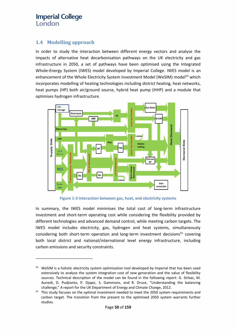
Page 50 of 159
1.4 Modelling approach
In order to study the interaction between different energy vectors and analyse the
impacts of alternative heat decarbonisation pathways on the UK electricity and gas
infrastructure in 2050, a set of pathways have been optimised using the Integrated
Whole-Energy System (IWES) model developed by Imperial College. IWES model is an
enhancement of the Whole Electricity System Investment Model (WeSIM) model54 which
incorporates modelling of heating technologies including district heating, heat networks,
heat pumps (HP) both air/ground source, hybrid heat pump (HHP) and a module that
optimises hydrogen infrastructure.
Figure 1-3 Interaction between gas, heat, and electricity systems
In summary, the IWES model minimises the total cost of long-term infrastructure
investment and short-term operating cost while considering the flexibility provided by
different technologies and advanced demand control, while meeting carbon targets. The
IWES model includes electricity, gas, hydrogen and heat systems, simultaneously
considering both short-term operation and long-term investment decisions55 covering
both local district and national/international level energy infrastructure, including
carbon emissions and security constraints.
54 WeSIM is a holistic electricity system optimisation tool developed by Imperial that has been used extensively to analyse the system integration cost of new generation and the value of flexibility sources. Technical description of the model can be found in the following report: G. Strbac, M. Aunedi, D. Pudjianto, P. Djapic, S. Gammons, and R. Druce, “Understanding the balancing challenge,” A report for the UK Department of Energy and Climate Change, 2012.
55 This study focuses on the optimal investment needed to meet the 2050 system requirements and carbon target. The transition from the present to the optimised 2050 system warrants further studies.

Page 51 of 159
The IWES model captures the interaction across different energy carriers, for example:
where actions in the heating system (such as retaining hot water stores) can
complement measures in the electricity system, the model can use these as
opportunities to minimise the overall energy system costs. The IWES model also
optimises the energy supply, transmission and distribution infrastructure requirements
and additional system (e.g. balancing) services required in each of the above scenarios.
Through the IWES model, opportunities for provision of system flexibility are analysed
across different vectors, e.g. demonstrating the benefits of hydrogen production
processes (power-to-gas and vice versa) and hydrogen storage in providing support to
short-term and long-term balancing in the power system.
In the context of hydrogen, the IWES model has been used to optimise the required
capacity of hydrogen production from different technologies, e.g. steam methane
reforming (SMR) and/or auto thermal reforming (ATR) with CCS, electrolysis, biomass
gasification and hydrogen storage, while simultaneously optimising investment and
operation of the electricity system. The model considers the cost of hydrogen
production in addition to the cost of hydrogen networks, hydrogen storage and CCS
facilities. This enables the optimisation and analysis of the cost of different locational
distributions of hydrogen sources.
The IWES model has also been used to optimise the mixes and capacities of the heating
appliances in different decarbonisation pathways while taking into consideration the
cost and efficiency of appliances. For example, in a scenario where the heat sector is
decarbonised through electrification, the IWES model optimises the portfolio of heat
pumps and resistive heating, installed at the household level, in order to minimise the
overall cost. Heat pumps cost more but are more efficient than resistive heating (an
average of 270% efficient compared to 100% for resistive heating); therefore, the model
is used to determine the optimal portfolio of investments in heat pumps and resistive
heating. Generally, heat pumps are used to supply ‘baseload’ heat while high-
temperature heat demand (e.g. hot water) is supplied by resistive heating, as this
portfolio of heat devices minimises the overall system investment and operating costs.
In this analysis it is assumed that during extreme cold conditions (1-in-20 years cold
winters) the system level peak of heat demand is 80% of the sum of the peak heat
demand of individual users, due to diversity effect (as the peak demand of all individual
users does not coincide with the system peak demand). Based on that assumption, the
cost of heating appliances is derived in the model.
For the purposes of this study, the IWES model has been set up to:
• Take into consideration system variability and optimise the operation of the
energy system on an hourly basis;
• Reflect the technical needs of balancing the supply and demand of energy across
different time horizons (seconds to years), including maintaining grid frequency

Page 52 of 159
and providing system inertia; while reflecting the dynamic parameters and
technical limitations of the selected portfolio of energy sources;
• Have a robust representation of demand and outputs of intermittent
technologies on an hourly/half-hourly basis, considering spatial differences,
correlation of renewable output and demand; whilst allowing opportunities for
demand-side response to be analysed;
• Model electricity systems in GB and Europe to reflect the correlation of both
electricity demand and supply with interconnected markets (e.g. benefit from
diversity in renewable generation patterns through optimising interconnectors
flows);
• Identify operating reserve requirements at different timescales;
• Include all components of system cost, i.e. capital, generation, carbon, operation
and maintenance, transmission and distribution, energy storage (thermal,
electricity, hydrogen), and transport of gas/hydrogen/carbon to storage;
• Reflect the impact on bulk transmission and distribution infrastructure
requirements and costs for different network characteristics (e.g. urban and
rural) and
• Incorporate distributed generation (e.g. solar PV, micro-CHP) connected directly
to the distribution network.
The key outputs of the model include:
• Optimised energy infrastructure including the capacity and technology choices
for power generation, hydrogen and heat sources.
• Capacity of transmission and distribution infrastructure for electricity and
gas/hydrogen, including the consideration of grid constraints and required
reinforcements
• Energy storage, including electricity, thermal and hydrogen storage;
• Emissions and generation/production by technology, including electricity and
hydrogen production.
• Capital and maintenance expenditure of gas and electricity infrastructures;
• Operating costs including fuel costs, and balancing costs for the electricity
system and the cost of transporting hydrogen/carbon;
• Other household related costs (e.g. heat pump capital costs, changes to gas
appliances due to hydrogen conversion).
The results of the model have been used to analyse the technical and cost implications
of different decarbonisation pathways when considering an optimised development and
operation of the UK’s energy system.
1.5 Key assumptions
The key assumptions used in the study are listed as follows:

Page 53 of 159
Heat decarbonisation pathways
- In the H2 pathway, the majority of domestic heating will use hydrogen-based gas
boilers with zero direct carbon emissions. Only households with no access to gas
distribution use electric heating (i.e. a combination of heat pump and resistive
heating). In hydrogen scenarios which include district heating, industrial gas boilers
are used.
- In the Electric pathway, all heating is electrified using a combination of heat pumps
and resistive heating. Industrial heat pumps are used for district heating.
- In the Hybrid pathway, a combination of hybrid heat pumps (HHP) and hybrid
resistive heating are used to supply heating demands. Customers who do not have
access to gas are supplied by electric heating.
- Gas boilers are fuelled by natural gas and/or carbon-neutral gas (biogas or hydrogen).
Hydrogen can be added to the natural gas distribution system to up to 20% of the
total volume (around 7% of total energy).
- As heat pumps are assumed to supply heat demand up to 55C, gas boilers or
resistive heaters are used to increase the temperature up to 65C in order to meet
higher temperature heat demands (e.g. hot water demand)
- The CCC’s previous analysis has identified that converting all off-gas grid homes and
some direct electric heating to heat pumps, representing 18% of households56, and
13% of households in urban areas to district heating is cost-effective. This modelling,
therefore, considers the costs of converting the remaining 71% of households to a
low-carbon heating technology.
- Light vehicle transport is assumed to be electrified in all scenarios, leading to 111
TWh of electricity demand by 2050. Energy demands for Heavy Goods Vehicles
(HGVs) were not considered in this study.
- Industrial process heat demand of 135 TWh/year is assumed to be delivered via
hydrogen or electrification in the respective pathways.
Hydrogen production technologies
- Hydrogen production from gas is carried out using Auto Thermal Reformers (ATR)
with CCS with expected higher performance, CO2 capture rates and lower cost than
traditional Steam Methane Reformers (SMR)57.
- Hydrogen from gas reforming is produced in a centralised manner to benefit from
economies of scale; this implies that the production is located in the regions which
have access to gas and carbon storage terminals, which reduces the need for a
national CCS network. Furthermore, sensitivity studies have been carried out to
investigate the cost performance differences between centralised and distributed
56 Assuming 34.3m households by 2050 57 See Element Energy (2018) Hydrogen Infrastructure: Summary of Technical Evidence

Page 54 of 159
approaches for producing hydrogen (demonstrating that the centralised approach is
more cost-effective than the distributed approach). This is further discussed in
section 2.1.2.
- Hydrogen production from electricity can be performed by two different electrolyser
technologies: Solid Oxide Electrolysers (SOE) or Proton Exchange Membranes (PEM).
Two variants of PEM technologies, (i) PEM, (ii) PEM (SGI58) are modelled to capture
different performance in energy conversion efficiency and cost of the technology
(Table 1-1).
Table 1-1 Cost, efficiency, and capture rate of different hydrogen production technologies59
Technology Capex (£/kW)
Fixed Opex (£/kW/year)
Efficiency (%)
Capture Rate (%)
ATR + CCS 333 24.4 89% 96%
SMR + CCS 384 24.4 75% 90%
Solid Oxide Electrolyser 800 45.0 92% Proton Exchange Membrane 465 29.3 74% Proton Exchange Membrane (SGI) 350 29.3 67% Biomass Gasification+CCS 1,234 103.4 69% 90%
Availability of bioenergy and biogas
- Another source of hydrogen considered in this study is bioenergy. It is assumed that
135 TWh/year of bioenergy (from purpose-grown feedstock) is available and can be
converted into either electricity or hydrogen via biomass gasification with CCS. The
capital cost of biomass gasification with CCS infrastructure is considered in modelling,
while the cost of bioenergy is not included. Furthermore, negative emissions
associated with bioenergy are not included in the modelling.
- In addition to bioenergy, it is assumed that 21 TWh/year of biogas (or biomethane)
from anaerobic digestion is available. The biogas can be used to supply traditional
gas-fired power generation and/or gas boilers. The cost of biogas is assumed to be
the same as the cost of natural gas, while being carbon neutral.
Hydrogen network
- It is assumed that in all scenarios, the national natural-gas transmission network
(NTS) will be retained in the future. Biogas (biomethane) could be mixed with natural
gas. A limited amount of hydrogen could also be mixed with natural gas; however,
the current national gas transmission is not suitable for large-scale transport of
hydrogen. Therefore, in the H2 pathway, a new national hydrogen transmission
58 Source: Sustainable Gas Institute 59 Source: CCC based on Element Energy (2018) Hydrogen for heat technical evidence project

Page 55 of 159
infrastructure is assumed to be deployed, in addition to the NTS, at additional cost60.
- For gas distribution, it is assumed that in the H2 pathway, the gas distribution is
converted to be 100% hydrogen compliant61. In the Hybrid pathway, the natural-gas-
based gas distribution network is retained, but a limited volume (e.g. 20%) of
hydrogen could be mixed with the natural gas in the gas distribution system.
Hydrogen storage
- Two different hydrogen storage technologies62 are modelled:
o Underground storage - it is assumed that underground storage is used as
centralised and long-term hydrogen storage. There is a restriction associated with
the discharge of the storage (10% of energy stored/day) due to the need for a “gas
cushion” for the stability of the storage.
o Overground medium-pressure storage – it is assumed that this is used as
distributed storage close to high energy demand locations to support of the supply
of gas to localised peak demands. This storage is flexible as it can be discharged or
charged rapidly.
Carbon prices and carbon capture
- No explicit carbon price is assumed in the modelling, as the model is set to achieve a
specific carbon target.
- The cost of storing carbon at the carbon storage terminal is assumed to be £15/tCO2.
The cost of a carbon storage network is a separate cost component. If hydrogen is
produced centrally near the gas and carbon storage terminals, the cost of carbon
storage network is relatively small and included in the CCS infrastructure cost at the
plant level. Otherwise, the cost of carbon storage network is optimised in the model;
e.g. in the case studies with distributed hydrogen production (section 2.1.2).
- In the H2 scenario, the cost of CCS power generation is reduced by around 5% to
reflect the sharing of CCS infrastructure.
Electricity generation
- The levelized cost of electricity generation for low-carbon generation technologies is
assumed to be as follows:
o PV: £40/MWh
60 A sensitivity study was also carried out to investigate the cost of producing hydrogen more locally to mitigate the need for building hydrogen transmission networks. This requires CCS networks to be built to transport carbon to storage facilities. The study is discussed in section 2.1.2.
61 Replacing iron pipes with polyethelene pipes in the Iron Mains Replacement Programme supports the use of hydrogen; in addition, there will be a need for distributed hydrogen storage, meters, sensors, compressors.
62 Modelling data of the hydrogen storage are obtained from Element Energy (2018) Hydrogen for heat technical evidence project.

Page 56 of 159
o Wind: £50/MWh
o Nuclear: £70/MWh
o CCS: £90/MWh
- The assumed maximum capacity for wind, PV, CCS, and nuclear that can be built by
2050 are 120 GW, 150 GW, 45 GW, and 45 GW respectively63.
- It is assumed that the UK is energy neutral at the annual level (total annual demand is
equal to annual production) while allowing short-term energy/power exchanges with
the interconnected countries
Electricity network
- The cost of reinforcing transmission network and interconnection is estimated
around £1.5m and £2m per km64 respectively.
- The cost of reinforcing distribution networks in rural and urban areas is between
£95k and £362k per km respectively.
- It is assumed that the existing electricity transmission and distribution networks will
be retained in future in all pathways and hence the cost of the existing electricity
infrastructure is not explicitly presented.
System flexibility
- Unless otherwise stated, the study assumes a significant level of system flexibility
defined as follows:
- 50% of the potential flexibility in demand response is used. Demand flexibility is
enabled by controllable Industrial and Commercial loads, smart charging of electric
vehicles, demand-side management of smart domestic appliances and frequency
responsive, smart fridges, domestic TES and preheating capability. For example, 50%
of households can shift their heating demands to reduce peak or to maximise
utilisation of low-carbon generation, via preheating or thermal storage in their
homes.
- The model can choose to invest in energy storage including distributed electricity
storage, domestic thermal energy storage and hydrogen storage.
- Electrolysers also provide flexibility by allowing the output to follow the available
low-carbon energy, e.g. from PV or wind; this improves system balancing and reduces
the associated operating costs.
- Additional interconnection capacity can be built up to 25 GW.
Energy efficiency
- Household level energy efficiency measures (including insulation) is assumed to be
63 As defined by the CCC 64 Based on 1 GW capacity

Page 57 of 159
deployed consistent with the CCC’s scenarios for 2050. This includes up to 4 million
solid walls, all loft and cavity walls by 2050. The costs of installing this energy
efficiency are not included in this analysis, as the CCC estimates this to be cost-
effective against a target-consistent carbon price65.
65 See CCC (2015) Sectoral Scenarios for the Fifth Carbon Budget

Page 58 of 159
Chapter 2. Analysis of alternative
heat decarbonization
pathways
This study considered three core pathways for decarbonising electricity and heat
demand:
- Hydrogen pathway
The core Hydrogen pathway [H2] is based on installing hydrogen boilers at consumer
premises in order to decarbonise heat demand. It is assumed that the consumers that
do not have access to gas would use electric heating.
- Electric pathway
In the Electric pathway [Elec] heat demand is provided by the optimal deployment of
electric heating appliances including heat pumps (HPs) and resistive heating (RH).
- Hybrid pathway
The Hybrid pathway combines the use of gas and electric heating systems via a hybrid
heat pump (HHP), which includes both a heat pump and a gas boiler. The gas heating
system in the Hybrid system uses natural gas or carbon-neutral gas such as biogas or
hydrogen66 to reduce emissions from gas.
A range of alternative strategies across the core heat decarbonisation pathways has also
been investigated. This includes the implementation of:
- Regional decarbonisation strategies
This consists of three scenarios, including:
o Use of hydrogen in the North of GB67 while the rest of the system is decarbonised
through HHP, in order to minimise investment in the transportation of hydrogen.
o Use of hydrogen in urban areas while rural areas are decarbonised through HHP.
o Use of large-scale industrial HP-based district heating in urban areas.
- District heating
This consists of two scenarios including:
o National deployment of industrial-scale hydrogen boilers in district heating
networks (H2+DH);
o National deployment of industrial HP in district heating networks (Elec+DH);
66 The volume of hydrogen that can be mixed with natural gas or biogas is limited to up to 20%. A hybrid heat pump with hydrogen boiler was not selected as the cost would be higher than the one with natural/biogas.
67 Scotland, North of England and North of Wales
Page 59 of 159
- Micro-CHP
In this scenario, 10GW of micro-CHP is deployed in the Hybrid system, instead of hybrid
heat pumps.
The key results of the studies are described as follows.
2.1 Hydrogen pathways
The core H2 pathway evaluated in this study is based on installing hydrogen boilers in
households; customers that do not have access to gas will use electric heating (heat
pumps and resistive heating). It is also assumed that converting a home to hydrogen use
involves changing all gas infrastructure at additional cost (see Appendix B for the
description of these costs).
Three carbon targets, i.e. 30Mt, 10Mt and 0Mt are considered to evaluate the cost
performance of each H2 pathway creating three cases: H2 [30], H2 [10], H2 [0]. The
annual system costs across different cases are presented and compared in Figure 2-1.
There are several cost components of hydrogen pathways:
- The cost of hydrogen infrastructure is dominated by the cost of gas reforming plants
and hydrogen storage, the combination of which is optimised in the study. This
includes around £15.1bn/year of investment in hydrogen infrastructure, split
between investment in production plants (£8bn/year), and around £6.4bn/year in
hydrogen storage plants. The cost of hydrogen transmission is less than £1bn/year.
o The function of hydrogen storage68 is to improve the utilisation of the hydrogen
infrastructure by reducing the capacity of hydrogen production plants. For
example, the peak demand of hydrogen in the H2 30Mt case reaches 260 GW
while the total capacity of hydrogen production proposed by the model is only 103
GW (costs £8bn/year). In order to meet such demand, there is a need for around
20 TWh of hydrogen storage (costing £6.4bn/year). Without storage, the hydrogen
production capacity would be 2.6 times larger which would increase the cost of
the H2 pathway by £13bn/year).
- Another major cost component in the hydrogen pathways is the £17.1bn/year cost of
the natural gas required to produce hydrogen in a 30Mt case. This cost decreases in
0Mt if the hydrogen is produced by electrolysis, though overall costs are significantly
higher.
- The investment cost (£21bn/year) in hydrogen-based gas boilers including the
household conversion costs.
68 Combination of underground storage, e.g. salt caverns as is currently used in Teeside and medium pressure over ground storage

Page 60 of 159
Annual system costs considered in the study
The IWES model considers 29 different cost categories (described in Appendix A), but for simplicity,
the annual system costs are presented and grouped into five Capital expenditure (C) and two
Operating costs (O) categories described as follows:
a. C: Electricity generation – annuitised capital cost of electricity generation that encompasses
both low-carbon and non-low carbon generation.
b. C: Electricity networks – annuitised capital cost of the electricity network that consists of the
cost of the distribution network, transmission network and interconnectors.
c. O: Electricity – annual operating cost of electricity that includes all the variable operating
costs (e.g. fuel, O&M) as well as start-up, and fixed operating costs. Carbon prices are
excluded from this analysis.
d. C: Electric heating +storage – annuitised capital cost of electric heating and energy storage in
electric scenario includes the capital cost of the heat pump (domestic and industrial),
resistive heating, electric storage, thermal energy storage, cost of end-use conversion
(replacing gas-based heating to electric), cost of appliances and cost of decommissioning gas
distribution due to electrification.
e. C: H2+CCS+P2G – annuitised capital cost of hydrogen and CCS infrastructure, including the
cost of all hydrogen production technologies, cost of hydrogen and CCS networks, cost of
hydrogen storage and carbon storage.
f. O: NG+H2+CCS – annual operating cost of the natural gas system that includes fuel cost of
gas-based hydrogen production technologies, e.g. SMR and ATR, cost of hydrogen import,
operating cost of hydrogen storage and the fuel cost of the natural gas (NG)-based boiler.
g. C: Non-electric heating – annuitised capital cost of non-electric heating includes the capital
cost of natural gas (NG) and hydrogen-based boilers, cost of district heating infrastructure,
conversion cost and the cost of maintaining the existing gas distribution network.
Figure 2-1 Annual system cost of hydrogen pathways
Page 61 of 159
The following costs are associated with the costs of decarbonising the electricity sector;
some costs could be considered as ‘baseline’ costs as all pathways consider a decarbonised
electricity system:
- Investment of more than £18bn/year in new low-carbon electricity generation
capacity in the 30Mt and 10Mt cases. The investment required increases to
£49bn/year in a 0Mt case due to the need to install additional low-carbon electricity
generation to produce zero emissions hydrogen via electrolysis.
- Between £2 - 3bn/year of required electricity network upgrades, mostly at the
distribution level;
- The operating costs of the electricity system (i.e. fuel burnt for balancing the system)
less than £3.5bn/year (30 Mt case) and becomes less in both the 10Mt and 0 Mt
cases as the electricity generation contains more zero-marginal-cost generation;
- Around £6bn/year for installing heat pumps in off-gas grid homes as well as some
additional domestic Thermal Energy Storage;
Increasing the carbon constraint in the modelling from 30 Mt/year to 0 Mt/year
increases annual system costs by more than £30bn/year. However, the total system
costs increase only by £0.6bn/year to reduce the emissions from 30 Mt/year to 10
Mt/year. The additional cost is driven by £2.8bn/year increase in the cost of electricity
generation but offset by a £2.2bn/year reduction in the electricity operating cost as
more zero-marginal-cost of generation is installed.
The increased costs are driven by:
1. The increased investment in H2 infrastructure in the H2[0] is driven by the need
for zero-emission electrolysers to displace gas-based hydrogen production
The optimised hydrogen production capacities proposed by the IWES model are
presented in Figure 2-2, across different emissions constraints. Assuming a capture rate
of 96% for gas-based ATR production of hydrogen makes this technology unsuitable for a
zero-carbon energy system, though gas-based hydrogen production dominates the
production mix in both the 30 Mt and 10 Mt scenarios. It is important to highlight that it
is not possible to displace ATR entirely by electrolysers in the H2[0] case due to the
limited availability of low-carbon energy resources assumed in the study; therefore, a
significant capacity of ATR remains but operating at a very low load factors as indicated
by the reduced hydrogen production of ATR from 30Mt to 0Mt cases shown in Figure
2-3. The implication of this is that zero-emissions energy system based on domestically
produced hydrogen via electrolysis would not be feasible. Meeting zero emissions in a
hydrogen-based system will require hydrogen imports and/or zero-emissions gas-based
hydrogen production capacity alongside electrolysis. Even if further low-carbon
electricity generation resources were available for producing hydrogen via electrolysis,
this is significantly more costly than alternative zero carbon energy systems via
electrification pathways.

Page 62 of 159
Figure 2-2 Optimal portfolios of hydrogen production technologies
Figure 2-2 demonstrates that ATR is selected as the primary technology to produce H2 to
meet a low-carbon target of 30Mt and 10Mt, but electrolysers will be needed if a strict
zero-carbon target is a long-term objective for the energy system (unless emissions from
ATRs can be removed entirely, which is discussed in section 2.1.1.2). The 30Mt and 10Mt
cases have the same optimal portfolio of hydrogen production technologies as gas use
has been almost fully decarbonised. Therefore, in the 10Mt case, the electricity sector is
further decarbonised. At a capture rate of 96%, producing around 600 TWh of hydrogen
via ATRs will result in residual emissions of around 5Mt CO2 per year, with around 120Mt
CO2 per year being sequestered from this process. The shift from ATR to electrolysers
implies that a transition towards zero-carbon energy system in the H2 pathways would
require change in production of hydrogen from gas to electricity-based.
Figure 2-3 shows the hydrogen production in different cases. It also demonstrates the
shift from ATR in a 30Mt scenario to electrolysers in the 0Mt scenario as the primary
hydrogen production technology. Hydrogen production in the 30Mt cases is
approximately 90 TWh higher than the production in 0Mt cases. In the 30 Mt case,
demand for hydrogen is higher than in the 0Mt case as hydrogen is used for both power
generation and heating. In the 0Mt case, less hydrogen is allocated for power generation
as there is assumed to be a constraint on the total availability of UK based low-carbon
energy sources for producing hydrogen via electrolysis.

Page 63 of 159
Figure 2-3 Hydrogen production from ATR, electrolyser, and biomass gasification
2. The increased cost of electricity system, primarily driven by the increased capacity
of low-carbon generation needed to meet a zero-carbon target.
The optimal generation capacity for each pathway proposed by the IWES model is
shown in Figure 2-4. For H2[0], the capacity of PV, wind, and nuclear generation
increases substantially from the capacity needed in the 30Mt case due to the shift in the
optimal hydrogen production mix from ATR to electrolysis (this will be further presented
in Figure 2-2). In this case, the capacity of low-carbon generation reaches the maximum
limit assumed in this study. There is a need for 45 GW of nuclear to be part of the
generation portfolio, in addition to 150 GW of PV and 120 GW of wind generation (in
contrast, the need for nuclear capacity is minimum in 30Mt cases as most of the
hydrogen is produced by natural gas). As the capacity of renewables increases in the
0Mt case, electricity network costs also increase by £2.7bn/year, mostly at the
distribution level69.
69 The impact of increased capacity of large-scale renewables on the transmission network is minimised by installing electrolysers near generation sites.

Page 64 of 159
Figure 2-4 Optimal portfolios of generation capacity in H2 pathways
It is important to highlight that even in a zero-carbon system, traditional fossil-fuel-
based generators such as CCGT, and OCGT are still able to operate using biogas to
provide system balancing and backup, though the load factors of these plant are limited
by the availability of carbon-neutral biogas.
For the core H2 0Mt case, the pre-defined availability of low-carbon generation
resources leads to the inability of this pathway to reach zero carbon as shown in Figure
2-5. Therefore; a sensitivity study was carried out allowing higher capacity for
renewables to be installed in the H2 pathway to enable this pathway to reach a zero-
carbon target. Additional amount of 56 GW of wind (176 GW in total) is installed
compared to the base case (120 GW).
Figure 2-5 Identifying the need for low-carbon generation capacity in H2 [0] case

Page 65 of 159
Increased availability of low-carbon electricity sources enables complete
decarbonisation of the core H2 pathway; the system cost will increase to £130.6bn
because of the increased capacity requirement of power generation and H2
infrastructure (although some costs are offset by the reduction in the electricity opex,
network costs and gas opex). The cost comparison between the base case and the case
with a higher RES limit is presented in Figure 2-6.
Figure 2-6 Comparison between the system costs in the H2 0Mt base case and the case
with higher RES limit
Based on this study, it can be concluded that the H2 0Mt pathway may not meet the
carbon target if the constraints related to the deployment volumes of low-carbon
generation in the model are genuine UK resource constraints. As noted in section 2.4,
the cost of this scenario is also significantly higher than the cost of alternative zero-
emissions pathways.
2.1.1 Impact of future developments in gas-based hydrogen production
technologies
2.1.1.1 Comparison between Steam Methane Reforming and Auto Thermal
Reforming
Steam Methane Reforming (SMR) is currently a mature technology for producing
hydrogen from natural gas. Approximately 48% of current global hydrogen production is
via SMR70. In the future, this technology could be substituted by Auto Thermal
Reforming (ATR) which is expected to have superior performance in terms of cost,
energy efficiency and carbon capture rate71. The cost performance difference between
70 See Energy Research Partnership (2016) Potential Role of Hydrogen in the UK Energy System 71 See Element Energy (2018) Hydrogen for heat technical evidence project

Page 66 of 159
the two technologies in the H2 30Mt pathways is analysed, and the results are
presented in Figure 2-7.
Introducing ATR as the primary hydrogen production technology in the 30Mt case would
reduce system costs by £7.2bn/year compared to a case with SMR. The cost reduction is
enabled by (i) a substantial decrease in the operating costs as the efficiency of ATR (89%)
is higher than SMR (75%); (ii) reduction in the capex of hydrogen infrastructure as the
cost of ATR is lower than SMR; and (iii) savings in low-carbon electricity generation capex
due to reduced requirement for decarbonising electricity within a fixed emissions
constraint, as the emissions from the gas sector is lower than compared with the SMR
case.
Figure 2-7 Cost performance of H2 pathways based on SMR and ATR
2.1.1.2 Impact of improving Auto Thermal Reformer’s capture rate
Significant increases in the cost of the H2 pathway from the 30Mt to the zero-carbon
scenario are driven by the need to produce hydrogen via electrolysis. In this context, the
impact of possible technology enhancements in capturing the carbon emissions of ATR
from 96% (the value used in the base case) to 100% with a marginal increase (10%) in
cost has been analysed. This improvement would enable the use of ATR in the zero-
carbon scenario, which would significantly reduce the cost of the H2 scenario. The cost
performance of the H2 pathway in 0Mt case with electrolysers and enhanced ATR is
compared in Figure 2-8.

Page 67 of 159
Figure 2-8 Value of enhancing the capture rate of ATR for a zero-carbon system
Enhancing the capture rate of ATR would reduce the cost of H2 0Mt pathway from
£121.7bn/year to £92.5bn/year (savings of £29.2bn/year) while enabling zero emissions
target to be achieved. Since the cost of ATR is also lower than electrolysers, the cost of
hydrogen infrastructure would also reduce as well as the cost of low-carbon electricity
generation required to produce hydrogen via electrolysis. The use of gas would increase
the operating cost of the H2 pathway, offsetting some of the savings obtained in the
reduction of hydrogen and electricity infrastructure capex. If a zero-emissions ATR could
be developed, this would make hydrogen scenario significantly more economic: the cost
of H2 0Mt pathway with zero-emissions ATR would be only marginally higher than the
cost of Elec 0Mt pathway. Therefore, if a future gas-based hydrogen production
technology was able to achieve zero emissions (i.e. capture rate of CCS towards 100%) at
limited additional cost, the system costs of the hydrogen pathway would be comparable
to alternative pathways for a zero-emissions energy system.
2.1.2 Distributed versus centralised hydrogen production
As an alternative to the centralised hydrogen production considered in the core
scenarios, where hydrogen is produced close to coastal gas terminals with access to
offshore CCS, localised production of hydrogen is also considered. The advantage of this
approach would be to eliminate the need for a national hydrogen gas transmission
network; the existing gas transmission would be used to transport the natural gas, which
would be converted to hydrogen via distributed SMR or ATR located close to demand
centres. However, this approach requires infrastructure to transport carbon to the
carbon storage terminals on the coast. Though the capital costs of hydrogen and carbon
dioxide pipelines are similar, transporting hydrogen around the country is less costly
than piping CO2. This is because hydrogen can be transported via an existing gas

Page 68 of 159
distribution network (alongside a new hydrogen transmission network), which is less
costly than building a new onshore CO2 transportation network. It is assumed that
distributed hydrogen production would be more costly than centralised large-scale
production, due to a loss of economies of scale. Furthermore, the absence of a national
hydrogen network would eliminate the opportunity for the transportation of hydrogen
between regions, which will drive higher overall capacity requirements for hydrogen
production plant and/or storage.
To investigate and compare the performance of distributed and centralised hydrogen
production approaches, the system and cost implications of the two approaches were
studied for a 30Mt carbon target. Figure 2-9 shows the optimal hydrogen production
capacity in both cases.
Figure 2-9 Capacity of hydrogen production plant in distributed and centralised scenarios
The studies demonstrate that the distributed approach requires around 10% higher
hydrogen production capacity than a centralised approach. Due to the absence of a
national hydrogen transmission system, the distributed approach loses the benefits from
the diversity of hydrogen demand from both heating and electricity sectors across
different regions. An increase in required hydrogen capacity, in addition to the higher
unit cost of local hydrogen production plants, lead to an increase in the costs of a
distributed approach when compared to a centralised approach, as shown in Figure
2-10.

Page 69 of 159
Figure 2-10 Cost comparison between the distributed and centralised hydrogen production
scenarios
The modelling suggests that the cost of a distributed approach is about £5.9bn/year
higher than the cost of a national, centralised approach, mainly due to the higher cost of
hydrogen infrastructure. Based on this result and the conclusion that the centralised
approach would be more cost-effective, the core H2 pathways were analysed assuming
large-scale, national level hydrogen production.
2.1.3 Hydrogen-based district heating
Successful implementation of district heating in Denmark and other EU countries,
motivated a study to assess the system implications and system cost of implementing
heat decarbonisation using industrial-scale hydrogen gas boilers and district heating
technologies. It is assumed that this district heating strategy is applied nationally to all
areas72; although this case is slightly hypothetical, it can provide insights in the costs and
the implications on both energy infrastructure and system operation. Two cases with
30Mt and 0Mt carbon targets are investigated: (i)H2+DH[30], (ii)H2+DH[0]. The results
are compared with the results of the core scenarios in the corresponding pathways. The
costs and system implications of implementing these alternative strategies can be
observed in Figure 2-11.
72 The heat demand in high and low density areas can be found in Appendix F

Page 70 of 159
Figure 2-11 Annual system costs of alternative hydrogen pathways
The modelling results demonstrate that hydrogen-based district heating may not be
cost-effective as the total cost of H2+DH is more than £20bn/year higher than the cost
of core H2 pathways. The key difference between the two cases is that the cost of
heating infrastructure in the district heating case is significantly larger than the core H2
pathways (where hydrogen boilers are installed in domestic premises). This increase in
cost is primarily driven by the cost of deploying heat networks and the cost of
connecting domestic premises to heat networks, including assets needed to meter and
control heat in dwellings. The increase in cost is offset by the lower cost (by 35%-50%) of
heating devices in district heating systems - due to economies of scale - compared to the
cost of smaller, domestic appliances.
2.1.4 The ability of the existing gas distribution system to transport hydrogen
Hydrogen’s volumetric energy density is around 30% of the volumetric energy density of
natural gas. This implies that more than three times volume of gas (hydrogen) has to be
supplied to consumer premises via gas distribution networks to meet the same energy
demand. This raises a question about the capability of existing gas distribution networks to
transport larger flows of gas if they are converted into hydrogen networks, and whether
these networks would require significant reinforcement. In this context, modelling was
carried out to investigate the technical capability of the existing gas distribution networks to
transport hydrogen instead of natural gas in order to meet peak heat demand. Distribution
networks operating at different pressure levels (i.e. low, medium, high) were examined
and it was demonstrated that there would be no supply constraint for low and medium
pressure networks, while in the high-pressure networks there would be a need for hydrogen
storage to avoid unserved energy demand during peak conditions (see Annex D).

Page 71 of 159
The modelling results for the high pressure test networks were used along with a
regression method to estimate the relationship between peak energy demand of a high
pressure gas distribution network and its required hydrogen storage capacity. Given the
peak energy demand for various Local Distribution Zones (LDZ) across GB, the regression
model then was applied to estimate the required hydrogen storage capacity for each
LDZ.
In summary, the modelling73 demonstrated that for low and medium pressure
distribution networks the transportation of hydrogen does not have a significant impact
on the networks’ pressure profiles and their capability to meet energy demand at all
times. In high-pressure networks, the ‘linepack’ (i.e. the volume of gas that can be stored
in a gas pipeline) plays an important role in meeting energy demand during peak
conditions. The lower density of hydrogen compared to natural gas reduces the available
linepack in the high-pressure networks and constrain their capability. Consequently,
hydrogen storage facilities would be required to enable the distribution networks to
transport hydrogen to meet the peak energy demand.
Extrapolating the hydrogen storage requirements for high-pressure test networks to
different regions across GB in order to maintain sufficient gas pressure during peak
demand leads to additional GB hydrogen storage requirements of 131-333 GWh at the
network level, as shown in Table 2-1.
Table 2-1 Hydrogen storage capacity required in different region across GB
Region H2 storage (GWh) - Low H2 storage (GWh) - High
Eastern 9.9 25.8
East Midlands 12.2 32.2
North East 7.7 20.2
North 2.9 8.2
North Thames 22.0 47.9
North West 17.6 45.5
Scotland 10.1 26.1
South East 22.7 57.2
South 7.2 19.3
South West 1.7 4.8
West Midlands 11.7 30.6
North Wales 0.6 1.6
South Wales 5.2 13.7
Total 131.4 333.1
73 More detailed discussions can be found in Appendix D.

Page 72 of 159
The results indicate that in order to enable the existing gas distribution networks to
transport hydrogen during peak conditions, between 131 GWh to 333 GWh of hydrogen
storage would be required74, increasing the costs of the H2 pathway by approximately
£0.35bn/year to £0.61bn/year, equivalent to 0.4% of the total costs of the hydrogen
pathway. This cost has been included in the costs of all H2 scenarios.
2.1.5 Hydrogen storage
There is a significant investment (£6.4 bn/year) in hydrogen storage plants in the H2
pathways. The storage plants are used to reduce the capacity requirements of hydrogen
production plants and networks by flattening out the demand of hydrogen; this improves
the utilisation of the hydrogen infrastructure and minimises the hydrogen infrastructure
costs. Energy in the form of hydrogen can then be stored across long time horizons as
losses in hydrogen storage are assumed to be minor and not time dependent.
Two hydrogen storage technologies are modelled, i.e. (i) overground medium pressure75
hydrogen storage and (ii) underground storage (e.g. salt caverns hydrogen storage). The
per unit cost of underground storage is less than half of the cost of overground storage,
but it is less flexible due to the physical attributes76 of the salt caverns that dictate the
maximum discharge rates. Therefore, it is not unexpected that the modelling results
suggest using the overground medium pressure hydrogen storages for balancing the
demand and supply of hydrogen in the short-term; this is shown in Figure 2-12. It is
assumed that there are no dynamic constraints limiting the charging and discharging of
the overground hydrogen storage plants.
74 In addition to the investment needed in centralised hydrogen storage, e.g. salt-cavern storage. 75 Based on the EE analysis (see Element Energy (2017) Hydrogen supply chain evidence base &
modelling tool), the medium pressure would be more cost-effective than compressed/high pressure storage unless the area of demand was a long way from a transmission pipeline.
76 The rate of change of the gas pressure in the caverns is limited to maintain the cavern wall stability. It is assumed that maximum 10% of the contained volume can be discharged per day.

Page 73 of 159
Figure 2-12 Charging/discharging profile of overground hydrogen storage
Underground hydrogen storage is used significantly less frequently than ‘linepack’
storage, primarily to supply the peak demand periods as indicated in Figure 2-13. The
modelling results suggest that the utilisation of the underground storage plants is
relatively low, but they come at significant cost. Importing hydrogen, as an alternative
strategy, could reduce these costs, but may involve other infrastructure costs
Figure 2-13 Charging/discharging profile of underground hydrogen storage

Page 74 of 159
2.2 Electric pathways
The core Electric pathway evaluated in this study is based on a combination of heat
pumps and resistive heating (RH) deployed at the household level77. It is assumed that
these technologies require decommissioning of all household gas appliances and
replacing them with electric appliances. The gas distribution system also needs to be
decommissioned.
For each pathway, three carbon targets, i.e. 30Mt, 10Mt, and 0Mt are analysed: Elec
[30], Elec [10], Elec [0]. The annual system costs of these pathways are presented in
Figure 2-14.
Figure 2-14 Annual system costs in Electric pathways
Total system costs are dominated by investment costs at the household level, as well as
significant costs in installing low-carbon electricity generation infrastructure and
upgrading electricity distribution networks. Operational costs are small as an electrified
system is dominated by zero marginal cost low-carbon generation. This implies that this
pathway is less sensitive to future variations in fuel prices than a hydrogen pathway
(which is further discussed in Chapter 3).
Moving towards a zero-carbon target, total system costs increase primarily due to
increased investment in nuclear power as a firm low-carbon generation technology.
Most of the electricity generation costs are attributed to the cost of low-carbon
generation technologies; a small proportion of the cost is associated with traditional gas-
77 A 5 kWth HP and 1 kWth RH are installed in all households (excluding non-district heating networks), alongside some domestic thermal storage.

Page 75 of 159
fired plants such as CCGTs and OCGTs, which use biogas in the 0Mt cases. The optimal
capacity proposed by the model for each Electric pathway is presented in Figure 2-15.
The increased capacity of nuclear in lower emission scenarios is offset by the reduction
in other low-carbon generation capacities such as wind and PV. Increased capacity of
nuclear power can also displace traditional capacities such as CCGT and OCGT as nuclear
can provide firm capacity, unlike variable RES. There is also an increase in the installed
capacity of hydrogen-based CCGT from 12 GW in Elec [30] to 23 GW in Elec [0]; this
indicates an increased role for hydrogen-based power generation for a very-low carbon
system in order to provide system flexibility and balancing services. In the Elec scenario,
hydrogen-based power generation utilises hydrogen produced from bioenergy. As
carbon constraints increase, there is a sharp reduction of traditional CCGT capacity from
41 GW in 30Mt to 13 GW in 0Mt as the utilisation of this technology in the zero-carbon
system is limited by the lower availability of carbon-neutral biogas.
Figure 2-15 Optimal power generation capacities in Electric pathways

Page 76 of 159
Figure 2-16 Optimised electricity production in Electric pathways
Figure 2-16 shows the electricity production from each generation technology in the
Electric pathway, demonstrating several consequences:
- Increased electricity production from nuclear in a 0Mt scenario displaces some
production from variable RES shown in the 30Mt cases.
- Increased capacity of hydrogen-based generation in 0Mt cases (shown in Figure 2-15)
is limited to running at low load factors as it is deployed to provide short-term system
balancing and meet security supply requirements.
- In the 0Mt scenario, the output of traditional fossil generation such as CCGT and
OCGT decreases as expected. The amount of electricity that can be produced by
CCGTs and OCGTs will depend on the volume of carbon-neutral gas (e.g. biogas)
available in the system.
2.2.1 Electric-based district heating
The following study investigates the performance of using electric-based district heating
provided by industrial heat pumps. The study uses two carbon targets: 30 Mt
(Elec+DH[30]) and 0Mt (Elec+DH[0]). Figure 2-17 demonstrates that the savings in
electricity generation capex and lower capex of electric heating due to economies of
scale in the district heating system are offset by the increased capex from installing heat
networks and district heating appliances. The costs of Elec+DH pathways are therefore
higher by £5.5 - £6.5bn/year than the costs of the core Electric pathways that use
domestic electric heating. There is a potential application for district heating if the cost
of heat networks can be reduced, particularly in high energy density urban areas. This is
discussed in more detailed in section 2.6.2.

Page 77 of 159
Figure 2-17 Annual system costs in different Electric pathways
Figure 2-18 shows the proposed generation capacity for the electric-based district
heating pathways. The results are compared with the results of the corresponding core
Electric pathway.
Figure 2-18 Optimal generation portfolio in different Electric pathways including electric-based district heating
Higher COPs of industrial heat pumps (4 on average) compared to residential heat
pumps (less than 3) reduce the amount of required electricity capacity and generation
on the system. This reduces electricity production by around 100 TWh/year as shown in
Figure 2-19. This also leads to a lower electricity system capacity; for example, the
proposed nuclear capacity is also 6-15 GW lower than the non-district heating case
resulting in lower electricity generation capex.
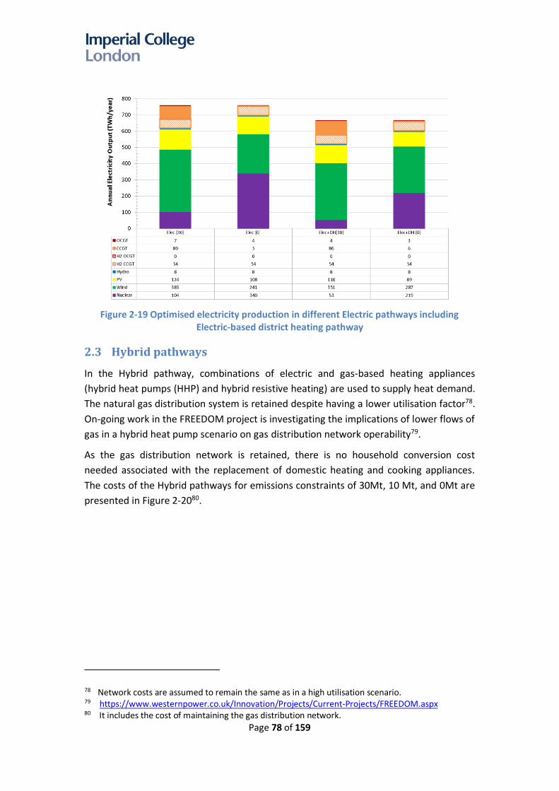
Page 78 of 159
Figure 2-19 Optimised electricity production in different Electric pathways including
Electric-based district heating pathway
2.3 Hybrid pathways
In the Hybrid pathway, combinations of electric and gas-based heating appliances
(hybrid heat pumps (HHP) and hybrid resistive heating) are used to supply heat demand.
The natural gas distribution system is retained despite having a lower utilisation factor78.
On-going work in the FREEDOM project is investigating the implications of lower flows of
gas in a hybrid heat pump scenario on gas distribution network operability79.
As the gas distribution network is retained, there is no household conversion cost
needed associated with the replacement of domestic heating and cooking appliances.
The costs of the Hybrid pathways for emissions constraints of 30Mt, 10 Mt, and 0Mt are
presented in Figure 2-2080.
78 Network costs are assumed to remain the same as in a high utilisation scenario. 79 https://www.westernpower.co.uk/Innovation/Projects/Current-Projects/FREEDOM.aspx 80 It includes the cost of maintaining the gas distribution network.

Page 79 of 159
Figure 2-20 Annual system costs in Hybrid pathways
The system costs in the Hybrid pathways are dominated by the following capex
components: (i) electricity generation, (ii) electricity networks, (iii) heating appliances
including investment in electric (HP,RH) and non-electric (gas) heating, and (iv) hydrogen
infrastructure which is needed to supply hydrogen-based district heating customers. The
operating cost in the electricity system is similar to the Electric pathway. Gas opex cost
(from running the gas boiler element of a hybrid heat pump) is only a small percentage
of overall system costs, as the model suggests its optimal for a heat pump to provide 81-
90% of household heating requirements, with resistive heating and gas boilers providing
the remaining 10-19% (Figure 2-23).
Compared to the costs in a 30Mt case, the system costs in a 0Mt scenario increase by
£6.5bn/year. This is driven by the increase in capex of electricity generation as more
nuclear power is installed (Figure 2-21 ) since the 0Mt case requires larger amount of
firm low-carbon generation (Figure 2-22 ). For example, the proposed nuclear capacity in
Hybrid [30] is 19 GW, while this increases to 45 GW in Hybrid [0]. The increased nuclear
capacity can displace some capacity of wind, PV and other firm capacities such as CCGT
and OCGT.

Page 80 of 159
Figure 2-21 Optimal portfolios of electricity generation in Hybrid pathways
Figure 2-22 Annual electricity production in Hybrid scenarios
Changing from a 30Mt to a 0Mt carbon target would lead to a reduction in gas-related
opex as the gas boilers can only use a limited amount of biogas in the 0Mt cases. This
reduces the utilisation of the gas boilers which increases the utilisation of electric
heating (HP and RH) as demonstrated in Figure 2-23. Heat output from heat pumps in
the model is assumed to be limited to 55°C and so higher temperatures ~65°C (e.g. hot
water), can only be provided by gas boilers or RH.

Page 81 of 159
Figure 2-23 Heat delivered in Hybrid scenarios by different heating technologies
The heat delivered by gas boilers constitutes around 14%, 7%, and 3% of the overall heat
demand in 30Mt, 10Mt and 0Mt case respectively. There is a risk of sub-optimal usage of
gas boilers that may increase the emissions and cost to customers. To prevent sub-
optimal usage of gas and improve energy efficiency, the applications of smart-home
energy optimisation and automation should be explored in addition to the provision of
incentives (or penalties) to customers who can maintain the optimal usage of gas.
Emissions in the hybrid pathway could increase substantially if consumers didn’t use
their hybrid heat pump in a way that is optimal for the overall system (i.e. by using the
gas boiler component more than is considered in the model).
2.3.1 Impact of micro-CHP
An alternative domestic heating source could be a micro-Combined Heat and Power
(CHP) unit supplemented by an auxiliary gas boiler. Micro-CHP has a high-energy
efficiency as it is capable of providing both heat and electricity to consumer premises.
The implications of deploying 10 GW of micro-CHP in the Hybrid pathway with a 30Mt
and a 0 Mt emissions constraint have been investigated, and the results are compared
with the results of the corresponding core Hybrid scenarios.
Given the assumptions related to the cost of micro-CHP (£2500/kW) and the need for an
auxiliary gas / hydrogen boiler, the total cost of the system with micro-CHP is still
marginally higher than the cost of the core Hybrid pathway (Figure 2-24). Furthermore,
the physical size of the current micro-CHP technologies may need to be reduced further

Page 82 of 159
in order for them to be deployed at scale81.
Figure 2-24 Comparing the annual system costs of Hybrid scenarios without and with
micro-CHP
The modelling results demonstrate that small-scale end-use combined heat and power
(micro-CHP) can displace not only the capacity of domestic electric heating appliances
but also the capacity of gas-fired power plants on the system, including hydrogen-based
power generation (Figure 2-25).
Figure 2-25 Impact of micro-CHP on the optimal portfolios of electricity generation in Hybrid pathways
81 Micro-CHP based on steel-cell technology is already appropriate for most domestic premises.

Page 83 of 159
However, the impact of micro-CHP on the low-carbon generation capacity requirement
is marginal. This finding demonstrates that micro-CHP can provide the equivalent of firm
electricity system capacity (assuming it can be controlled to provide capacity during peak
demand) while significantly enhancing generation efficiency, as the heat produced is not
wasted (as in traditional power stations) but used to meet local heat demand. This
reduces annual electricity demand by around 24 TWh. Micro-CHP also displaces the
output of hydrogen-based and traditional CCGT as shown in Figure 2-26.
Figure 2-26 Impact of micro-CHP on the annual electricity production in Hybrid pathways
2.4 Cost performance of core decarbonisation pathways
The system costs of different decarbonisation pathways are presented in Figure 2-27.
Figure 2-27 Annual system cost of core decarbonisation pathways

Page 84 of 159
The key findings of the comparison of different cost components of alternative
decarbonisation pathways are:
1. The costs of alternative decarbonisation pathways are relatively similar for 30Mt,
but the cost differences increase for the H2 pathway in a 0 Mt case
As shown in Table 2-2, the system costs of the decarbonisation pathways for a carbon
emissions target of 30Mt/year are broadly similar; the cost differences between the core
pathways (i.e. Hybrid, Electric and H2) is within 10%, and hence the ranking may change
when different assumptions apply, given the uncertainties around the assumptions in
this analysis.
Table 2-2 Cost performance of different decarbonisation pathways
Pathways Cost (£bn/year)
30Mt 10Mt 0Mt
Hybrid 81.6 84.8 88.0
Elec 87.8 89.5 92.2
H2 89.6 90.2 121.7
The costs marginally increase for a 0Mt/year emissions constraint, except in H2 pathways as
hydrogen production shifts from gas to electricity, which significantly increases the cost of
hydrogen infrastructure (due to a shift from gas-based production to electrolysers).
2. The Hybrid pathway is the least-cost pathway while the cost of the H2 pathway is
found to be the highest cost, compared to the other pathways.
The cost of each of the core pathways is presented in order of merit in Table 2-2. The
Hybrid scenario is identified as the most cost-effective decarbonisation pathway, with
the hydrogen pathway being the most expensive, though it is worth noting that all of
these cost results involve a broad range of uncertainty (see Chapter 3).
There are several key drivers contributing to the cost performance of different
decarbonisation pathways:
- The Hybrid pathway uses highly efficiency hybrid heat pumps to supply the bulk of
heat demand whilst providing the flexibility to use gas during peak demand82
conditions or low renewable output. This flexibility reduces the power system
infrastructure required to meet peak demand (whilst maintaining the security of
supply) compared to the capacity required in the Electric pathway. It is important to
highlight that the model determines the level of capacity needed to maintain the
same level of security in all pathways.
82 In order to test the adequacy of the system capacity to deal with the extreme weather conditions, 1-in-20 years events have been considered in the modelling; three consecutive cold days (the
average daily temperature across GB is -7C) coinciding with low output of renewables. Figure 3-12 shows the profile of ambient temperature used in the studies.

Page 85 of 159
- The Electric pathway requires the highest investment in electricity networks,
particularly at the distribution level, due to a significant increase in peak demand
driven by the electrification of heat. Network costs in the Hybrid pathway are
significantly lower than the costs in the Electric pathway as the use of the gas boiler
component of a hybrid heat pump during peak demand can efficiently reduce the
need for distribution network reinforcement although some network reinforcement
is required to accommodate the growth of distributed renewable generation and
demand response. The H2 pathway tends to require significantly lower electricity
distribution network reinforcements, when compared to the other pathways, except
in the 0Mt case where significant reinforcement is needed to accommodate demand-
side flexibility and integrate more renewable generation into the system, in order to
achieve the carbon target cost-effectively (as it is assumed that all hydrogen is
produced domestically via electrolysis in the 0Mt case, requiring additional low-
carbon electricity generation).
- In the H2 pathway, natural gas is decarbonised through hydrogen production via gas
reforming with CCS83. This reduces the need for investment in low-carbon electricity
generation but requires higher investment in hydrogen and CCS infrastructure.
However, the overall operation and investment cost associated with the hydrogen
system in H2 pathway outweighs the benefits associated with lower investment in
electricity generation. The cost difference becomes much more pronounced in a 0Mt
case as the cost of hydrogen infrastructure increases substantially (as shown in Figure
2-27) due to the shift from ATR to electrolysers (the capex of electrolysers is higher
than the capex of ATR), although the increase in capex can be partially offset by the
reduction in gas opex.
- The H2 pathway is characterised by the lowest energy efficiency due to a number of
energy conversion processes involved: heat pumps are assumed to be between 200%
- 300% efficient or higher84, whereas converting gas to hydrogen for use in domestic
gas boilers is 80% efficient or less (depending on the efficiency of hydrogen boilers85
and efficiency of the hydrogen production86).
- There is a need to replace gas appliances in both the H2 and Electric pathways, which
increases the costs of corresponding scenarios. Hydrogen boilers are significantly
lower cost than heat pumps87, at £75/kWth for a boiler and £600/kWth for a heat
pump but are characterised with higher operating costs. On the other hand, in the
Hybrid pathway there is assumed to be no need to replace other gas appliances,
83 Assuming Auto-thermal Reforming, with 88% HHV efficiency and 96% capture rate, based on Element Energy (2018) Hydrogen Infrastructure: Summary of Technical Evidence
84 Annual average COP of HP used in the study is 2.7. 85 Efficiency of hydrogen boilersis assumed to be 90% 86 Efficiency of ATR is assumed to be 88.5%, based on Element Energy (2018) Hydrogen Infrastructure:
Summary of Technical Evidence 87 More detailed information about household conversion costs can be found in Appendix B.

Page 86 of 159
which minimises the overall household conversion cost.
3. Electric and Hybrid pathways have greater potential to reduce emissions to close
to zero, compared to the H2 pathway.
Comparing the system costs of the core decarbonisation pathways for emissions constraints of 30Mt, 10Mt and 0Mt cases in Table 2-2 demonstrates the following:
- While the cost of meeting 10Mt carbon target in the H2 pathway increases by only
£0.6bn/year compared to the cost in a 30Mt scenario, there is a significant increase in
cost (more than £30bn/year) in H2 pathways when the carbon target changes from
30Mt to 0Mt, driven by a change in hydrogen production from ATR to electrolysers.
The system costs of electrolysers are higher than ATR plants as the application of
electrolysers also requires a significant increase in investment in low-carbon
electricity generation. Improved carbon capture rates on gas reforming plant or
importing low-carbon hydrogen to the UK could allow for reduced emissions in the
H2 pathways.
- The costs of the Electric and Hybrid pathways in 0Mt cases are also 4 - 6 £bn/year
higher than the corresponding costs in 30Mt; this is driven by the increase in
electricity generation capex as a higher capacity of nuclear is required to provide a
firm (non-variable) source of low-carbon electricity. An increase in nuclear capacity is
also observed in an H2 0Mt case.
- Achieving zero emissions with a hybrid pathway will depend on the availability of low-
carbon biogas, as well as consumer usage of hybrid heat pumps.
The analysis demonstrates that:
- Systems with more stringent carbon emission targets will lead to higher costs;
- Further decarbonisation beyond 30 Mt is possible at a limited additional cost in the
hybrid and Electric pathways, this is also true for deep decarbonisation towards a
zero-emissions energy system (costs are 6-7% higher in a 0 Mt case).
- Electric and Hybrid pathways provide more optionality towards a zero-carbon future
compared to the H2 pathway, which is limited up to 10 Mt unless there is an
improvement in the capture rate of CCS.
4. The costs of low-carbon systems are dominated by capital expenditure (capex)
while operating expenditure (opex) is significantly lower.
In the 30Mt cases, system operating costs are a relatively small component of overall
system costs, i.e. less than 25% in the H2 pathway, 5% in Electric, and 6% in Hybrid.
Towards zero carbon, the opex component in all decarbonisation pathways reduces
significantly as most of the energy is produced by zero marginal cost renewable
resources and low operating cost nuclear generation, while the use of gas is limited to

Page 87 of 159
only low-carbon gas (biogas, bioenergy)88, with any hydrogen being produced by
electrolysis supplied by low-carbon electricity generation. This implies that the system
costs will be very sensitive to cost of financing the infrastructure89 in the scenarios and
much less sensitive to future fluctuations in gas prices.
2.5 Impact of heat decarbonisation strategies on the electricity
generation portfolio
Different decarbonisation pathways require substantially different electricity generation
portfolios, as the choice of heating pathway will have significant implications on gas and
electricity systems. The coordination of the design and operation of gas, heat and
electricity systems is important for minimising the whole-system costs of
decarbonisation. Optimised generation portfolios for the core decarbonisation scenarios
are presented in Figure 2-28.
Figure 2-28 Optimal generation portfolio in different decarbonisation pathways
A number of conclusions can be derived from the optimal generation portfolio proposed
by the model:
88 The CCC specified that 135 TWh of primary bioenergy should be used to provide ‘negative emissions’ via Bioenergy plant with Carbon Capture and Storage (BECCS), though these negative emissions are not considered within the carbon constraint in the model as they are accounted for across the economy. The model chose to use BECCS to produce hydrogen in all cases, with the hydrogen being used in either hydrogen-based power plant or gas boilers. The cost of BECCS plant is included in all pathways. BECCs were assumed to be zero cost in this analysis. Cost of biogas was assumed to be the same as the cost of natural gas.
89 Financing costs assumed in the study are between 3.5% and 11% depending on the technologies.

Page 88 of 159
1. Maximum capacity of low-carbon generation that is assumed to be available by
2050 is sufficient to reach the zero-carbon target90.
Across all scenarios a significant capacity of low carbon electricity generation is required,
representing an increase of 130-450% of electricity generation capacity on today’s levels
(of around 100 GW). The optimal generation portfolio also includes hydrogen based
CCGT and OCGT plant. There is only one case, i.e. 0Mt H2 pathway, where the capacity
of PV, wind and nuclear hit the upper limits of UK deployment potential by 205091
assumed in the modelling. This increase in electricity generation capacity implies
significant build rates (around new 5-9 GW/year of low-carbon generation technology)
between now and 2050, in order to meet the decarbonisation targets. Any constraints
on build rates, such as financing, materials or skills issues could reduce the achievable
level of energy system decarbonisation by 2050.
2. Energy system flexibility and interactions across different energy systems
significantly influence the power generation portfolio.
The whole-system cost of the scenarios depends on the level of flexibility which can be
provided across (and including the interaction between) the heat and electricity sectors,
which will impact the deployment rates of low carbon generation technologies, with the
aim of meeting the carbon target at minimum costs. The modelling results demonstrate
that improving system flexibility can reduce the annual system cost by up to £16.2
bn/year92 in an Electric 0Mt pathway (£4bn/year in a hydrogen 0 Mt pathway). The
flexibility provided by demand-side management or energy storage across different
energy vectors (electricity, gas, heat) can improve the utilisation of low-carbon
generation and reduce the overall requirement of production capacity and network
infrastructure reinforcement93. For example, if heat demand is supplied by electric
heating, reducing the peak of heat demand by preheating94 or using thermal storage can
reduce the required firm generation capacity (by up to 110 GW)95. The studies
90 Maximum potential capacities of wind, PV, CCS and nuclear provided by the CCC were 120 GW, 150 GW, 45 GW and 45 GW respectively, based on build rate constraints of 4 GW/year for wind technologies, 1.5 GW/year for nuclear/CCS, 5 GW/year for solar, 3 GW/year for ATRs, 3 GW/year for electrolysers, with technologies assumed to be deployed between 2030 and 2050
91 Due to insufficient capacity of low-carbon electricity generation, this case cannot meet the zero-carbon target and the annual carbon emissions were 2 Mt/year.
92 The max system cost difference between the system with full and no flexibility across pathways 93 In a system where no flexibility can be provided at the domestic level, network costs are £5
bn/year higher. 94 Preheating involves heating the households earlier than it would be otherwise done while utilising
inherent heat storage in the fabric of the houses. This type of flexibility is critical for reducing system peaks, enhancing the value of the provision of balancing services and increasing utilisation of renewables by electric heating, which significantly reduces the cost of decarbonisation.
95 In the Electric 0 Mt scenario, the use of preheating can reduce more than 40 GW of firm generating capacity.
Page 89 of 159
demonstrate that most of the value of system flexibility (including preheating) comes
from reducing spend on low-carbon electricity generation (Figure 2-27).
3. A significant capacity of firm low-carbon generation is needed in all pathways with
0Mt carbon target
• Analysis demonstrated that meeting a strict zero-emission target cost-effectively
would require a significant capacity of nuclear generation in all pathways, due to the
variability of renewable production and the need to eliminate emissions associated
with management of demand-supply balance. Hence, in the 0 Mt case, a significant
amount of capacity of variable renewables is replaced by firm low-carbon generation
capacity, i.e. nuclear. The results demonstrate that although in the short and medium
term the focus can be on deployment of variable RES, in the long-term, to achieve a
zero-carbon emissions target, firm low-carbon generation technologies such as
nuclear (or alternatives) will be required, e.g. for the 0Mt, in all core pathways, more
than 40 GW of nuclear generation is deployed. The appropriate portfolio of power
sector technologies, therefore, depends on the desired level of decarbonisation of
the energy system.
• Further research related to the provision of system inertia is needed to investigate
the impact on the optimal portfolio of generation technologies, particularly in 0 Mt
case, as the provision of synthetic inertia (e.g. by wind generation) could reduce the
volume of nuclear and increase capacity of renewables, while on the other hand,
coordinated de-loading of nuclear generation during low demand and high renewable
output conditions would reduce the size of the largest loss and hence enhance the
value of nuclear generation.
4. Pre-combustion CCS generating plant is more attractive than post-combustion CCS.
No post-combustion CCS plant is selected due to presence of residual carbon emissions
and higher cost of CCS technology (it is important to note that post-combustion fossil
CCS cannot be used in a 0Mt scenario due to residual carbon emissions). There is,
however, a significant volume of pre-combustion CCS, i.e. hydrogen-based combined
cycle gas turbine and hydrogen-based open cycle gas turbine primarily in the Electric and
Hybrid scenarios. Pre-combustion-hydrogen-based generation can be considered as
complementary to CCS generation as it enables decarbonisation of traditional gas plant
technologies and can provide flexibility while making efficient use of the hydrogen
infrastructure.
5. The installed capacity of electricity generation in the Electric pathways is
significantly larger than in other pathways.
Full electrification of heating demand in the Electric pathway will substantially increase
peak electricity demand. Hence the corresponding amount of firm-generation capacity
in the Electric pathway is about 100 GW larger compared to other pathways. It should be
noted that in the Electric pathway there is a significant amount of peaking plant (OCGTs)

Page 90 of 159
that are supplied by biogas and operate at very low load factors (operating during high
peak demand conditions driven by extremely low external temperatures). In the Hybrid
pathway, on the other hand, the extreme peak of heat demand is directly supplied by
gas boilers using biogas in the gas grid rather than electricity, and hence the capacity
requirement for peaking plant is much lower.
Considering the uncertainty across different heat decarbonisation pathways and
emissions targets, “no regret”96 capacity of specific low-carbon generation technologies
can be determined by taking the minimum of the proposed capacity for the
corresponding generation technology across different pathways (given the costs of
different low carbon generation technologies) and across emissions targets. This
suggests that a capacity of at least 74 GW of wind generation is useful in all scenarios,
given the seasonal profile of both wind generation and energy demand97. The modelling
also indicates a role for at least 5 GW of nuclear power, and 3 GW of hydrogen-fuelled
CCGT capacity, across all pathways.
It is important to highlight that more electricity generation capacity will need to be built,
but the optimal generation portfolio will depend on both the decarbonisation pathway
and the carbon target. A higher capacify of firm low-carbon generation is needed in a
system with a very-low emissions target. For example, in the Elec 30Mt case, there is a
need for 13 GW of nuclear, 117 GW of wind, 146 GW of PV and 12 GW of H2 CCGT while
in the H2 30 Mt case, the requirements are 5 GW of nuclear, 77 GW of wind, 63 GW of
PV, 12 GW of H2 CCGT. However, in the H2 0 Mt case, the required capacity for nuclear,
wind, PV and H2 CCGT are 45 GW, 120 GW, 150 GW, and 3 GW. There is a significant
increase in the capacity of nuclear, wind and PV alongside a reduction in H2 CCGT. In this
case, hydrogen is mainly produced from low-carbon generation sources (as the
emissions from gas-based hydrogen production are too high in this case) and used for
heating instead of for electricity production. In this case significant amount of short and
long term flexibility services is provided electrolysers. Sufficient firm power generation
capacity is also needed to ensure that peak demand is met when renewable generation
production is low.
It is important to note that the optimal generation mix is system specific and depends on
the assumptions taken in the model. Therefore, the low/no regret capacities identified
by the model provide a tangible indicator of the minimum capacity needed for each low-
carbon generation technology across different scenarios.
96 Low/no regrets capacity is defined as the capacity that will be needed irrespective of the decarbonisation pathway adopted in the future.
97 The results are based on the assumptions and system conditions used in the studies, e.g. it was assumed that the system was supported by flexibility from demand response, energy storage, generators, and interconnectors.

Page 91 of 159
2.6 Alternative heat decarbonisation strategies
2.6.1 District heating and micro-CHP
Successful implementation of district heating in Denmark (and other EU countries) and
the potential application of end-use micro-CHP technologies have raised questions
about the contribution these technologies could make to heat decarbonisation
pathways. The results are compared with the results of the core scenarios in the
corresponding pathways. The costs and system implications of implementing these
alternative strategies can be observed in Figure 2-29.
Figure 2-29 Annual system costs of alternative heat decarbonisation pathways through
district heating and micro-CHP compared with the costs of core scenarios
The key findings from the study are:
1. National district heating pathways are significantly more costly than other heat
pathways due to the expenditure associated with the deployment of heat
networks.
The analysis demonstrates that national deployment of district heating incurs a higher
cost than systems with domestic level heating appliances, which is primarily driven by
the cost of deploying heat networks and the cost of connecting consumers to heat
networks, including new assets needed to control heat and metering in dwellings. On
the other hand, due to economies of scale, the cost of heating devices in district heating
networks is significantly lower (35%-50%) than the cost of domestic heating appliances.
In the Electric pathway, there is also a significant reduction in the capital cost of the
electricity generation driven by a higher COP of industrial heat pumps (4 on average)
Hydrogen pathways
Electric pathways
Hybrid pathways

Page 92 of 159
compared to the COP of domestic heat pumps (less than 3 on average). However, this
cost reduction is still outweighed by the increase in costs associated with heat network
deployment and connection.
While the study provides evidence that national deployment of district heating will not
be cost-effective, local applications of district heating in high-heat-density areas could
provide a more cost-effective solution. Heat demand in urban areas makes up around
40% of the total heat demand, whilst the cost of urban heat networks is less than 25%98
of the cost of heat networks in non-urban areas.
2. Micro-CHP, installed in households, could contribute to reducing the capacity of
centralised electricity generation and network reinforcement.
Small-scale end-use combined heat and power (micro-CHP) can substitute for / contribute to
the capacity of electric heating appliances, reduce distribution network costs and displace
the capacity of gas-fired plants including hydrogen power generation, while the impact on
RES and the nuclear capacity requirement is marginal. This finding demonstrates that micro-
CHP could provide firm capacity (assuming it is able to be managed to provide capacity
during peak demand) whilst significantly enhancing generation efficiency, as the heat
produced from thermal electricity generation is not wasted but is used to meet local heat
demand. However, given the assumptions related to the cost of micro-CHP (£2500/kW) and
the need for an auxiliary gas / hydrogen boiler, the total cost of the system with micro-CHP is
still marginally higher than the cost of the core Hybrid pathway (but slightly lower than the
Electric scenario). Furthermore, a reduction in the physical size of the traditional micro-CHP
technologies may also need to be achieved in order for them to be deployed at scale99.
2.6.2 Regional scenarios
Regional approaches to deploying hydrogen, such as in a group of regions where gas
terminals are available or in urban areas with high energy demand density have also
been investigated and analysed for the 30Mt and 0Mt carbon emission cases. Three
regional scenarios are considered: (i) Hybrid – H2 North assumes that the main heating
system in the North of GB (Scotland, North of England, North Wales) is fuelled by
hydrogen while the other regions use hybrid heat pumps; (ii) Hybrid – H2 Urban assumes
that hydrogen heating systems are deployed in all urban areas while other regions use
hybrid heat pumps for heating; (iii) Hybrid – Urban DH HP assumes the use of electric-
based district heating with highly-efficient ground-source heat pumps100. The results are
presented in Figure 2-30, and the annual system costs of the regional scenarios are
compared against the costs of non-regional Hybrid systems (the first two bars in the
graph).
98 The total length of urban networks is less than 25% of the overall length of distribution networks. 99 Micro-CHP units based on steel-cell technology is already appropriate for most domestic premises. 100 Annual average COP is 4.

Page 93 of 159
Figure 2-30 Costs of alternative Hybrid pathways
Use of hydrogen in Hybrid regional scenarios can reduce the demand for low-carbon
generation capacity at the expense of increased hydrogen infrastructure operating costs.
The results demonstrate that for the 30Mt case, deployment of hydrogen in the
Northern region could be an attractive alternative to the non-regional scenario as the
costs are marginally lower by £0.8bn/year. This implies that for some regions, hydrogen
conversion can be a cost-effective heat decarbonisation option. This favours regions in
close proximity to existing gas terminals, and carbon storage areas, reducing overall
networks costs. Towards a zero-carbon energy system, the cost of Hybrid- H2 North [0]
is £6.6bn/year higher than the cost of Hybrid [0] due to the need to use electrolysers
and low-carbon generation technologies to produce hydrogen. The costs of regional
Hybrid – H2 Urban cases, both for 30Mt and 0Mt cases, are higher than a non-regional
Hybrid system by 3.9 – 13.4 £bn/year. The cost of producing hydrogen in proximity to
urban areas is assumed to be 50% higher than the cost of producing hydrogen by large-
scale plants located near gas terminals; this increases the capex of hydrogen
infrastructure in the Hybrid – H2 Urban scenarios.
One of the main barriers to district heating is the high cost of deploying heat networks.
Therefore, the implementation of district heating may be constrained to the high-heat-
density areas, e.g. urban areas. Heat demand in high-density areas makes up around
40% of the total heat demand (Table F-1 in Appendix F), whilst the corresponding cost of
heat networks is less than 25% of the cost of heat networks in low-heat density areas101.
The results of the Hybrid – Urban DH HP scenario demonstrate that the efficiency of
101 The total length of urban networks is less than 25% of the overall length of distribution networks.

Page 94 of 159
industrial heat pumps can reduce the infrastructure costs of electricity generation
compared to the corresponding costs in a Hybrid scenario, though the cost of deploying
district heating infrastructure outweighs these benefits. Overall, the total costs of the
Hybrid – Urban DH HP scenario are 2.8 – 4.2 £bn/year higher than the costs of the
Hybrid pathways.
These results demonstrate the importance of considering regional diversity in national
level heat decarbonisation decisions, though the cost optimality of this diversity depends
on the desired level of decarbonisation. Converting heat to hydrogen in some regions
could be a cost-effective decision as part of a hybrid national level heat decarbonisation
strategy.

Page 95 of 159
Chapter 3. Sensitivity studies on
the decarbonization
pathways
3.1 Key sensitivity factors
A range of studies has been carried out to understand the impact of different
assumptions on the core decarbonisation pathways. The sensitivity studies focus on two
carbon targets (30Mt and 0Mt) and are listed and summarised in Table 3-1.
Table 3-1 List of sensitivity studies
Sensitivity Low Central High
H2 technologies - ATR SMR
H2 import - No hydrogen Import
There is no constraint on how much hydrogen can
be imported at £25/MWh.
Discount rate / cost of finance
3.5% cost of capital for all investments
3.5% cost of capital for heating appliances
Networks: 5.7% Generating plants:
5.8%-11%
7.5% cost of capital for heating appliances
CAPEX of low-carbon electricity generation
Wind: £40/MWh PV: £30/MWh
Nuclear: £50/MWh
Wind: £50/MWh PV: £40/MWh
Nuclear: £70/MWh
-
Carbon emissions target 0 Mt/year 30 Mt/year -
Space heating demand (domestic)
224 WTh 283 TWh 341 TWh
Flexibility102 No demand-side response and no energy storage
50% availability of potential demand-side response and
energy storage
High availability and low cost of demand-side response and energy
storage
End-use heat appliance cost
H2 boiler: £100/kWth NG boiler: £100/kWth
HP: £400/kWth RH: £100/kWth
H2 boiler: £150/kWth NG boiler: £125/kWth
HP: £600/kWth
H2 boiler: £250/kWth NG boiler: £125/kWth
HP: £800/kWth RH: £200/kWth
102 System flexibility from flexible electricity demand (industrial and commercial load, smart charging of EV, smart appliances, electricity and heat storage, and preheating measures). No cost is attributed to demand flexibility, but the costs of energy storage are included

Page 96 of 159
Sensitivity Low Central High
RH: £150/kWth
Fuel prices (gas)103 39 p/therm 67 p/therm 83 p/therm
Heat peak demand (domestic space
heating)
173 GWth (10% reduction from the central case)
192 GWth104 -
The sensitivity studies are carried out for the 30Mt and 0Mt cases.
3.2 Hydrogen Scenario
Figure 3-1 shows the results of the sensitivity studies on the H2 decarbonisation
pathways with a 30Mt carbon target.
Figure 3-1 Cost sensitivity of H2 decarbonisation pathways [30Mt]
The results demonstrate the following: (from the most sensitive factor towards the less
sensitive)
- The cost of H2 decarbonisation pathways is very sensitive to the specified emissions
target. To achieve zero emissions, there is a need to use electrolysers to produce
hydrogen. The cost of hydrogen production via electrolysis is larger as it requires
substantial investment in electrolysis as well as investment in low-carbon electricity
generation technologies. Having a stricter carbon target, from 30 Mt to 0 Mt per year,
103 BEIS ,”Updated Energy & Emissions Projections: Annex M,” 2017 104 Based on the original heat demand (excluding the impact of preheating and thermal storage plants)

Page 97 of 159
increases the system costs by £32.1bn/year105.
- Assuming that hydrogen can be imported at low cost (£25/MWh) will lower the
system cost of H2 decarbonisation pathway by £14.6bn/year from reducing the
investment needed in GB hydrogen production technologies (which is costlier).
Additional network and storage will still be needed to enable hydrogen transmission
to the demand centres across GB. Importing hydrogen also reduces domestic carbon
emissions associated with gas-based hydrogen production, and therefore, less low-
carbon electricity generation capacity will be needed for the same emissions target.
- As capital costs dominate the overall system cost, the impact of changes in financing
costs will be substantial. The “Low” scenario reduces the cost by £16.2bn/year while
the “High” scenario increases the total cost by £2.9bn/year.
- For the H2 30Mt scenario, the system cost is also sensitive to fuel prices as hydrogen
production is based on gas consumption. It is also interesting to note that the impact
of low and high gas prices is asymmetrical due to two main reasons: (i) the gas price
range used is asymmetrical; (ii) the optimal investment and operation of the system
proposed by the model changes following the changes in gas prices. The low gas price
scenario reduces the system cost by £9.7bn/year while the high gas price scenario
increases the cost by £4.3bn/year. If the gas price is low, it will reduce gas opex and
more hydrogen could be allocated for electricity production via hydrogen-fuelled
power generation; this reduces the required investment in other low-carbon
electricity generation plants. If the gas price is high, it will mainly increase gas opex as
the use of hydrogen in power production in the Central scenario is less than 4%.
- Having lower capex for low-carbon generation technologies will reduce the system
cost by £4.9bn/year. The lower capex could be achieved, e.g. by technological
enhancement, improving energy conversion efficiency, and cutting production and
installation costs.
- Using SMR instead of ATR to produce hydrogen increases the cost by £7.2bn/year
(see the discussion in section 2.1.1.1).
- The cost of heating appliances also affects the overall cost. Lower cost of hydrogen
boilers will reduce the cost by £1.5bn/year; on the other hand, a higher cost of
hydrogen boilers will increase the overall cost by £6.9bn/year.
- The reduction in space heating demand reduces overall hydrogen production, leading
to lower system costs by £0.9bn/year. On the contrary, a higher heating demand will
increase hydrogen demand leading to higher system cost – by £6.1bn/year- as more
hydrogen needs to be produced. This highlights the benefits that increased energy
efficiency could deliver.
- For the H2 30Mt case, the cost of reducing additional system flexibility is
105 As described in Section 2.1, the increase in system costs is £29bn/year when the carbon emissions reduce from 10Mt to 0Mt.

Page 98 of 159
£2.8bn/year, while improving the system flexibility can save additional £1.1bn/year.
- Given the presence of flexibility that can smooth energy demand profiles (both
electricity and heat), the further reduction in peak heat demand (10%) does not lead
to significant cost reductions.
- It is important to note that the production and use of hydrogen is optimised in
relation to operation and investment requirements of the electricity system and
hence and this is not presented as the flexibility service, and hence the benefits of
additional flexibility sources as defined in the study are relatively modest.
The studies were extended to the 0Mt cases, and the results are presented in Figure 3-2.
The trends are the same, but the sensitivities are intensified as the carbon emissions
target is set to 0Mt. For example, assuming full imports of hydrogen reduces costs by
£14.6bn in the 30Mt case and £46.5bn in the 0Mt case. These results emphasize the
importance of lowering the cost of hydrogen production technologies, especially for a
zero-carbon emissions scenario. Similarly, the impact of discount rates is more
significant, as a larger capital investment in low-carbon electricity generation is needed
in the 0Mt case. In contrast, the sensitivity related to the fuel prices is lower in the 0Mt
case as the use of gas is significantly reduced in the 0Mt scenario. The model optimises
the operation of electrolysers and hydrogen storage in line with requirements of both
the electricity and gas systems. This cross-vector optimisation provides significant
flexibility to the electricity system, and hence the benefits of other sources of flexibility
presented in these figures are not very significant.
Figure 3-2 Cost sensitivity of H2 decarbonisation pathways [0Mt]

Page 99 of 159
3.3 Electricity Scenario
Figure 3-3 shows the results of the sensitivity studies on the Electric decarbonisation
pathways with a 30Mt carbon target. The results indicate that:
- Overall system costs are highly sensitive towards financing costs. This is expected
since the majority of the costs, particularly in the Electric pathway, are dominated by
capital costs. Thus, reducing the cost of capital for these investments will have a
major impact. For the same reason, lower capex of low-carbon generation also leads
to lower system costs.
- Having a stricter carbon target will increase system costs by £4.4bn/year.
- Flexibility is important for the Electric pathway. Having low flexibility costs more than
£6bn/year while having more flexibility can save additional £3.5bn/year (up to
£16bn/year in the 0 Mt pathway). It is important to note that the model optimises
the use of hydrogen (produced mostly from BECCS) to support the electricity system,
and this cross-vector optimisation delivers very significant flexibility. However, the
benefits of flexibility presented in figure below refer only to the value of additional
flexibility sources (e.g. pre-heating, smart charging of EVs etc.).
- The costs are also sensitive towards space heating demand; a low heat demand
scenario reduces the costs by £6.3bn/year while in the high heat demand scenario
the costs increase by £4.6bn/year.
- The high cost of electric heating appliances will increase overall costs by £1.3bn/year
while low appliance costs will reduce costs by £4.3bn/year.
- Gas price variations have little impact on overall system costs as the utilisation of gas-
fired power generation (CCGT and OCGT) is only about 12% of total annual electricity
production.
- The impact of reduced peak heat demand is modest as the system already has a
certain amount of flexibility which limits any further benefits of reducing peak
demand. Load shifting and energy storage in the system have been used to flatten
the daily energy demand profile (see Chapter 4 for more detail on this), and
therefore, the 10% reduction of heat peak demand becomes less relevant.

Page 100 of 159
Figure 3-3 Cost sensitivity of Electric decarbonisation pathways [30Mt]
The studies are extended to the 0Mt cases, and the results are presented in Figure 3-4.
Figure 3-4 Cost sensitivity of Electric decarbonisation pathways [0Mt]
The trends are similar to the ones observed in the 30Mt cases, but the sensitivities are
intensified as the carbon emissions target is set to 0Mt. For example, having a lower cost
of finance can reduce the cost by around £20bn/year, this value is higher compared to
the savings (£17.7bn/year) obtained in the 30Mt case. Similarly, the benefit of having
flexibility is also higher in the 0Mt case (£14.2bn/year) compared to the benefit in the
Page 101 of 159
30Mt case (£6.4bn). On the other hand, the sensitivity related to changes in fuel prices
becomes much lower, as the use of gas is only limited to carbon-neutral gas in the 0Mt
case.
3.4 Hybrid Scenario
Figure 3-5 shows the results of the sensitivity studies on the Hybrid decarbonisation
pathways with a 30Mt carbon target. The results indicate the following:
- The system cost of the Hybrid system is also dominated by capital cost, and
therefore, the impact of low or high financing costs is high. The low discount rate
scenario leads to savings of £15.6bn/year, and the high discount rate leads to higher
costs of £4.7bn/year. For the same reason, lowering the capex of low-carbon
generation would also lead to a £8.3bn/year reduction in costs compared to the base
case.
- Setting a stricter carbon target (i.e. 0Mt) increases annual system costs by
£6.5bn/year as more investment in low-carbon generation technologies will be
needed.
- The cost increases by £4.2bn/year if the appliance costs are high; the cost decreases
by £1.2bn/year in the case of low appliance costs.
- Having lower or higher heat demand will reduce or increase annual system cost by
around £3.6bn/year.
- Flexibility is also important in the Hybrid system as it can save £3.1bn/year; improving
flexibility can deliver additional savings of £1.4bn/year. It is important to note that
use of gas and electricity for heating is inherently optimised by the model, and this is
not considered explicitly as a flexibility service. The benefits of flexibility quantified in
the study refer to additional flexibility sources, such as pre-heating, smart-charging of
EVs, etc.
- Having lower or higher gas prices also leads to lower or higher system costs as gas is
still used for both power generation and heating in the Hybrid system.
- Reducing peak heat demand by 10% has a modest impact on system costs as the
system already has some flexibility which limits the benefit of reducing peak heat
demand as the daily heat demand profile is flattened.

Page 102 of 159
Figure 3-5 Cost sensitivity of Hybrid decarbonisation pathways [30Mt]
Sensitivity studies related to the 0Mt scenario were carried out, and the results are
presented in Figure 3-6. The trends are similar, but – as in other pathways - the
significance of the sensitivities tends to increase as the carbon emissions target becomes
more stringent. For example, lowering financing costs can reduce costs by around
£18.9bn/year, this value is higher compared to the savings (£15.6bn/year) obtained in
the 30Mt case. Similarly, the benefit of flexibility is also higher in the 0Mt case
(£7.8bn/year) compared to the benefit in the 30Mt case (£3.1bn/year). On the other
hand, the significance of changes in fuel prices is reduced as the use of gas is reduced in
the 0Mt case.
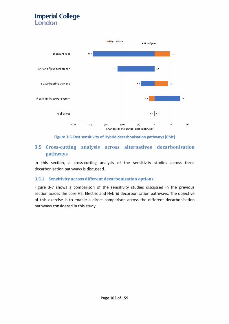
Page 103 of 159
Figure 3-6 Cost sensitivity of Hybrid decarbonisation pathways [0Mt]
3.5 Cross-cutting analysis across alternatives decarbonisation
pathways
In this section, a cross-cutting analysis of the sensitivity studies across three
decarbonisation pathways is discussed.
3.5.1 Sensitivity across different decarbonisation options
Figure 3-7 shows a comparison of the sensitivity studies discussed in the previous
section across the core H2, Electric and Hybrid decarbonisation pathways. The objective
of this exercise is to enable a direct comparison across the different decarbonisation
pathways considered in this study.

Page 104 of 159
Figure 3-7 Comparison between the cost sensitivity of different decarbonisation pathways
[30Mt]
The results of the sensitivity studies presented in Figure 3-7 demonstrate the following:
- For all pathways, low financing costs would be the primary driver for reducing the
system cost as the low-carbon energy system costs are driven by the capital rather
than operating costs.
- The most significant cost increase in the H2 scenario is primarily driven by the need
to change the hydrogen production from gas to low-carbon power generation
technologies.
- The 2nd most substantial cost reduction for the H2 scenario is found in a case when
low-cost hydrogen imports are available (risks associated with significant energy
imports are not within the scope of this study). By importing hydrogen, the
infrastructure needed to transport, and store hydrogen can be reduced (assuming
that imports can be delivered at all times, and to the right locations). Consistently low
gas prices could also improve the viability of a hydrogen pathway, compared to other
pathways.
- For the same reason, a reduction in the cost of low-carbon electricity generation
reduces the overall cost significantly.
- In all pathways, meeting a stricter carbon target will increase system costs. While the
increase in costs in the Electric and Hybrid pathways is between 4.4 and 6.5 £bn/year,
the increase in costs in the H2 pathway is much more substantial (more than
£30bn/year); this implies that H2 would be the highest cost pathway towards a strict
zero carbon emissions target.

Page 105 of 159
- The reduction in annual heating demands, driven by improved energy efficiency
reduces total system costs by 0.9 – 6.3 £bn/year. Across the three pathways, the
highest impact of heat demand reduction is in the Electric pathway.
- The benefits of additional flexibility are largest in the Electric scenario and lowest in
the H2 pathway, as both H2 and Hybrid scenario involve more cross-vector flexibility,
which reduces the benefits of other sources flexibility as defined in the study.
- The cost of an H2 pathway is more sensitive towards fuel prices compared to the
Electric and Hybrid pathway as the volume of gas used in the last two pathways is
much lower compared to the H2 pathway since heat demand is met primarily by
electric heating (HP) and most of the energy comes from low-carbon resources.
- The impact of a reduction in peak heat demand is relatively marginal in all pathways,
as a significant level of system flexibility is assumed to be delivered at a household
level via pre-heating and thermal storage. Without this flexibility, the impact on costs
of peak heat demand would be much more significant.
Furthermore, sensitivities across different decarbonisation pathways for the 0Mt cases
are presented in Figure 3-8.
Figure 3-8 Comparison between the cost sensitivity of different decarbonisation pathways
[0Mt]
As the impact of different assumptions may get intensified in zero-carbon scenarios, the
importance of different parameters on the costs of different decarbonisation pathways
may also change. In most cases, the trends are the same as ones observed in the 30Mt
cases with some exceptions such as:
- The impact of the reduced cost of finance in the H2 pathway is higher than in the
other pathways, as in a 0 Mt scenario domestic hydrogen is produced by

Page 106 of 159
electrolysers, requiring an increase in low-carbon electricity generation. This is driven
by a need for much larger investment in low-carbon generation technologies
compared to the other pathways in a 0Mt H2 case. This is in contrast to the results
associated with the 30Mt scenarios where the highest impact of reducing the
discount rate is found in the Electric pathway.
- For the same reason, the impact of reducing capex of low-carbon electricity
generation technologies is highest for the H2 0Mt case. This is in contrast to the
results of the 30Mt case, where the largest impact is found in the Hybrid pathway.
3.5.2 Cost of decarbonisation across different scenarios
The cost range of the core decarbonisation pathways across the sensitivity studies is
compared in order to identify the drivers and conditions in which one particular pathway
may become significantly more or less cost competitive compared to other pathways.
The results are presented for the 30Mt (Figure 3-9) and 0Mt (Figure 3-10) cases.
The results for the 30Mt cases indicate the following:
- Across the uncertainties listed above the core Hybrid system (£81.6bn/year) remains
the least-cost solution, followed by the Electric pathway (£87.8bn/year) and H2
pathway (£89.6bn/year). It can, therefore, be concluded that the Hybrid pathway is
the most robust decarbonisation pathway to reach a 30Mt carbon target.
- There are a few conditions where an H2 pathway becomes more competitive, i.e. if
large-scale low-cost imports of hydrogen are available (at £25/MWh), and all other
conditions remain the same, or if gas prices are low (39p/therm).
Figure 3-9 Comparison between the cost range of different decarbonisation pathways
[30Mt]

Page 107 of 159
- The cost of the Electric pathway is always higher than the cost of a Hybrid pathway,
indicating the importance of cross-vector flexibility. The cost of the Electric pathway
is close to the cost of the Hybrid pathway particularly when heating demand is low.
For the 0Mt cases, the results are presented in Figure 3-10.
Figure 3-10 Comparison between the cost range of different decarbonisation pathways
[0Mt]
The results demonstrate the following:
- The cost of the core Hybrid pathway is the lowest (£88.0bn/year) compared with
Electric pathway (£92.2bn/year) and H2 pathway (£121.7bn/year). The cost of the H2
pathway is the highest in most cases, with the exception of hydrogen import at low
cost.
- The cost difference between the Hybrid/Electric and H2 pathway increases compared
to the cost difference between the corresponding pathways in the 30Mt cases. In
contrast, the cost differences between the Electric and Hybrid decreases in the 0Mt
cases. This is expected since the Hybrid system becomes more dependent on
electrification to decarbonise the heating and gas systems, as less residual emissions
are allowed for in the gas boiler element of the hybrid heat pump.
Since the Hybrid pathway is the least-cost scenario in both the 30Mt and 0Mt cases, it
can be concluded that the Hybrid scenario is the most robust decarbonisation pathway,
although the absolute level of decarbonisation that can be achieved through this

Page 108 of 159
pathway depends on the availability of biogas, and consumer usage of the heat pump
and boiler elements of the hybrid heat pump106.
3.6 Impact of improved energy efficiency and changes in heat
demand
The optimal choice of decarbonising heat may depend on the level of heat demand in
the future which could be influenced by many factors including improved housing
insulation and temperature increases due to climate change. In this context, the system
costs of the core scenario are compared with the costs of two lower heat demand
scenarios107. The three scenarios in Figure 3-11 are (i) core scenario, (ii) low demand
scenario, and (iii) low demand with climate change adjustment. The corresponding
annual domestic heat demands (including both space-heating and water-heating
demand) used in these three scenarios is (i) 349 TWhth, (ii) 290 TWhth, and (iii) 234
TWhth. The last scenario assumes a 2C increase in UK average annual temperature in
2050.108 The studies were carried out for all three main pathways for the 0Mt cases.
Figure 3-11 Impact of reduced heat demand on the system annual costs
Figure 3-12 shows the daily variation of outdoor temperature used in the study for both
the base cases and the cases with increased average temperature due to climate change
effect (the annual average of the increased temperature is around 2C). Based on the
temperature profiles in Figure 3-12, the COP of heat pumps is then derived from BEIS’s
106 Annual use of the boiler component is around 14% in the 30 Mt scenario and 3% in the 0 Mt scenario
107 The background of these scenarios is described in Appendix C. 108 The core scenarios use historical temperature data with a few consecutive days of modified
demand to simulate extreme weather events, i.e. very cold days with low output of renewable energy.

Page 109 of 159
2016 report on heat pumps109. Figure 3-13 shows the COP of heat pumps used in the
study.
Figure 3-12 Impact of climate change on the ambient temperature
Figure 3-13 Impact of climate change on the COP of HP/HHP
The results demonstrate that annual system costs are lower when domestic heating
demand is reduced, though it is worth noting that the results exclude the costs
associated with reducing this demand (e.g. investment cost for improving thermal
insulation and using the smart-energy system). In addition to demand reductions the
109 BEIS, “Evidence Gathering – Low Carbon Heating Technologies,” November 2016. The COP data
are based on the use of air-source HP and water output temperature of 55C.

Page 110 of 159
results for the “Low demand with CCA” are influenced by the assumed higher annual
average temperature in this pathway, resulting in a higher average COP for heat pumps
in the Electric and Hybrid pathways. Consequently, this reduces the infrastructure
requirements and associated costs.
The impact on power generation capacity requirement is shown in Figure 3-14. In
general, there is a substantial reduction in the power generation capacity across all
pathways due to reduction in the heating demand. For the Electric and Hybrid pathways,
there is an 8-9 GW reduction in the capacity of nuclear plants in the lowest demand
scenario. Similarly, there is a substantial (17 GW) reduction of peaking capacity (OCGT)
in the Electric pathway.
Figure 3-14 Impact of heating demand reduction on the optimal generation mixes
The costs of the H2 pathways are still the highest in these zero-emissions scenarios, and
the least-cost solutions for all scenarios are still the Hybrid pathways although the cost
difference between the Electric and Hybrid pathways reduces with lower heat demand.

Page 111 of 159
Chapter 4. The importance of
energy system
flexibility and
alternatives to firm
low-carbon generation
4.1 Alternatives to nuclear generation
Improving energy system flexibility is necessary for enabling the cost-effective
integration of low-carbon generation into the electricity system. Improving flexibility
could save up to 10 and 16 £bn/year in the 30Mt and 0Mt cases respectively. It is
important to note that cross-vector flexibility is inherently taken into account in all
scenarios, and hence the benefits of flexibility presented refer only to the value of other
sources flexibility (e.g. pre-heating, smart charging of EVs, etc.).
The studies suggest that the availability of firm low-carbon resources (such as nuclear,
hydrogen CCGT or CCS plant) is critical for fully de-carbonising the energy system110. As
the study demonstrates, firm low-carbon generation is significantly less critical in
systems with less demanding carbon targets111. Given this finding, analysis was carried
out to investigate the possibility of delivering a zero-carbon energy system without
nuclear power. An alternative approach is to quantity of renewable electricity capacity
needed to meet a zero-carbon energy system without nuclear. The study demonstrates
that it would feasible to achieve a zero-emissions energy system without nuclear
generation, subject to the presence of hydrogen storage and corresponding hydrogen-
based power generation.
Figure 4-1 presents a comparison between optimal generation portfolios for an Electric
0Mt pathway with and without nuclear generation. The capacity of PV and wind needed
in a zero-carbon Electric system without nuclear plants are 175 GW and 185 GW
respectively, which is above the estimates of UK potential for these technologies
considered in this study112. Unless the potential level of PV and wind can be increased to
110 In a 0Mt scenario CCS technologies for producing hydrogen or power generation cannot be used due to residual carbon emissions unless a capture rate of 100% is assumed.
111 This section hence focuses on 0Mt case. 112 150 GW for PV and 120 GW for wind

Page 112 of 159
such level, the system will require nuclear to meet the zero-emission target. An
alternative solution is to use hydrogen imports, allowing the system to achieve zero-
carbon emissions within the defined constraint of PV and wind capacity, but it requires a
higher capacity of hydrogen-based power generation.
Figure 4-1 Comparison of generation portfolios for the Electric pathway with and without
nuclear technology
To achieve zero-carbon emissions without firm low-carbon generation, there is a need
for significant long-term energy storage that could be provided by hydrogen. This is in
addition to significant short-term energy system flexibility provided by demand shifting
via pre-heating and thermal storage in homes (50% of potential demand flexibility is
assumed available). As shown in Figure 4-2 (a), during periods of high renewables output,
the excess energy is converted into hydrogen by electrolysers (“Power-to-Gas”). This
drives the need for investment in electrolysers113 to enhance the utilisation of
renewables. Energy in the form of hydrogen can then be stored across long time
horizons as losses in hydrogen storage are assumed to be minor and not time
dependent. Electrolysers can also provide balancing services during periods of high
renewables output, and therefore, reduce the need for these services from other
sources (generation, demand-side response, storage, etc.)114. During low renewables
output, stored energy can be used to produce electricity via hydrogen-based power
generation. Hence the capacity of hydrogen-based CCGT increases significantly - from 23
113 15 GW of electrolysers were proposed by IWES in the “Elec [0] No nuclear high RES” case. 114 Electrolysers also provide grid-balancing services particularly when the system is less flexible (e.g.
in H2 0Mt case). In this case, electrolysers are used to save the excess of renewable energy in the form of hydrogen. Since there are losses associated with this process, it is carried out only when it is necessary.

Page 113 of 159
GW in the system with nuclear (43 GW) to 51 GW in the system without nuclear. It can
be concluded that “Power-to-Gas” and hydrogen-based generation can substitute
nuclear generation. It is important to note that electrolysers (as part of the “Power-to-
Gas” system), due to higher costs, are not selected by the model in the core Electric
pathways when nuclear generation is available, as other technologies, such as demand-
side response and battery storage are able to provide system flexibility services at lower
cost.
(a) Elec [0] no nuclear, high RES case
(b) Elec [0] core scenario
IWL: baseload including Industrial and Commercial load, EV: Electric Vehicle, SA: Smart Appliances,
HP: Heat Pump, RH: Resistive Heating, P2G: Electrolysers
Figure 4-2 The role of electrolysers, hydrogen storage and generation in balancing the system with large penetration of renewables and the use of biogas for peaking plants

Page 114 of 159
It is important to highlight that hydrogen-based CCGTs and OCGTs can provide system
balancing services which facilitates cost-effective integration of other low-carbon
generation such as renewables and nuclear. Figure 4-2(b) shows the hourly generation
output and load profiles for the same period in the Electric 0Mt core scenario. The
availability of nuclear reduces the need for hydrogen-based CCGT and other low-carbon
generation such as wind and PV as shown in Figure 4-1.
The comparison between the system costs of the core Electric 0Mt case with and
without nuclear is shown in Figure 4-3, showing that a scenario without nuclear power
(or similar firm low-carbon capacity) costs around £10bn/year more than a scenario with
nuclear power generation.
Figure 4-3 System costs of the Electric pathway with and without nuclear technology
The results of the study demonstrate that in the absence of firm low-carbon generation
such as nuclear, the system would require long-term storage that could be supplied by
hydrogen through investment in the hydrogen electrolysers and storage. The capacities
of hydrogen production plant, hydrogen networks and storage are optimised and tailored to
system needs in order to minimise the overall system cost.
To achieve zero-carbon emissions without nuclear generation, there is a need for 3.6 TWh
hydrogen energy storage (Figure 4-4) that can provide both support in the short-term
energy balancing and long-term storage. The volume of hydrogen storage needed is around
1100 mcm, which, for context, is roughly about 30% of the volume of the recently closed
Rough gas storage facility. The annuitized investment cost of the hydrogen storage across GB
in this scenario is around £3.2 bn/year.

Page 115 of 159
Figure 4-4 Comparison of hydrogen storage requirement in Electric 0Mt cases
The need for investment in hydrogen infrastructure (production plant, networks, and
storage) can be reduced by importing hydrogen rather than producing it in GB, as
importing hydrogen reduces demand for energy storage and Power-to-Gas schemes.
4.2 The interaction between thermal and electricity storage
Thermal storage and preheating can provide significant flexibility to the system as it can
shift thermal loads to off-peak periods, reducing the overall system capacity
requirement, improving the utilisation of renewables, and reducing operating costs. The
benefits of thermal storage and preheating are illustrated in Figure 4-5. The results
show two consecutive days of extremely cold weather115.
The modelling results demonstrate that thermal storage is charged, and the building is
pre-heated during the night. The upper diagram shows the heat output of HP, NG boiler,
RH, and thermal storage. Thermal storage is discharged during high demand conditions
resulting in a smaller capacity requirement for heat pumps and resistive heating. The
ability to shift thermal load provides significant benefits through reducing system peak
capacity requirement and the associated costs - 150 GWth of peak load can be reduced
by using thermal storage and preheating.
115 The model considers “1-in-20” winter extreme cold days to ensure there is sufficient infrastructure capacity installed in the system to deal with these conditions.
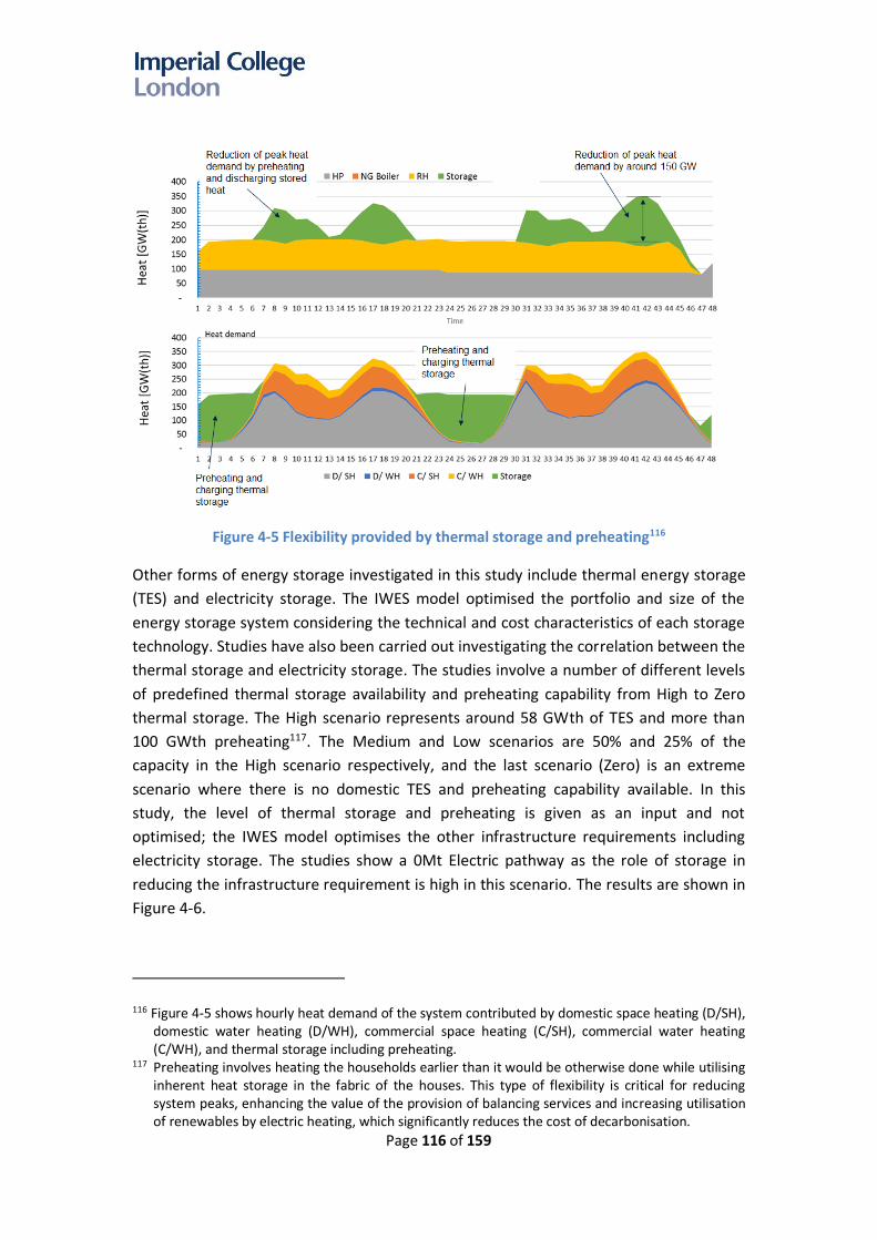
Page 116 of 159
Figure 4-5 Flexibility provided by thermal storage and preheating116
Other forms of energy storage investigated in this study include thermal energy storage
(TES) and electricity storage. The IWES model optimised the portfolio and size of the
energy storage system considering the technical and cost characteristics of each storage
technology. Studies have also been carried out investigating the correlation between the
thermal storage and electricity storage. The studies involve a number of different levels
of predefined thermal storage availability and preheating capability from High to Zero
thermal storage. The High scenario represents around 58 GWth of TES and more than
100 GWth preheating117. The Medium and Low scenarios are 50% and 25% of the
capacity in the High scenario respectively, and the last scenario (Zero) is an extreme
scenario where there is no domestic TES and preheating capability available. In this
study, the level of thermal storage and preheating is given as an input and not
optimised; the IWES model optimises the other infrastructure requirements including
electricity storage. The studies show a 0Mt Electric pathway as the role of storage in
reducing the infrastructure requirement is high in this scenario. The results are shown in
Figure 4-6.
116 Figure 4-5 shows hourly heat demand of the system contributed by domestic space heating (D/SH), domestic water heating (D/WH), commercial space heating (C/SH), commercial water heating (C/WH), and thermal storage including preheating.
117 Preheating involves heating the households earlier than it would be otherwise done while utilising inherent heat storage in the fabric of the houses. This type of flexibility is critical for reducing system peaks, enhancing the value of the provision of balancing services and increasing utilisation of renewables by electric heating, which significantly reduces the cost of decarbonisation.

Page 117 of 159
Figure 4-6 Correlation between TES and electricity storage
The modelling results demonstrate that in the absence of thermal storage and other
flexibility sources, there would be a need for more than 55 GW of new electricity
storage118 as well as substantial additional power system capacity in the Electric
scenario; however, if 58 GWth of TES (1.7 kWth/household) and preheating (more than
100 GWth) is available, the need for new electricity storage reduces to below 10 GW,
since the cost of thermal storage is considerably lower than the cost of electricity
storage and the cost of preheating is assumed to be applied at low cost. Smart control
could be installed to manage the operation of heating appliances and thermal storage
including preheating to minimise costs to consumers (and the overall system costs) while
maintaining the comfort levels. For example, preheating could be carried out when
there is surplus of low-carbon energy production while reducing the heat demand during
peak periods. Preheating and thermal storage also reduce the capacity of heating
appliances.
Although there is a strong interaction across different energy storage technologies
(electricity, gas, and thermal); these technologies may not be able to fully substitute for
the functionalities of other storage technologies. Storing energy in the form of electricity
can be more flexible than heat energy storage. For example, the batteries in the
electrified transport sector will provide services to local and national grid via the V2G
concept. Therefore, electricity storage is still needed (although with less capacity) even
with a large capacity of thermal storage.
118 Total storage capacity is 110 GWh.

Page 118 of 159
Another alternative energy storage is in the form of long-term thermal energy storage
(TES) is discussed in the next section.
4.3 Impact of long-term Thermal Energy Storage
The increased penetration of renewables in the UK attracts discussions on the use of
long-term thermal energy storage to store excess of renewable output over longer time
horizons. There are a number of long-term thermal energy storage technologies such as
underground thermal energy storage, pit storages, salt hydrate technology, phase-
change materials etc. The benefit and value of thermal energy storage technologies in
enabling the use of more variable and lower cost RES instead of higher-cost but firm
low-carbon generation such as nuclear has also been investigated through two cases
studies assuming the availability of TES that can store 10 and 20 days of heat demand.
The capacity of the TES is optimised by the IWES model. The modelling of long-term TES
is technology agnostic; it is assumed that there are no significant losses (cycle losses of
10%). The counterfactual (reference) scenario used in this comparison is the Electric 0Mt
case119 with zero flexibility. The results of the study are demonstrated in Figure 4-7.
Figure 4-7 Long-term thermal energy storage enables the integration of more renewables
The results demonstrate the following:
- Long-term thermal energy storage can facilitate the integration of larger volumes of
renewables, such as increased wind capacity. It is important to note that even though
the proposed capacity for PV is smaller, the utilisation of PV output is higher as less
curtailment will be needed during periods of high output. This is demonstrated in
Figure 4-8.
119 In this case, no system flexibility was assumed to be available in 0Mt Electric case

Page 119 of 159
Figure 4-8 Long-term thermal energy storage enables higher utilisation of renewables
- The ability to use more RES reduces the need for nuclear power, and therefore, the
installed capacity of nuclear in a system with thermal energy storage decreases (from
45 GW to 26 GW). This leads to a reduction in the share of nuclear power in the
energy mix as annual production falls from 336 TWh to 202 TWh (out of 748 TWh
total).
- There is a marginal difference between the results of a system with 10 days and 20
days of TES, suggesting that there is a limited additional benefit in having longer
duration energy storage (though much longer durations have not been considered)
The size of TES should be optimised to minimise the system cost.
Further studies investigating design options for long-term thermal storage would allow in-
depth understanding on the optimal ratings, energy storage capacities, and the impacts of
these technologies on the overall energy system.

Page 120 of 159
Chapter 5. Conclusions and policy
recommendations
5.1 Conclusions
The cost of each pathway and core variants are presented in ascending order in Table
5-1, for carbon targets of 30Mt and 0Mt.
Table 5-1 Cost performance of different decarbonisation pathways
30Mt scenarios Cost (£bn/year) 0Mt scenarios Cost (£bn/year)
Hybrid - H2 North 80.8 Hybrid 88.0
Hybrid 81.6 Hybrid - Urban DH HP 90.8
Hybrid - H2 Urban 85.4 Hybrid + micro-CHP 91.4
Hybrid - Urban DH HP 85.8 Elec 92.2
Hybrid + micro-CHP 87.2 Hybrid - H2 North 94.7
Elec 87.8 Elec+DH 97.7
H2 89.6 Hybrid - H2 Urban 101.4
Elec+DH 94.3 H2 121.7
H2+DH 111.6 H2+DH 142.2
For the 10Mt cases, the annual system costs are £84.8bn/year for the Hybrid case,
£89.5bn/year for the Electric case, and £90.2bn/year for the Hydrogen case.
It can be concluded that:
- A Hybrid pathway is identified as the most cost-effective decarbonisation pathway,
although the costs of the core decarbonisation pathways are relatively similar (the cost
difference is within 10%). Though it is worth noting that given the uncertainties
involved, the ranking may change when different assumptions apply.
- Systems with lower carbon emission targets will lead to higher costs. In all scenarios,
further emission abatement, from 30Mt to 10Mt, is available at limited additional
cost (the increased cost is between by 0.6 - 3.2 £bn/year). However, this changes
when moving from 10Mt to 0 Mt, with the cost further increases by £31.5bn/year in
the hydrogen scenario, compared to £2.7bn/year in the electric scenario.
- Electric and Hybrid pathways provide more optionality towards deep levels of
decarbonisation compared to the H2 pathway, given the shift in hydrogen production
from gas (ATRs) to electricity (electrolysers), which significantly increases the cost of
hydrogen infrastructure.

Page 121 of 159
- Regional scenarios for deploying hydrogen and district heating are more attractive than
national deployment for these specific solutions. In some cases, regional heat
decarbonisation choices – such as hydrogen in the North of GB, or district heating in
heat dense areas - within a wider national system can reduce overall costs.
- Technologies such as micro-CHP can provide alternatives to electric heating and
improve cross-energy flexibility between electricity and gas systems.
Considering the uncertainty across different heat decarbonisation pathways and
emissions targets, “low/no regrets”120 capacities of low-carbon generation technologies
across different pathways and emissions targets have been derived from the modelling
results. It indicates that there will be a minimum requirement of 5 GW of nuclear, 74 GW
of wind, and 3 GW of H2 CCGT across all pathways. Additional electricity generation
capacity will need to be built as the optimal generation portfolio will depend on many
factors such as costs, system flexibility, selected decarbonisation pathway and the
carbon target.
A range of sensitivity studies has also been carried out to assess the impact of different
assumptions on each decarbonisation scenario and its associated costs. The sensitivity
studies consider the influence of different discount rates, system flexibility, carbon
emissions targets, capex of low-carbon generation, heating demands, etc. In most of the
cases considered in the sensitivity analysis, the Hybrid scenario is identified as the least-
cost decarbonisation pathway; although the volume of gas reduces significantly the
value of existing gas infrastructure increases significantly by providing flexibility and
reducing significantly investment in electricity infrastructure. The Hybrid pathway is
generally more resilient to the sensitivities included in this analysis while the H2 and
Electric pathways would cause higher levels of disruption to households (requiring both
building upgrades, and disruption to streets with network upgrades).
In summary, the key findings of the modelling carried out are as follows:
• Towards a zero-carbon energy system, the cost-effective decarbonisation of heat may
require electrification
o Unless carbon capture rates involved in the production of hydrogen via gas
reforming can reach close to 100%, then decarbonising via hydrogen would
require significant investment in zero-carbon electricity generation in order to
produce hydrogen via electrolysis, which the analysis has demonstrated appears
to be expensive compared to other pathways
o Technology improvement in both carbon capture rates and efficiencies of gas-
based hydrogen production technologies would significantly reduce the cost of
hydrogen pathways, particularly in a 0Mt scenario.
120 Low/no regrets capacity is defined as the capacity that will be needed irrespective of the decarbonisation pathway adopted in the future.

Page 122 of 159
• Energy efficiency is of key importance
o Reducing heat demand by improving energy efficiency of buildings can reduce
system costs across all pathways.
• Towards a zero-carbon energy system, overall system costs will be dominated by the
capital expenditure, not operating costs
o Any measures that may reduce the capex (e.g. lower financing cost) will have a
significant impact
o Energy system pathways will be less sensitive than today’s energy systems to fuel
price variations, particularly in the Hybrid and Electric pathways.
• System flexibility is of key importance for cost-effective energy system
decarbonisation
- The absence of flexibility would increase system costs in the Electric 0Mt scenario by
more than £16 billion per year. The benefits of flexibility are highest in the Electric
scenario and lowest in the H2 pathway, as both H2 and Hybrid scenario involve some
inherent cross-vector flexibility, which reduces the benefits of other sources flexibility
as defined in the study. The study demonstrates that having 50% of potential
flexibility would already capture a significant proportion (70%-85%) of the benefits.
As the benefits are non-linear, initial improvements in flexibility have the highest
value; beyond 50% flexibility, the marginal value of additional flexibility diminishes.
o It is important to note that IWES model co-optimises electricity, gas, hydrogen and
heat systems, simultaneously considering both short-term operation and long-
term investment decisions covering both local district and national/international
level energy infrastructure, including carbon emissions and security of supply
constraints. Absence of IWES cross-vector coordination would significantly
increase costs of heat-decarbonisation. Hence the cross-vector flexibility and the
link between local and national levels services across different time-scales are
implicitly taken into account in all scenarios, and the benefits of flexibility
quantified in the study are related to other sources of flexibility (e.g. pre-heating,
smart-charging of EVs, etc).
o Co-ordinating system flexibility across electricity and gas systems reduces system
costs significantly, e.g. (i) the use of gas to supply heat during peak demand
conditions significantly reduces investment in electricity system infrastructure (ii)
hydrogen could be stored long-term and be used in the power system to reduce
the need for firm low carbon generation (e.g. nuclear); (iii) household level
flexibility around heat demand, facilitated by thermal energy storage and
application of preheating, would enhance the utilisation of renewable energy
resources and significantly reduce system capacity requirements.
o Stronger planning coordination between electricity, gas and heating systems is
needed to minimise whole-system costs.
o When electrolysers are needed (e.g. to produce hydrogen), electrolysers can
provide grid balancing services following the output of renewables. However, such

Page 123 of 159
flexibility can also be provided by demand response and storage hence the
decision to invest in electrolysers is not primarily driven by the need for grid
balancing but by converting energy from low-carbon electricity generation to
hydrogen which can then be stored more cost-effectively. Electrolysers have
important role in H2 0Mt case but are less critical in other pathways.
• Energy storage can reduce system capacity requirements and facilitate the cost-
effective deployment of renewables.
o Storage can be used to improve load factors of baseload power generation and
hydrogen production plants; the cost of storage is typically much lower than the
capex of baseload plant, and therefore it can provide capacity at lower cost. The
modelling results demonstrate that hydrogen storage is essential to maintain
steady production in gas-reforming plants that produce hydrogen, reduce the
need for hydrogen production capacity and its associated cost, provide cost-
effective both short and long-term energy storage as a supplement or an
alternative to other energy storage technologies (e.g. electricity storage and
thermal storage). A hydrogen network provides significant ‘linepack’ storage of
hydrogen.
o Hydrogen storage can provide both short and long-term energy balancing services,
which will facilitate more effective integration of RES.
o The modelling results demonstrate that in the absence of thermal storage and
other flexibility, there would be a need for more than 55 GW new electricity
storage in the Electric scenario; however, if 58 GWth of TES (1.7 kWth/household)
and preheating (more than 100 GWth) are available, the need for new electricity
storage reduces to below 10 GW, since the cost of preheating and thermal storage
(e.g. hot water tanks, phase-change-material based thermal storage) is lower than
the cost of electricity storage.
• Importing low-cost hydrogen could potentially make the H2 pathway cost competitive
against electrification pathways; though producing hydrogen at the costs assumed in
this analysis would require a significant reduction in the cost of electrolysis and
shipping hydrogen. Imports of hydrogen could also reduce the need for UK based
hydrogen storage.
• Economies of scale of investment are also important for achieving minimum overall
cost. The modelling assumes that both electricity and hydrogen is produced on a
centralised, rather than a distributed basis. More localised production would result in
lower economies of scale, increasing system costs.
• Gas network modelling suggests that additional network level storage of distributed
hydrogen (131 – 333 GWh) is required to enable transport of hydrogen through high-
pressure distribution gas networks. This would increase the cost of the H2 pathway
for approximately £0.35bn/year to £0.61bn/year. While the total volume required is
relatively small, the distribution of these storages is important for consideration.

Page 124 of 159
Therefore, this investment cost is in addition to significant investment in large-scale
storage facilities in the H2 scenarios.
5.2 Policy implications and recommendations
A set of recommendations are outlined below, based on the modelling results and
analysis carried out in this study.
5.2.1 Further analysis
In order to provide an in-depth understanding of the transition towards low carbon heat,
a number of areas may warrant further investigation. These could include:
• Detailed analysis of different types of buildings considering typical heat requirements,
levels of insulation, the role of thermal storage, etc. Following this, a further
assessment of corresponding system performance and costs could be made.
• Further investigation of alternative decarbonisation pathways that involve diversified
(“patchwork”) heating solutions across different regions in the UK, and the impact
these could have on national low-carbon heating choices. In the context of heat-
sector decarbonisation it may be appropriate to investigate if the concept of levelized
cost of end use heat technologies could be introduced to inform corresponding policy
development.
• Development of robust least-worst heat decarbonisation pathways and
corresponding policies, while considering explicitly a full range of technologies and
system uncertainties.
• The resilience of the future energy systems considering high impact events such as
extreme weather conditions, shortage of gas supply, etc.
• Role, value and business cases of emerging technologies such as Phase Change
Material-based thermal energy storage, co-optimisation of energy for cooling and
heating, research into long-term thermal energy storage technologies.
• Assessing the significance of the integration of transport and heat sectors through the
vehicle-to-home / vehicle-to-grid concepts, and the impact on the need for thermal
storage.
• Investigation into the operation and costs of managing the gas grid with reduced
flows of gas (i.e. in the hybrid heat pump scenarios).
• Further research into the implications for further energy efficiency requirements –
beyond what the CCC has assumed – across these heat decarbonisation pathways.
• Investigation in greater detail of the scope for H2 imports; this should include
consideration of costs of solar PV, electrolysers, water productions, etc., marine
transport, storage (ammonia versus liquid H2) and different locations (North Africa,
Middle East, South Africa, Australia).

Page 125 of 159
• Further research related to the provision of system inertia is needed to investigate
the impact on the optimal portfolio of generation technologies, particularly in 0 Mt
case, as the provision of synthetic inertia (e.g. by wind generation) could reduce the
optimal volume of nuclear, while on the other hand, coordinated de-loading of
nuclear generation during low demand and high renewable output conditions would
reduce the size of the largest loss and hence enhance the value of nuclear generation.
5.2.2 Decarbonisation of electricity supply and enhancement of system
flexibility
The studies demonstrate that the decarbonisation of electricity generation and
improvement of system flexibility are essential, irrespective of the heat decarbonisation
strategy. As the present renewable capacity, around 40 GW in total, is significantly lower
than the no-regret capacity121 (see discussions in section 2.5), this implies that the
decarbonisation of electricity supply should be continued. In the short term, the
development of low-carbon generation can focus on renewable power. In the medium
and long-term, firm low-carbon capacity should be deployed to meet low emission
carbon targets. Technologies such as nuclear, CCS and hydrogen-based CCGT/OCGT
should be considered. Increased penetration of low-carbon generation capacity should
be accompanied with increased flexibility in the system to minimise its system
integration costs. Further knowledge and practical experience should be gained by
trialling smart control systems in buildings in order to enhance the system flexibility.
5.2.3 Policy development for heat decarbonisation
At present, there is a large-scale programme underway for the decarbonisation of the
electricity supply sector (i.e. a support mechanism for investment in low carbon
generation). In order to facilitate investment in low-carbon heating appliances such as
hydrogen boilers, heat pumps or hybrid heat pump, it would be important to review and
develop further policy guidance and/or financial incentives - including the Renewable
Heat Incentive (RHI)122 - to individual end-users and/or energy communities in order to
encourage and reward investment in low-carbon heating technologies. Furthermore, the
price of electricity reflects the carbon content of the fuel mix, which is not the case for
household currently on fossil fuel-based heating systems. A carbon price on heat should,
therefore, be considered. In this context, it will be important to investigate the CO2
reductions that could be achieved by demand-side focussed strategies, e.g. radical
building energy efficiency programs.
121 See discussions in section 2.5 122 RHI provides financial incentive to promote the use of renewable heat including heat pumps.

Page 126 of 159
5.2.4 New market design for flexibility
As demonstrated in this study, cross-energy system flexibility will be critical for
facilitating a cost-effective transition to a low-carbon energy system (i.e. a reduction in
investment in low carbon generation and energy conversion technologies, a reduction in
system operating costs and investment in system capacity needed to meet the peak
demand). In the electricity sector, there are several emerging markets focusing on new
flexibility products (such as fast frequency response, demand-response reserve services,
etc.). These initiatives should be extended through the development of cost-reflective
flexibility markets123 with appropriate spatial and temporal resolutions, that would link
all energy vectors and facilitate competition between alternative solutions on a level
playing field.
Furthermore, as demonstrated in the modelling, flexibility technologies and systems can
reduce the amount of low-carbon generation needed to meet the carbon targets.
However, suitable remuneration mechanisms for this value stream do not exist in the
current market (and are not considered in the Electricity Market Reform). Such
mechanisms should be developed to allow new flexible technologies to access revenues
associated with a reduction in investment in low carbon generation through establishing
the link between energy market and low-carbon agenda.
5.2.5 Pilot trials
One of the key conclusions from the studies carried out is that none of the heat
decarbonisation pathways can be excluded as options for large-scale deployment, due to
the proximity of overall system costs across the pathways within a significant level of
uncertainty. Therefore, the focus of any action should be to address
uncertainties. Knowledge and experience that will be gained from deployment at scale
(i.e. 10,000s of households) will provide critical insights into the strengths and
weaknesses of alternative approaches to heat decarbonisation and the technologies
involved. Hence consideration should be given to a programme of technology
deployment on a pilot trial basis. These initiatives should be designed to encompass all
aspects of deployment - from production through to end-users - while including all types
of representative buildings within the UK.
5.2.6 Carbon emission targets for energy
The studies illustrate the impact of reducing carbon emissions from energy from 30Mt to
0Mt – without decarbonisation of the heating system, residual emissions could be over
100 MtCO2, which is incompatible with the UK’s 2050 target. In the long-term, reducing
energy system emissions to zero may be required to support other sectors that cannot
123 This is coherent with the recommendation in the Pöyry and Imperial College’s report to CCC: “Roadmap for Flexibility Services to 2030”, May 2017.

Page 127 of 159
achieve their share of the required greenhouse gas reductions. The consequence of this
would be to substantially reduce natural gas-based technologies such as gas reforming
and gas generation and would, therefore, require considerably more zero-carbon
electricity generation technologies such as nuclear power and renewables, combined
with energy storage. However, progress with importing hydrogen at low costs, or
improving the efficiencies and carbon capture rates of gas reforming technologies could
mitigate the need to build additional low-carbon electricity generation. This hydrogen
production options warrant further investigation.
5.2.7 Hydrogen production demonstration plants
The two hydrogen production technologies for large-scale deployment are currently gas
reforming and electrolysis. Although there is considerable experience of gas reforming it
is limited to industrial applications. There is insufficient experience of electrolysis. In
both cases, there is considerable uncertainty in terms of costs and performance,
particularly for large-scale deployment. It would be informative to commit to build gas
reforming and electrolysis demonstration plants within the UK to enable experience to
be gained prior to making decisions on large-scale deployment.

Page 128 of 159
Appendix A. Costs of alternative
decarbonisation
pathways
Figure A-1 shows the detailed cost comparison across a range of heat decarbonisation
pathways discussed in section 2.4. Unless otherwise stated, all costs are expressed in
terms of annual cost in real 2017 money. The capital costs are annuitized using the
relevant discount factors, taking into consideration the economic life-time of the assets.
The annual cost includes the fixed operating and maintenance cost.
Figure A-1 Annual system cost components of hydrogen pathways in different cases
There are 29 cost components considered in the model, i.e.:
1. The capital cost of low-carbon generation [C: Low-carbon gen] which includes
the capital cost of wind, PV, hydro, nuclear, CCS and H2-based generation.
2. The capital cost of non-low carbon generation [C: Non-low-carbon gen] which
includes the capital cost of traditional fossil-fuel based generation such as CCGT,
OCGT and CHP.

Page 129 of 159
3. The capital cost of transmission [C: Transmission] which includes the cost of GB
transmission network.
4. The capital cost of interconnection [C: Interconnection] which includes the cost
of GB interconnectors.
5. The capital cost of distribution [C: Distribution] which includes the cost of
reinforcing electricity distribution network.
6. Operating cost of electricity generation [O: Electricity] which includes the fuel
cost, no-load cost and start-up cost of power generation.
7. The capital cost of heat pump [C: HP] – this includes the cost of heat pump
devices, installation cost and the annual fixed operating and maintenance cost.
8. The capital cost of resistive heating [C:RH] - this includes the cost of resistive
heating devices, installation cost and the annual fixed operating and
maintenance cost.
9. The capital cost of electricity storage [C:Storage] which includes the cost of
electricity storage in the system.
10. The capital cost of heat storage [C:Heat storage] which consists of the cost of
domestic and district heating TES.
11. Conversion cost associated with replacing gas-based heating to electric heating
[C: End-use HP conversion] which includes the cost of decommissioning gas-
based heating systems and replacing the gas units (e.g. gas oven, gas hob) with
the electrical appliances.
12. Cost of decommissioning gas distribution – this cost occurs only in the Electric
scenario as the gas distribution network is no longer used and therefore, it
should be decommissioned. The cost is estimated at £1bn/year.
13. The capital cost of H2 production technologies excluding electrolysis [C:
SMR/ATR/Bio] which includes the capital cost of building SMR, ATR, and the
biomass gasification with CCS.
14. The capital cost of electrolysers [C:Electrolysis] which includes the capital cost of
various electrolysers.
15. The capital cost of H2 network [C:H2 network] which consists of the cost of
building national H2 transmission network.
16. The capital cost of CCS network [C: CCS network] which includes the cost of
building the CCS network.
17. The capital cost of H2 storage [C:H2 storage] which consists of the capital cost of
both underground and overground storage.
18. The capital cost of carbon storage [C: Carbon storage] which includes the cost of
storing carbon captured by CCS. It is assumed that the cost of carbon storage is
£15/tCO2.
19. Operating cost of SMR/ATR [O:SMR/ATR] which includes the fuel cost used by
SMR/ATR to produce H2.
20. Cost of H2 import [O:H2 import]

Page 130 of 159
21. Operating cost of H2 storage [O:H2 storage]
22. Operating cost of NG-based boilers [O:NG boiler] which includes the fuel cost,
i.e. the cost of natural gas used by the boilers.
23. The capital cost of NG-based boilers [C:NG boiler] which includes the cost of
natural-gas-based boilers, installation, and the operating and maintenance costs.
24. The capital cost of H2-based boilers [C:H2 boiler] which includes the cost of H2
based boilers, installation, and the operating and maintenance costs.
25. The capital cost of district heating network [C:DH (network)] which includes the
operating and maintenance cost of the district heating network.
26. The capital cost of district heating household appliances [C:DH (appliance) which
includes the cost of household heat infrastructure needed for the district heating
system, e.g. metering, heat control, and connection to the main heat network.
27. The conversion cost needed to replace the existing house heating system with
H2-based district heating [C: DH (conversion)] – this is associated with the cost of
decommissioning natural-gas appliances and replacing it with electric appliances,
e.g. replacing the gas hob and gas oven to an electric hob and oven and to add
the hot-water storage system.
28. The capital cost of gas distribution [C: gas distribution] – this is the cost of
retaining the present gas distribution network. This is applied to the H2 and
Hybrid pathways.
29. Conversion cost needed to replace the existing house heating system with H2-
based heating (H2 boiler) [C:End-use H2 conversion] – this is associated with the
cost of decommissioning natural-gas appliances and replacing it either with H2-
compliance or electric appliances.
The following tables provide more detailed information about the costs , optimal capacity
and energy production in the core heat decarbonisation scenarios.

Page 131 of 159
Cost (in million £/year) H2 [30] H2 [10] H2 [0] Elec [30] Elec [10] Elec [0] Hybrid [30] Hybrid [10] Hybrid [0]
C: Low carbon gen 18,505 21,650 48,896 32,911 37,281 40,858 33,452 38,357 41,294
C: Non low-carbon gen 2,835 2,465 2,655 4,963 4,076 2,784 2,455 1,726 1,223
C: Transmission 855 880 902 1,026 917 865 930 880 868
C: Interconnnection 1,515 1,515 1,786 1,786 1,786 1,786 1,515 1,786 1,786
C: Distribution 956 920 3,321 6,397 6,240 5,877 1,322 1,553 1,829
O: Electricity 3,351 1,163 2,172 4,365 2,670 2,164 2,437 1,842 1,780
C: HP 3,977 3,985 4,236 25,431 25,624 26,063 17,085 17,182 17,561
C: RH 347 342 283 1,800 1,674 1,478 854 900 886
C: Storage 243 269 800 510 495 521 64 96 196
C: Heat storage 1,288 1,235 1,730 2,393 2,266 2,342 1,089 1,187 1,233
C: End-use HP conversion - - - 1,935 1,935 1,935 - - -
C: Decom. gas distribution - - - 1,000 1,000 1,000 - - -
C: SMR 8,030 8,029 9,386 2,769 2,769 3,452 2,769 2,799 3,394
C: electrolysis 58 136 13,726 2 1 4 1,276 1,286 1,245
C:H2 network 592 582 509 - - - - - -
C:H2 storage 6,441 6,415 4,823 155 403 699 455 523 835
C:CCS network - - - - - - - - -
C:Carbon storage 2,307 2,303 815 311 311 311 311 311 311
O: SMR 17,123 17,092 4,334 - - - - - -
O:H2 storage 3 3 6 0 0 0 1 1 1
O: NG boiler - - - - - - 2,329 1,194 458
C: NG boiler - - - - - - 8,452 8,410 8,366
C: H2 boiler 12,098 12,099 12,251 - - - - - -
C: Gas distribution 4,733 4,733 4,733 - - - 4,733 4,733 4,733
C: End-use H2 conversion 4,325 4,325 4,325 - - - - - -
C: DH (network) 41 41 41 41 41 41 41 41 41
Total 89,623 90,181 121,731 87,794 89,490 92,182 81,569 84,806 88,041

Page 132 of 159
H2 [30] H2 [10] H2 [0] Elec [30] Elec [10] Elec [0] Hybrid [30] Hybrid [10] Hybrid [0]
Electricity demand (TWh/year)
Non-transport and non-heat demand 306 306 305 306 306 306 306 306 306
Electric heating 28 28 27 280 280 280 208 235 254
Electric transport 111 111 111 111 111 111 111 111 111
Smart domestic appliance 62 62 62 62 62 62 62 62 62
Electrolyser 1 4 441 0 0 0 48 48 48
Storage 6 9 0 8 8 8 4 4 6
Total 514 519 946 767 766 767 739 766 787
Electricity generation (GW)
H2 CCGT 12 14 3 12 15 23 7 8 14
H2 OCGT 0 0 5 27 27 24 8 10 9
NG CCGT 30 19 11 41 28 13 26 11 0
NG OCGT 15 21 6 106 98 79 9 11 13
Post-combustion CCS 0 0 0 0 0 0 0 0 0
Nuclear 5 5 45 13 27 43 19 35 45
Wind 77 92 120 117 104 74 115 98 82
PV 63 76 150 146 128 129 110 99 103
Hydro 1 1 1 1 1 1 1 1 1
Storage 7 8 18 12 12 12 4 4 6
District CHP 8 9 18 0 0 0 8 8 8
Total 211 237 360 476 440 399 299 277 273

Page 133 of 159
H2 [30] H2 [10] H2 [0] Elec [30] Elec [10] Elec [0] Hybrid [30] Hybrid [10] Hybrid [0]
Electricity generation (TWh/year)
H2 CCGT 50 50 0 54 54 54 34 34 34
H2 OCGT 0 0 0 0 0 0 0 0 0
NG CCGT 74 19 10 80 30 5 41 11 0
NG OCGT 1 2 0 7 5 4 0 0 0
Post-combustion CCS 0 0 0 0 0 0 0 0 0
Nuclear 39 42 354 104 213 340 148 273 354
Wind 253 298 408 383 340 241 383 323 270
PV 56 65 139 124 109 108 95 86 89
Hydro 8 8 8 8 8 8 8 8 8
Storage 5 7 0 6 6 6 3 3 4
District CHP 28 28 26 - - - 28 28 28
Total 514 519 946 766 766 767 739 766 787
Heating (TWh of heat delivered)
NG Boiler - - - - - - 92 48 18
H2 Boiler 532 532 532 - - - - - -
RH 6 6 5 52 51 51 19 32 44
District CHP 40 40 38 - - - 39 39 39
HP 56 56 57 556 556 557 492 525 545
District HP 0 0 0 41 40 40 0 0 0
Total 634 634 632 648 648 648 644 645 646

Page 134 of 159
H2 [30] H2 [10] H2 [0] Elec [30] Elec [10] Elec [0] Hybrid [30] Hybrid [10] Hybrid [0]
H2 production capacity (GW)
ATR + CCS 90 90 90 - - - - - -
Electrolyser 1 2 106 0 0 0 10 10 10
Biomass + CCS 12 12 18 12 12 15 12 12 14
H2 production (TWh)
ATR + CCS 663 661 168 - - - - - -
Electrolyser 1 3 406 0 0 0 44 44 44
Biomass + CCS 93 93 93 93 93 93 93 93 93
Biogas (TWh)
Biogas 21 21 21 21 21 21 21 21 21
H2 storage (GWh)
Underground 17,827 17,582 11,489 3 2 7 231 287 418
Overground (medium pressure) 1,733 1,756 1,501 128 334 578 335 382 616

Page 135 of 159
Appendix B. Household
conversion and
heating appliance cost The household conversion and heating appliance costs used in this study are presented
in the following table.
Table B-1 Household conversion and heating appliance cost
Action required H2 heating £3k including
gas pipe upgrade
Electric - Heat pump (5kWth)and resistive heating (1 kWth), preheating
(3.6 kWth), thermal storage
(1.7 kWth)
Hybrid heat pump with natural gas
(HP:4 kWth, gas boiler: 10kWth,
thermal storage: 1.7kWth)
Small heat pump (£1k/kWth) with supplementary electric heating
(£.2k/kWth) (Assume 5kWth
for heat pump and 5kWth for electric
heating ) £6k
District heating £6.8k
Resistive heating £150/kWth
(Assume 10kWth)
Hybrid resistive heating with natural gas
(RH:4 kWth, gas boiler: 10kWth,
thermal storage:
1.7kWth)
Decommission and/ or replace gas/oil boiler 24.9M (est.)
Yes – boiler will require replacing in order to operate on hydrogen
Yes – if a gas boiler is already installed it will require decommissioning - £0.5k
Not necessarily – gas boiler could be retained to operate as a bivalent system or for a unit HHP included in cost
Yes – if a gas boiler is installed it will require decommissioning - £0.5k
Yes – if a gas boiler is installed it will require decommissioning - £0.5k
Yes – if a gas boiler is installed it will require decommissioning - £0.5k
Not necessarily – gas boiler could be retained to operate as a bivalent system or for a unit HRH included in cost
Decommission and/or replace gas hob 14.8M2 or 59% See T3.12
Yes – no evidence that hydrogen can operate safely on open flame devices. Replace with electric hob - £0.5k
Yes – if a gas hob is installed it will require decommissioning and replacing with an electric hob - £0.5k
No – but this would add about 0.4MWhpapto consumer gas demand for gas hob
Yes – if a gas hob is installed it will require decommissioning and replacing with an electric hob - £0.5k
Yes – if a gas hob is installed it will require decommissioning and replacing with an electric hob - £0.5k
Yes – if a gas hob is installed it will require decommissioning and replacing with an electric hob - £0.5k
No – but this would add about 0.4MWhpapto consumer gas demand for gas hob
Decommission and/or replace gas oven 8.4M3 or 34% See T3.12
Yes – no evidence that hydrogen can operate safely on open flame devices. Replace with electric oven - £0.5k
Yes – if a gas oven is installed it will require decommissioning and replacing with an electric oven - £0.5k
No – see above 0.2MWhpa
Yes – if a gas oven is installed it will require decommissioning and replacing with an electric oven - £0.5k
Yes – if a gas oven is installed it will require decommissioning and replacing with an electric oven - £0.5k
Yes – if a gas oven is installed it will require decommissioning and replacing with an electric oven - £0.5k
No – see above 0.2MWhpa
Decommission and/or replace other gas appliances Assume 23.9M4 or 96% See T3.18
Yes – no evidence that hydrogen can operate safely on open flame devices. Replace with electric appliance - £0.5k
Yes – if other gas appliances are installed they will require decommissioning and replacing with an electric appliances (note 6)
No but this would add to consumer demand
Yes – if other gas appliances are installed they will require decommissioning and replacing with an electric appliances (note 6)
Yes – if other gas appliances are installed they will require decommissioning and replacing with an electric appliances (note 6)
Yes – if other gas appliances are installed they will require decommissioning and replacing with an electric appliances (note 6)
No but this would add to consumer demand
Replace/ upgrade / decommission (wet) heat emitters
No Yes replacing/ upgrading required to compensate for lower flow temperatures (note 7)
No Yes replacing/ upgrading required to compensate for lower flow temperatures - £0.5k
No Yes – heat emitters will require decommissioning - £0.5k
No
Replace/ install hot water system with storage Assume 13.9M5 (est.) See T3.19
No Yes – hot water storage will be required but assume it is included with heat pump. Domestic TES: 1.7kWth [£0.34k]
No but this would add 2MWhpa to consumer gas demand
Yes – hot water storage will be required but assume it is included with heat pump
Yes – hot water storage will be required - £1k
Yes – hot water storage will be required - £1k
No but this would add 2MWhpa to consumer gas demand

Page 136 of 159
Action required H2 heating £3k including
gas pipe upgrade
Electric - Heat pump (5kWth)and resistive heating (1 kWth), preheating
(3.6 kWth), thermal storage
(1.7 kWth)
Hybrid heat pump with natural gas
(HP:4 kWth, gas boiler: 10kWth,
thermal storage: 1.7kWth)
Small heat pump (£1k/kWth) with supplementary electric heating
(£.2k/kWth) (Assume 5kWth
for heat pump and 5kWth for electric
heating ) £6k
District heating £6.8k
Resistive heating £150/kWth
(Assume 10kWth)
Hybrid resistive heating with natural gas
(RH:4 kWth, gas boiler: 10kWth,
thermal storage:
1.7kWth)
Indicative building maximum space heating demand?
Not essential for heating performance
10MWhpa 10MWhpa 10MWhpa Not essential for heating performance
7MWhpa 10MWhpa
Appliance cost (see note 7-11)
£3.0k £5.0k £6.0k £6.0k £6.8k £1.5k £3.6k
Conversion costs (see note 12)
£1.0k £1.0k £0.0k £1.5k £1.0k £2.5k £0.0k
Total costs £4.0k £6.0k £6.0k £7.5k £7.8k £4.0k £3.6k
Notes:
1. 23.9M gas and 1.0M oil households with boilers - see T3.18 in ECUK_2017
2. There are 12.2M electric hobs and 3.1M households without gas and so must
have electric hobs. Hence 9.1M gas households have electric already leaving
14.8M with gas hobs.
3. There are 18.6M electric ovens and 3.1M households without gas and so
must have electric ovens. Hence 15.5M gas households have electric already
leaving 8.4M with gas ovens.
4. There are 23.9M gas households so assume all have at least one other gas
appliance.
5. There are 13.9M households with combination boilers and so assume there
is no hot water storage.
6. Following discussion with CCC, the cost of decommission other gas
applianced is included in the cost of decommissioning gas boiler.
7. The cost is included in the installation cost of heat pump.
8. Cost of H2 boiler is £3000/household.
9. Cost of Electric heating is around £5k/household. This includes the cost of
5kWth HP (£3000), 1kWth RH (£120), 1.7 kWth TES(£340), installation cost
(£1500).
10. Cost of Hybrid Heat Pump is around £6k/household. This includes the cost of
4kWth HP(£2700), NG boiler (£750), TES(£340), installation cost (£2200)]. A
conservative assumption is taken that the cost of 4 kW HP is 90% the cost of
5 kW HP. The cost does not decrease linearly.
11. Cost of Hybrid resistive heating is around £3.6k/household. This includes the
cost of 4kWth RH(£480), NG boiler (£750), TES(£340), installation cost
(£2000).
12. If both gas oven and gas hob need to be decommissioned and replaced with
electric hob and oven, the cost remains £0.5k.
13. Another scenario that has been analysed in the Hybrid pathway, involves 10
GW of fuel cell based micro-CHP. In this scenario, the cost of micro-CHP is

Page 137 of 159
assumed to be £2500/kW(e), with the installation cost of £1000/household
with the operating and maintenance cost of £100/year. The capacity of
micro-CHP per household is 3 kW; also hydrogen boiler is used. The
household conversion cost for households with micro-CHP is the same as in
the H2 pathway.
The cost of heat networks in the district heating study is based on the BEIS report in
2015124.
124 Department of Energy and Climate Change, “Assessment of the Costs, Performance, Characteristics of UK Heat networks,” 2015. https://assets.publishing.service.gov.uk/government/uploads/system/uploads/attachment_data/file/424254/heat_networks.pdf

Page 138 of 159
Appendix C. Heat demand
sensitivities
Figure C-2 Housing insulation pathway with 10% improvement in existing housing insulation
Figure C-1 shows an estimate of UK housing insulation pathway by date of construction
and number of households against their heat loss parameter (W/m2K) with a 10%
improvement in existing (up to 2015) housing insulation by 2050. Added to the figure
are projections of future housing stock with assumptions on insulation levels. It can be
seen that based on these assumptions the weighted average housing insulation falls
from the current level of 3.12 W/m2K to 2.32W/ W/m2K, ~26% by 2050. This
improvement is more than the projected increase in households (from 27.1 M to 32.9
M125 households) and so the overall impact is a small reduction in national annual
household heat demand.
A “Low demand” sensitivity was constructed based on a 30% improvement in existing
household insulation levels. This is shown in figure C-2 and results in a reduction in the
weighted average housing insulation from the current level of 3.12 W/m2K to 2.55
125 This number was used in a different study to project the impact of increased future housing stock on the space heating demand. The number of households used in the main studies is 34.4M.

Page 139 of 159
W/m2K, ~40% by 2050. This more than offsets the increase in the number of households
and results in a reduction in annual household heat demand from 349 TWh to 290 TWh
by 2050.
Space heating demand is very much affected by external temperature. UK climate
projections 2009 (UKCP09126) includes changes in winter mean temperatures of ~+2°C.
Applying a Climate Change Adjustment (CCA) based on this increase and assuming no
change to other influencing variables results in an estimated reduction in annual
household heat demand from 290 TWh (Low demand) to 234 TWh (Low demand with
CCA).
Figure C-2 Housing insulation pathway with 30% improvement in existing housing
insulation
126 Murphy, JM et al (2009) UK Climate Projections Science Report: Climate change projections

Page 140 of 159
Appendix D. Feasibility of
transporting
hydrogen using
existing gas
distribution system
D.1 Objective
Hydrogen’s volumetric energy density is only around 30% of the volumetric energy
density of natural gas. This implies that more than three times volume of gas (hydrogen)
has to be supplied to consumer premises via gas distribution networks to meet the same
energy demand. This raises a question whether the existing capacity of gas distribution
networks, if it is converted into hydrogen networks, can be used for hydrogen transport
without significant reinforcement. The objective of this study is to investigate the
technical capability of the existing gas distribution networks at various pressure tiers (i.e.
high, medium and low pressure) to transport hydrogen instead of natural gas. In
particular, this study (a) examines whether the existing gas distribution networks are
capable of meeting peak energy demand via hydrogen and (b) quantifies the GB-wide
hydrogen storage capacity required to meet heat demand. Safety issues, leakage rates
related to the use and transporting hydrogen are important issues but not in the scope
of this analysis.
A gas network-modelling tool was developed to analyse and compare transporting
hydrogen and natural gas in a number of test networks. The capacity of hydrogen
storage required to enable the distribution networks to meet peak energy demand using
hydrogen was quantified for the test networks. The hydrogen storage capacity for the
test networks was used to extrapolate required storage capacity for hydrogen across
Great Britain’s gas distribution systems. The modelling results suggest between 131
GWh to 333 GWh127 distributed hydrogen storage capacity is required to enable the
existing gas distribution networks across GB to meet the energy demand using
hydrogen. While the total volume is relatively small (less than 5% of the overall gas
storage capacity in the UK), the location of storage is also important to ensure sufficient
local hydrogen supply capacity.
127 It requires around 40-100 mcm of gas storage.

Page 141 of 159
D.2 Methodology
To examine whether the existing gas distribution networks are capable of meeting
energy demand using hydrogen, and investigate required expansion in terms of
hydrogen storage, a methodology, shown in Figure D-1, was proposed. The proposed
methodology consists of three main steps: (1) a modelling tool based on Combined Gas
and Electricity Networks (CGEN) model128 was developed for analysing hydrogen and
natural gas transport via distribution pipelines, (2) a number of test networks
representing low, medium and high pressure gas distribution networks were modelled
and the hydrogen storage capacity required for these networks to meet peak energy
demand was quantified, and (3) using regression models, hydrogen storage capacity for
local distribution zones across GB was estimated.
Figure D-1 Structure of the methodologies
Different steps of the methodology are described below.
D.1.1 Gas network modelling
Figure D-2 shows the structure of the model that was developed to analyse the
operation of distribution networks for natural gas and hydrogen. The gas network model
was developed based on the Combined Gas and Electricity Networks model (CGEN). The
model is able to simulate gas networks at various pressure tiers for natural gas and
hydrogen.
128 M. Qadrdan, H. Ameli, G. Strbac, and N. Jenkins, “Efficacy of options to address balancing challenges: Integrated gas and electricity perspectives,” Appl. Energy, vol. 190, 2017
MODEL DEVELOPMENT: A modelling tool for analysing hydrogen transport via pipelines was developed.
H2 NETWORK SIMULATION: A number of test networks representing, Low, Medium, and High pressure gas distribution networks were analysed, and H2 storage capacity required was quantified.
Estimation of required H2 storage capacity across GB’s gas distribution networks: By extrapolating the modelling results for the test networks, aggregate H2 storage capacity required at each offtake was estimated for a number of future scenarios.

Page 142 of 159
Figure D-2 Structure of the model for analysing gas networks operation
A sequential steady-state model was developed to analyse the detailed operation of
natural gas and hydrogen distribution networks.
D.3 Case studies
A number of test networks representing various pressure tiers are modelled to analyse
the impacts of transporting hydrogen and quantify the required hydrogen storage
capacity. The test networks include three low-pressure networks (LP#1, LP#2 and LP#3),
one medium pressure network (MP) and three high-pressure networks (HP#1, HP#2 and
HP#3). Detailed information of the test networks including the network topology (pipes
connection) and characteristics (pipes length and diameter), and energy demand is
provided in Appendix E.
For each test network, two simulations were conducted: (1) Natural Gas: transporting
100% natural gas, and (2) Hydrogen: transporting 100% hydrogen. As the networks are
primarily designed to meet the peak energy demand using natural gas, they have no
unserved energy in NG cases. The network simulation results for hydrogen transport (H2
cases) inform if the networks are also capable of using hydrogen to meet peak energy
demand. The additional hydrogen storage capacity needed to enable the distribution
systems to meet energy demand using hydrogen were calculated based on the total
amount of unserved hydrogen in H2 cases.
D.4 Key results
D.4.1 Impacts of hydrogen transport on low-pressure networks
The modelling results for LP#1 (Figure D-4) and LP#2 (Figure D-6) show that the
transportation of larger volume of hydrogen has negligible impacts on the networks’
pressure profiles (see Figure D-3 and Figure D-5) and consequently their capability to
meet energy demand. This is mainly due to the lower specific gravity of hydrogen

Page 143 of 159
compared to natural gas which makes the hydrogen to travel faster along a pipe. Given
the small size of the LP systems (short pipelines), almost the same pressure difference
across a pipe establish three times larger volumetric flow for hydrogen compared to
natural gas. Therefore, it can be concluded that transporting hydrogen using the existing
low-pressure distribution networks (assuming the energy demand remain unchanged) is
feasible from the supply capacity point of view. For example, at node 11, which is the
farthest node from the supply point (node 1), the absolute pressure of hydrogen is
insignificantly smaller than the pressure of natural gas. The same finding is also observed
in the case of LP#2 system which has a more complex system topology.
Figure D-3 Pressure profile for NG and H2 in LP#1 Figure D-4 Low-pressure network
#1 (LP#1)
Figure D-5 Pressure profile for NG and H2 in
LP#2
Figure D-6 Low-pressure network #2
(LP#2)
D.4.2 Impacts of hydrogen transport on medium pressure networks
Similar to the LP networks, our analysis shows in the MP network, there is no significant
difference between pressure profiles of H2 and NG cases. Therefore, the transport
capacity of the network is not affected. Figure D-7 shows the pressure profile across the
MP network (Figure D-8).
1
25 4
36 7 9
10
11
8
Supply
874 5321
75
64
26
57
17
52
45
22
31
67
99
98
84
88
74
93
94
97
201918
272625
352
352
5655
636261
727170
9291
87
112
24
2
5453
46
47
33 34
23
35
6968
60
8685
9089
6
32
100 101
102 103
104
105
106 107
108109 110 111
113
114115
Supply 1
Supply 2

Page 144 of 159
Figure D-7 Pressure profile for NG and H2 in MP
Figure D-8 Medium pressure network (MP)
D.4.3 Impacts of hydrogen transport on high-pressure networks
Three high-pressure test networks were simulated (Figure D-9). The simulation results
show, for all the HP test networks, using hydrogen to meet the peak energy demand
would result in unserved energy. Unlike, low and medium pressure networks in which
the size of the networks are small, and therefore the within pipes storage is negligible, in
the high-pressure networks the within pipes storage or ‘linepack’ plays a crucial role in
meeting energy demand during peak hours. The lower density of hydrogen compared to
20
21
23
22
9
368634
24
19
1211107
43
2
33
29
26
251814132
15
16
5235
13
31 30
28
27
17
Supply

Page 145 of 159
natural gas reduced the available linepack in the HP networks and constrained their
energy supply capacity.
Figure D-10 shows how linepack in the HP#1 changes in response to the varying energy
demand (see Figure E-1 in Appendix E for the normalised hourly energy demand profile)
in the case of natural gas and hydrogen. In particular, the linepack is used extensively
during the evening peak (i.e. from 18:00 to 21:00). In the case of H2, considering the
same supply pressure, the energy stored in the pipes are smaller than the case of NG,
due to the lower density of hydrogen. Therefore, during the evening peak demand the
stored hydrogen within the pipes is not sufficient to support meeting the energy
demand, and consequently, almost 4 GWh of energy demand remain unserved.
The simulations conducted for HP#2 and HP#3 also suggest 0.5 GWh and 1.6 GWh
unserved energy, respectively, when the networks transport hydrogen instead of natural
gas. In order to avoid unserved energy in the high-pressure networks, new hydrogen
storage with a capacity equal to the unserved energy are required. The hydrogen
capacity requirements for the three test systems are summarised in Table D-1.
HP#1 HP#2 HP#3
Figure D-9 High-pressure test networks
NTS
1
2
3
4
567
8
9
10
12
13
14
11
1
2
3
4
56
14
13
12
11
10
9
8
7

Page 146 of 159
Figure D-10 Comparison of linepack and unserved energy in the case of natural gas and
hydrogen transport for HP#1
Table D-1 Unserved energy demand for high-pressure networks transporting hydrogen
Network Daily energy demand (GWh) Unserved energy in H2 case (GWh)
(i.e. hydrogen storage capacity required)
HP#1 104.5 4
HP#2 41.8 0.5
HP#3 79.2 1.6
D.4.4 Estimation of hydrogen storage capacity needed across GB gas
distribution networks
From the modelling results for hydrogen transport in various pressure tiers, it was
observed that there is no supply constraint for low and medium pressure networks,
while in the high-pressure networks there is a need for hydrogen storage to avoid
unserved energy demand. Therefore, to estimate required infrastructure expansion, in
terms of hydrogen storage, to enable GB distribution networks to meet energy demand
using hydrogen, the focus should be on high-pressure distribution networks.
Due to the challenges of accessing detailed networks data for all Local Distribution Zones
(LDZ) in GB, it was not feasible to quantify the hydrogen storage capacity required for
each individual LDZ via explicit network modelling. Therefore, the modelling results for
the three high-pressure test networks were used along with a regression method to
estimate the relationship between peak energy demand of a high-pressure gas
distribution network and its required hydrogen storage capacity. Given the peak energy
demand for various LDZ across GB, the regression model then was applied to estimate
the required hydrogen storage capacity for each LDZ. A table of estimated hydrogen
storage capacity in different GB regions can be found in Appendix E.

Page 147 of 159
Figure D-11 shows the regression model based on the results of the three high-pressure
test networks with peak gas demand of 104.5 GWh (9.5 mcm natural gas) for HP #1, 41.8
GWh (3.8 mcm natural gas) for HP #2, and 79.2 GWh (7.2 mcm natural gas) for HP #3.
The estimated capacity of hydrogen storage required for each LDZ using this regression
model is shown in Figure D-11 under “H2 storage - Low”. Using the regression model
shown in Figure D-11, it is estimated that 131 GWh hydrogen storage capacity is
required across the all LDZ to realise the conversion of the GB gas distribution networks
to hydrogen networks.
Figure D-11 Relationship between required hydrogen storage capacity and peak gas demand (regression 1)
The proposed regression model in Figure D-11, assumes different high-pressure
distribution networks with the same peak energy demand require the same capacity of
hydrogen storage. However, the capacity of hydrogen storage needed to enable a
specific network to deliver the peak energy demand using 100% hydrogen, not only
depends on peak energy demand but also is affected by the size of the network in terms
of length and volume within pipelines. Therefore, to account of the impacts of different
network characteristics, the peak energy demand of each high-pressure test networks,
used for the other two networks and simulation was performed to quantify the
hydrogen storage capacity required for each case to avoid unserved energy. A second
regression model, shown in Figure D-12 resulted in a higher estimate of hydrogen
storage capacity for LDZ totalling 333 GWh.

Page 148 of 159
Figure D-12 Relationship between required hydrogen storage capacity and peak gas demand (regression 2)
Based on the modelling results which indicate the requirement for 131 – 333 GWh of
hydrogen storage, the investment cost of the storage is estimated around £0.35bn/year
to £0.61 bn/year. It is important to note that this cost is on top of the investment cost in
hydrogen salt-cavern storage.
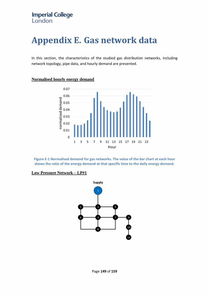
Page 149 of 159
Appendix E. Gas network data
In this section, the characteristics of the studied gas distribution networks, including
network topology, pipe data, and hourly demand are presented.
Normalised hourly energy demand
Figure E-1 Normalised demand for gas networks. The value of the bar chart at each hour shows the ratio of the energy demand at that specific time to the daily energy demand.
Low Pressure Network – LP#1
1
25 4
36 7 9
10
11
8
Supply

Page 150 of 159
Pipe
No.
From
Node
To
Node
Length
(m)
Diameter
(mm)
1 1 2 50 0.16
2 2 3 500 0.16
3 2 4 500 0.11
4 2 5 500 0.11
5 3 6 600 0.11
6 3 7 600 0.11
7 3 8 500 0.11
8 5 6 600 0.08
9 4 7 600 0.08
10 6 8 780 0.08
11 7 8 780 0.08
12 7 9 200 0.08
13 9 10 200 0.08
14 10 11 200 0.08
Node
No.
Gas peak
demand (cm)
1 0
2 3462.0797
3 3046.6667
4 2769.5723
5 3600.5507
6 2492.6303
7 692.355
8 3254.297
9 761.66667
10 657.77533
11 484.57233
Low Pressure Network – LP#2
Network characteristic for LP#2:
Pipe
No.
From
Node
To
Node
Length
(m)
Diameter
(mm)
Pipe
No.
From
Node
To
Node
Length
(m)
Diameter
(mm)
874 5321
75
64
26
57
17
52
45
22
31
67
99
98
84
88
74
93
94
97
201918
272625
352
352
5655
636261
727170
9291
87
112
24
2
5453
46
47
33 34
23
35
6968
60
8685
9089
6
32
100 101
102 103
104
105
106 107
108109 110 111
113
114115
Supply 1
Supply 2

Page 151 of 159
Pipe
No.
From
Node
To
Node
Length
(m)
Diameter
(mm)
Pipe
No.
From
Node
To
Node
Length
(m)
Diameter
(mm)
1 53 54 240 150 55 103 105 492 150
2 54 55 456 150 56 105 106 230 150
3 55 56 702 150 57 106 107 289 150
4 56 57 653 150 58 107 108 276 150
5 60 54 43 100 59 109 110 322 80
6 60 61 446 150 60 110 111 220 80
7 60 69 66 100 61 112 113 184 300
8 61 55 75 150 62 115 114 164 100
9 61 62 709 150 63 1 2 184 300
10 61 70 266 200 64 1 17 52 150
11 62 63 656 150 65 2 3 308 300
12 62 71 302 100 66 3 4 817 300
13 63 64 33 200 67 4 5 922 300
14 63 74 322 200 68 5 6 102 400
15 64 57 59 200 69 5 7 394 300
16 64 75 315 100 70 7 8 62 300
17 67 68 256 150 71 8 51 886 200
18 67 84 230 150 72 17 18 554 150
19 68 69 249 100 73 17 22 72 150
20 68 89 502 100 74 18 19 256 125
21 69 85 308 100 75 19 20 525 150
22 70 71 656 80 76 19 36 722 100
23 70 87 154 200 77 20 25 256 300
24 71 72 459 80 78 22 31 230 150
25 71 92 328 100 79 22 33 574 100
26 72 74 259 80 80 23 34 187 100
27 74 75 23 150 81 24 25 289 100
28 74 93 305 200 82 25 26 623 100
29 84 88 207 150 83 25 36 299 300
30 85 86 197 80 84 26 27 525 100
31 85 90 318 100 85 26 38 308 100
32 86 87 230 80 86 27 39 285 100
33 86 111 879 80 87 31 32 226 80
34 87 91 174 200 88 31 45 322 150

Page 152 of 159
Pipe
No.
From
Node
To
Node
Length
(m)
Diameter
(mm)
Pipe
No.
From
Node
To
Node
Length
(m)
Diameter
(mm)
35 88 89 361 80 89 33 54 531 100
36 88 98 331 100 90 33 34 256 100
37 89 90 197 80 91 34 35 594 100
38 89 100 315 100 92 36 37 66 300
39 90 101 302 100 93 37 38 614 100
40 91 92 732 100 94 37 48 269 300
41 91 102 390 200 95 38 39 535 80
42 92 93 728 100 96 38 49 295 100
43 92 103 341 100 97 39 50 285 100
44 93 94 52 150 98 45 52 302 150
45 94 97 367 150 99 46 47 200 100
46 97 107 118 150 100 47 53 361 100
47 98 99 295 80 101 47 33 256 100
48 98 100 240 100 102 48 55 276 300
49 100 101 220 100 103 48 49 689 80
50 101 110 312 100 104 49 56 269 100
51 102 103 827 150 105 49 50 551 80
52 102 113 499 300 106 50 51 46 80
53 102 114 400 150 107 51 57 230 200
54 103 104 295 100 108 52 53 295 150
Gas demand for LP#2:
Node
No.
Gas peak
demand (cm)
Node
No.
Gas peak
demand (cm)
Node
No.
Gas peak
demand (cm)
1 7.16415 45 8.041971 85 6.45623
2 4.927123 46 4.672272 86 38.14273
3 6.512864 47 12.88414 87 23.67284
4 2.803363 48 34.43323 88 12.54434
5 6.597814 49 35.70748 89 5.125341
7 6.597814 50 23.24809 90 4.417421
8 0.991088 51 0.991088 91 21.71899
17 3.5396 52 8.49504 92 21.94552
18 4.629797 53 8.183555 93 19.42532
19 20.18988 54 17.92453 94 30.63878
20 18.85899 55 26.22136 97 44.08926
22 7.362368 56 24.23918 98 52.86747

Page 153 of 159
Node
No.
Gas peak
demand (cm)
Node
No.
Gas peak
demand (cm)
Node
No.
Gas peak
demand (cm)
23 4.87049 57 10.25068 99 25.00373
24 6.45623 60 7.16415 100 8.041971
25 38.14273 61 4.927123 101 4.672272
26 23.67284 62 6.512864 102 12.88414
27 12.54434 63 2.803363 103 34.43323
31 5.125341 64 6.597814 104 35.70748
32 4.417421 67 6.597814 105 23.24809
33 21.71899 68 0.991088 106 0.991088
34 21.94552 69 3.5396 108 8.49504
35 19.42532 70 4.629797 109 8.183555
36 30.63878 71 20.18988 110 17.92453
37 44.08926 72 18.85899 111 26.22136
38 52.86747 74 7.362368 114 24.23918
39 25.00373 75 4.87049 115 10.25068
Medium Pressure Network - MP
20
21
23
22
9
368634
24
19
1211107
43
2
33
29
26
251814132
15
16
5235
13
31 30
28
27
17
Supply

Page 154 of 159
Network characteristic for MP:
Pipe
No.
From
Node
To
Node
Length
(m)
Diameter
(mm)
Pipe
No.
From
Node
To
Node
Length
(m)
Diameter
(mm)
1 1 26 1706 50 21 12 9 213 40
2 1 32 525 65 22 14 1 180 65
3 2 5 66 32 23 14 27 1378 50
4 2 35 66 32 24 15 4 148 40
5 3 5 197 32 25 15 16 197 32
6 3 15 131 40 26 16 17 197 40
7 4 19 213 40 27 16 18 197 32
8 5 14 295 32 28 18 14 197 65
9 6 34 492 200 29 18 25 394 65
10 7 10 197 32 30 19 20 164 40
11 7 33 482 50 31 19 24 180 25
12 8 6 1247 200 32 20 21 197 32
13 8 9 230 65 33 21 23 66 50
14 8 36 7546 200 34 26 28 427 40
15 9 22 148 40 35 26 29 295 40
16 10 2 591 32 36 29 30 164 40
17 10 11 197 32 37 29 31 98 40
18 11 3 541 32 38 33 1 469 50
19 11 12 279 32 39 35 13 164 32
20 12 4 525 40
Gas demand for MP:
Node
No.
Gas Peak
Load (cm)
Node
No.
Gas Peak
Load (cm)
1 40.36985 18 22.2301
2 20.46993 19 16.80999
3 27.25011 20 14.87
4 25.61 22 5.499972
5 16.80999 23 5.499972
7 21.35002 24 5.499972
9 8.350058 25 39.65994
10 27.25011 26 23.06007
11 27.25011 27 26.03985
12 23.92005 28 5.499972
13 5.499972 29 14.87
14 42.70995 30 5.620035
15 8.350058 31 5.620035
16 8.350058 32 150
17 12.84988 34 5199.996

Page 155 of 159
High Pressure Network – HP#1
A high-pressure gas distribution test network with supply pressure between 38 to 70 bar
(NTS offtake) was simulated. The peak energy demand for this system is 104.5 GWh per
day (equivalent to 9.5 million cubic meter of natural gas). The energy demand is
distributed uniformly across the nodes.
Network characteristic for HP#1
Pipe
No.
From
Node
To
Node
Lengt
h (m)
Diamete
r (mm)
1 1 3 8558 1193
2 3 5 9559 1193
3 5 7 12035 1038
4 7 9 50 590
5 7 11 7197 590
6 11 13 6726 590
7 13 15 4739 590
8 15 17 2495 590
9 17 19 4996 590
10 19 21 4844 590
11 21 23 50 590
12 21 25 4439 590
13 25 27 3774 590
14 27 29 2509 590
1
3
5
7
9
111315
17
19
2123
25
27
29
Supply
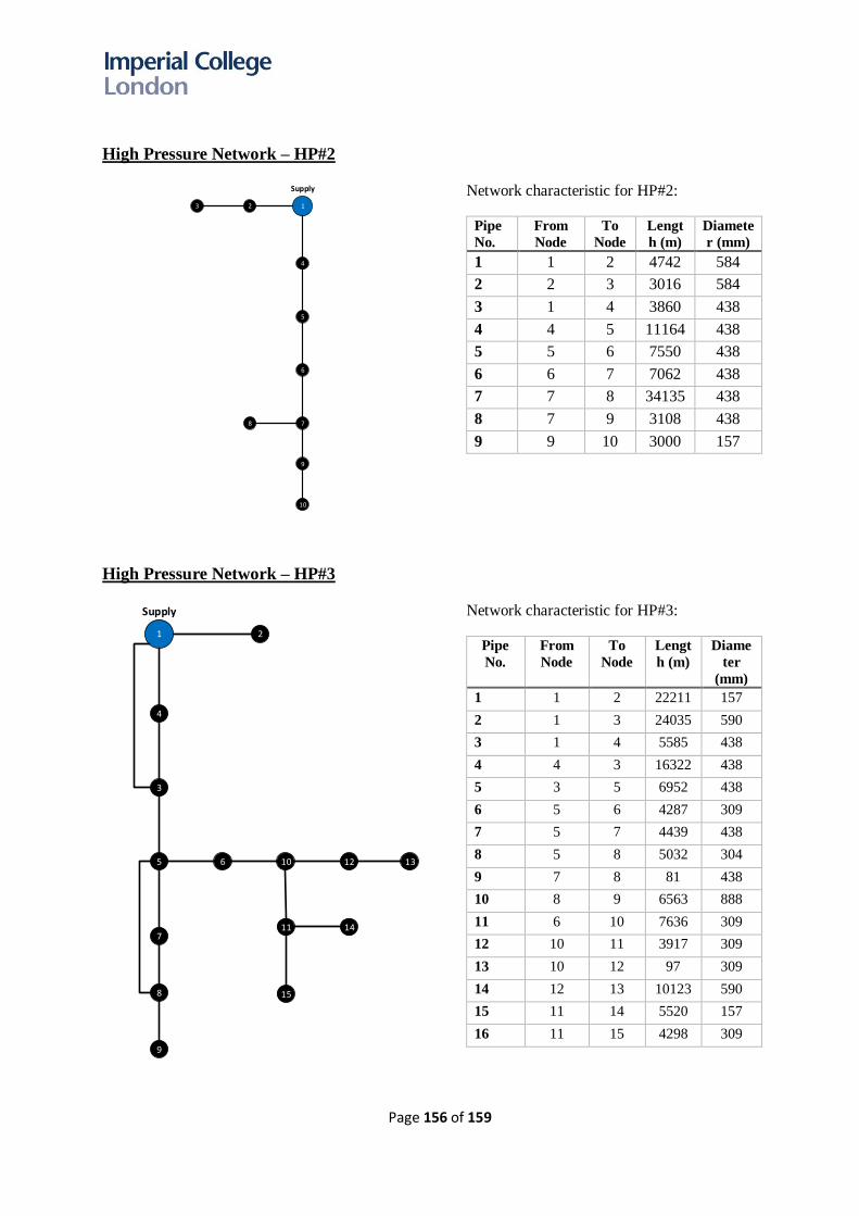
Page 156 of 159
High Pressure Network – HP#2
Network characteristic for HP#2:
Pipe
No. From
Node To
Node Lengt
h (m) Diamete
r (mm)
1 1 2 4742 584
2 2 3 3016 584
3 1 4 3860 438
4 4 5 11164 438
5 5 6 7550 438
6 6 7 7062 438
7 7 8 34135 438
8 7 9 3108 438
9 9 10 3000 157
High Pressure Network – HP#3
Network characteristic for HP#3:
Pipe
No.
From
Node
To
Node
Lengt
h (m)
Diame
ter
(mm)
1 1 2 22211 157
2 1 3 24035 590
3 1 4 5585 438
4 4 3 16322 438
5 3 5 6952 438
6 5 6 4287 309
7 5 7 4439 438
8 5 8 5032 304
9 7 8 81 438
10 8 9 6563 888
11 6 10 7636 309
12 10 11 3917 309
13 10 12 97 309
14 12 13 10123 590
15 11 14 5520 157
16 11 15 4298 309
1
4
5
6
7
23
8
9
10
Supply
1
4
3
5
7
2
8
9
6 10
11
12 13
14
15
Supply

Page 157 of 159
Hydrogen storage capacity for balancing
Table E-1 shows the hydrogen storage capacity requirement in different region.
Table E-1 Hydrogen storage capacity required in different region across GB
Region H2 storage (GWh) - Low H2 storage (GWh) - High
Eastern 9.9 25.8
East Midlands 12.2 32.2
North East 7.7 20.2
North 2.9 8.2
North Thames 22.0 47.9
North West 17.6 45.5
Scotland 10.1 26.1
South East 22.7 57.2
South 7.2 19.3
South West 1.7 4.8
West Midlands 11.7 30.6
North Wales 0.6 1.6
South Wales 5.2 13.7
Total 131.4 333.1

Page 158 of 159
Appendix F. GB system model
The studies were carried out on a simplified 14-regions GB model resembling the GB distribution
network operators’ operating regions as shown in Figure F-1.
Figure F-1 A 14-regions GB model
The regions are interconnected by electricity and hydrogen transmission networks; the network
capacities are optimised by the model. The interconnection capacities between GB and Ireland, and
between GB and the continental Europe (Norway, France, Belgium, and Netherlands) are modelled
and optimised.
In each region, the networks are grouped into two different types, (i) high demand density and (ii)
low demand density systems. The annual heat demand (TWhth) is given in Table F.1. The capacity of
electrical distribution networks is optimised considering the local installed capacity of distributed
generation and also the optimised electricity demand profiles depending on the level of demand
flexibility used in the study.
Region Regionname
1 NorthScotland
2 SouthScotland
3 NorthWestEngland
4 NorthEastEngland
5
NorthWales,Merseysideand
Cheshire
6 Yorkshire
7 SouthWales
8 WestMidlands
9 EastMidlands
10 SouthWestEngland
11 SouthernEngland
12 London
13 EastEngland
14 SouthEastEngland

Page 159 of 159
Table F-1 Annual heat demand (TWh) across different regions
Region
Districts with high demand
density [urban] (TWh)
Districts with low demand
density [non-urban]
(TWh)
North Scotland 3 19
South Scotland 11 33
North West England 17 32
North East England 16 19
North Wales, Merseyside and Cheshire 6 25
Yorkshire 24 21
South Wales 9 14
West Midlands 20 32
East Midlands 21 32
South West England 10 24
Southern England 28 38
London 55 0
East England 22 53
South East England 15 33