analysis of harmonic reduction methods for …
TRANSCRIPT

Technical Sciences, 2020, 23(1), 5–23
doi: 10.31648/ts.5331
Correspondence: Szymon Racewicz, Katedra Mechatroniki i Edukacji Techniczno-Informa-tycznej, Wydział Nauk Technicznych, Uniwersytet Warmińsko-Mazurski, ul. Oczapowskiego 11, 10-719 Olsztyn, e-mail: [email protected]
ANALYSIS OF HARMONIC REDUCTION METHODS FOR TRANSFORMER SUBSTATIONS
Szymon Racewicz1, Mateusz Rokicki2
1ORCID: 0000-0002-3426-9767 Department of Mechatronics and Technical-Computer Sciences Education
University of Warmia and Mazury in Olsztyn2ORCID: 0000-0002-7604-8612
Maintenance DepartmentMichelin Polska SA, Olsztyn
Received 7 October 2019, accepted 20 February 2020, available online 9 March 2020.
K e y w o r d s: harmonic reduction; active filters; THD coefficient.
A b s t r a c t
This article presents an analysis of harmonic levels and methods for reducing harmonics in one of Michelin transformer substations. The electrical network in the substation consists of two transformers (1.6 MVA and 2.0 MVA) supplying a production line composed of several electrical devices using DC and AC motors. The influence of harmonic levels on substation operation was investigated by measuring the current and the load factors of the powered machines as well as coefficients THDu, THDi, Du and Di with the use of the Fluke 435II 3-phase energy quality analyz-er and the PEL103 network parameter recorder. Based on the results of the measurements, four harmonic reduction methods (passive filters, active filters, 12-pulse rectifier and the Active Front End system) were proposed and tested in the study. The electrical network of the substation was modeled using Emerson Harmonics Estimator software. A financial analysis of potential invest-ments was performed to select the optimal solution.
Technical Sciences 23(1) 2020
6 Szymon Racewicz, Mateusz Rokicki
Introduction
Higher harmonics of voltages and currents are among the main disturbances occurring in electric power systems. They appear in power grids due to the constantly increasing number of electrical equipment with nonlinear characteristics and at the same time due to the decreasing tendency of resistive devices share (Hanzelka 2001). Even if a unit power of the device installed in the network is small like for example for lighting installations, the considering number of such devices can significantly decrease energy quality in the network by increasing the content of higher harmonics. Then low quality of the energy influences on other equipment present in the network (GirGis et al. 1992). For the last few decades the knowledge about the problems associated with harmonics has been improved significantly (Mazin et al. 2011, Hu et al. 2018, sHarMa et al. 2016, Motta, Faúndes 2016, ViVek et al. 2016). Nevertheless, it allows us only to reduce the threats rather than to completely eliminate them.
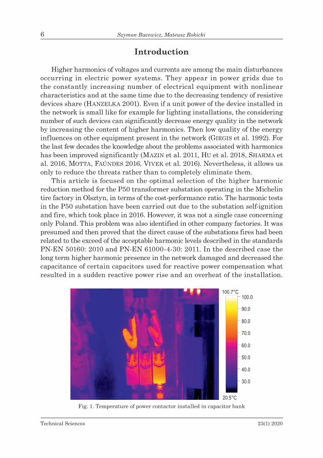
This article is focused on the optimal selection of the higher harmonic reduction method for the P50 transformer substation operating in the Michelin tire factory in Olsztyn, in terms of the cost-performance ratio. The harmonic tests in the P50 substation have been carried out due to the substation self-ignition and fire, which took place in 2016. However, it was not a single case concerning only Poland. This problem was also identified in other company factories. It was presumed and then proved that the direct cause of the substations fires had been related to the exceed of the acceptable harmonic levels described in the standards PN-EN 50160: 2010 and PN-EN 61000-4-30: 2011. In the described case the long term higher harmonic presence in the network damaged and decreased the capacitance of certain capacitors used for reactive power compensation what resulted in a sudden reactive power rise and an overheat of the installation.
Fig. 1. Temperature of power contactor installed in capacitor bank
Technical Sciences 23(1) 2020
Analysis of Harmonic Reduction Methods for Transformer Substations 7
This hypothesis was also confirmed by the thermovision measurements which showed the increased current consumption flowing through the power contactors installed in the capacitor bank (Fig. 1). In order to improve the safety and to guarantee the substation reliability the level of higher harmonics present in the substation network was reduced significantly. For this purpose and in order to choose the best filtration method a number of measurements and tests have been carried out.
The efficiency of the filtration method has been evaluated by measuring certain coefficients like: the ratio of the nth harmonic to the fundamental harmonics for voltage and current (Du, Di) given by equations 1 and 2 as well as the quotient of the harmonic effective value to the effective value of the fundamental harmonic for voltage and current (THDu, THDi) given by equations 3 and 4 (arrillaGa et al. 1985, Horska et al. 2014).
𝐷𝐷𝑢𝑢(𝑛𝑛) =𝑈𝑈𝑟𝑟𝑟𝑟𝑟𝑟(𝑛𝑛)𝑈𝑈𝑟𝑟𝑟𝑟𝑟𝑟(1)
∙ 100% (1)
𝐷𝐷𝑖𝑖(𝑛𝑛) =𝐼𝐼𝑟𝑟𝑟𝑟𝑟𝑟(𝑛𝑛)𝐼𝐼𝑟𝑟𝑟𝑟𝑟𝑟(1)
∙ 100% (2)
THD𝑢𝑢 =√∑ 𝑈𝑈(𝑛𝑛)2∞
𝑛𝑛=2
𝑈𝑈(1)∙ 100% (3)
THD𝑖𝑖 =√∑ 𝐼𝐼(𝑛𝑛)2∞
𝑛𝑛=2
𝐼𝐼(1)∙ 100% (4)
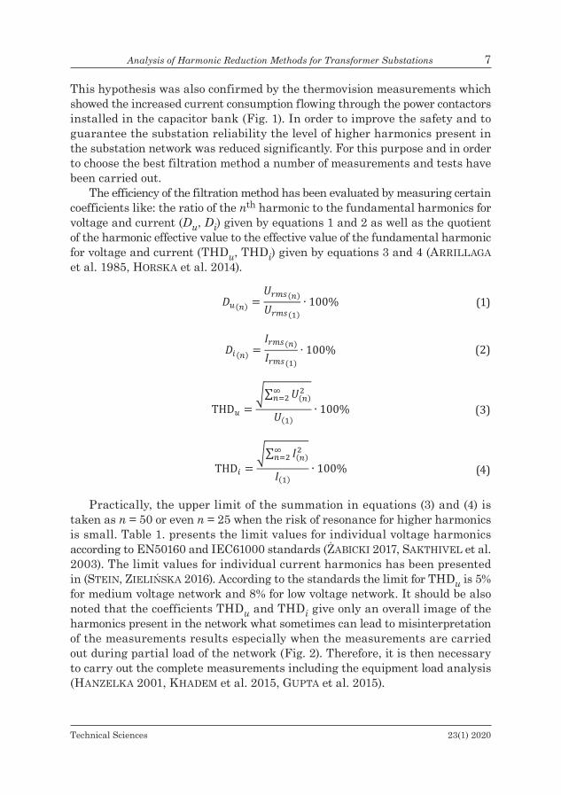
Practically, the upper limit of the summation in equations (3) and (4) is taken as n = 50 or even n = 25 when the risk of resonance for higher harmonics is small. Table 1. presents the limit values for individual voltage harmonics according to EN50160 and IEC61000 standards (Żabicki 2017, saktHiVel et al. 2003). The limit values for individual current harmonics has been presented in (Stein, ZielińSka 2016). According to the standards the limit for THDu is 5% for medium voltage network and 8% for low voltage network. It should be also noted that the coefficients THDu and THDi give only an overall image of the harmonics present in the network what sometimes can lead to misinterpretation of the measurements results especially when the measurements are carried out during partial load of the network (Fig. 2). Therefore, it is then necessary to carry out the complete measurements including the equipment load analysis (Hanzelka 2001, kHadeM et al. 2015, Gupta et al. 2015).
Technical Sciences 23(1) 2020
8 Szymon Racewicz, Mateusz Rokicki
Table 1Limit values for individual voltage harmonics according
to EN50160 and IEC61000 standards
Odd harmonicsEven harmonics
Not a multiplicity of 3 multiplicity of 3Order amplitude [%] order amplitude [%] order amplitude [%]
5 6 3 5 2 27 5 9 1.5 4 1
11 3.5 15 0.5 6 0.513 3 21 0.5 8 0.517 2 – – 10 0.519 1.5 – – 12 0.523 1.5 – – 14 0.525 1.5 – – 16 0.5– – – – 18 0.5– – – – 20 0.5– – – – 22 0.5– – – – 24 0.5
Fig. 2. Variation of THDi value for different loads

Technical Sciences 23(1) 2020
Analysis of Harmonic Reduction Methods for Transformer Substations 9
Research object
The P50 substation consists of two transformers (TR1 and TR2) which powers are 2 MVA and 1.6 MVA respectively. It supplies the extrusion line P01 which serves to mix three components to obtain a product for a tire tread as well as to reuse its own returns. The P01 line consists of: three extruders cold fed (supplied by the TR1) and heating rolling mill, plasticizer and extruder NAR1200 (supplied by the TR2). All of devices are driven by DC and AC motors of 2184 kW total power. The P01 line has been designed for continuous operation. Schematic of the P50 substation electrical network has been shown in Figure 3. In the network schematic the two capacitor banks C1 and C2 as well as other electric receivers (lighting, control systems, etc.) modeled by L1 and L2 have been shown.
Fig. 3. Schematic of P50 transformer substation electrical network
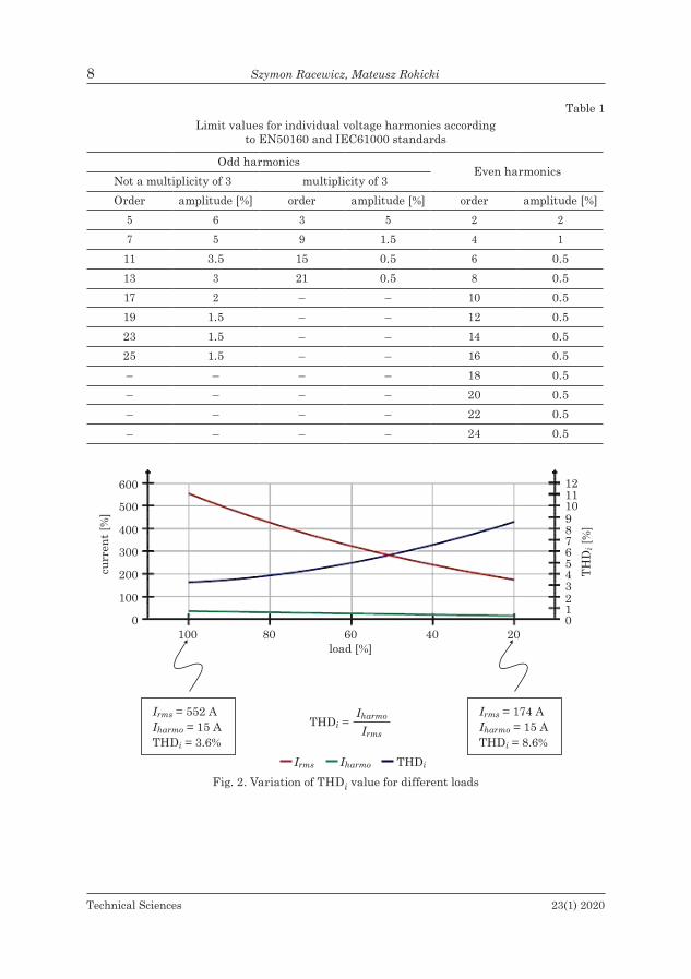
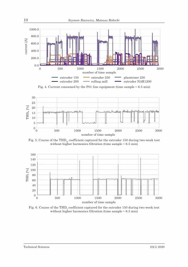
Figure 4 shows currents consumed by the equipment installed in the P01 extrusion line. Taking into consideration the nominal values of the equipment motor currents one can calculate that the average load factor of the devices is not exceeding 50%. The load factor is closely related to the assortment currently produced by the extrusion line what in consequence causes variation of the THD coefficients. Therefore, the continuous monitoring of higher harmonic present in electric network is necessary.
The following figures (Figs. 5, 6, 7, 8) show courses of the coefficients THDu, and THDi captured for the extruder 150 during the test which has been carried out for two weeks as well as the values of the coefficients Du, and Di for sub-sequent odd harmonics up to 30th picked for one of the stable operating state.
Technical Sciences 23(1) 2020
10 Szymon Racewicz, Mateusz Rokicki
Fig. 4. Current consumed by the P01 line equipment (time sample ≈ 6.5 min)
Fig. 5. Course of the THDu coefficient captured for the extruder 150 during two-week test without higher harmonics filtration (time sample ≈ 6.5 min)
Fig. 6. Course of the THDi coefficient captured for the extruder 150 during two-week test without higher harmonics filtration (time sample ≈ 6.5 min)
Technical Sciences 23(1) 2020
Analysis of Harmonic Reduction Methods for Transformer Substations 11
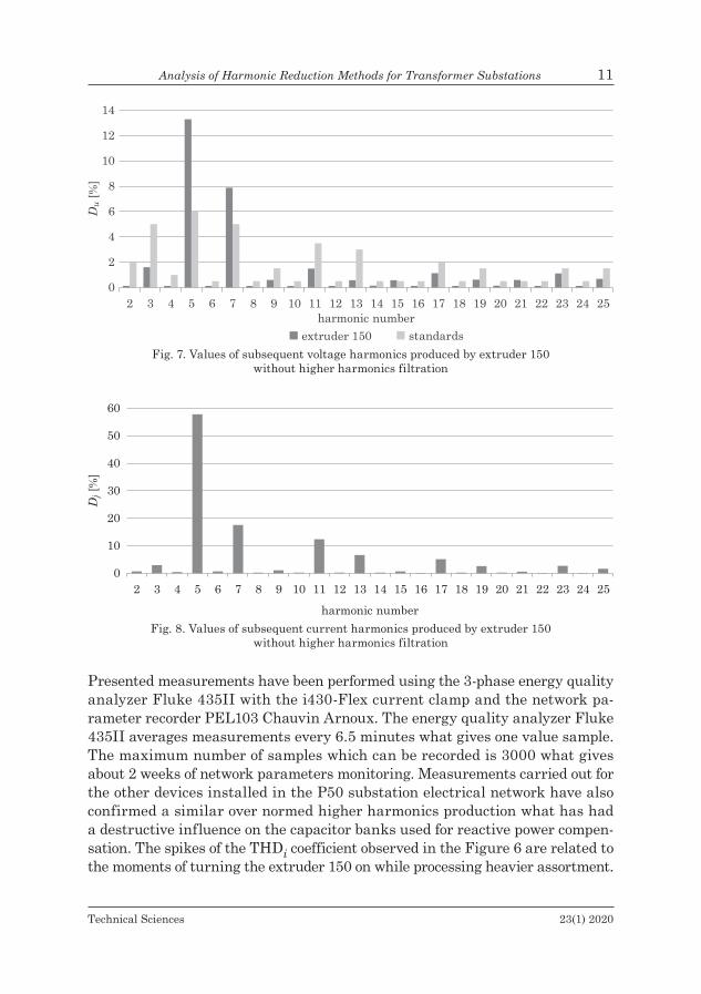
Presented measurements have been performed using the 3-phase energy quality analyzer Fluke 435II with the i430-Flex current clamp and the network pa-rameter recorder PEL103 Chauvin Arnoux. The energy quality analyzer Fluke 435II averages measurements every 6.5 minutes what gives one value sample. The maximum number of samples which can be recorded is 3000 what gives about 2 weeks of network parameters monitoring. Measurements carried out for the other devices installed in the P50 substation electrical network have also confirmed a similar over normed higher harmonics production what has had a destructive influence on the capacitor banks used for reactive power compen-sation. The spikes of the THDi coefficient observed in the Figure 6 are related to the moments of turning the extruder 150 on while processing heavier assortment.
Fig. 7. Values of subsequent voltage harmonics produced by extruder 150 without higher harmonics filtration
Fig. 8. Values of subsequent current harmonics produced by extruder 150 without higher harmonics filtration
Technical Sciences 23(1) 2020
12 Szymon Racewicz, Mateusz Rokicki
Simulation results
The evaluation of filtration quality for four types of solutions (passive filters, active filters, 12-pulse rectifiers, AFE) has been carried out using the predefined models available in the Emerson Harmonics Estimator simulation software. The measured machines loads have been introduced into the Emerson software individually for each machine as a percentage of nominal machine load. Simulation results have served to predict the potential level of higher harmonics presented at the secondary side of the transformers for different methods of harmonics reduction and to compare the methods with each other.
Passive filters
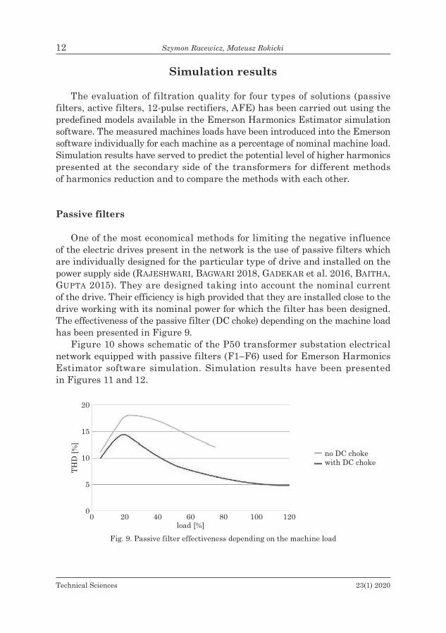
One of the most economical methods for limiting the negative influence of the electric drives present in the network is the use of passive filters which are individually designed for the particular type of drive and installed on the power supply side (RajeShwaRi, bagwaRi 2018, gadekaR et al. 2016, baitha, Gupta 2015). They are designed taking into account the nominal current of the drive. Their efficiency is high provided that they are installed close to the drive working with its nominal power for which the filter has been designed. The effectiveness of the passive filter (DC choke) depending on the machine load has been presented in Figure 9.
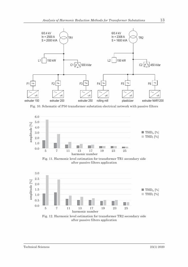
Figure 10 shows schematic of the P50 transformer substation electrical network equipped with passive filters (F1–F6) used for Emerson Harmonics Estimator software simulation. Simulation results have been presented in Figures 11 and 12.
Fig. 9. Passive filter effectiveness depending on the machine load
Technical Sciences 23(1) 2020
Analysis of Harmonic Reduction Methods for Transformer Substations 13
Fig. 10. Schematic of P50 transformer substation electrical network with passive filters
Fig. 11. Harmonic level estimation for transformer TR1 secondary side after passive filters application
Fig. 12. Harmonic level estimation for transformer TR2 secondary side after passive filters application
Technical Sciences 23(1) 2020
14 Szymon Racewicz, Mateusz Rokicki
Active filters
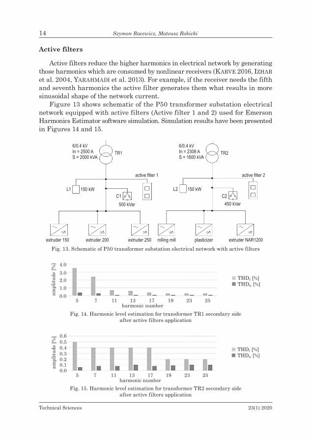
Active filters reduce the higher harmonics in electrical network by generating those harmonics which are consumed by nonlinear receivers (karVe 2016, izHar et al. 2004, YaraHMadi et al. 2013). For example, if the receiver needs the fifth and seventh harmonics the active filter generates them what results in more sinusoidal shape of the network current.
Figure 13 shows schematic of the P50 transformer substation electrical network equipped with active filters (Active filter 1 and 2) used for Emerson Harmonics Estimator software simulation. Simulation results have been presented in Figures 14 and 15.
Fig. 13. Schematic of P50 transformer substation electrical network with active filters
Fig. 14. Harmonic level estimation for transformer TR1 secondary side after active filters application
Fig. 15. Harmonic level estimation for transformer TR2 secondary side after active filters application
Technical Sciences 23(1) 2020
Analysis of Harmonic Reduction Methods for Transformer Substations 15
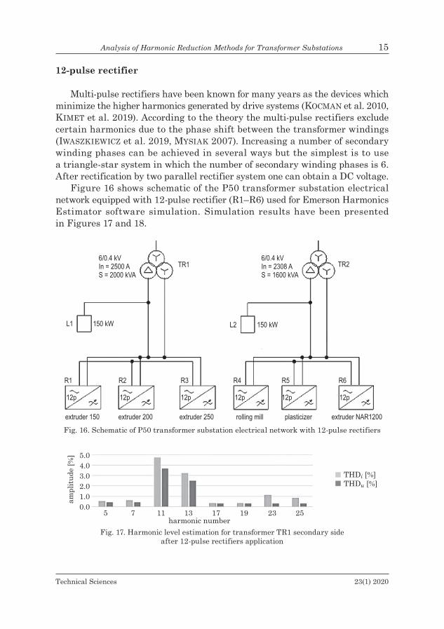
12-pulse rectifier
Multi-pulse rectifiers have been known for many years as the devices which minimize the higher harmonics generated by drive systems (kocman et al. 2010, kiMet et al. 2019). According to the theory the multi-pulse rectifiers exclude certain harmonics due to the phase shift between the transformer windings (iwaSZkiewicZ et al. 2019, MYsiak 2007). Increasing a number of secondary winding phases can be achieved in several ways but the simplest is to use a triangle-star system in which the number of secondary winding phases is 6. After rectification by two parallel rectifier system one can obtain a DC voltage.
Figure 16 shows schematic of the P50 transformer substation electrical network equipped with 12-pulse rectifier (R1–R6) used for Emerson Harmonics Estimator software simulation. Simulation results have been presented in Figures 17 and 18.
Fig. 16. Schematic of P50 transformer substation electrical network with 12-pulse rectifiers
Fig. 17. Harmonic level estimation for transformer TR1 secondary side after 12-pulse rectifiers application
Technical Sciences 23(1) 2020
16 Szymon Racewicz, Mateusz Rokicki
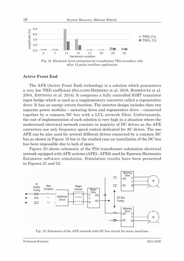
Fig. 18. Harmonic level estimation for transformer TR2 secondary side after 12-pulse rectifiers application
Active Front End
The AFE (Active Front End) technology is a solution which guarantees a very low THD coefficient (salGado-Herrera et al. 2018, RodRígueZ et al. 2004, espinosa et al. 2014). It comprises a fully controlled IGBT transistor input bridge which is used as a supplementary converter called a regenerative drive. It has an energy return function. The inverter design includes then two separate power modules – motoring drive and regenerative drive – connected together by a common DC bus with a LCL network filter. Unfortunately, the cost of implementation of such solution is very high in a situation where the modernized electrical network consists in majority of DC drives as the AFE converters use only frequency speed control dedicated for AC drives. The one AFE can be also used for several different drives connected by a common DC bus as shown in Figure 19 but in the studied case an installation of the DC bus has been impossible due to lack of space.
Figure 20 shows schematic of the P50 transformer substation electrical network equipped with AFE systems (AFE1–AFE6) used for Emerson Harmonics Estimator software simulation. Simulation results have been presented in Figures 21 and 22.
Fig. 19. Schematic of the AFE network with DC bus circuit for many machines

Technical Sciences 23(1) 2020
Analysis of Harmonic Reduction Methods for Transformer Substations 17
Fig. 20. Schematic of P50 transformer substation electrical network with AFE system
Fig. 21. Harmonic level estimation for transformer TR1 secondary side after AFE system application
Fig. 22. Harmonic level estimation for transformer TR2 secondary side after AFE system application

Technical Sciences 23(1) 2020
18 Szymon Racewicz, Mateusz Rokicki
Discussion of the results
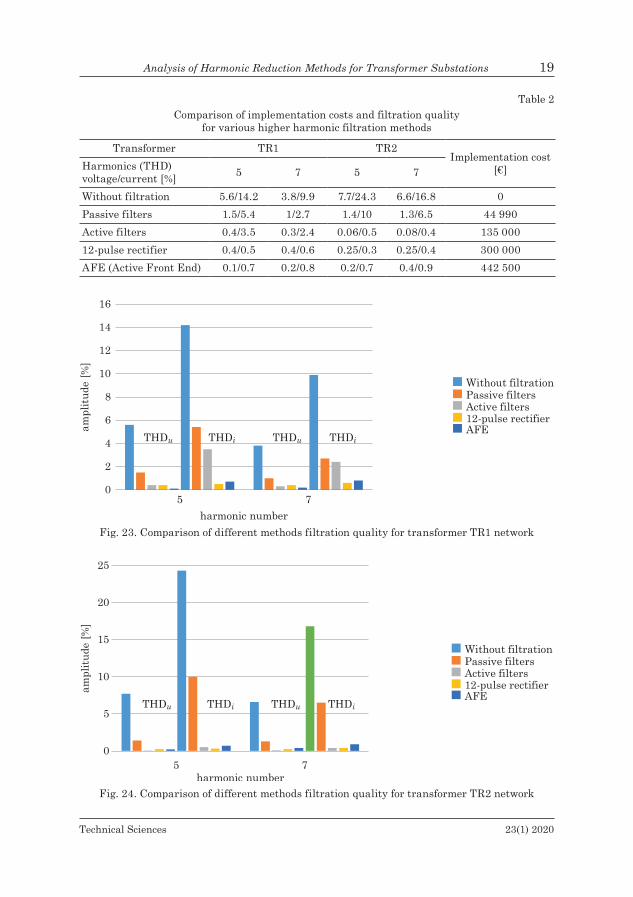
Comparing the simulation results one can observe that the best quality of higher harmonic filtration is realized by the AFE system where all higher harmonics values have been reduced to below 1% (Figs. 21, 22). It is also the more expensive solution valued at 442 500 € what is mainly associated with the need to replace the DC motors by the AC motors. The second more expensive filtration method is the use of the 12-pulse rectifiers which also need some equipment replacement. It is valued at 300 000 € because of the need to replace the two of transformers (TR1 and TR2) by the ones with two secondary windings connected in star and triangle. The filtration quality is acceptable for the fifth and the seventh harmonics. Nevertheless, for the studied case the simulations have revealed also the presence of the eleventh and the thirteenth harmonics what is not favorable for the condition of the network (Figs. 17, 18). The least expensive solution for the higher harmonic filtration is the use of passive filters valued at 44 990 €. The main disadvantage of this method is related to an inability to adapt to the changing network conditions present in the P01 extrusion production line. Moreover, the filtration quality is several times lower than for the other methods (Figs. 11, 12). The last studied method, i.e. active filters ensures effective higher harmonics reduction (Figs. 14, 15) at a relatively low cost of investment (135 000 €).
All of above mentioned methods with their implementation cost and the filtration quality analysis for the fifth and the seventh harmonics have been collected in the Table 2 and compared in the Figures 23 and 24. The filtration quality has been presented in the Table 2 as the THD coefficient values respectively for voltage and current.
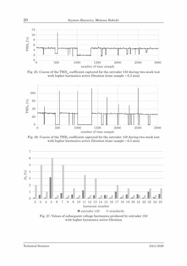
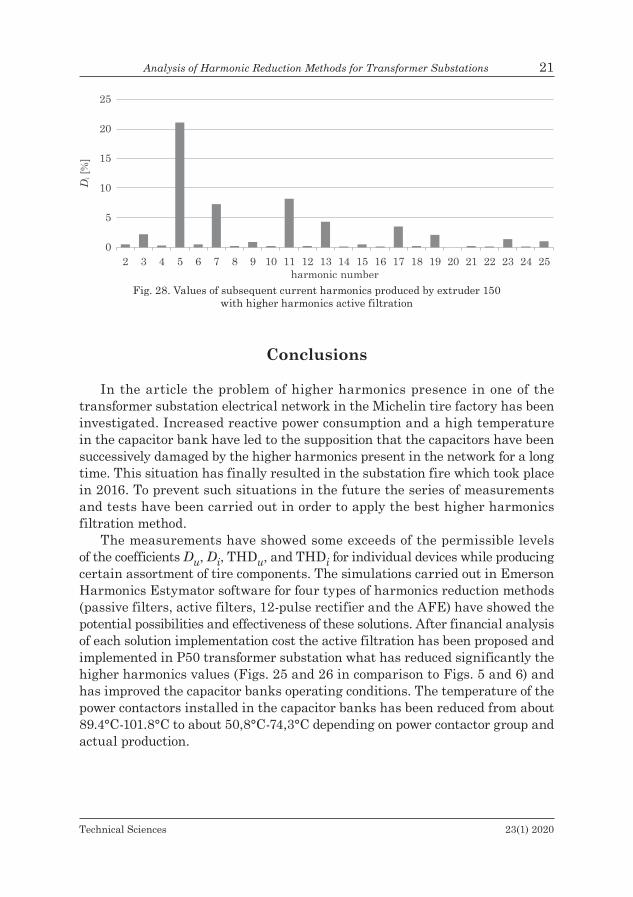
Finally, after above mentioned analysis the active filter technology has been chosen for the P01 extrusion line. More precisely, the active filters AccuSine PCS – Power Correction system – Model CE54 – Sizes 300A have been installed in the TR1 and the TR2 networks. More detailed information about the filters can be found in the technical documentation (AccuSine ® Power Correction… 2012). The active filter implementation has resulted in considerable higher harmonic reduction. Figures 25, 26, 27 and 28 show the measurements results of the THDu, THDi, Du and Di coefficients captured for the extruder 150 after the filters installation. In comparison to the Figures 5, 6, 7 and 8 one can observe the THDu reduction from more than 15% to about 5% and the THDi reduction from more than 60% to about 30%. Regarding Du and Di coefficients, particularly important is reduction of the 5th and the 7th harmonics which exceeded standard limits before filtration implementation.
Technical Sciences 23(1) 2020
Analysis of Harmonic Reduction Methods for Transformer Substations 19
Table 2Comparison of implementation costs and filtration quality
for various higher harmonic filtration methods
Transformer TR1 TR2Implementation cost
[€]Harmonics (THD) voltage/current [%] 5 7 5 7
Without filtration 5.6/14.2 3.8/9.9 7.7/24.3 6.6/16.8 0 Passive filters 1.5/5.4 1/2.7 1.4/10 1.3/6.5 44 990 Active filters 0.4/3.5 0.3/2.4 0.06/0.5 0.08/0.4 135 000 12-pulse rectifier 0.4/0.5 0.4/0.6 0.25/0.3 0.25/0.4 300 000 AFE (Active Front End) 0.1/0.7 0.2/0.8 0.2/0.7 0.4/0.9 442 500
Fig. 23. Comparison of different methods filtration quality for transformer TR1 network
Fig. 24. Comparison of different methods filtration quality for transformer TR2 network
Technical Sciences 23(1) 2020
20 Szymon Racewicz, Mateusz Rokicki
Fig. 25. Course of the THDu coefficient captured for the extruder 150 during two-week test with higher harmonics active filtration (time sample ≈ 6.5 min)
Fig. 26. Course of the THDi coefficient captured for the extruder 150 during two-week test with higher harmonics active filtration (time sample ≈ 6.5 min)
Fig. 27. Values of subsequent voltage harmonics produced by extruder 150 with higher harmonics active filtration
Technical Sciences 23(1) 2020
Analysis of Harmonic Reduction Methods for Transformer Substations 21
Fig. 28. Values of subsequent current harmonics produced by extruder 150 with higher harmonics active filtration
Conclusions
In the article the problem of higher harmonics presence in one of the transformer substation electrical network in the Michelin tire factory has been investigated. Increased reactive power consumption and a high temperature in the capacitor bank have led to the supposition that the capacitors have been successively damaged by the higher harmonics present in the network for a long time. This situation has finally resulted in the substation fire which took place in 2016. To prevent such situations in the future the series of measurements and tests have been carried out in order to apply the best higher harmonics filtration method.
The measurements have showed some exceeds of the permissible levels of the coefficients Du, Di, THDu, and THDi for individual devices while producing certain assortment of tire components. The simulations carried out in Emerson Harmonics Estymator software for four types of harmonics reduction methods (passive filters, active filters, 12-pulse rectifier and the AFE) have showed the potential possibilities and effectiveness of these solutions. After financial analysis of each solution implementation cost the active filtration has been proposed and implemented in P50 transformer substation what has reduced significantly the higher harmonics values (Figs. 25 and 26 in comparison to Figs. 5 and 6) and has improved the capacitor banks operating conditions. The temperature of the power contactors installed in the capacitor banks has been reduced from about 89.4°C-101.8°C to about 50,8°C-74,3°C depending on power contactor group and actual production.
Technical Sciences 23(1) 2020
22 Szymon Racewicz, Mateusz Rokicki
References
arrillaGa J., bRadley d.a., bodgeR P.S. 1985. Power System Harmonics. John Wiley. https://books.google.pl/books/about/Power_system_harmonics.html?id=st1SAAAAMAAJ&redir_esc=y.
baitha a., guPta n. 2015. A Comparative Analysis of Passive Filters for Power Quality Improve-ment. Proceedings of IEEE International Conference on Technological Advancements in Power and Energy, TAP Energy, p. 327–332. Institute of Electrical and Electronics Engineers Inc. https://doi.org/10.1109/TAPENERGY.2015.7229640.
espinosa e., espinoza J., roHten J., raMirez r., reYes M., Munoz J., Melin p. 2014. An Effi-ciency Comparison between a 18 Pulses Diode Rectifier and a Multi-Cell AFE Rectifier Operating with FCS – MPC. IECON Proceedings (Industrial Electronics Conference), p. 1214–1220. Insti-tute of Electrical and Electronics Engineers Inc. https://doi.org/10.1109/IECON.2014.7048657.
Gadekar s., kulkarni n., MHetre s., kulkarni H.H. 2016. Design and Development of Passive Filter and Comparative Study of Simulation Results of Passive and Active Filter. International Conference on Energy Systems and Applications, ICESA, p. 324–328. Institute of Electrical and Electronics Engineers Inc. https://doi.org/10.1109/ICESA.2015.7503364.
giRgiS a.a., nimS j.w., jacomino j., dalton j.g., biShoP a. 1992. Effect of Voltage Harmonics on the Operation of Solid-State Relays in Industrial Applications. IEEE Transactions on Industry Applications, 28(5): 1166–1173. https://doi.org/10.1109/28.158844.
guPta c., VaRShney a., VeRma n., Shukla S. 2015. THD Analysis of Eleven Level Cascaded H-Bridge Multilevel Inverter with Different Types of Load Using in Drives Applications. Proceed-ings – 2015 2nd IEEE International Conference on Advances in Computing and Communication Engineering, ICACCE, p. 355–359. Institute of Electrical and Electronics Engineers Inc. https://doi.org/10.1109/ICACCE.2015.61.
Hanzelka z. 2001. Jakość energii elektrycznej. Część 4. Wyższe harmoniczne napięć i prądów. Ele-ktroinstalator, 12: 1–31. http://twelvee.com.pl/pdf/Hanzelka/cz_4_pelna.pdf (access: 27.05.2019).
Horska J., Maslan s., streit J., sira M. 2014. A Validation of a THD Measurement Equip-ment with a 24-Bit Digitizer. CPEM Digest (Conference on Precision Electromagnetic Measure-ments), p. 502–503. Institute of Electrical and Electronics Engineers Inc. https://doi.org/10.1109/CPEM.2014.6898479.
hu h., Shao y., tang l., ma j., he Z., gao S. 2018. Overview of Harmonic and Resonance in Railway Electrification Systems. IEEE Transactions on Industry Applications, 54(5): 5227–5245. https://doi.org/10.1109/TIA.2018.2813967.
iwaSZkiewicZ j., muc a., mySiak P. 2019. A 12-Pulse Rectifier Using Coupled Reactors for Sup-plying Three-Inverters. Renewable Energy and Power Quality Journal, 17: 589–592. https://doi.org/10.24084/repqj17.382.
iZhaR m., hadZeR c.m., SyafRudin m., taib S., idRiS S. 2004. An Analysis and Design of a Star Delta Transformer in Series with Active Power Filter for Current Harmonics Reduction. National Power and Energy Conference, PECon 2004 – Proceedings, p. 94–97. https://doi.org/10.1109/PECON.2004.1461623.
karVe s. 2016. Jakość energii. Harmoniczne filtry aktywne. Europejski Instytut Miedzi – Leonardo Energy, Wrocław. https://leonardo-energy.pl/wp-content/uploads/2016/05/EIM01210-Harmon-iczne-filtry-aktywne.pdf.
khadem S.k., baSu m., keRRigan R., baSu b. 2015. Power Quality Analysis of Energy Efficient Harmonic Loads. Institute of Electrical and Electronics Engineers (IEEE) , 470–471. https://doi.org/10.1109/icce-berlin.2014.7034333.
kiM J., lai J.s., liu X. 2019. Analysis of Harmonic Cancellation Performance of a Shunt Phase-Shift Transformer Rectifier. In 2018 IEEE 4th Southern Power Electronics Conference, SPEC 2018. Institute of Electrical and Electronics Engineers Inc. https://doi.org/10.1109/SPEC.2018.8635850.

Technical Sciences 23(1) 2020
Analysis of Harmonic Reduction Methods for Transformer Substations 23
kocman S., kolaR V., Vo t.t. 2010. Elimination of Harmonics Using Multi-Pulse Rectifiers. In ICHQP 2010 – 14th International Conference on Harmonics and Quality of Power. https://doi.org/10.1109/ICHQP.2010.5625408.
maZin h.e., Xu w., huang b. 2011. Determining the Harmonic Impacts of Multiple Harmonic-Pro-ducing Loads. IEEE Transactions on Power Delivery, 26(2): 1187–1195. https://doi.org/10.1109/TPWRD.2010.2093544.
Motta l., Faúndes n. 2016. Active / Passive Harmonic Filters: Applications, Challenges & Trends. Proceedings of International Conference on Harmonics and Quality of Power, ICHQP, p. 657–662. IEEE Computer Society. https://doi.org/10.1109/ICHQP.2016.7783319.
MYsiak p. 2007. A 24-Pulse Diode Rectifier with Coupled Three-Phase Reactor. Journal of the Chi-nese Institute of Engineers, Transactions of the Chinese Institute of Engineers,Series A/Chung-Kuo Kung Ch’eng Hsuch K’an, 30(7): 1197–1212. https://doi.org/10.1080/02533839.2007.9671347.
RajeShwaRi, bagwaRi a. 2018. Voltage Harmonic Reduction Using Passive Filter Shunt Passive-Ac-tive Filters for Non-Linear Load. Proceedings 7th International Conference on Communication Systems and Network Technologies, CSNT, p. 131–36. Institute of Electrical and Electronics Engineers Inc. https://doi.org/10.1109/CSNT.2017.8418524.
RodRígueZ j., Pontt j., hueRta R., newman P. 2004. 24-Pulse Active Front End Rectifier with Low Switching Frequency. PESC Record – IEEE Annual Power Electronics Specialists Conference, 5: 3517–3523. https://doi.org/10.1109/PESC.2004.1355097.
saktHiVel k.n., das s.k., kini k.r. 2003. Importance of Quality AC Power Distribution and Understanding of EMC Standards IEC 61000-3-2, IEC 61000-3-3 and IEC 61000-3-11. Proceedings of the International Conference on Electromagnetic Interference and Compatibility, p. 423–30. Institute of Electrical and Electronics Engineers Inc. https://doi.org/10.1109/ICEMIC.2003.238094.
Salgado-heRReRa n.m., anaya-laRa o., camPoS-gaona d., medina-RioS a., taPia-SancheZ R., RodRigueZ-RodRigueZ j.R. 2018. Active Front-End Converter Applied for the THD Reduction in Power Systems. IEEE Power and Energy Society General Meeting. IEEE Computer Society. https://doi.org/10.1109/PESGM.2018.8586414.
AccuSine ® Power Correction System (PCS) Models: CE30 & CE54 Sizes: 50A, 100A, 300A Instruc-tion Bulletin. 2012. Schneider Electric.
sHarMa H., rYlander M., dorr d. 2016. Grid Impacts Due to Increased Penetration of Newer Harmonic Sources. IEEE Transactions on Industry Applications, 52(1): 99–104. https://doi.org/10.1109/TIA.2015.2464175.
Stein Z., ZielińSka m. 2016. Analiza harmonicznych w prądzie zasilającym wybrane urządzenia średniej mocy. Electrical Engineering, 86: 213–19.
ViVek g., naiR m.d., baRai m. 2016. Online Reduction of Fifth and Seventh Harmonics in Single Phase Quasi Square Wave Inverters. 12th IEEE International Conference Electronics, Energy, Environment, Communication, Computer, Control (E3-C3), INDICON 2015. Institute of Elec-trical and Electronics Engineers Inc. https://doi.org/10.1109/INDICON.2015.7443721.
YaraHMadi s., Markade G.a., soltani J. 2013. Current Harmonics Reduction of Non-Linear Load by Using Active Power Filter Based on Improved Sliding Mode Control. PEDSTC 2013 – 4th Annual International Power Electronics, Drive Systems and Technologies Conference, p. 524–528. https://doi.org/10.1109/PEDSTC.2013.6506763.
Żabicki d. 2017. Jakość energii elektrycznej według normy PN-EN 50160. Elektroinstalator, 6.
