analysis of pump-turbine s instability and reverse
TRANSCRIPT

4-th International Meeting on
Cavitation and Dynamic Problems in Hydraulic Machinery and Systems,
October, 26-28, 2011, Belgrade, Serbia
Analysis of Pump-Turbine “S” Instability and Reverse
Waterhammer Incidents in Hydropower Systems
Stanislav Pejovic1, Qin Fen Zhang
2, Bryan Karney
3, Aleksandar Gajic
4
1Prof. Emeritus, 300 Webb Drive #1411, Mississauga, Ontario, Canada L5B 3W3. [email protected],
Website: www.StanPejovic.com 2Oak Ridge National Laboratory, USA. [email protected]
3Civil Eng. Dept, University of Toronto, Canada
4Faculty of Mechanical Engineering, University of Belgrade, Serbia
Abstract
Hydraulic systems continually experience dynamic transients or oscillations which threaten the hydroelectric plant
from extreme water hammer pressures or resonance. In particular, the minimum pressure variations downstream of the
turbine runner during the load rejection or other events may cause dangerous water column separation and subsequent
rejoinder. Water column separation can be easily observed from the measurements of site transient tests, and has indeed
caused serious historical damages to the machine and water conveyance system. Several technical issues regarding water
column separation in draft tubes, including “S” instability of turbine characteristic curves, numerical instability and
uncertainty of computer programs, are discussed here through case studies and available model and site test data.
Catastrophic accidents experienced at a Kaplan turbine and in a long tailrace tunnel project, as well as other troubles
detected in a more timely fashion, are revisited in order to demonstrate the severity of reverse water hammer. However,
as there is no simple design solutions for such complex systems, this paper emphasizes that the design of hydraulic
systems is always difficult, difficulties that are compounded when the phenomena in question are non-linear (water
hammer), dynamic (involving wave interaction and complex devices of turbines, controls, and electrical systems), and
non-monotonic (severity of response is seldom simply connected to severity of load as with vibrations and resonance,
and the complexity of transient loads), and thus may lead to high economic and safety challenges and consequences.
Keywords: Pump-turbine; Load rejection; Transients; Reverse waterhammer; “S” instability; Water column separation.
1. Introduction
The design, construction and operation of a hydropower plant involve numerous challenges in environmental and hydrologic
assessments, engineering planning and design, financing with far-sighted political perspective, demanding construction and
supervision, painstaking commissioning and troubleshooting, and meticulous operation and control. Tens of thousands of details
must be well conceived, accurately executed, and carefully coordinated for a project to achieve economic, social, technical and
environmental success. Overlooking or poorly integrating such details can cause great complications. One such vital detail is
hydraulic design of tailrace tunnels, for which the paper overviews a few particular hydro systems and provides background on the
observed water column separation and rejoinder phenomena. There tends to be a bias favoring the analysis of upstream hydraulic
components including the turbine, while less attention is paid to the downstream water passage, often treating the design of draft
tube and tailrace as mere afterthoughts. Yet, many important, and potentially destructive, hydraulic phenomena occur in the draft
tube, its extension, and/or the pressurized tailrace tunnel, especially if the tailrace is long. The term “tailrace tunnel” in this context
refers to a pressurized conduit. Reflections on actual events in such systems lead to vital lessons for future safe and effective
design. In hydropower plants with long tailrace tunnels, the minimum pressure at the downstream of turbine runner, resulted from
load rejection or other transient events, can seriously damage or impair both the turbine assembly and the water conveyance
system.
Reliable knowledge of all loads acting upon a system is the key to safe hydraulic system design. The most dangerous stresses
are those provoked by pressure surge and vibrations; and the worst case is the occurrence of resonances. Maximum pressure
during transient events, such as those associated with rapid closing and opening of wicket gates, can break equipment while events
like earthquakes can destroy pipelines, valves or other components and may even result in the loss of life. Sound design of a new
plant is impossible without a complete analysis of transient events. Transient analysis also helps to prevent resonance in existing

DOI: to be inserted by the publisher
4th
IAHR Meeting on Cavitation and Dynamic Problems in Hydraulic Machinery and Systems, October 26-28, 2011, Belgrade
2/16
plants and thus increases the reliability of plants and reduces their operating and maintenance costs.
The costs associated with cavitation, transient conditions, vibrations and stress analysis for mini, small and big hydroelectric
plants are often quite comparable in absolute values; thus the relative cost, as a fraction of the total investment, is obviously much
greater for smaller plants. Such analysis costs in large plants usually entail less than one percent of the total, whereas these costs
can be a sizable fraction of the overall expenses in some small plants. Though suffering from the same problems as the large ones,
there is a dangerous though understandable tendency to simplify analysis and review process for reducing the design costs of small
plants. The net result is that there tends to be higher risks in smaller plants [26].
Pumped-storages (and hydro storages) are of paramount importance as they are the most reliable and affordable energy
storages for accommodating intermittent renewable generators in the power grid, also providing ancillary services as readily
adjustable stand-by and running reserve for nuclear and other thermal generators. However, large hydro facilities require a large
amount of capital investment, so their design, construction and operation needs to be well conceived, executed and coordinated, if
they are to achieve the safe and economical operation. The challenges of high-head typical of pump-storage further complicate
system design. This fact, together with cost stress on the construction, equipment and labor, justifies the need for more rational
design of new pumped storage plants. That is, the system components should be strained as close to the allowable limits as
possible, without endangering the safety.
For a low-specific-speed (high-head) reversible pump-turbine, owing to their “S” shaped turbine characteristics, the operations
are unstable near or at runaway conditions, leading to oscillations characterized by large pressure fluctuations and transients as the
system passes through the unstable dangerous zone [10, 11, 13, 32, 33]. The analysis of transients is rather a complex and time
consuming task, each case introducing some new problems. Our experience on “S” form instability and hydraulic resonance,
gathered from pumped-storage plant Bajina Basta in Serbia (previously, Yugoslavia), the plant endangered by hydraulic transients,
is reviewed in this paper. Transient analyses were exercised at all design levels of Bajina Basta plant by both the design team (led
by the first author) and the manufacturer (Toshiba). The “S” type instability was discovered and first publicly reported during
1974-1976 [32], while the numerical instability of computer program in the “S” zone is discussed for the first time in this paper.
In order to avoid the danger of water column separation and consequent reverse waterhammer, the minimum pressure in any
conduit (tunnel, penstock, pipeline), as a design criterion, should not fall below 50 kPa (0.5 bar), even temporarily [1, 17, 23, 24].
This minimum pressure must be the instantaneous value during a transient event and at the highest position of waterway, typically
at the runner outlet or at the upper limit of draft tube lining. Since pressure transducers only can be attached to the wall of draft
tube, and since the water in the draft tube is usually in rotary motion, the measured pressure is actually the maximum value for a
given cross-section; the pressure in the vortex core, by contrast, is likely at absolute vapor pressure or at the air release pressure of
the dissolved air, or slightly above this if air injected [7, 14, 31]. Therefore, the measured pressures cannot be used directly as a
design criterion. Some manufacturers have empirical pressure and velocity distribution data for their machines [12], and others
have measured data from model turbine draft tubes [7]. All the data for each machine must be carefully evaluated because the
similarity laws do not strictly apply to two-phase flows [8, 2121].
In practice, the lowest transient pressures are typically approximated using one-dimensional waterhammer theory and transient
modeling, which only represents the “cross-sectional average” pressures which are usually higher than those found in the vortex
core and lower than those measured at the wall of draft tube cone. In addition, the numerical analysis results could be uncertain
and inaccurate around the unstable zones of turbine characteristics, so the numerical analysis must be thoroughly performed and
experimentally confirmed. A larger safety margin is prudent for the minimum pressures in the draft tube, particularly given the
complexity and uncertainty of these transient flows, as well the lack of an applicable similarity law. Moreover, the speed
increment of the runner, in runaway condition, is crucial since the voids formed by the centrifugal force of the high-speed rotating
water can be large; the pressure rise caused by even slow accelerations/decelerations of the tailrace water may have a strong
influence on void collapse.
2. Transient analyses of Bajina Basta Pump-Turbine System
2.1 Four quadrant characteristic curves and “S” instability of reversible pump-turbines
High-head reversible pump-turbines with low-specific-speed have an unusual characteristic in turbine operating modes: unlike
typical behavior, beyond the runaway zone, any decrease in speed reduces the discharge. In an -
diagram partial load curves
for a pump-turbine are markedly "S‟ shaped, as shown in Error! Reference source not found.. In this runaway zone the flow
through the runner is highly complex: the water near the bend separates, flowing toward the turbine, while the water near the
crown goes opposite way - towards the wicket gates. The net discharge might be either negative (turbine) or positive (pump).
These operating modes are, naturally accompanied with violent vibrations and highly developed cavitation [3, 20 and 33].
Nevertheless, such machines are needed and rapidly developed towards higher head and greater unit power. The pump-storage
power plant "Bajina Basta" ( ) has such low specific speed pump-turbines. Is specific speed nq = 27 ( √ ⁄⁄ ), having a
typical “S” type unstable characteristic as all other high-head pumps and pump-turbines. The numerical simulations exhibited
intensive instability and resonance, though the accuracy of analysis is reasonably low.
To discuss the pump-turbine model characteristics, the unit speed, unit flow and unit hydraulic torque are defined as:
√ ;
√ ;
Mh is the hydraulic torque. In the “S” zone three (dimensionless) discharge values of
⁄ two
negative and one positive, correspond to one value of
⁄ also three (dimensionless) torques of
⁄ , two positive and
DOI: to be inserted by the publisher
4th
IAHR Meeting on Cavitation and Dynamic Problems in Hydraulic Machinery and Systems, October 26-28, 2011, Belgrade
3/16
one negative, correspond to one value of
⁄ . Such multi-valued nature would result in a difficulty in application of these
curves to transient simulation. To overcome the challenge, various representations have been used in numerical modeling and each
presents certain merits and limitations (Chaudhry, 1987 and Pejovic, et al., 1983). In Suter parameters, the head WH and torque WB
characteristics are defined as single-valued in the entire area covered by the polar angle )/(tan 1 vx (Suter, 1966; Thorley, et
al., 1966):
RRRR
BHn
n
T
T
Q
Qv
H
Hh
vSIGNxW
v
hhSIGNxW
,,, here, ; )()( ; )()(
2222
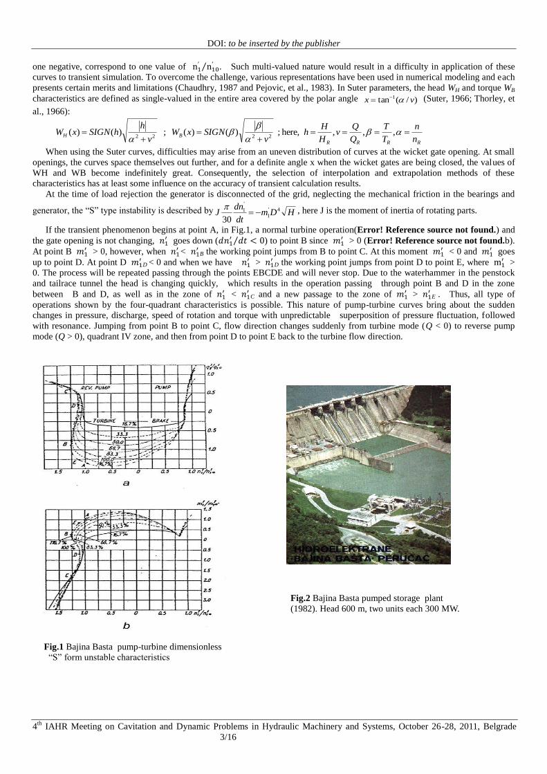
When using the Suter curves, difficulties may arise from an uneven distribution of curves at the wicket gate opening. At small
openings, the curves space themselves out further, and for a definite angle x when the wicket gates are being closed, the values of
WH and WB become indefinitely great. Consequently, the selection of interpolation and extrapolation methods of these
characteristics has at least some influence on the accuracy of transient calculation results.
At the time of load rejection the generator is disconnected of the grid, neglecting the mechanical friction in the bearings and
generator, the “S” type instability is described by HDmdt
dnJ 4'
1
'
1
30
, here J is the moment of inertia of rotating parts.
If the transient phenomenon begins at point A, in Fig.1, a normal turbine operation(Error! Reference source not found.) and
the gate opening is not changing, goes down (
⁄ ) to point B since > 0 (Error! Reference source not found.b).
At point B > 0, however, when
<
B the working point jumps from B to point C. At this moment < 0 and
goes
up to point D. At point D
D < 0 and when we have >
D the working point jumps from point D to point E, where
>
0. The process will be repeated passing through the points EBCDE and will never stop. Due to the waterhammer in the penstock
and tailrace tunnel the head is changing quickly, which results in the operation passing through point B and D in the zone
between B and D, as well as in the zone of <
C and a new passage to the zone of
>
E . Thus, all type of
operations shown by the four-quadrant characteristics is possible. This nature of pump-turbine curves bring about the sudden
changes in pressure, discharge, speed of rotation and torque with unpredictable superposition of pressure fluctuation, followed
with resonance. Jumping from point B to point C, flow direction changes suddenly from turbine mode (Q < 0) to reverse pump
mode (Q > 0), quadrant IV zone, and then from point D to point E back to the turbine flow direction.
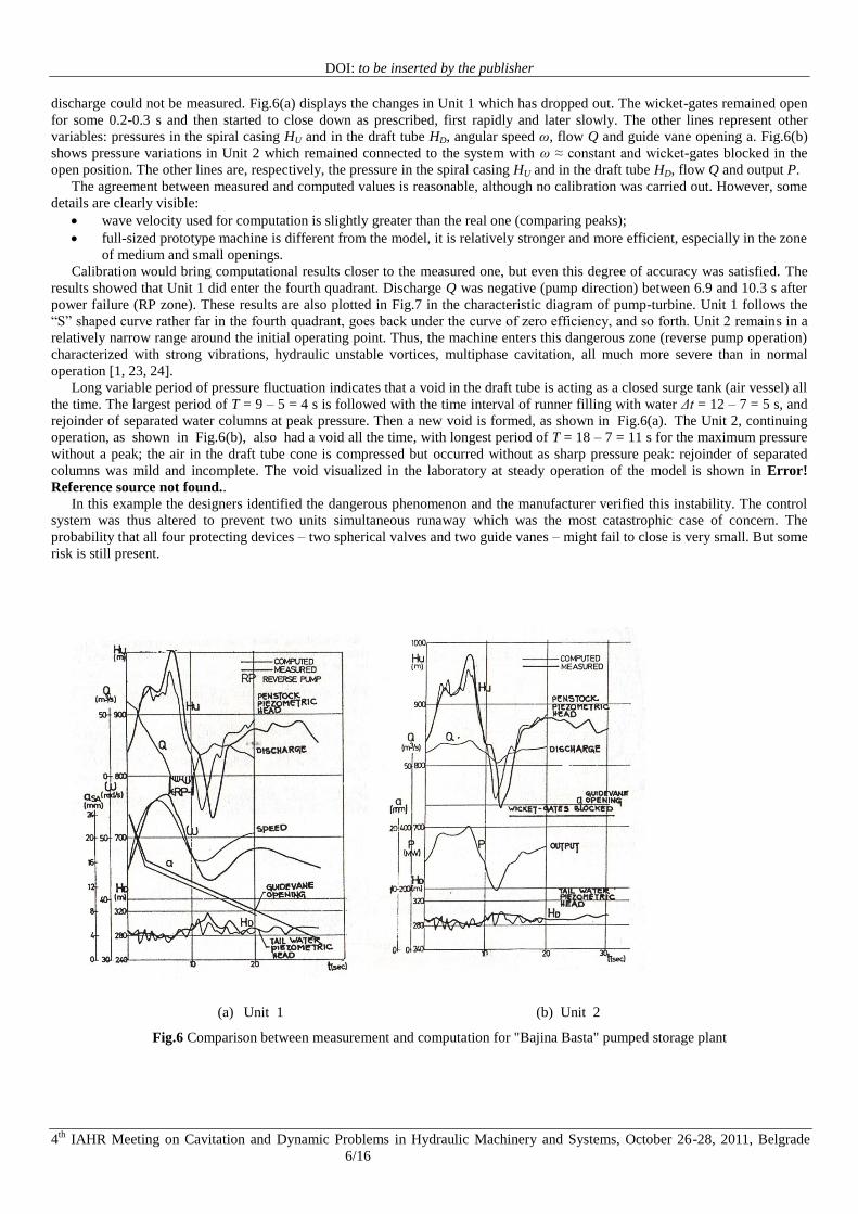
Fig.2 Bajina Basta pumped storage plant
(1982). Head 600 m, two units each 300 MW.
Fig.1 Bajina Basta pump-turbine dimensionless
“S” form unstable characteristics

DOI: to be inserted by the publisher
4th
IAHR Meeting on Cavitation and Dynamic Problems in Hydraulic Machinery and Systems, October 26-28, 2011, Belgrade
4/16
2.2 Computer Program and Mathematical Model
The discussed computer program was first developed in 1968 on an Elliote 803b papertape computer. The programs were
subsequently transformed into FORTRAN, being gradually improved to be able to handle any system configuration, simulate
waterhammer and hydraulic oscillations [33, 22]. A realistic application case of this computer program is for "Bajina Basta"
pumped-storage hydroelectric plant (Fig.2). This plant is equipped with two 300 MW units, sharing a 8000 m long tunnel, a
common 1200 m penstock, and a 300 m tailrace tunnel, as shown schematically in Error! Reference source not found.. The units
are submerged 54 m below the tail water level to protect the system from cavitation and water column separation. Two identical
pump-turbines, each developing 315 MW in turbine operation, with 600 m of net head, are installed in the power house. The
maximum pump input is 310 MW for 50.8 m3/s flow. The maximum pumping head is over 620 m.
The mathematical model represents the plant by a system of nodes and links. The nodes are as follows: storage basin (node
1), surge tank (2), penstock valves (3), upper (6) and lower (11) branching, pump-turbines (9 and 10), ball valves (7 and 8), lower
reservoirs (13). Nodes (4), (5) and (12) are connection of pipes of different diameters.
Fig.3 Pumped storage plant “Bajina Basta”
2.3 Two Units Load Rejection
Simultaneous full load rejection of two turbine units with wicket-gates blocked in an open position (Fig.4) would cause
dangerous pressure surges. It was clear that the machines tended to enter the reverse pump zone (so called "fourth quadrant"),
alternatively, due to the slightly asymmetric branch pipes. The associated fluctuations in discharge were remarkable, with changes
from the pump to turbine mode occurring in a matter of seconds as result of the instability of the “S” shaped pump-turbine
characteristics in the runaway zone. These phenomena were described by Pejovic at a1. [32] and Gajic [6] obtained similar results
using another computer program. These results were initially viewed as so dramatic because only a few believed that a machine
could enter the fourth quadrant; so some kind of verification was needed (1975). When the plant was finally completed (1982) the
field tests fully confirmed the earlier computation results.
If the two units experience runaway simultaneously, the flow in the loop would go through phase shift; one machine would
experience turbine flow and the other in the pump zone (see solid and dashed curves in Fig.4, respectively). The hydraulic torque
acts to accelerate the shaft rotation of one unit and decelerate the other one. The shorter the pipes in the loop (the less inertia of
water in them), the more violent the pressure surges; dangerous reverse waterhammer could damage the hydraulic machines and
waterways and then flooding would be inevitable.
The peaks of pressure fluctuations exceeded 900 m, the design penstock pressure head. Therefore, the governing and protective
system had been changed to prevent parallel runaway of both units to minimize the risk of a catastrophic accident. The problem
was solved by ensuring that any of the four protective devices respond to all critical transients [20]. Though it is highly improbable
that all four closing devices jointly fail, careful maintenance must ensure their continuous operation.
The design team of this power plant carefully analyzed hydraulic transients and discovered a dangerous “S” form instability,
which was published for the first time by Pejovic et al. 1976 [32]. However, the water column separation during runaway
remained unnoticed as extremely dangerous by the design team (Pejovic was one member of the team), neither had it been
indicated by turbine manufacturers nor other experts involved in the design and construction of the plant. Fortunately, the problem
was resolved by preventing the turbine running through the unstable “S” zone of transient operation.

DOI: to be inserted by the publisher
4th
IAHR Meeting on Cavitation and Dynamic Problems in Hydraulic Machinery and Systems, October 26-28, 2011, Belgrade
5/16
Fig.4 Waterhammer calculation; two units‟ runaway simultaneously; guide vanes and inlet penstock valves are open; both
pump-turbines run at full runaway; calculated zero pressure in the turbine draft tubes means water column separation
2.4 Load Rejection of One Unit
The response of load rejection from one unit and its resulting runaway are shown in Fig.5 [32]. The amplitude of pressure
fluctuation in the draft tube, H”, is as high as ± 3 bar, at the inlet, H‟, up to ± 18 bar, and the discharge is jumping from turbine to
pump direction [32].
Fig.5 Bajina Basta one unit load rejection
2.5 Comparing Simulation with Experiment
Field tests have been carried out several times in "Bajina Basta" plant both by the manufacturer and the asset owner. Several
situations were tested, and various physical variables were measured and recorded. One such an event was taking place in
February 1983, the testing procedure was:
both units 1 & 2 operated as turbines, developing 298 MW each;
Unit 1 dropped out and its wicket gates closed down rapidly;
Unit 2 remained operational in spite of violent pressure surges.
A couple of multi-channel acquisition systems were used to record pressures in the spiral casings above and under the runners
and in the draft tubes, as well as to record wicket-gates servo strokes, generators‟ currents and rotating speeds of the shafts. The
DOI: to be inserted by the publisher
4th
IAHR Meeting on Cavitation and Dynamic Problems in Hydraulic Machinery and Systems, October 26-28, 2011, Belgrade
6/16
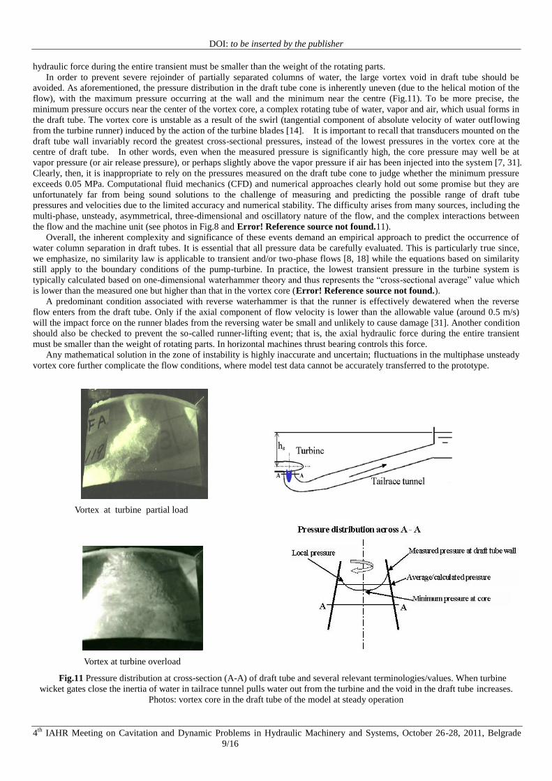
discharge could not be measured. Fig.6(a) displays the changes in Unit 1 which has dropped out. The wicket-gates remained open
for some 0.2-0.3 s and then started to close down as prescribed, first rapidly and later slowly. The other lines represent other
variables: pressures in the spiral casing HU and in the draft tube HD, angular speed ω, flow Q and guide vane opening a. Fig.6(b)
shows pressure variations in Unit 2 which remained connected to the system with ω ≈ constant and wicket-gates blocked in the
open position. The other lines are, respectively, the pressure in the spiral casing HU and in the draft tube HD, flow Q and output P.
The agreement between measured and computed values is reasonable, although no calibration was carried out. However, some
details are clearly visible:
wave velocity used for computation is slightly greater than the real one (comparing peaks);
full-sized prototype machine is different from the model, it is relatively stronger and more efficient, especially in the zone
of medium and small openings.
Calibration would bring computational results closer to the measured one, but even this degree of accuracy was satisfied. The
results showed that Unit 1 did enter the fourth quadrant. Discharge Q was negative (pump direction) between 6.9 and 10.3 s after
power failure (RP zone). These results are also plotted in Fig.7 in the characteristic diagram of pump-turbine. Unit 1 follows the
“S” shaped curve rather far in the fourth quadrant, goes back under the curve of zero efficiency, and so forth. Unit 2 remains in a
relatively narrow range around the initial operating point. Thus, the machine enters this dangerous zone (reverse pump operation)
characterized with strong vibrations, hydraulic unstable vortices, multiphase cavitation, all much more severe than in normal
operation [1, 23, 24].
Long variable period of pressure fluctuation indicates that a void in the draft tube is acting as a closed surge tank (air vessel) all
the time. The largest period of T = 9 – 5 = 4 s is followed with the time interval of runner filling with water Δt = 12 – 7 = 5 s, and
rejoinder of separated water columns at peak pressure. Then a new void is formed, as shown in Fig.6(a). The Unit 2, continuing
operation, as shown in Fig.6(b), also had a void all the time, with longest period of T = 18 – 7 = 11 s for the maximum pressure
without a peak; the air in the draft tube cone is compressed but occurred without as sharp pressure peak: rejoinder of separated
columns was mild and incomplete. The void visualized in the laboratory at steady operation of the model is shown in Error!
Reference source not found..
In this example the designers identified the dangerous phenomenon and the manufacturer verified this instability. The control
system was thus altered to prevent two units simultaneous runaway which was the most catastrophic case of concern. The
probability that all four protecting devices – two spherical valves and two guide vanes – might fail to close is very small. But some
risk is still present.
(a) Unit 1 (b) Unit 2
Fig.6 Comparison between measurement and computation for "Bajina Basta" pumped storage plant

DOI: to be inserted by the publisher
4th
IAHR Meeting on Cavitation and Dynamic Problems in Hydraulic Machinery and Systems, October 26-28, 2011, Belgrade
7/16
Fig.7 Pumped storage plant "Bajina Basta". Unit 1 load rejection; Unit 2 connected to the grid.
Fig.8 Vortex core void in the model at steady operation
2.6 Additional Numerical Analysis at “S” Instability
The calculation shown in Figures 6-7 has been repeated and graph constructed with smaller time step to better analyze the
unstable “S” zone. A sharp peak at maximum penstock pressure (Fig.9) shows the instability at the most unstable point of zero
instantaneous discharge. This corresponds to the unstable zone in diagrams of Error! Reference source not found.; the single
value of
⁄ corresponds to three discharge and three torque values. Interestingly, changing the moment of inertia from
1.500x10⁶ kgm
2 to 1.502x10
6 kgm
2 (Fig.10), less than 0.2%, the unstable peak shifts to entirely different shapes. To better
understand this, the “S” phenomenon should be analyzed both theoretically and in laboratory. Computer simulation and
mathematical analyses in such cases are invariably approximate and uncertain!

DOI: to be inserted by the publisher
4th
IAHR Meeting on Cavitation and Dynamic Problems in Hydraulic Machinery and Systems, October 26-28, 2011, Belgrade
8/16
(a) (b)
Fig.9 "Bajina Basta" pumped storage plant load rejection. Both penstock pressure and pump-turbine head have unrealistic
peaks (a). Magnified head and discharge curves (b) show that this peaks correspond to the zero discharge; discharge just change
from generating into pumping direction.
(a) (b)
Fig.10 Changing moment of inertia for less than 0.2% leading to uncertain shapes and instability of pressure peaks
3. Water Column Separation
For a hydro project with long pressurized tunnel, it is particular important to understand the phenomenon of water column
separation and subsequent column rejoinder arising from the reverse waterhammer in the draft tube [1, 2, 7, 15, 16, 17, 28, 29, 30,
31, 32, 33, 34, 35]. Water column separation could occur during either steady or transient conditions when low pressure
establishes voids in the water column. Specifically, this phenomenon occurs when the local pressure drops below the vapour
pressure of water or the partial pressure of dissolved gases (usually air). The dramatic pressure rise that typically accompanies the
collapse of such voids (water column rejoinder) can be sufficient to crack the internal linings of conduits and damage both the
turbine and other hydraulic components. Perhaps more insidiously, this damage can progress unnoticed, frequently observed only
after repeated transient events, thus, creating a „time bomb‟ of future hydraulic and structural problems. This phenomenon often
occurs in the draft tube with long pressured tailrace. However, the phenomenon of draft tube surge has not been fully discussed in
English although a few articles are listed in the References. A predominant condition associated with reverse waterhammer is that
the runner is effectively dewatered when the flow reverses from the draft tube. Only if the axial component of flow velocity is
lower than the allowable value (around 0.5 m/s) will the impact force on the runner blades from the reversing water be small and
unlikely to cause damage [25]. In addition, runner lifting should also be checked during reverse waterhammer, that is, the axial
DOI: to be inserted by the publisher
4th
IAHR Meeting on Cavitation and Dynamic Problems in Hydraulic Machinery and Systems, October 26-28, 2011, Belgrade
9/16
hydraulic force during the entire transient must be smaller than the weight of the rotating parts.
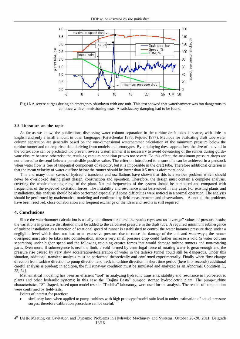
In order to prevent severe rejoinder of partially separated columns of water, the large vortex void in draft tube should be
avoided. As aforementioned, the pressure distribution in the draft tube cone is inherently uneven (due to the helical motion of the
flow), with the maximum pressure occurring at the wall and the minimum near the centre (Fig.11). To be more precise, the
minimum pressure occurs near the center of the vortex core, a complex rotating tube of water, vapor and air, which usual forms in
the draft tube. The vortex core is unstable as a result of the swirl (tangential component of absolute velocity of water outflowing
from the turbine runner) induced by the action of the turbine blades [14]. It is important to recall that transducers mounted on the
draft tube wall invariably record the greatest cross-sectional pressures, instead of the lowest pressures in the vortex core at the
centre of draft tube. In other words, even when the measured pressure is significantly high, the core pressure may well be at
vapor pressure (or air release pressure), or perhaps slightly above the vapor pressure if air has been injected into the system [7, 31].
Clearly, then, it is inappropriate to rely on the pressures measured on the draft tube cone to judge whether the minimum pressure
exceeds 0.05 MPa. Computational fluid mechanics (CFD) and numerical approaches clearly hold out some promise but they are
unfortunately far from being sound solutions to the challenge of measuring and predicting the possible range of draft tube
pressures and velocities due to the limited accuracy and numerical stability. The difficulty arises from many sources, including the
multi-phase, unsteady, asymmetrical, three-dimensional and oscillatory nature of the flow, and the complex interactions between
the flow and the machine unit (see photos in Fig.8 and Error! Reference source not found.11).
Overall, the inherent complexity and significance of these events demand an empirical approach to predict the occurrence of
water column separation in draft tubes. It is essential that all pressure data be carefully evaluated. This is particularly true since,
we emphasize, no similarity law is applicable to transient and/or two-phase flows [8, 18] while the equations based on similarity
still apply to the boundary conditions of the pump-turbine. In practice, the lowest transient pressure in the turbine system is
typically calculated based on one-dimensional waterhammer theory and thus represents the “cross-sectional average” value which
is lower than the measured one but higher than that in the vortex core (Error! Reference source not found.).
A predominant condition associated with reverse waterhammer is that the runner is effectively dewatered when the reverse
flow enters from the draft tube. Only if the axial component of flow velocity is lower than the allowable value (around 0.5 m/s)
will the impact force on the runner blades from the reversing water be small and unlikely to cause damage [31]. Another condition
should also be checked to prevent the so-called runner-lifting event; that is, the axial hydraulic force during the entire transient
must be smaller than the weight of rotating parts. In horizontal machines thrust bearing controls this force.
Any mathematical solution in the zone of instability is highly inaccurate and uncertain; fluctuations in the multiphase unsteady
vortex core further complicate the flow conditions, where model test data cannot be accurately transferred to the prototype.
Vortex at turbine partial load
Fig.11 Pressure distribution at cross-section (A-A) of draft tube and several relevant terminologies/values. When turbine
wicket gates close the inertia of water in tailrace tunnel pulls water out from the turbine and the void in the draft tube increases.
Photos: vortex core in the draft tube of the model at steady operation
Vortex at turbine overload

DOI: to be inserted by the publisher
4th
IAHR Meeting on Cavitation and Dynamic Problems in Hydraulic Machinery and Systems, October 26-28, 2011, Belgrade
10/16
3.1 Case Study: Reverse Waterhammer in Kaplan Turbine
To prevent reverse waterhammer, it is necessary to avoid dewatering of the runner during guide-vane closure. As is known, it
is impossible to prevent the emergence of absolute vacuum conditions under the turbine headcover (particularly in the case of high
head Kaplan turbines, even if the closure time is very long). The condition in this case, as already discussed, is that the mean
velocity of water outflow under the runner should be lower than a certain limiting small value [18, 19].
If measured data for the pressure distribution at the turbine head cover (Hk) is not available, the mean pressure drop through the
runner can be calculated from the axial hydraulic thrust Fa. The condition which prevents the runner from dewatering is Hk > Hvp
+ Hrez = 2 to 3 mWC, here Hvp is the vapor pressure and Hrez takes into account pressure pulsations and calculation accuracy. If
this condition is not satisfied, the mean maximum axial outflow velocity, C m, should me e t the following criterion,
m/s5.0 crm CC , which means that when the water flow reverses from the draft tube and strikes against the rotating runner
blades, provided the water flow reverses at the same velocity with which it leaves the runner, the impact force will be small and
not cause damage. The values of Hrez and Ccr should be corrected on the basis of practical experience gained in turbine operation.
An additional condition, the time during which the runner remains waterless, is of equal importance because both the cavity
size and the speed with which the water returning from the draft tube strikes at the runner depend on this duration. This condition
is especially suitable for analyzing oscillograms recorded when examining transient processes in waterpower plants. If the
duration of absolute vacuum is shorter than one second, it is considered that there is no danger of waterhammer accident. These
short pressure drops are caused by pressure fluctuations and oscillations in the generating unit [18, 19].
Calculations for the above-described turbine which experienced an accident (Fig.12) are presented in Fig.13. The lines of
guide-vane opening A, head H, discharge Q, and speed n, are obtained by calculating the unit quick closure. The line Fa shows the
hydraulic thrust variation as obtained by calculation from model test data. The mean pressure on the turbine headcover Hk can be
obtained from the pressure change in the draft tube and the hydraulic thrust variation. According to the adopted criterion, water
column separation occurs in the eighth second (Fig.13 (a)). The water outflow speed is C = 1.6 m/s > Crez = 0.5 m/s, and thus
there is a risk of an accident. In the case of two-speed of turbine guide vanes closure (Fig.13 b) with the total closure time 14.5 s,
the pressure Hk drops below its limiting value, Hk = -0.9 mWC < Hvp + Hrez = 2 to 3 mWC. But Cm = 0.3 m/s < Ccr = 0.5 m/s.
Consequently, there is no danger of an accident.
During the past years, incidents due to quick closure have occurred in some Kaplan turbines and the consequent waterhammer
resulted in great damages. The Faculty of Mechanical Engineering, University of Belgrade, and Association of Power Industry,
Belgrade, then jointly undertook a study on the reverse waterhammer in hydraulic turbines (managed by S. Pejovic), the key
results are summarized in a series of articles [7Error! Reference source not found., 17, 25, 31, 32]. The investigators also
describe an accident that had occurred at a 22 MW turbine-generator unit (Fig.14) when it was operating at night with an output of
8 MW. The failure of a governor caused the guide-vanes to suddenly open leading to a rapid escalation in power output. Power
oscillations between 20 and 25 MW were recorded by monitoring instruments and load rumbles were heard from the turbine room.
In response, the unit was shut down by pressing the emergency shut-off button which disconnected the generator from the network
and the unit overspeed control device went into operation. When the machine was to stop, a banging noise was heard from the
turbine and water was observed leaking out through the turbine head cover. Subsequently, one of the runner blades was found to
be broken at the root (Fig.1). The fracture line traversed the blade obliquely from the hub towards the inlet edge. A smaller part of
the blade root and inlet section remained attached to the runner hub, while the larger part was broken off. The fracture revealed no
cracks or casting defects and no signs of material fatigue. It was clear that the break had started on the lower part of the blade.
Another power plant equipped with identical turbine runners experienced a similar catastrophic accident one year later.

DOI: to be inserted by the publisher
4th
IAHR Meeting on Cavitation and Dynamic Problems in Hydraulic Machinery and Systems, October 26-28, 2011, Belgrade
11/16
Fig.12 Quick closure from power output of 16 MW. Turbine closure time is 4 s; a0 (percent) = guide vane opening; 0 =
runner blade inclination, n0%= rotational speed; hsp (mWC) = pressure in spiral casing; and h1 and h2 = pressure on turbine head
cover. It is important to notice that the pressure on the turbine head cover (h1 and h2) becomes an absolute vacuum at the end of
the servomotor stroke. This means that an air-vapor cavity is formed above the runner.
(a) (b)
Fig.13 Calculation of unit quick closure; A = guide vane opening; H = head; Q = discharge; n = rotational speed; Hk = mean
pressure on turbine head cover; Fa = hydraulic thrust; Cm = meridional velocity of water at runner outlet.

DOI: to be inserted by the publisher
4th
IAHR Meeting on Cavitation and Dynamic Problems in Hydraulic Machinery and Systems, October 26-28, 2011, Belgrade
12/16
Fig.14 Runner blade broken in the accident of quick guide-vane closing
3.2 Case Study: Turbine with Long Tailrace Tunnel
In this case, a power plant has eight 250 MW units with each pair of units sharing a common penstock and 500 m tailrace
tunnel (Fig.15). The units are submerged 13 m below the tailwater to prevent cavitation. The simultaneous load rejection of two
units would cause water column separation and subsequent rejoinder in the draft tube, an event that could result in serious damage
to both machinery and the water conveyance system. Air admission was proposed to dampen the surge, but it is difficult to keep it
operational at all times [4, 27, 28]. The proper amount of air injection is able to protect system from normal operational transients
[1, 2, 2624] but not from full runaway conditions if too little air is pumped into the draft tube from the beginning to the end of the
waterhammer transitions. Although the probability of runaway is low, the associated damages could be enormous with
unpredictable catastrophic consequences. Therefore, the risks and potential costs of acceptable damage at full runaway condition
should be carefully scrutinized. A proper submergence at no additional cost could have been done at the early design stage and
during project reviews [23, 24]. The risk of draft tube water column separation was pointed out at an early stage [18, 19], but it
was then too late to increase submergence as the plant was already under construction.
Upon commissioning of the plant, the hydraulic transient in the draft tube during load rejection had been excessive, as already
described and calculated. It was apparent that the guide vane closing had resulted in water column separation during load rejection
with only 75% partial load at one unit (Fig.16). The field tests confirmed that the partial water column separation could take
place even if the measured minimum pressure at draft tube cone is above vapor pressure.
Significant effort was made, based on the water hammer calculations associated with site load rejections, to search for an
improved break point and closing rates of wicket gate closure law. In fact, a severe surge during an emergency shutdown of one
unit implied that the trial-and-error method of breakpoint adjustment was too dangerous, and a better solution was needed. Thus, a
Panel of Experts was appointed to identify the origins of the pressure surges and to offer suggestions to solve the problem [4, 5].
Fig.15 The second phase of hydroelectric plant under construction; the first phase in operation partially protected by air
injection into the draft tube
DOI: to be inserted by the publisher
4th
IAHR Meeting on Cavitation and Dynamic Problems in Hydraulic Machinery and Systems, October 26-28, 2011, Belgrade
13/16
Fig.16 A severe surges during an emergency shutdown with one unit. This test showed that waterhammer was too dangerous to
continue with commissioning tests. A satisfactory damping had to be found.
3.3 Literature on the topic
As far as we know, the publications discussing water column separation in the turbine draft tubes is scarce, with little in
English and only a small amount in other languages (Krivtchenko 1975; Pejovic 1977). Methods for evaluating draft tube water
column separation are generally based on the one-dimensional waterhammer calculation of the minimum pressure below the
turbine runner and on empirical data deriving from models and prototypes. By employing these approaches, the size of the void in
the vortex core can be predicted. To prevent reverse waterhammer it is necessary to avoid dewatering of the runner during guide-
vane closure because otherwise the resulting vacuum condition proves too severe. To this effect, the maximum pressure drops are
not allowed to descend below a permissible positive value. The criterion introduced to ensure this can be achieved in a penstock
when water flow is free of tangential component of velocity, but it is impossible in the draft tube. Therefore additional criterion is
that the mean velocity of water outflow below the runner should be lower than 0.5 m/s as aforementioned.
This and many other cases of hydraulic transients and oscillations have shown that this is a serious problem which should
never be overlooked during plant design, construction and operation. Therefore, the design must contain a complete analysis,
covering the whole operating range of the plant. Natural frequencies of the system should be computed and compared with
frequencies of the expected excitation forces. The instability and resonance must be avoided in any case. For existing plants and
installations, this analysis should be also performed especially if some difficulties were noticed in a normal operation. The analysis
should be performed by mathematical modeling and confirmed by field measurements and observations. As not all the problems
have been resolved, close collaboration and frequent exchange of the ideas and results is still required.
4. Conclusions
Since the waterhammer calculation is usually one-dimensional and the results represent an “average” values of pressure heads;
the variations in pressure distribution must be added to the calculated pressure in the draft tube. A required minimum submergence
of turbine installation as a function of rotational speed of runner is established to control the water hammer pressure drop under a
negligible level which does not lead to an excessive pressure rise to cause the damage of the unit and waterways; the runner
overspeed must also be taken into consideration, since a very small pressure drop could further increase a void (a water column
separation) under higher speed and the following rejoining creates forces that would damage turbine runners and non-rotating
parts. Even more, if submergence is near the limit, a void formed by centrifugal force of rotating water is great enough and the
pressure rise caused by very slow acceleration/deceleration of water in the tailrace tunnel could still be dangerous. Under this
situation, additional transient analysis must be performed theoretically and confirmed experimentally. Finally when flow change
direction from turbine direction to pump direction and back in turbine direction in short time period (here in 3 seconds) additional
careful analysis is prudent; in addition, the full runaway condition must be simulated and analyzed as an Abnormal Condition [1,
23, 24].
Mathematical modeling has been an efficient "tool" in analyzing hydraulic transients, stability and resonance in hydroelectric
plants and other hydraulic systems; in this case the "Bajina Basta” pumped storage hydroelectric plant. The pump-turbine
characteristics, “S”-shaped, based upon model tests in "Toshiba" laboratory, were used for the analysis. The results of computation
were confirmed by field-tests.
Points of interest for practice:
similarity laws when applied to pump-turbines with high prototype/model ratio lead to under-estimation of actual pressure
surges; therefore calibration procedure can be useful;

DOI: to be inserted by the publisher
4th
IAHR Meeting on Cavitation and Dynamic Problems in Hydraulic Machinery and Systems, October 26-28, 2011, Belgrade
14/16
the similarity applicable to transients is untruth (inaccurate), therefore all data must be carefully evaluated as really there
is no similarity between transient and/or two-phase flows.
pump-turbines with “S”-shaped characteristics enter the fourth-quadrant (reverse pump operation) regularly after a trip-
out from turbine operation, even if the wicket-gates are closed down rapidly as designed to prevent high speed rise and
minimize time spent in unstable zone or operation decreasing resonance effects.
It will be interesting to monitor operational records of these machines with one key question in mind: will cavitation and
hydraulic vibration cause more trouble than usual or not?
Those who design and construct complex systems have to face many challenges. Even routine issues such as the trade-off
between capital and operating costs invariably involve an assessment of events that might happen in the future, a realm of great
uncertainty. Although this paper discusses specific cases, the goal is not to cast blame, assign fault, or imply that the related
decision-making is easy. In almost all such cases, only hindsight is sharp and clear. However, these issues have arisen before, and
will continue to arise, until the associated challenges are brought more consciously into the open where they can be discussed and
debated. The over-riding duty of engineers is to act in the best interest of both clients and the public [9].
Certainly the design and operation of any power system requires a delicate balance between certain competitive objectives.
One crucial issue is related to the phenomenon of water column separation in tailrace tunnel, particularly following a transient
turbine operation (e.g., the load rejection, emergency closure, and runaway).
Since water hammer calculations are usually based on one-dimensional models, the results represent average values of pressure
heads and, thus, the variation of pressure over the draft tube cross-section must be carefully considered. Moreover, the speed
increment of the runner, particularly in runaway condition, is crucial since the voids formed by the centrifugal force of the high
speed rotating water can be large; the pressure rise caused by even slow accelerations/decelerations of the tailrace water could
have a strong influence on void collapse. Therefore, transient analysis must be thoroughly performed and confirmed
experimentally. A larger safety margin is prudent for the draft tube coefficient, particularly given the complex and difficult-to-
model nature of these transient flows.
Air admission is way of controlling water column separation. Field tests show that the injection of compressed air reduces the
severity of transients during load rejection, even for insufficiently submerged turbines. Thus, air injection is useful in underground
power plants where the potential to increase the power output is constrained by the excessive negative surges in draft tubes.
However, being a reactive and real time safety concept, it relies on the controller‟s dexterity and skill, and it must be carefully
designed tested and maintained. It also does not rectify shortcomings of inadequate submergence or defects in other design
criteria, which are, in part, revealed through thoughtful case studies of actual events in operational facilities.
Nomenclature
A
Aav
a
ao
a/amax
ca
cu
D
e
g
h
h1/h2
hat
hDT
hs
hsp
hvp
k
k
Lx
n
n1’
amplitude of pressure pulsations [m]
average amplitude of pressure fluctuation
in draft tube
guide vane opening
guide vane opening
relative guide vanes openings
axial component of flow velocity
tangential component of flow velocity
draft tube tailrace diameter
relative energy measured from model tests
gravity acceleration
turbine net head
pressure on turbine head cover
atmospheric pressure
pressure at runner outlet, pressure
measured at draft tube cone
suction head
pressure in spiral casing (mWC)
the vapor pressure
empirical coefficient
pressure distribution factor in the
cross-section of draft tube cone
length of tailrace tunnel [m]
rotational speed of turbine unit
unit speed
no
nr
v0
vdt
Ts
s%
u
ue
V
av
uv
z
o
plant
h
hdt
rotational speed
rated speed of turbine unit
flow velocity in the tailrace tunnel
flow velocity at the runner outlet
closing time of guide vanes [s]
the percentage of vacuum under the runner cross-section
surface area
the peripheral velocity of the runner corresponding to the
measured minimum pressure and overspeed condition
the peripheral velocity of the runner corresponding to the
simulated minimum pressure
critical vacuum in the draft tube (mWC)
axial flow velocity (perpendicular to the draft tube
cross-section) per turbine head h = 1 m
tangential flow velocity per turbine head h = 1 m
vertical position of the point measured from the lower
reservoir level, if the point is below the tailrace water
level z > 0.
runner blade inclination
plant cavitation coefficient
turbine dimensionless head rise
dimensionless speed rise
turbine head rise due to waterhammer
waterhammer pressure rise in the draft tube (pressure
drop is negative)

DOI: to be inserted by the publisher
4th
IAHR Meeting on Cavitation and Dynamic Problems in Hydraulic Machinery and Systems, October 26-28, 2011, Belgrade
15/16
References
1. ASME HPTC (Bryan K., Pejovic S., co-authors). The Guide to Hydropower Mechanical Design, 2011, new edition
under review.
2. ASME HPTC (Pejovic S., co-author). The Guide to Hydropower Mechanical Design, HCI Publication, 1996.
3. Borciani S., Thalman R., Influence of on Average and Instantaneous Characteristics of Turbines and Pump-Turbines (in
Franch), La Hoille Blabnche, 1982, No. 2/3
4. Brekke H., Jacob, Th. Kiani A.S., Leyland B., Pejovic S. (2004). Transient Problems upon Load Rejection Masjed-e
Soleyman Case Study. Portugal, Hydro 2004, paper 4.01
5. Brekke H., Jacob Th., Leyland B., Pejovic S. (2003) “Transient Problems upon Load Rejection", Masjed-e-Soleyman
Panel of experts report.
6. Gajic A., A Contribution to the Investigation of Unsteady-State Phenomena in Hydro Power Plants (In Serbo-Croatian),
part of Ph.D. thesis, University of Belgrade, Yugoslavia, 1983.
7. Krivtchenko G. I., Arshenevsky N. N., Kvyatkovskaya E. V., Klabukov V. M. (1975). Hydraulic Transients in
Hydroelectric Power Plants, (in Russian), Moskva.
8. Lee T. S., Pejovic S. (1996). Air Influence on Similarity of Hydraulic Transients and Vibrations. Transaction of the
ASME, Journal of Fluids Engineering, Vol. 118, December 1996.
9. Marston D.L. (1996). Law for Professional Engineers, McGraw-Hill-Ryerson.
10. Martin C. S., Post Accident Report, Frequency, Resonance, and Hydraulic Transient Analysis, Bhira Pumped Storage
Installation, the Tata Power Company Limited, 1995.10
11. Martin C. S.,Stability of Pump/Turbine During Transient Operation, Fifth BHRA International Conference,on Pressure
Surges, Hanover, West Germany, 1986,
12. Murray H., Hydraulic Topics in Development of High Head Pump-Turbine and Investigation on Related Problems in
Japan, General Lecture, 9th IAHR Symposium on Hydraulic Machines and cavitation, Tokyo, Japan, 1980, pp. 1 - 14.
13. Nicolet C., Alligné S., Kawkabani B., Koutnik J., Simond J-J., Avellan F., Stability Study of Francis Pump-Turbine at
Runaway, 3rd
IAHR International Meeting of the Workgroup on Cavitation and Dynamic Problems in Hydraulic Machinery and
Systems, October 14 – 16, 2009, Brno, Czech Republic. Link:
http://www.powervision-eng.ch/Profile/Publications/pdf/IAHR_WG1_2009_1.pdf
14. Ohashi, H., Editor, Vibration and Oscillation of Hydraulic Machinery, Avebury Technical, 1991.
15. Pejovic S., Chapter 12 Hydraulic Transients, ASME Guide to Hydropower Mechanical Design, Prepared by ASME
HPTC, 2011, new edition under review.
16. Pejovic S., Chapter 12 Hydraulic Transients, The Guide to Hydropower Mechanical Design, Prepared by ASME HPTC,
HCI Publication, 1996 pp. 374.
17. Pejovic S., Hydraulic Transients and Reverse Waterhammer (in Serbo-Croatian). Institut Masinskog fakultcta, Beograd
1977.
18. Pejovic S., Mesjad-E-Soleyman Analysis of Draft Tube Flap Gate, Hydro Québec International, RSW International,
Teheran, report, 1998.
19. Pejovic S. (1998b) Mesjad-E-Soleyman Analysis of Draft Tube Flap Gate, Hydro Québec International, RSW
International, Teheran, report.
20. Pejovic S., Pressure Surges and Vibrations in Hydropower Plants - Experiences in Yugoslavia, The Current State of
Technology in Hydraulic Machinery, International Editorial Committee Book Series on Hydraulic Machinery, Gower
Technical ,1989, pp. 177-204.
21. Pejovic S., Similarity in Hydraulic Vibrations of Power Plants, Joint ASCE/ASME Mechanics, Fluids Engineering, and
Biomechanics Conference, San Diego, USA 1989, American Society of Mechanical Engineers, Paper 89-FE-4, pp. 5
22. Pejovic S., Troubleshooting of turbine vortex core resonance and air introduction into the draft tube, IAHR Symposium,
Lausanne, Switzerland, 2002.
23. Pejovic S., Boldy A.P. (1992). Guidelines to Hydraulic Transient Analysis of Pumping Systems, P & B Press, Belgrade –
Coventry.
24. Pejovic S., Boldy A.P., Obradovic D., Guidelines to Hydraulic Transient Analysis, Technical Press, England, 1987.

DOI: to be inserted by the publisher
4th
IAHR Meeting on Cavitation and Dynamic Problems in Hydraulic Machinery and Systems, October 26-28, 2011, Belgrade
16/16
25. Pejovic S., Gajic A., Obradovic D., (1980c), Reverse Water Hammer in Kaplan Turbines, IAHR Symposium, Tokyo, pp.
489-499.
26. Pejovic S., Karney B.W., Zhang Q., Kumar G., Smaller Hydro, Higher Risk, IEEE Trans CD, 2007.
27. Pejovic S. Karney W.B. and Zhang Q. (2004b), Masjed-E-Soleyman Hydraulic Transients. Water Column Separation in
the Draft Tube, Draft Tube Surges, Panel of Experts Mission of November, Report.
28. Pejovic S., Karney B., Zhang Q., Water Column Separation in Long Tailrace Tunnel, HYDROTURBO, Brno 2004
29. Pejovic S. Karney W.B. and Zhang Q. (2004), Masjed-E-Soleyman Hydraulic Transients. Water Column Separation in
the Draft Tube, Draft Tube Surges, Panel of Experts Mission of November, Report.
30. Pejovic S., Krsmanovic Lj., Gajic A., Reverse Waterhammer and Accident in Hydro Power Plant "Zvornik" (in Serbo-
Croatian), Masinski Fakultet, Belgrade, 1978, pp. 90.
31. Pejovic S., Krsmanovic Lj., Gajic A., Obradovic D., Kaplan Turbine Incidents and Reverse Waterhammer, Water Power
and Dam Construction, 1980.
32. Pejovic S., Krsmanovic Lj., Jemcov R., Crnkovic P., Unstable Operation of High-Head Reversible Pump-Turbines,
IAHR 8th Symposium, Leningrad, 1976.
33. Pejovic S., Obradovic D., Gajic A., Hydraulic Transients in a Power Plant - Mathematical Modeling Confirmed by Field
Tests, Hydrosoft 84, Portoroz, 1984, pp. 5.57-5.67.
34. Time V.A. (1960). Reverse Water Hammer in the Kaplan Turbine Drat Tube (in Russian). Electricheskie Stancii, No 3,
1960.
35. Wylie E.B., Streeter V.L., Fluid Transients, McGraw-Hill, 1993.