analysis of rotor faults effects on submersible induction
TRANSCRIPT

Abstract—This paper analyzes effects of squirrel cage faults
on submersible induction motors efficiency at steady-state condition. There are a lot of studies about effects of the cage faults on motor performance. Especially, the effects of the cage faults on the motor parameters such as current, torque and speed are well known. Unlike the literature, cage fault effects on efficiency are analyzed in this study. Furthermore, fluctuations and mean value changes resulting from the rotor faults are ranked according to size of these faults. Healthy and five different faults were investigated by using 10 HP, 25 HP, 30 HP and 50 HP submersible induction motors in both simulations and experiments. Time stepping finite element method solution was used to compute motor quantities in the simulation. Good agreement was achieved between simulation and experimental results. The effects of rotor faults on motor efficiency were clearly ranked according to size of faults.
Index Terms— Induction motors, energy efficiency, finite element methods, rotor.
I. INTRODUCTION NDUCTION motors are widely used in industry because of their durability and low production costs. They are
generally used to drive moving mechanical loads. Unlike traditional induction motors, submersible induction motors (SIMs) are used to drive pump to carry underground water to the surface, seawater lift service on offshore platforms and floaters or other storage facilities. Although working principles are same with traditional induction motors, it has some small differences in their structures. Diameter of the motor is limited because of size of wells drilled. Most SIMs are designed to fit in four inch, six inch wells or larger. To increase motor power, rotor length is extended because of the limited diameter. Therefore, lengths of SIMs are longer and their diameters are shorter from traditional induction motors.
Despite their reliability and stiffness of SIMs, some faults may still occur. Majority of faults occur at stator side but some of they occur in rotor. Rotor faults may result from production faults or from mechanical, environmental, electromagnetic or thermal pressure exerted on the unit [1].
Manuscript recevied May 14, 2013. This work supported by Scientific
Research Project Coordinating of Selçuk University (SUBAP). H. Arabacı is with the Department of Electrical and Electronics
Engineering, Technolagy Faculty, Selcuk University, 42075, Konya, Turkey. (corresponding author’s phone: +90-332-22333377; fax: +90-332-2412179; e-mail: [email protected]).
O. Bilgin is with the Department of Electrical and Electronics Engineering, Engineering Faculty, Selcuk University, 42075, Konya, Turkey. (e-mail: [email protected]).
Faults other then production errors will occur as small-scale faults. Because of above listed pressures, initial faults may grow and may result in increasing the scale of potential subsequent faults [2]. The faults negatively affect motor performance [3]. The effects of faulted rotor are recorded as unbalanced motor currents, torque fluctuations, increasing in loss, larger thermal pressures and degradation of transient performance. Symptoms of the faults are small-scale and could not be detected by simple methods. Even though the rotor fault is at an early stage or it reaches a certain size, the motor does not stop and the fault can not be understood. It requires deeply analysis. Losses of energy in this process have not been taken into account. Especially considering irrigation systems, a lot of energy loss arises.
Most of studies about the rotor faults have been conducted to detection and diagnosis of the faults [4]-[22]. In the most of such studies, a current analysis method has been adopted [12]-[27] and a rotor with one broken bar has been studied as the rotor fault. Vibration analysis [28] and flux analysis [29]-[31] are also available in the diagnosis of rotor faults. While some of these studies have examined 2 or 3 broken bars or a broken short circuit ring, they have focused on the available indicators of the motor current and concentrated on methods which are for diagnosis rather than effects on performance.
A number of studies have proposed to investigate the effects of broken rotor bars and on their performances in many decades. Initially, motor performance analyses were made by using equivalent circuit of induction motor [32]. In later years, magnetic field [33] and differential equations were used for dynamic behavior of induction motor. Solutions of these equations were done by computer [34]. The development of computers and software has enabled the use of finite element methods (FEM) to solve the equations of mathematical model of induction motors. [35] presents detail induction motor performance computation and prediction using combined finite element-state space model of induction motor which includes rotor bars. Motor current, torque and rotor-stator losses are analyzed within context of the performance but the efficiency is unavailable. In [36], effects of broken bar faults on motor torque and current are investigated by using time-stepping coupled finite element-state space modeling approach. So, it is shown that the broken bar fault simulated and analyzed by using FEM. [37] analyzes current spectrum, torque, speed, magnetic flux distribution, magnetic potential vector and magnetic flux density of motor by time-stepping finite element method (TSFE) in a healthy and with broken rotor
Analysis of Rotor Faults Effects on Submersible Induction Motor’ Efficiency
Hayri Arabacı and Osman Bilgin
I
Proceedings of the World Congress on Engineering and Computer Science 2013 Vol I WCECS 2013, 23-25 October, 2013, San Francisco, USA
ISBN: 978-988-19252-3-7 ISSN: 2078-0958 (Print); ISSN: 2078-0966 (Online)
WCECS 2013

bar. The field, current, torque, speed, and their relationship are analyzed and used for diagnosis. [38] investigates the effects of rotor bar faults by TSFE approach on motor performance which contains stator current waveforms, current density and magnetic force distribution. TSFE method is used for modeling of induction motor with broken rotor bars in [39]. It investigated and ranked the effects of broken bar faults on amplitudes of harmonics components of current and torque. In this modeling, geometrical and physical characteristics of all parts of the motor, spatial distribution of stator windings, slots on both sides of the air gap and non-linear characteristic of the core materials are included. That is while the current of the broken bar was taken to be non-zero, instead resistance of the broken bar was considered large enough. [40] analyzes performance of single phase induction motor by using 2D TSFE approach. Simulation results are verified by experimental result. The current, torque and efficiency of motor were investigated for performance analysis.
The current, torque, speed and magnetic flux of motor have been included in to performance content at the studies about motor performance analysis so far. Furthermore the size of rotor faults effect on the motor efficiency is not known in detail. So in the presented study, efficiency of motor are included to the motor performance and the effects of rotor faults on motor efficiency under steady-state condition is ranked according to size of the rotor faults.
Three-phase, 50Hz, 380V, two poles, 10 HP, 25 HP, 30 HP and 50HP squirrel cage submersible induction motors were used in experiments and in simulations conducted on the 5 different types of faults and on a healthy rotor. Within the scope of the present study, five different rotor faults were analyzed. The efficiency of motor was analyzed in the scope of the motor performance. The effects on the efficiency were detected via comparison between the values of a healthy rotor and faulted rotors.
The simulations results have been obtained by using the FEM solution in order to investigate the effects of the broken rotor bars. FEM is able to compute the magnetic field distribution within the motor using geometry and magnetic parameters of the motor. Having the magnetic field distribution, other quantities of the motor can be obtained [41],[42]. Modeling of the rotor cage is the first step in the design of the SIMs. Because the field picture totally changes, the situation is more complex in simulation of rotor cage faults [43]. The finite-element analysis (FEA) can be used to model the induction motor with the rotor cage modeling [44]. The FEA has been coupled to circuit simulation. This external circuit coupling allows to simulate the operating conditions of the induction motor with the real power-supply connections [45]. Fixed load was used loading of the motor in simulation.
Unlike the traditional induction motor, submersible motor’ length is longer and it’s diameter is shorter. So, material of rotor shaft will be important. If the material is not magnetic, leakage flux in motor will be early reached to saturation. Therefore, the shaft material should be magnetic material in simulation model. This material in other
induction motors is generally chosen nonmagnetic [46]. The following assumptions have been used for
simplification in the FEM solution procedure for SIMs, similar to that in classical induction motor [38].
• The rotor bars are insulated from the rotor core, and there is no direct electrical contact between the rotor bars and the rotor core.
• The leakage on the outer surface of the stator and the inner surface of the rotor is neglected.
• The 2-D domain is considered, the magnetic vector potential and the current density have only the axial z component.
• Displacement current is neglected because the frequency of the source is very low.
Geometrical and physical characteristics of all parts of the motor, spatial distribution of stator windings, slots on both sides of the air gap and non-linear characteristic of the core materials are included in the present modeling as in [39].
II. MATERIAL AND METHOD Stator current has been generally used in the
investigating of rotor faults. The faults affect the current according to motor slip as in Equation (1).
fksfb )21( , k = 1,2,3,.... (1)
Where f is main frequency and s is motor slip. The effects cause fluctuations on the current. Because the current is directly related to other motor’ outputs, the motor performance is indirectly affected by the fluctuations. In this study, the motor efficiency is evaluated. The following two criteria are used for investigating:
- The ratio of fluctuations, - The change in the mean values.
valueMin. valueMax. Min value - valueMax.*2 ratio nsfluctuatio The
(2)
The fluctuation ratio is calculated according to Equation (2). These outputs are analyzed for each fault size and they are compared with other fault sizes and healthy rotor.
Broken rotor bar faults and end ring fault are mainly caused by manufacturing defects. Especially, rotor bars of low and medium power motors are generally made of casting. Small defects may occur during casting process and it grows and causes important faults. Copper bar are generally used in rotor of the SIMs, while welding bars to end rings some defect (i.e. bad welding and small crack in end rings) may occur. The analyzed rotor faults are shown as follows:
- A rotor with one broken rotor bar, - A rotor with two adjacent broken rotor bars, - A rotor with three adjacent broken rotor bars, - A rotor with high resistance rotor bar, - A rotor with broken end ring (only in experimental
study). The simulations and experiments were made by using
Proceedings of the World Congress on Engineering and Computer Science 2013 Vol I WCECS 2013, 23-25 October, 2013, San Francisco, USA
ISBN: 978-988-19252-3-7 ISSN: 2078-0958 (Print); ISSN: 2078-0966 (Online)
WCECS 2013

four different squirrel cage SIMs. The specifications of motors were; Motor1: 50 HP, 8’’, with 18 bars, 380V, 2 poles and 50 Hz. Motor2: 30 HP, 8’’, with 18 bars, 380V, 2 poles and 50 Hz. Motor3: 25 HP, 6’’, with 22 bars, 380V, 2 poles and 50 Hz. Motor4: 10 HP, 6’’, with 22 bars, 380V, 2 poles and 50 Hz.
III. SIMULATION AND RESULTS A mathematical model, in which rotor parameters can be
changed, is needed to simulate the rotor cage faults. Therefore, the model of squirrel cage is included within the mathematical model of SIMs. To solve such a model by circuit solutions requires a lot of assumptions (very small air gap, infinite magnetic permeability, magnetic saturation etc.). But in the FEM solution fewer assumptions are needed. So in this study simulation of SIMs were made by using FEM. FEM analysis has been coupled to the circuit simulation. This external circuit coupling allows to simulate the operating with the real power-supply connections. Time stepping transient magnetic 2D FEM were used in the solutions.
In the FEM modeling, benefiting from symmetry of motor structure reduces to the number of calculations. Because the used motors in this study have 2 poles, half of the motors can be modeled for simulations, but we used whole of motor which is need to simulate the one broken bar fault.
A. Motor Efficiencies in The Results of Simulations The efficiency is one of the important outputs of motor.
The fluctuation in the wave forms of current affects the mechanical power and input power of the motor. Therefore, the efficiency changes in time. There are considerable fluctuations according to size of fault. The ratios of the size of these fluctuations are listed in Table 1. The fluctuations corresponding to each rotor cases are clearly shown in this table. The decrease in mean value of the efficiency is shown more clearly in the Table 2.
TABLE I
FLUCTUATION RATE OF EFFICIENCIES
Healthy Rotor [%]
High Res. [%]
One Broken
Bar [%]
Two Broken
Bars [%]
Three Broken
Bars [%]
Motor1 0.3 1.1 2.2 4.9 8.1 Motor2 0.2 1.5 1.9 4.4 7.3 Motor3 0.4 1.0 1.7 3.6 5.9
Motor4 0.7 1.3 2.0 3.9 6.1
TABLE II MEAN VALUE OF EFFICIENCIES
Healthy Rotor [%]
High Resistance
[%]
One Broken
Bar [%]
Two Broken
Bars [%]
Three Broken
Bars [%]
Motor1 86.09 85.98 85.70 84.93 83.86 Motor2 81.84 81.80 81.69 81.14 80.29 Motor3 82.10 81.99 81.73 81.08 80.21
Motor4 81.12 81.07 80.85 80.30 79.54
IV. EXPERIMENTAL STUDY AND TEST RESULTS The motors (Motor1, Motor2, Motor3 and Motor4) were
tested in the motor factory by using experiment system. The purposed five different rotor faults were created in the factory at the production phase for each motor. In order to ensure accuracy of measurements, each rotor fault was created separately and passed through each assembly phase. Data were obtained in steady state operation under nominal loaded condition for each fault.
To obtain broken rotor bar faults, a small part (5 mm length) is cut from the mid side of the rotor bar and the two parts of bar are stacked from both sides. So conductivity of the bar decreased to zero. Broken rotor bar photograph is given in Fig. 1. The broken end-ring fault is obtained in a similar way. A bar with highly resistance is obtained by drilling the bar. So the conductivity of the bar decreases to %96 from %100 as shown Fig. 2.
Figure 1. Photographs of broken rotor bar parts and rotor.
Figure 2. Obtaining of a bar with high resistance.
The motors were tested in the submersible motor factory by using test unit. The tested motor was loaded by DC generator. Loading of motor is leveled by using resistors which conducted to the generator. The photographs of the used experiment system are given in Fig. 3 and the block diagram of the system is given in Fig. 4.
Proceedings of the World Congress on Engineering and Computer Science 2013 Vol I WCECS 2013, 23-25 October, 2013, San Francisco, USA
ISBN: 978-988-19252-3-7 ISSN: 2078-0958 (Print); ISSN: 2078-0966 (Online)
WCECS 2013
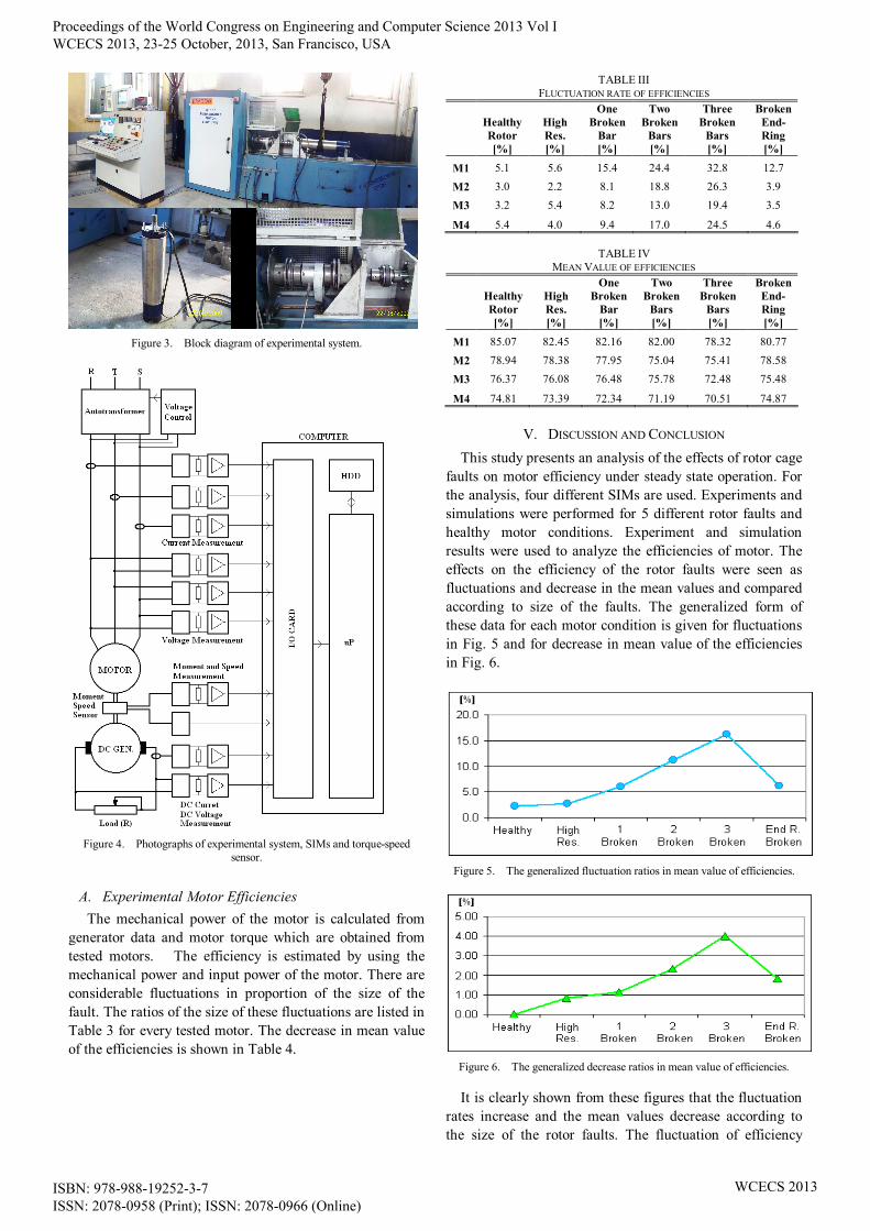
Figure 3. Block diagram of experimental system.
Figure 4. Photographs of experimental system, SIMs and torque-speed
sensor.
A. Experimental Motor Efficiencies The mechanical power of the motor is calculated from
generator data and motor torque which are obtained from tested motors. The efficiency is estimated by using the mechanical power and input power of the motor. There are considerable fluctuations in proportion of the size of the fault. The ratios of the size of these fluctuations are listed in Table 3 for every tested motor. The decrease in mean value of the efficiencies is shown in Table 4.
TABLE III FLUCTUATION RATE OF EFFICIENCIES
Healthy Rotor [%]
High Res. [%]
One Broken
Bar [%]
Two Broken
Bars [%]
Three Broken
Bars [%]
Broken End-Ring [%]
M1 5.1 5.6 15.4 24.4 32.8 12.7 M2 3.0 2.2 8.1 18.8 26.3 3.9 M3 3.2 5.4 8.2 13.0 19.4 3.5
M4 5.4 4.0 9.4 17.0 24.5 4.6
TABLE IV MEAN VALUE OF EFFICIENCIES
Healthy Rotor [%]
High Res. [%]
One Broken
Bar [%]
Two Broken
Bars [%]
Three Broken
Bars [%]
Broken End-Ring [%]
M1 85.07 82.45 82.16 82.00 78.32 80.77 M2 78.94 78.38 77.95 75.04 75.41 78.58 M3 76.37 76.08 76.48 75.78 72.48 75.48
M4 74.81 73.39 72.34 71.19 70.51 74.87
V. DISCUSSION AND CONCLUSION This study presents an analysis of the effects of rotor cage
faults on motor efficiency under steady state operation. For the analysis, four different SIMs are used. Experiments and simulations were performed for 5 different rotor faults and healthy motor conditions. Experiment and simulation results were used to analyze the efficiencies of motor. The effects on the efficiency of the rotor faults were seen as fluctuations and decrease in the mean values and compared according to size of the faults. The generalized form of these data for each motor condition is given for fluctuations in Fig. 5 and for decrease in mean value of the efficiencies in Fig. 6.
Figure 5. The generalized fluctuation ratios in mean value of efficiencies.
Figure 6. The generalized decrease ratios in mean value of efficiencies.
It is clearly shown from these figures that the fluctuation rates increase and the mean values decrease according to the size of the rotor faults. The fluctuation of efficiency
Proceedings of the World Congress on Engineering and Computer Science 2013 Vol I WCECS 2013, 23-25 October, 2013, San Francisco, USA
ISBN: 978-988-19252-3-7 ISSN: 2078-0958 (Print); ISSN: 2078-0966 (Online)
WCECS 2013

reaches up to 32%. And its mean value is reduced by 4%. All of these show that the effects of the rotor faults are significantly effective on motor performance. It is considered that rotor faults generally occur as small faults and grow over time. Moreover their symptoms could not be detected by simple methods. So, the motor does not stop and the fault can not be understood until the rotor fault is at an early stage or it reaches a certain size.
- Losses of energy in this process are not taken into account. Especially considering irrigation systems, a lot of energy loss arises. This study clarifies these losses.
Finally, efficiency was analyzed for motor with rotor faults under steady state operations by this paper.
- A notable decrease in efficiency is shown as long as fault grows.
- These effects are ranked according to size of rotor faults and analyzed the effects of such faults on motor efficiency.
ACKNOWLEDGMENT The study has been supported by Scientific Research
Project of Selcuk University.
REFERENCES [1] A.H. Bonnett, G.C. Houkup, “Cause and analysis of stator and rotor
faults in three-phase squirrel-cage induction motors”, IEEE Transactions on Industry Applications 28, No. 4, 1992, pp. 921–937.
[2] J. Penman, A. Stavrou, “Broken Rotor Bars Their Effect on the Transient Performance of Induction Machines”, IEE Proc.-Electr. Power Appl., Vol. 143, No. 6, 1996, pp. 449-457.
[3] X. Ying, “Characteristic Performance Analysis of Squirrel Cage Induction Motor with Broken Bars”, IEEE Transactions on Magnetics, Vol. 45, No. 2, 2009, pp. 759-766.
[4] H. Arabaci, O. Bilgin, “Automatic Detection and Classification of Rotor Cage Faults in Squirrel Cage Induction Motor”, Neural Computing and Applications, Vol. 19, No. 5, 2010, pp. 713-723.
[5] M. Haji, H.A. Toliyat, “Pattern recognition – a technique for induction machines rotor fault detection ‘Eccentricity and broken bar fault’ “, IEEE Industry Applications Conference Thirty-Sixth IAS Annual Meeting. Vol. 3, 2001, pp. 1572-1578.
[6] G. Didier, E. Ternisien, O. Caspary, H. Razik, “Fault Detection of Broken Rotor Bars in Induction Motor Using a Global Fault Index”, IEEE Transactions on Industry Applications, Vol. 42, No. 1, 2006, pp. 79-88.
[7] M. Chow, S. O. Yee, “Methodology for on-line incipient fault detection in single-phase squirrel-cage induction motors using artificial neural networks”, IEEE Transactions on Energy Conversion, Val. 6, No. 3, 1991, pp. 536-545.
[8] H. Arabaci, O. Bilgin, “Neural Network Classification and Diagnosis of Broken Rotor Bar Faults by Means of Short Time Fourier Transform”, International MultiConference of Engineers and Computer Scientists, Hong Kong, 2009, pp. 219-223.
[9] R. R. Schoen, T. G. Habetler, “Effects of time-varying loads on rotor fault detection in induction machines”, IEEE Transactions on Industry Applications, Vol. 31, No. 4, 1995, pp. 900–906.
[10] R. Casimir, E. Boutleux, G. Clerc, F. Chappuis, “Broken bars detection in an induction motor by pattern recognition”, IEEE Bologna PowerTech Conference, Bologna, Italy, 2003.
[11] P. J. C. Branco, J. A. Dente, R. V. Mendes, “Using Immunology Principles for Fault Detection”, IEEE Transactions on Industrial Electronics, Vol. 50, No. 2, 2003, pp. 362-373.
[12] B. Yazici, G. B. Kliman, “An Adaptive Statistical Time–Frequency Method for Detection of Broken Bars and Bearing Faults in Motors Using Stator Current”, IEEE Transactions on Industry Applications, Vol. 35, No. 2, 1999, pp. 442–452.
[13] A. Menacer, S. Moreau, G. Champenois, M. S. N. Said, A. Benakcha, “Experimental Detection of Rotor Failures of Induction Machines by Stator Current Spectrum Analysis in Function of the Broken Rotor Bars Position and the Load”, EUROCON 2007 The International Conference on “Computer as a Tool”, Warsaw, 2007, pp. 1752-1758.
[14] M.E.H. Benbouzid,G. B. Klimam, “What stator current processing-based technique to use for induction motor rotor faults diagnosis?”,
IEEE Transactions on Energy Conversion, Vol. 18, No. 2, 2003, pp. 238-244.
[15] J. Cusido, L. Romeral, J.A. Ortega, J.A. Rosero, A.G. Espinosa, “Fault Detection in Induction Machines Using Power Spectral Density in Wavelet Decomposition”, IEEE Transactions on Industrial Electronics, Vol. 55, No. 2, 2008, pp.633-643.
[16] L. Sun, H. Li, B. Xu, “A Hybrid Detection Method of Broken Rotor Bars in Cage Induction Motors”, International Conference on Power System Technology - POWERCON 2004, Singapore, 2004, pp. 177-181.
[17] F. Cupertino, E. de Vanna, L. Salvatore, S. Stasi, “Comparison of Spectral Estimation Techniques Applied to Induction Motor Broken Bars Detection”, Symposium on Diagnostics for Electric Machines, Power Electronics and Drives, Atlanta, CA, USA, 2003, pp. 129-134.
[18] K. Bachal, M. Gossa, G.-A. Capolino, “Diagnosis of Induction Motor Rotor Broken Bars”, IEEE International Conference on Industrial Technology, 2004, pp. 979-984.
[19] B. Ayhan,M. Chow, M. Song, “Multiple Signature Processing-Based Fault Detection Schemes for Broken Rotor Bar in Induction Motors”, IEEE Transactions on Energy Conversion, Vol. 20, No. 2, 2005, pp. 336-343.
[20] K. Kim, A. G. Parlos, R. M. Bharadwaj, “Sensorless Fault Diagnosis of Induction Motors”, IEEE Transactions on Industrial Electronics, Vol. 50, No. 5, 2003, pp. 1038-1051.
[21] F. F. Costa, L. A. L. De Almeida, S. R. Naidu, E. R. Braga-Filho, “Improving the Signal Data Acquisition in Condition Monitoring of Electrical Machines”, IEEE Transactions on Instrumentation and Measurement, Vol. 53, No. 4, 2004, pp. 1015-1019.
[22] Widodo A. and Yang BS, Support vector machine in machine condition monitoring and fault diagnosis, Mechanical Systems and Signal Processing, Vol. 21 , No. 6, 2007, pp 2560-2574.
[23] Günal S., Ece D.G., Gerek Ö.N., Induction machine condition monitoring using notch-filtered motor current, Mechanical Systems and Signal Processing, Vol. 23, No. 8, 2009, pp 2658-2670.
[24] Aydin I., Karakose M. And Akin E., Chaotic-based hybrid negative selection algorithm and its applications in fault and anomaly detection, Expert Systems with Applications, Vol. 37, No. 7, 2010., pp 5285-5294
[25] Lei Y., He Z. and Zi Y., Application of the EEMD method to rotor fault diagnosis of rotating machinery, Mechanical Systems and Signal Processing, Vol. 23, No. 4, 2009, pp 1327-1338.
[26] Eltabach M., Antoni J., Shanina G., Sieg-Zieba S. and Carniel X., Broken rotor bars detection by a new non-invasive diagnostic procedure, Mechanical Systems and Signal Processing, Vol. 23, No. 4, 2009, pp 1398-1412.
[27] A.Y. Ben Sasi, F. Gu, Y. Li, A. D. Ball, “A validated model for the prediction of rotor bar fault in squirrel-cage motors using instantaneous angular speed”, Mechanical Systems and Signal Processing, Vol. 20, 2006, pp. 1572-1589.
[28] H. Su, T. Chong, “Induction machine condition monitoring using neural network modeling”, Transactions On Industrial Electronics, Vol. 54, No. 1, 2007, pp. 241–249.
[29] S. Nandi, R.M. Bharadwaj, H. A. Toliyat, “Performance Analysis of a Three-Phase Induction Motor Under Mixed Eccentricity Condition”, IEEE Transactions on Energy Conversion, Vol. 17, No. 3, 2002, pp. 392-399.
[30] X. Li, Q. Wu, “Performance Analysis of a Three-Phase Induction Machine With Inclined Static Eccentricity”, IEEE Transactions on Industry Applications, Vol. 43, No. 2, 2007, pp531-541.
[31] X. Luo, Y. Liao, H.A. Toliyat, A. El-Antably, T.A. Lipo, “Multiple couple circuit modelling of induction machines”, IEEE Transactions on Industry Applications, Vol. 31, No. 4, 1995, pp. 311–318.
[32] P. D. Agarwal, “Equivalent Circuits and Performance Calculations of Canned Motors”, on Power Apparatus and Systems Part-III Transactions of the American Institute of Electrical Engineers, Vol. 79, No. 3, 1960, pp. 635-642.
[33] M. Ito, N. Fujimoto, H. Okuda, N. Takahashi, T. Miyata, “Analytical Model for Magnetic Field Analysis of Induction Motor Performance”, IEEE Transactions on Power Apparatus and Systems, Vol. PAS-100, No. 11, 1981, pp. 4582-4590.
[34] P. Vas, “Steady State and Transient Performance of Induction Motors with Rotor Asymmetry”, IEEE Transactions on Power Apparatus and Systems, Vol. PAS-101, No. 9, 1982, pp. 3246-3251.
[35] P. Baldassari, N.A. Demerdash, “A combined finite element-state space modeling environment for induction motors in the ABC frame of reference: the blocked-rotor and sinusoidally energized load conditions”, IEEE Transactions on Energy Conversion, Vol. 7, No. 4, 1992, pp. 710-720.
[36] J. F. Bangura, N. A. Demerdash, “Diagnosis and Characterization of Effects of Broken Bars and Connectors in Squirrel-Cage Induction Motors by a Time-Stepping Coupled Finite Element-State Space
Proceedings of the World Congress on Engineering and Computer Science 2013 Vol I WCECS 2013, 23-25 October, 2013, San Francisco, USA
ISBN: 978-988-19252-3-7 ISSN: 2078-0958 (Print); ISSN: 2078-0966 (Online)
WCECS 2013

Modeling Approach”, IEEE Transactions on Energy Conversion, Vol. 14, No. 4, 1999, pp. 1167-1176.
[37] J. Faiz, B.M. Ebrahimi, “Signature Analysis of Electrical and Mechanical Signals for Diagnosis of Broken Rotor Bars in an Induction Motor”, Electromagnetics, Vol. 27, 2007, pp. 507-526.
[38] W. Li, Y. Xie, J. Shen, Y. Luo, “Finite-Element Analysis of Field Distribution and Characteristic Performance of Squirrel-Cage Induction Motor With Broken Bars”, IEEE Transactions on Magnetics, Vol. 43, No. 4, 2007, pp. 1537-1540.
[39] J. Faiz , B.M. Ebrahimi, “Locating rotor broken bars in induction motors using finite element method”, Energy Conversion and Management, Vol. 50, 2009, pp. 125-131.
[40] K. Kurihara, T. Kubota, M. Hori, “Steady-State and Transient Performance Analysis for a Single-Phase Capacitor-Run Permanent-Magnet Motor with Skewed Rotor Slots”, IEEE Transactions on Industrial Electronics Vol. 57, No. 1, 2010, pp. 44-51.
[41] J. Faiz, B.M. Ebrahimi, B. Akin, H.A. Toliyat, “Finite-Element Transient Analysis of Induction Motors Under Mixed Eccentricity Fault”, IEEE Transactions on Magnetics, Vol. 44, No. 1, 2008, pp. 66-74.
[42] J. Sprooten, J.C. Maun, “Influence of Saturation Level on the Effect of Broken Bars in Induction Motors Using Fundamental Electromagnetic Laws and Finite Element Simulations “, IEEE Transactions on Energy Conversion, Vol. 24, No. 3, 2009, pp. 557-564.
[43] O.A. Mohammed, N.Y. Abed,S. Ganu, "Modeling and Characterization of Induction Motor Internal Faults Using Finite-Element and Discrete Wavelet Transforms", IEEE Transactions on Magnetics, Vol. 42, No. 10, 2006, pp. 3434-3436.
[44] T. W. Preston, A.B.J. Reece, P.S. Sangha, “Induction motor analysis by time-stepping techniques”, IEEE Transactions on Magnetics, Vol. 24, No. 1, 1988, pp. 471-474.
[45] J. Faiz, B.M. Ebrahimi, “A New Pattern for Detecting Broken Rotor Bars in Induction Motors During Start-Up”, IEEE Transactions on Magnetics, Vol. 44, No. 12, 2008, pp. 4673-4683.
[46] D.G. Dorrell, P.J. Holik, P. Lombard, H.J. Thougaard, F. Jensen, "A Multisliced Finite-Element Model for Induction Machines Incorporating Interbar Current", IEEE Transactions on Industry Applications, Vol. 45, No. 1, 2009, pp. 131-141.
Proceedings of the World Congress on Engineering and Computer Science 2013 Vol I WCECS 2013, 23-25 October, 2013, San Francisco, USA
ISBN: 978-988-19252-3-7 ISSN: 2078-0958 (Print); ISSN: 2078-0966 (Online)
WCECS 2013