analysis of the flow structure in a radial turbine€¦ · · 2016-05-30and roger (2009). in...
TRANSCRIPT
ANALYSIS OF THE FLOW STRUCTURE IN A RADIAL TURBINE
Aurelien Marsan - Stephane Moreau
Universite de Sherbrooke, Sherbrooke, QC, J1K2R1, Canada
ABSTRACTThe flow in a radial-inflow turbine composed of a vaned stator and a centripetal impeller isstudied thanks to steady-state and unsteady numerical simulations in order to identify the aero-dynamic structures that are potential acoustic sources and guide the development of an acousticanalytical model. The main flow structures and secondary flows are first identified, and thenlinked to blade and vane surface-pressure fluctuations. The rotor-stator interaction is identifiedas the main potential acoustic source. The tip leakage flow is studied in details and appearsonly of secondary importance at this operating point. The two main rotor-stator interactionmechanisms are : the impact of the stator wakes on the impeller blades, and the brushing of theshock attached to the stator trailing edge on the impeller blades.
INTRODUCTIONThe acoustic phenomenon in radial turbomachines have been far less studied until now. In cen-
trifugal compressors, only a few aeroacoustic studies have been conducted, for example by Ingenitoand Roger (2009). In radial turbines, there is no aeroacoustic studies to the best knowledge of theauthors. Previous work on radial turbines have focused on the performance prediction issue, as forexample the work of Binder et al. (2008), Walkingshaw et al. (2010), Binder et al. (2012), Muelleret al. (2013) and Simpson et al. (2013). Recently, the work of Roumeas and Cros (2012) has focusedon the influence of the nozzle clearance flow on the performance of a radial turbine with variable noz-zle area, manufactured by Liebherr Aerospace Toulouse SAS. Walkingshaw et al. (2014) have alsoworked on the effect of the stator vane clearance on the performance of the turbine. Other studies havefocused on the mechanical issue due to blade resonant vibrations. Kulkarni and LaRue (2008) investi-gated the resonant response of a radial turbine wheel, both experimentaly and numericaly. Kawakubo(2010) studied the impact of the rotor-stator interaction on the mechanical excitation of the turbinewheel, and identified the nozzle shock wave and the nozzle clearance flow as the principal phenom-ena for the impeller blade excitation. Little is known about the noise mechanisms in radial-inflowturbines, and a simple reliable pre-design method which could guide the design does not exist yet.
The present work is thus a first numerical study which aims at guiding the development of the ana-lytical model recently proposed by Roger (2004) for modeling the transmission of the acoustics modeat the interface between the impeller and the vaned diffuser of a centrifugal compressor. This modelrelies on a two-dimensionnal theory of spiral modes superimposed on a spiral base flow, coupledwith a novel mode-matching procedure at the interface based on jump relationships. The linearizedcontinuity equation and the conservation of the rothalpy are written at the interface between rotorand stator, and then disturbed by the wakes which are modeled as velocity deficit. This excitates theacoustic modes that propagate upstream and downstream. Details about the analytical model can befound in Roger et al. (2014). It is expected that this model can be extended to radial inflow turbines.The geometry of a radial inflow turbine is indeed similar to that of a centrifugal compressor. The mainpart of the mathematical model can then be kept unchanged, particularly the propagation of the spiralacoustic modes. In contrast, the mechanisms for the noise generation can be very different in a radialturbine compared with those in a centrifugal compressor. The present analytical model for centrifugalcompressors assumes that the impact of the wakes of the upstream row on the dowstream one is the
1
Proceedings of
11th European Conference on Turbomachinery Fluid dynamics & Thermodynamics
ETC11, March 23-27, 2015, Madrid, Spain
OPEN ACCESS
Downloaded from www.euroturbo.eu Copyright © by the Authors

only noise generation mechanism. The validity of that assumption needs to be evaluated in the case ofa radial turbine. This is the goal of the present paper, which aims at identifying the potential acousticsources within a radial turbine stage, and guide the extension of the analytical model to the radialturbine case. In particular, the tip-leakage flow in the centripetal impeller can yield a major additionalnoise generation mechanism, especially if it inferferes with the adjacent blade as shown for exampleby Fukano and Jang (2004). Boundary layer separations can also trigger an additional noise genera-tion, either broadband or tonal, and should also be investigated. Finally, the presence of a shock in thenozzle can generates a major rotor-stator interaction phenomenon, as shown by Kawakubo (2010).
The flow field in a radial turbine is analyzed by steady and unsteady Reynolds-Averaged Navier-Stokes simulations, at an operating point where a high level tonal noise has been reported. Theanalytical model should be able to predict that tonal noise properly in order to be useful. The mainflow structures are identified. Particular attention is paid to the global flow behavior and to the tip-leakage flow. The wall pressure fluctuations are studied, and allow to conclude about the validity ofthe assumptions of the analytical model. Fast steady-state numerical results are considered all alongthe study in order to assess the ability of the mixing-plane approach to accurately describe the flowwithin the turbine stage. Further developments of the analytical model may indeed be guided and fedby steady-state numerical simulations only, which are much less expensive than the unsteady one.
TEST CASEThe reference turbine stage used for the present study is a radial inflow turbine designed and built
by Liebherr Aerospace Toulouse S.A. Figure 1 shows a sketch of this turbine. It has a nozzle with 19fixed vanes and a unshrouded rotor with 12 blades.
(a) Front view (b) 3D view
Figure 1: Sketch of the radial inflow turbine.
It has been mounted on a test rig dedicated to the acoustic measurements. Experimental measure-ments allow characterizing the operating point. The operating point chosen for the present study isdescribed in Table 1. No other aerodynamic measurements are available. Acoustics measurementsat the end of the outlet pipe of the radial turbine have been performed. They will be compared in afuture work with the present numerical results and, if possible, with the predictions of the analyticalmodel.
Corrected rotationnal speed at the stator inlet [rpm] 49800Corrected massflow at the stator inlet [kg/s] 1.02× 10⁻¹
Total-to-total pressure ratio 3.42
Table 1: Operating point of the turbine – Experimental data.
2
NUMERICAL MODELNumerical simulations of the turbine stage have been performed using the commercial CFD code
ANSYS CFX R15.0. This code solves the three-dimensionnal Navier-Stokes equations on an unstruc-tured grid, using an implicit element-based finite-volume formulation, and a pressure-based coupledalgorithm solver. Flow is modeled as a fully turbulent ideal gas using the shear-stress transport (SST)k-ω turbulence model (Menter, 1994). The assumption of a fully turbulent flow is justified sincethe turbine is located downstream of several heat exchangers. Advance in time is performed usingsecond-order backward Euler temporal discretization.
The immediate vicinity of the walls is discretized with prisms. Actual filets between the bladesand the sidewalls are included in the impeller geometry. The mesh results from two successive refine-ments, until the dimensionless distance normal to the walls, y+, becomes less than 1 for all surfaces,except at the impeller leading edge where it takes a maximum value of 1.7. It has 4.1 million pointsand 10.9 million cells. The first cell height at walls is equal to 0.2 micrometer in the stator and 1micrometer in the rotor.
All solid surfaces are modeled as smooth walls using a no-slip boundary condition. Uniform totalpressure and temperature are applied at the inlet. No experimental data are available for the boundarylayer thickness at the inlet. The inlet flow angle is set to 45 degrees, according to the industrial designpractice. Turbulence rate is set at 5%. At the outlet, a constant static pressure is applied.
Both steady-state and unsteady calculation have been performed. The steady-state numericalsimulation relies on the mixing-plane technique, the computational domain being restricted to onepassage per row using periodic boundary conditions. The unsteady numerical simulation is performedusing the recently developped Time Tranform (TT) method. This method is an evolution of thetime-inclined method of Giles (1988), and is available in ANSYS CFX R15.0. Its value has beendemonstrated by several recent works (Blumenthal et al., 2011; Connell et al., 2011; Cornelius et al.,2014; DeMore et al., 2014). The key feature of the TT method is a transformation in time applied tothe Navier-Stokes equations as well as to the turbulence model transport equations, in a manner thata simple pitchwise periodic condition can be applied within the transformed frame of reference. Atthe interface between the rotor and the stator, the flow is transmitted without any frequency error. Themain disadvantage of the Time Transform technique is a limitation on the pitch ratio that is possiblebetween the rotor and the stator. For the present case, it has been necessary to model 3 stator passagesand 2 rotor passages. The unsteady computation has been initialized with the result of the steady-state calculation. The convergence has been reached after one rotor revolution approximately. Thetimestep has been increased from 70 to 100 timesteps per blade passing period until it has no moreinfluence on the flow variables probed at a monitor point located in the middle of the passage at theinterface between the stator.
Numerical operating pointTable 2 shows the performance coefficients calculated from the numerical results. The prediction
of the steady-state numerical model agrees well with the prediction of the unsteady one. Moreover,the numerical operating point compares well with the experimental one given in table 1, and thedetailed analysis of the flow structure and the potential acoustic sources can then be performed.
ANALYSIS OF THE NUMERICAL RESULTSThe objective of the present analysis is to identify the potential acoustic sources within the radial
turbine. According to Ffowcs Williams and Hawkings’ (FWH) analogy, the sound radiated in a flowaround a moving solid body is the sum of a monopole term, which is due to the displacement of thebody in the frame of reference, dipole terms distributed over the surface of the body and which areproportional to the fluctuations of the pressure on the body surfaces, and a quadrupole term, which
3
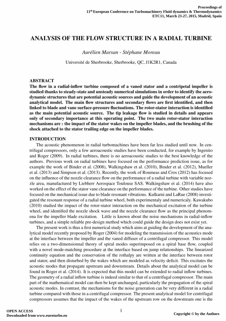
Steady-state UnsteadyCorrected rotationnal speed at the stator inlet [rpm] 49860Corrected massflow at the stator inlet [kg/s] 1.01× 10⁻¹
Total-to-total pressure ratio 3.43 3.42Isentropic total-to-total efficiency (compared with exp.) +0.02 +0.01
Table 2: Operating point of the turbine – Numerical results.
corresponds to the sound radiated by volumic sources in the flow, as shear layer in the case of a free jetfor example. Here, the study focuses on the dipole source terms only, i.e. the sound due to the surfacepressure fluctuations over the stator and rotor surfaces. Therefore the surface pressure fluctuation arestudied after the main flow structures are identified.
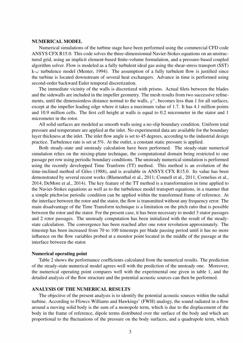
Flow topologyFigure 2 shows the steady vane and blade loading predicted by the steady-state and unsteady
numerical calculations. Steady-state and time-averaged unsteady surface pressure fields comparewell, which confirms the ability of the steady-state numerical model to predict correctly the meanperformance of the radial turbine.
A sharp increase in the static pressure is visible on the suction side of the distributor vane, sign of anormal shock wave that is attached to the trailing edge of the stator vanes. This shock in the distributoris similarly predicted by the steady-state and unsteady numerical models, as shown in figure 3. TheMach number is only smaller in the steady-state case at the impeller leading edge near the suctionside, and the shock at the impeller leading edge is weaker. This is caused by the azimutal mixing ofthe mixing plane. Yet, the Mach number in the distributor is adequately predicted by the steady-statemodel.
The influence of the tip-leakage flow is visible on the impeller blade near the shroud wall throughthe distorsion of the iso-pressure lines in figure 2. The distorsion on the pressure side of the impellervane in the trailing edge region is caused by the tip leakage vortex that accumulates along the bladepressure side, as shown by the streamlines in figure 4 calculated from seed points spread over the tipclearance and visible as black points in the figure. Both steady-state and unsteady results also show
Figure 2: Steady-loading on the rotor and stator blades.
4

(a) steady-state (b) time-averaged unsteady
Figure 3: Contours of absolute Mach number at 50% of vein height.
that part of the tip-leakage flow feeds into the tip-leakage flow of the adjacent blade.
(a) steady-state (b) time-averaged unsteady
Figure 4: Streamlines of the relative velocity flow-field passing through the tip gap.
The good agreement between the steady-state and unsteady numerical results is confirmed by thecomparison of the skin-friction patterns on the stator vane and rotor blade in Figure 5. The steady-state and time-averaged unsteady skin-friction patterns are very similar. In both cases no boundarylayer separation is visible in the distributor. Both numerical models predict that some part of the flowhitting the pressure side of the impeller blade is feeding into the tip-leakage flow and then spreadingon the suction side of the blade, near the leading edge. It then rolls into a vortex and creates a complexdetachment flow pattern. This particular behavior of the tip leakage vortex in the impeller entry zoneis bound to have some consequence on the surface pressure fluctuations. Some friction lines arehighlighted in the impeller for sake of clarity, and to stress some of the subtle slight differencesbetween the two simulations especially in the vicinity of the leading edge. Similar conclusions canbe drawn from the instantaneous skin-friction patterns, which exhibits the same flow structures. Thetime-averaged and steady skin-friction patterns are therefore both relevant.
Figure 6 shows iso-contours of the Q-criterion. This criterion is well suited for the detectionof coherent vortex in the flow, as shown by Dubief and Delcayre (2000). It is calculated from thesteady-state numerical results, the time-averaged numerical results, and one instantaneous flow field.
5

(a) Steady (b) Unsteady time-averaged
Figure 5: Skin friction pattern on stator vane and rotor blade.
The three figures reveal the same flow structures (very little unsteadiness at this design condition),identified by the following letters:
(a) Two horse-shoe vortices in the distributor, at the hub and shroud walls, which are very commonlyobserved in turbine stators. These vortices hardly reach the surface of the stator vane, and shouldthen not cause any surface pressure fluctuation on the stator vanes.
(b) A vortex shedding behind the stator-vane trailing edge, that corresponds to the stator wake whichis taken into account in the acoustic analytical model.
(c) A large tip leakage vortex in the impeller channel, which mainly originates from the leading-edge region. This vortex accumulates near the pressure side of the adjacent blade in the impellertrailing-edge region.
(d) Other vortices at the impeller leading edge, at midspan, whose location corresponds to the de-tachment pattern previously observed in the skin-friction patterns.
Figure 7 shows iso-contours of the Q-criterion in the near shroud region only, colored by the helicity,and puts into evidence the internal structure of the tip leakage flow. The tip leakage vortex (in white)originates at the impeller leading edge and is created by the flow going from the pressure side to thesuction side through the tip gap. A separation vortex (in black) corresponds to a detachment vortexthat originates at the forward upper lip of the blade tip. In a turbine, these two vortices are counter-rotating. Both migrate toward the pressure side of the adjacent blade, that they reach near the impellertrailing edge.
Tip leakage flow fieldThe tip leakage flow in a turbine develops in a particular manner compared with that in compres-
sors (Leboeuf (2009)). The effect of the relative casing motion on the growth of the tip leakage flowis indeed opposite to the effect of the driven pressure difference between the pressure side and thesuction side of the impeller vanes. In a radial turbine, that confrontation between the scrapping flow(that sticks to the casing) and the tip leakage flow field (driven by the pressure difference) defines thestructure of the tip leakage flow (Dambach et al., 1999; Dambach and Hodson, 2001). The scrappingeffect is very important in the radial part of the impeller, where the tangential speed of the blade is
6

(a) Stator - steady (b) Stator - time-averaged (c) Stator - instantaneous
(d) Rotor - steady (e) Rotor - time-averaged (f) Rotor - instantaneous
Figure 6: Iso-contours of the Q-criterion.
(a) Steady (b) Time-averaged (c) Instantaneous
Figure 7: Iso-contours of the Q-criterion in the h/H > 90% region colored by helicity (black:negative ; White: positive).
high. But this is also in that region that the tip gap is the most important compared with the smallspan-height : approximately 10% of the height of the passage. The scrapping effect then decreaseswith the radius downstream, whereas the strength of the tip leakage flow depends on the evolution ofthe tip gap along the blade and to the pressure load distribution on the blade.
For the present test case, figure 8 shows the main tip-leakage characteristics calculated in a surfacetangent to the suction side of the impeller blade over the tip gap. Figure 8-(a) shows the tip-leakagemassflow normalized by the total tip-leakage massflow rate, along the blade chord, calculated throughportions of the tip gap whose length is indicated by the width of the bars. The cumulative normalizedmassflow rate is also drawn with dark symbols. Figure 8-(b) shows the driven pressure difference,which corresponds to the pressure difference between the pressure side and the suction side overthe tip gap. Finally, figure 8-(c) shows the massflow-averaged angle of the tip-leakage flow fieldover the suction side of the blade, together with the blade tip angle (in black). The tip-leakage flowangle is taken from the azimutal direction and is positive when the tip-leakage flow is oriented toward
7

(a) Tip-leakage massflow (b) Over-tip pressure difference (c) Tip-leakage flow angle
Figure 8: Tip-leakage flow characteristics.
downstream. The blade tip angle is taken from the meridional direction, and is positive when the bladeis inclined forward compared with the rotational velocity. The evolution of the meridional abscissamR can be seen in figure 2. The evolution of the tip-leakage massflow agrees with the previousobservations about the tip-leakage vortex structure. The tip-leakage massflow is higher in the leadingedge area, mR < 0.2, where the tip-leakage vortex mainly originates. It thens decreases progressivelyunder the effect of the scrapping until mR ' 0.4, where a slight increase of the tip clearance massflowis visible. This location corresponds roughly to the origin of the separation vortex. The location ofthis separation vortex can be explained by the change in the curvature of the blade, visible in thecurve of the blade tip angle in figure 8-(c). The trace of the tip-separation vortex is visible in figure8-(b) through the slight increase of the over-tip difference around mR = 0.4. From mR = 0.4 the tipleakage massflow stabilizes, whereas the over-tip pressure difference decreases quickly. This decreaseof the over-tip pressure difference for mR > 0.4 can be explained by the decrease of the curvature ofthe blades, which can be seen in the figure 8-(c) by the flattening of the blade tip angle evolution. Nearthe trailing edge, the tip leakage massflow increases again sharply, together with a slight increase inthe over-tip pressure. This can be explained by the accumulation of the tip leakage vortex on theadjacent blade near the trailing edge, as shown previously in figure 7. Part of this tip-leakage vortex,coming from the adjacent blade, goes through the tip gap in the trailing edge region.
The tip-leakage flow angle increases all along the blade tip, which can be explained by the effectof the scrapping together with the decrease of the over-tip pressure difference. It becomes greater than90◦ from mr > 0.5 approximately, which means that the tip-leakage flow is oriented in the directionopposite to the rotational motion. The difference between the blade tip angle and the tip-leakage flowangle remains however lower than 90◦, which means that the tip-leakage flow is still flowing fromthe pressure side to the suction side of the blades. The prediction of the flow angle differs in theleading edge region between the steady-state and the unsteady time-averaged results. This differencein the flow angle can partly be explained by the influence of the mixing plane on the flow angle at theimpeller entry. The massflow-averaged value of the relative flow angle at the impeller entry predictedby the steady-state numerical simulation is 6◦ higher than the time-averaged unsteady one, due to themixing imposed by the mixing plane.
Given the stator-rotor interactions, the tip-leakage behavior is highly unsteady in the impellerentry zone. The tip-leakage massflow rate integrated over mR < 0.2 fluctuates by about 10% aroundits mean value. Then, the tip-leakage flow in the impeller entry zone behaves as an intermittent jet,which could have some significant acoustic implications.
8

Surface pressure fluctuationsThe previous section has highlighted the structure of the flow within the turbine stage. This part
of the paper focuses on the pressure fluctuations on the surface of the vanes and blades.
(a) Fundamental (BPF) (b) 1st harmonic (2BPF)
(c) 2nd harmonic (3BPF) (d) 3rd harmonic (4BPF)
Figure 9: Normalized amplitudes of the pressure harmonics by the maximum of the fundamen-tal.
Figure 9 shows the amplitude of the fundamental and the first three harmonics of the pressurefluctuations on the distributor-vane and impeller-blade surfaces. The amplitude are normalized bythe maximum of the amplitude of the fundamental. The 1st, 2nd and 3rd harmonics largely prevailover the next harmonics. This figure stresses two main areas where the amplitude of the fundamentaland the first three harmonics dominates : the distributor suction side, near the trailing edge, and theimpeller suction side, near the leading edge. The fluctuations of the surface pressure in these areas arecaused by the rotor-stator interaction, which is assumed to be the predominant source of tonal noisein the analytical model. The maximum values of the amplitudes are similar in the stator vanes and inthe rotor blades.
Pressure fluctuations are also visible further downstream on both the suction and pressure sides ofthe impeller, but mainly for the fundamental and 1st harmonics. The accumulation of the tip-leakagevortex on the pressure side of the adjacent impeller blade is visible, and generates pressure fluctuationson the impeller blade pressure side, near the tip and in the axial part. Tip-leakage vortex and othersecondary flow structures should then play a role in the noise generation, mainly for the fundamental
9
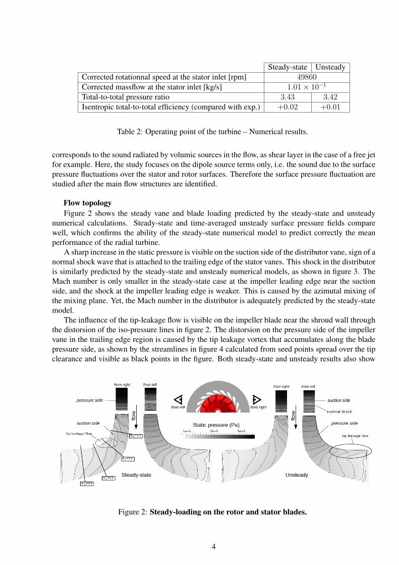
(a) Distributor suction side near trailing edge. (b) Impeller suction side near leading-edge.
Figure 10: Fluctuation of surface averaged pressure.
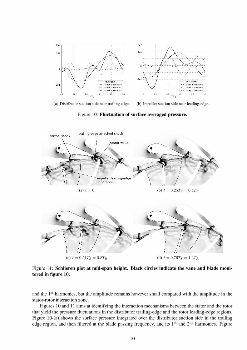
(a) t = 0 (b) t = 0.25TS = 0.4TR
(c) t = 0.51TS = 0.8TR (d) t = 0.76TS = 1.2TR
Figure 11: Schlieren plot at mid-span height. Black circles indicate the vane and blade moni-tored in figure 10.
and the 1st harmonics, but the amplitude remains however small compared with the amplitude in thestator-rotor interaction zone.
Figures 10 and 11 aims at identifying the interaction mechanisms between the stator and the rotorthat yield the pressure fluctuations in the distributor trailing-edge and the rotor leading-edge regions.Figure 10-(a) shows the surface pressure integrated over the distributor suction side in the trailingedge region, and then filtered at the blade passing frequency, and its 1st and 2nd harmonics. Figure
10

10-(b) shows the surface pressure integrated over the rotor suction side in the leading edge region,plotted as a function of time. These regions correspond to the maximum of the amplitude of thefundamental in figure 9-(a).
Figure 11 shows Schlieren plots in a midspan surface at different times, expressed as a ratio of thestator period TS and the rotor period TR respectively. The vane and blade that are monitored in figure10 are indicated by black circles. These plots highlight the normal shock accross the distributor throatwhich is visible at any times, and the shock on the other side of the distributor trailing edge, whichappears intermittently when the rotor blade passes in front of the distributor vane. The wake of thedistributor vane is also clearly visible. This figure does not allow considering the interaction betweenthe horseshoe vortex that arises from the distributor, shown in figure 6, and the impeller blades. Thiswill be studied in the future.
In figure 10-(a), the maximum of pressure for the stator is simultaneous with the maximum of thefundamental, and occurs at t/TS ' 0.8, slightly later than in figure 11-(d). This time corresponds tothe moment when the rotor passes in front of the distributor trailing edge. This generates an importantblockage, and a normal shock appears, which significantly increases the pressure on the suction sideof the vane near the trailing edge. Conversely, the minimum of the pressure occurs at t/TS ' 0.3,in the position where the blockage of the distributor outlet is minimum given the relative position ofthe two rows, as shown in figure 11-(b). Two additional local maxima of the raw pressure signal arevisible in figure 10-(a) at t/TS ' 0.1 and t/TS ' 0.5. The amplitude of the fluctuation of the 1st
pressure harmonic is low, and these maxima are only caused by the 2nd harmonic. Their origin is notyet fully understood, and further investigations have to be conducted, using for example a DynamicMode Decomposition technique.
In figure 10-(b), the maximum of pressure for the rotor occurs at t/TR ' 0.4. The relative positionof the rows at this time is shown in figure 11-(b). It corresponds to the time when the rotor bladepasses in front of the distributor vane. But the maximum of the fundamental occurs at t/TR = 0.6,which corresponds to the time intermediate between those in figures 11-(b) and 11-(c) when the bladeinteracts with the distributor wake. Thus it seems to be caused by the interaction between the rotorand the distributor wake. The maxima of the 1st harmonic occur at t/TR = 0.4 and t/TR = 0.9,and seem to be due to a combination of the interaction of the blade with the shock attached to thestator trailing edge and the interaction with the wake. The amplitude of the 2nd hamonic is muchlower. Again, further investigations should be conducted in order to conclude more precisely aboutthe respective importance of each interaction mechanism.
CONCLUSIONS AND OUTLOOKSAccording to the present study, the surface pressure fluctuations are the largest in the rotor-stator
interaction zone where unsteady phenomena in the radial inflow turbine are concentrated. This con-clusion justifies the assumption of the acoustic analytical model that the interaction between the statorand the rotor is the main acoustic source.
Yet, for the present test case and the studied operating point, this rotor-stator interaction is notonly due to the impact of the distributor wakes on the impeller blades. The shock brushing is equallyimportant. The combination between the stator wake and the shock brushing generates even order har-monics of the pressure fluctuations in the impeller. The shock brushing should therefore be integratedas a noise generation mechanism in the analytical model.
Further work will allow to clarify the importance of each interaction mechanism in terms of noisegeneration. This work will imply to study other operating points, as well as other turbines. A DynamicMode Decomposition technique in order to analyse the time-dependent numerical results could leadto some interesting conclusions.
At the studied operating point, the pressure fluctuations related to the tip-leakage flow are much
11
lower than these due to the rotor-stator interaction, and become negligible for harmonics with ordergreater than 3. It is not necessary to take the tip flow into account in the analytical model. Thisconclusion should however be challenged for other operating points, since the tip-leakage flow couldhit more severely the adjacent blade and then become a relevant acoustic source.
In addition, this study shows that the performance of the turbine and the flow structure are ad-equatly described by the mixing-plane approach, which can be used in order to investigate otheroperating points and guide the development of the analytical model.
ACKNOWLEDGEMENTSThe present work is part of a research project in collaboration between the Universite de Sher-
brooke, the LMFA of the Ecole Centrale de Lyon, and Liebherr-Aerospace Toulouse SAS (LTS). Theauthors thank LTS for their financial support, especially Johanna Ingenito who is in charge of theproject. The help of Thorsten Hansen (ANSYS Germany) has been really valuable. Thank also toMarlene Sanjose (Universite de Sherbrooke) and Michel Roger (Ecole Centrale de Lyon).
REFERENCESBinder, N., Carbonneau, X., and Chassaing, P. Off-design considerations through the properties of
some pressure-ratio line of radial inflow turbines. International Journal of Rotating Machinery,2008.
Binder, N., Le Guyader, S., and Carbonneau, X. Analysis of the variable geometry effect in radialturbines. Journal of Turbomachinery, 134, 2012.
Blumenthal, R., Hutchinson, B., and Zori, L. Investigation of transient CFD methods applied toa transonic compressor stage. In Proceedings of ASME Turbo Expo 2011. Vancouver, BritishColumbia, Canada, 2011.
Connell, S., Braaten, M., Zori, L., Steed, R., Hutchinson, B., and Cox, G. A comparison of advancednumerical techniques to model transient flow in turbomachinery blade rows. In Proceedings ofASME Turbo Expo 2011. Vancouver, British Columbia, Canada, 2011.
Cornelius, C., Biesinger, T., Zori, L., Campregher, R., Galpin, P., and Braune, A. Efficient timeresolved multistage CFD analysis applied to axial compressors. In Proceedings of ASME TurboExpo 2014. Dusseldorf, Germany., 2014.
Dambach, R. and Hodson, H.P. Tip leakage flow in a radial inflow turbine with varying gap height.Journal of Propulsion and Power, 17(3):644–650, 2001.
Dambach, R., Huntsman, I., and Hodson, H.P. 1998 turbomachinery committee best paper award:An experimental study of tip clearance flow in a radial inflow turbine. Journal of Turbomachinery,121, 1999.
DeMore, D., Maghsoudi, E., Pacheco, J., Sorokes, J., Hutchinson, B., Holmes, W., Lobo, B., andVashistha, V. Investigation of efficient CFD methods for rotating stall prediction in a centrifugalcompressor stage. In Proceedings of ASME Turbo Expo 2014. Dusseldorf, Germany., 2014.
Dubief, Y. and Delcayre, F. On coherent-vortex identification in turbulence. Journal of Turbulence,1, 2000.
Fukano, T. and Jang, C.M. Tip clearance noise of axial flow fans operating at design and off-designcondition. Journal of Sound and Vibration, 275(35):1027–1050, 2004.
12

Giles, M. Calculation of unsteady wake/rotor interaction. Journal of Propulsion and Power, 4(4),1988.
Ingenito, J. and Roger, M. Measurement and prediction of the tonal noise of a centrifugal compressorat inlet. In 15th AIAA/CEAS Aeroacoustics Conference (30th AIAA Aeroacoustics Conference).Miami, Floride, 2009.
Kawakubo, T. Unsteady rotor-stator interaction of a radial-inflow turbine with variable nozzle vanes.In Proceedings of ASME Turbo Expo 2010., pages 2075–2084. Glasgow, UK, 2010.
Kulkarni, A. and LaRue, G. Vibratory response characterization of a radial turbine wheel for auto-motive turbocharger application. In Proceedings of ASME Turbo Expo 2008: Power for Land, Seaand Air, pages 583–591. Berlin, Germany, 2008.
Leboeuf, F. Ecoulements 3D dans les turbomachines. Ecole Centrale de Lyon, 2009.
Menter, F.R. Two-equation eddy-viscosity turbulence models for engineering applications. AIAAJournal, 32(8), 1994.
Mueller, L., Alsalihi, Z., and Verstraete, T. Multidisciplinary optimization of a turbocharger radialturbine. Journal of Turbomachinery, 135, 2013.
Roger, M. Analytical modelling of wake-interaction noise in centrifugal compressors with vaneddiffusers. In 10th AIAA/CEAS Aeroacoustics Conference. Manchester, UK., 2004.
Roger, M., Moreau, S., and Marsan, A. Generation and transmission of spiral acoustic waves inmulti-stage subsonic radial compressors. In 20th AIAA/CEAS Aeroacoustics Conference. Atlanta,GA, United States., 2014.
Roumeas, M. and Cros, S. Aerodynamic investigation of a nozzle clearance effect on radial turbineperformance. In ASME Turbo Expo 2012: Turbine Technical Conference and Exposition. Copen-hagen, Denmark, 2012.
Simpson, A.T., Spence, S.W.T., and Watterson, J.K. Numerical and experimental study of the per-formance effects of varying vaneless space and vane solidity in radial turbine stators. Journal ofTurbomachinery, 135, 2013.
Walkingshaw, J., Spence, S., Ehrhard, J., and Thornhill, D. A numerical study of the flow fields in ahighly off-design variable geometry turbine. In Proceedings of ASME Turbo Expo 2010: Power forLand, Sea and Air, pages 1951–1960. Glasgow, UK, 2010.
Walkingshaw, J., Spence, S., Ehrhard, J., and Thornhill, D. An experimental assessment of the effectsof stator vane tip clearance location and back swept blading on an automotive variable geometryturbocharger. Journal of Turbomachinery, 136, 2014.
13