analysis of the suspension beam in accelerometer for ... · a euler-bernoulli beam theory...
TRANSCRIPT

ANALYSIS OF THE SUSPENSION BEAM IN ACCELEROMETER FOR STIFFNESS CONSTANT AND RESONANT FREQUENCY BY USING
ANALYTICAL AND NUMERICAL INVESTIGATION
WONG WAI CHI
UNIVERSITI SAINS MALAYSIA
2007
ANALYSIS OF THE SUSPENSION BEAM IN ACCELEROMETER FOR STIFFNESS CONSTANT AND RESONANT FREQUENCY BY USING
ANALYTICAL AND NUMERICAL INVESTIGATION
by
WONG WAI CHI
Thesis submitted in fulfillment of the requirements for the degree
of Master of Science
June 2007
ACKNOWLEDGEMENTS
First of all, I would like to express my deepest gratitude to my family for their patience,
understanding and support. Their supports allowed me to concentrate fully in my
studies without hesitation. I would also like to express my sincere thanks to my
supervisor, Assoc. Prof. Dr. Ishak Hj. Abd. Azid for his tremendous guidance, advice,
support, assistance and encouragement throughout my postgraduate candidature
period. Without him, I would not been able to complete my research in such an efficient
manner. I would also like express my appreciation to my co-supervisor Prof. Dr.
Burhanuddin Yeop Majlis, who allows me to study at the MEMS fabrication laboratory
at IMEN, UKM and give me a chance to explore the fabrication process.
Apart from them, I would like to forward special thanks to my fellow colleagues
Mr. Lee Hing Wah, Mr. Gyanaprakash, Mr. Ezral, Mr. Lim Mook Tzeng, Mr. Rosmaini,
Mr. Khairul Anuar, Mr. Shahrizan, Mr. Chuah Hun Guan and Ms. Ko Ying Hao for their
moral supports and help especially during the initial stage of my research. Thanks are
also to all students and staff of Universiti Sains Malaysia, those who helped me either
directly or indirectly in completing my research.
I am gratitude to Universiti Sains Malaysia for awarding me the GRADUTE
ASSISTANT SCHEME scholarship which relieved me of financial insecurity. Last but
not least, my sincere thanks, compliments and regards to anyone who had helped and
supported me in one way or another.
WONG WAI CHI
June 2007
ii
TABLE OF CONTENTS
Page ACKNOWLEDGEMENTS ii
TABLE OF CONTENTS iii
LIST OF TABLES viii
LIST OF FIGURES x
LIST OF SYMBOLS xii
LIST OF APPENDICES xv
LIST OF PUBLICATIONS & SEMINARS xv
ABSTRAK xvi
ABSTRACT xvii
CHAPTER ONE : INTRODUCTION 1
1.0 Overview
1.1 Introduction to micro-accelerometer
1.1.1 Short history of MEMS
1.1.2 MEMS sensing device
1.1.3 Micro-accelerometer
1.2 Structural analysis of micro-accelerometer
1.3 Finite element method
1.4 Neuro-genetic optimization
1.4.1 Artificial neural network (ANN)
1.4.2 Genetic algorithm (GA)
1.5 Problem definition
1.6 Thesis objectives
1.7 Thesis outline
1
1
1
2
3
4
5
5
5
6
6
7
7
iii
CHAPTER TWO : LITERATURE SURVEY 9
2.0 Overview
2.1 Micro-accelerometer
2.1.1 The evolvement of micro-accelerometer
2.1.2 Capacitance accelerometer as the most successful
type of micro-accelerometer
2.1.3 Micro-accelerometer in market – the important of
accelerometer
2.1.4 The characteristic of micro-accelerometer
2.2 Stiffness constant and resonant frequency in MEMS device
2.2.1 Stiffness constant and resonant frequency in Micro-
accelerometer
2.2.2 Stiffness constant and resonant frequency in comb
finger type device
2.3 Finite element analysis (FEA)
2.3.1 Finite element simulation of accelerometer
2.3.2 Finite element simulation with ANSYS®
2.4 Optimization of accelerometer design
2.5 Summary
9
9
9
10
10
11
12
12
14
16
16
17
18
19
CHAPTER THREE : ANALYTICAL AND NUMERICAL
FORMULATIONS
21
3.0 Overview
3.1 Working mechanism of comb finger type accelerometer
3.2 Several design models of suspension beams
3.3 Equivalent stiffness constant in spring mass model
21
21
24
24
iv

3.4 Analytical derivations of the effective stiffness constant and
effective mass for suspension beam in accelerometer
3.4.1 General formulations for fixed-fixed beam
3.4.2 Effective stiffness constant of straight fixed-fixed beam
3.4.3 Effective stiffness constant of crab-leg beam
3.4.4 Effective stiffness constant of folded beam
3.4.5 Effective stiffness constant of round folded beam
3.4.6 Effective mass
3.4.7 Summary of the determined stiffness constant and
effective mass
3.5 Finite Element Formulations
3.5.1 Beam element formulations
3.5.2 Computer code for solving the finite element
formulations
3.6 Finite element modeling with ANSYS
3.6.1 ANSYS® simulation methodology
3.6.2 Preprocessing
3.6.3 Solution and postprocessing
3.7 Neuro-genetic optimization
3.7.1 Artificial neural network (ANN)
3.7.2 Genetic algorithm (GA)
3.8 Summary
26
26
30
32
36
40
45
48
50
50
54
57
57
58
63
63
63
65
66
CHAPTER FOUR : RESULT AND DISCUSSION 67
4.0 Overview
4.1 Verification of the current model by using ANSYS®
4.1.1 Stiffness constant and resonant frequency
67
67
69
v
4.1.2 Cross axis sensitivity and shock analysis
4.2 Different design types of suspension beam
4.3 Comparison results by different approaches
4.3.1 Comparison with other researchers
4.3.2 Comparison results between analytical and finite
element formulation
4.3.3 Comparison results between analytical and finite
element and FEA software for beam model
4.3.4 Comparison results between analysis on beam model
and complete device by using ANSYS
4.3.5 Comparison results between analytical result and
simulation result with complete model
4.4 Analysis on different suspension beam designs
4.5 Parametric Study
4.5.1 Parametric study on device dimensions
4.5.2 Parametric study on folded beam
4.6 Neuro-genetic optimization
4.6.1 Artificial neural network (ANN)
4.6.2 Genetic algorithm (GA)
4.7 Summary
71
73
75
75
76
77
79
81
83
84
84
85
87
87
89
90
CHAPTER FIVE : CONCLUSION 92
5.0 Conclusion 92
5.1 Recommendation for Future Work 93
BIBLIOGRAPHY 95
vi

APPENDICES 98
Appendix A: Euler-Bernoulli beam theory assumptions 99
Appendix B: Stiffness constant of Fixed-fixed Beam 100
Appendix C: Training input for ANN 104
PUBLICATIONS LIST 106
vii
LIST OF TABLES
Page
2.1 Summary of the literature review 20
3.1 The coordinates of main nodes 55
3.2 Device parameters 58
3.3 Mechanical conversion factors for MKS to µMKSV 59
3.4 Summary of the characteristics of the SOLID186 and BEAM3
element
60
3.5 Material properties for accelerometer 60
3.6 Architecture of the ANN 65
4.1 Input parameters of accelerometer 68
4.2 Result of parametric investigations 70
4.3 Comparison of result between simulation result and Chae et al.
(2000) for displacement under different acceleration
72
4.4 Comparison of result between simulation result and Chae et al.
(2000) for maximum stress under external shock
72
4.5 The suspension beam design and its dimension 74
4.6 Comparison results for stiffness constants between ANSYS®
simulation, finite element simulation (FE), analytical and
literatures
75
4.7 Comparison of result for the effective stiffness constant and the
effective mass between determinations of analytical, finite
element (MATLAB)
77
4.8 Comparison of result for the effective stiffness constant of
analytical, finite element (MATLAB) and FEA software
(ANSYS) with difference meshing
78
viii
4.9 Comparison of result for stiffness constant between beam only
and the complete device
80
4.10 Comparison of stiffness constant, effective mass and resonant
frequency between analytical result and simulation (ANSYS)
result
82
4.11 The resonant frequency of difference design 84
4.12 Parametric study on device dimension 85
4.13 Parametric study on folded beam 86
4.14 Data points ranges for ANN 88
4.15 Comparison of results between ANN predictions and ANSYS®
simulations for variations in device parameters
89
4.16 Optimized parameters obtained using GA 90
ix
LIST OF FIGURES
Page
1.1 Typical design of microaccelerometer 3
3.1 Typical design of comb finger type accelerometer 22
3.2 Schematic arrangement of accelerometer 23
3.3 The physical meaning of dimension of a comb finger type
accelerometer
23
3.4 Different suspension beam design model in accelerometer for
analysis
24
3.5 Free body diagram of typical arrangement of an accelerometer 25
3.6 Fixed-fixed beam 27
3.7 Straight beam 30
3.8 Crab-leg beam 32
3.9 Resolved components of crab-leg beams 33
3.10 Folded beam 36
3.11 Resolved components of folded beam 37
3.12 Round folded beam 40
3.13 Resolved components of round folded beam 41
3.14 Free body diagram for the second component of round folded
beam
42
3.15 Transverse forces at a ring 42
3.16 The elastic behavior of a member subjected to axial loading 50
3.17 Beam element 51
3.18 Frame element 51
3.19 Frame angle 53
3.20 GUI interface for frame analysis 56
3.21 Typical dimension of an accelerometer 57
x

3.22 Meshed model of folded beam 61
3.23 Meshed model of a typical accelerometer 61
3.24 Boundary condition on accelerometer model 63
3.25 Neural Networks training process 64
4.1 Dimensions of an accelerometer 68
4.2 Stress distribution under external shock 73
4.3 Design shape 74
xi
LIST OF SYMBOLS
Symbol Description Unit
a Acceleration µm/s2
A Area µm2
c Cosine -
d Distance µm
d0 Sensing gap µm
d1 µm
E Young’s modulus MPa , µN/µm2
f Force µN
fr Resonant frequency kHz
frcal Calculated resonant frequency kHz
frsim Simulated resonant frequency kHz
g Gravity acceleration µm/s2
G Shear modulus MPa , µN/µm2
I Moment of inertia µm4
k Stiffness constant µN/µm
k1/4 Stiffness constant of quarter model µN/µm
kbm Stiffness constant due to bending moment µN/µm
kcal Calculated stiffness constant µN/µm
keff Effective stiffness constant µN/µm
kfixed Stiffness constant of fixed-fixed beam µN/µm
ks Stiffness constant due to shear µN/µm
ksim Simulated stiffness constant µN/µm
L Length µm
xii
lbeam Length of suspension beam µm
lfinger Length of finger µm
lproof mass Length of proof mass µm
lr Length of second component µm
M Mass Kg
meff Effective mass Kg
M Moment µN·µm
N Number of finger Pair
N Shape function -
R Radius µm
R Reaction force µN
Ra Axial force µN
S Sine -
S shear deflection constant -
T Thickness µm
u, v, w Displacement of x, y, z direction respectively -
U Internal work / strain energy pJ ,
µN·µm
V Volume µm3
W Width µm
wbeam Width of suspension beam µm
wfinger Width of finger µm
wi weighting function -
wproof mass Width of proof mass µm
wr Width of second component µm
W External work pJ ,
xiii
µN·µm
x, y, z Local coordinates µm
X, Y, Z Global coordinates
δ Deflection / displacement µm
ε Strain µm/µm
φ Angle rad
γ Shear strain µm/µm
µ Poisson's ratio -
θ Slope, rotation rad
ρ Density kg/µm3
σ Stress MPa , µN/µm2
τ shear stress MPa , µN/µm2
xiv
LIST OF APPENDICES Page
A Euler-Bernoulli beam theory assumptions 99
B Stiffness constant of fixed-fixed Beam 100
C Training input for ANN 104
LIST OF PUBLICATIONS
Page
1 Creep Analysis of Bimaterial Microcantilever Beam for Sensing
Device Using Artificial Neural Network (ANN)
107
2 Analysis of Comb Finger Type Capacitive Accelerometer
Performance by Using FEM Modeling
108
3 Stiffness and Frequency Analysis of Microaccelerometer 109
xv

ANALISIS KE ATAS RUSUK AMPAIAN DALAM METER PECUT BAGI PEKALI KEKUKUHAN DAN FREKUENSI RESONANSS SECARA
PENYIASATAN ANALISIS DAN BERANGKA
ABSTRAK
Mikro-meterpecut yang digunakan dalam pelbagai penerapan hanya akan tercapai
dengan jayanya sekiranya keperluan frekuensi resonans dan kepekaan dapat dipenuhi
dan konsisten. Berdasarkan syarat-syarat tersebut, analisis struktur pada pekali
kekukuhan and frekuensi resonans bagi rasuk ampaian dalam meter pecut dan
seterusnya pengoptimuman kepada kepekaan haruslah dilakukan. Dengan itu,
beranalisis berasal pada teori dan menggunakan kaedah unsur terhingga (FEM) telah
dihasilkan dengan memberikan tumpuan ke atas ampaian rasuk meterpecut. Selain
daripada itu, analisis unsur terhingga (FEA) tiga dimensi telah dihasilkan untuk
menganalisis pekali kekukuhan and frekuensi resonans bagi mikro meterpecut jenis
comb finger. Bagi FEA, terdapat dua jenis model yang digunakan iaitu model terperinci
dan model rasuk. Bagi model rasuk, dua jenis jaringan telah dilakukan, iaitu jaringan
terkawal and jaringan bebas. Enam jenis ampaian rasuk telah dianalisis dengan
kaedah yang disebutkan. Ramalan bagi pekali kekukuhan and frekuensi resonans
dengan cara beranalisis menunjukkan sedikit berbazean dengan ramalan yang
diperolehi melalui simulasi FEA ANSYS® dalam julat 0-10%. Perbandingan keputusan
bagi pekali kekukuhan and frekuensi resonans yang diperolehi melalui simulasi FEA
ANSYS® dengan keputusan sediaada juga memuaskan, iaitu tiada berbezaan dalam
ramalan frekuensi resonans dan hanya 0.59% berbezaan dalam ramalan pekali
kekukuhan. Kepercayaan FEA ANSYS® dalam analisis memberikan penggalakan bagi
melanjukkan analisis atas prestasi meterpecut dengan berbagai geometri and reka
bentuk ampaian rasuk. Kajian ini juga telah memperkenalkan suatu reka bentuk
optimum dengan menggunakan kaedah pengoptimuman Neuro-Genetic yang
menggabungkan aplikasi Rangkaian Neural Tiruan (ANN) dan Algoritma Genetik (GA).
xvi

ANALYSIS OF THE SUSPENSION BEAM IN ACCELEROMETER FOR STIFFNESS CONSTANT AND RESONANT FREQUENCY BY USING
ANALYTICAL AND NUMERICAL INVESTIGATION
ABSTRACT
A successful and consistent performance of micro-accelerometer which has been
applied in various applications can only be achieved when the resonant frequency and
the sensitivity requirement are fulfilled. In view of this, structural analysis on stiffness
constant and resonant frequency for the suspension beam in accelerometer, and
subsequently optimization design of accelerometer with respect to sensitivity in term of
displacement against acceleration must be performed. For that reason, a two-
dimensional analytical formulation derived theoretically and numerically by using finite
element method (FEM) has been developed with the focus on the suspension beam of
micro-accelerometer. Apart from that, a three-dimensional finite element analysis (FEA)
has been simulated by using ANSYS to analyze the stiffness constant and the resonant
frequency of the comb finger type capacitive micro-accelerometer. For the FEA, two
types of modeling, namely the complete model and the beam model, have been used.
The beam models have been discretized in two different ways, namely mapped mesh
and free mesh. Six types of suspension beam have been analyzed. The prediction of
stiffness constant and resonant frequency obtained using ANSYS® FEA shows slight
difference compared to that obtained analytically with 0-10% difference. The stiffness
constant and resonant frequency obtained using ANSYS® FEA shows a good
agreement with the published results where the resonance frequency achieves zero
difference and only 0.59% difference in stiffness constant. The success of the ANSYS®
FEA model provides further encouragement in using the model to analyze the
performance of the device for various combinations of geometry and different design in
suspension beam. An optimized design of accelerometer is then obtained by using
Neuro-Genetic optimization which combined the artificial neural network (ANN) and
genetic algorithms (GA).
xvii
CHAPTER 1 INTRODUCTION
1.0 Overview
An introduction to the micro-accelerometer, the analysis and optimizing method,
along with the problem definition, the objectives and the outline of the thesis will be
presented. The main contents in this chapter are:
• Introduction to micro-accelerometer
• Structural analysis of micro-accelerometer
• Finite element method
• Neuro-genetic optimization
• Problem definition
• Thesis objective
• Thesis outline
1.1 Introduction to micro-accelerometer
1.1.1 Short history of MEMS
Micro-electromechanical systems (MEMS) can be described as a device where
a mechanical function is coupled with an electrical signal and combined with other
physical domains. Normally MEMS refer to a collection of microsensors and actuators
which can sense their environment and have the ability to react to the changes in that
environment with the use of a microcircuit control. MEMS are also referred to as
micromechanics, micro machines, or Micro Systems Technology (MST). The
dimension of MEMS and their components are from 100 nanometers to centimeter
range. MEMS make product faster, smaller, lighter, more reliable, cheaper, and are
capable of incorporating more complex functions and are usually more precise while
maintaining the production cost at low level.
1
Richard Feynman was the first person to say or "predict" about MEMS on
December 29th 1959. However, MEMS only emerged in the beginning of 1990s, with
the aid of the development of integrated circuit (IC) fabrication processes, in which
sensors, actuators, and control functions are co-fabricated in silicon. Since then,
remarkable research progresses have been achieved in MEMS. Nowadays, MEMS
devices include somehow less integrated devices, such as micro-accelerometers, inkjet
printer head, and micro-mirrors for projection. The concepts and feasibility of more
complex MEMS devices have been proposed and demonstrated for applications in
various fields such as micro-fluidics, aerospace, biomedical, chemical analysis,
wireless communications, data storage, display, and optics.
Mechanical behavior and mechanical response of those devices play major role
in their performance. The behaviors of MEMS devices can be studied using numerical
computing, analysis (fundamental theories) and experiments.
1.1.2 MEMS sensing device
Sensors are one of the main functionality of MEMS. Normally, the working
principle of mechanical sensors (except a certain class of flow sensors) relies on the
mechanical deformation of a construction (deflection of a membrane or a mass
suspended by a beam). This deformation will then be translated into an electrical signal
for presentation. The sensors need a reproducible signal which means that the
structure must deform under an equal load in the same way.
The mechanical deformation due to mechanical forces can be measured in a
number of ways. The measurement can be due to changes of the electrical resistance
because of geometric changes of resistors or strain in the resistors (piezoelectricity),
changes of electrical capacitance, changes in the resonant frequency of vibrating
elements in the structure and changes of optical resonance.
2
1.1.3 Micro-accelerometer
Micro-accelerometers or accelerometer are one of the most important types of
MEMS device, which have the second largest sales volume after pressure sensors
(Yazdi et al. 1998). The large volume demand for MEMS accelerometers are due to
their capability to be used in variety of applications. They can be used to measure tilt,
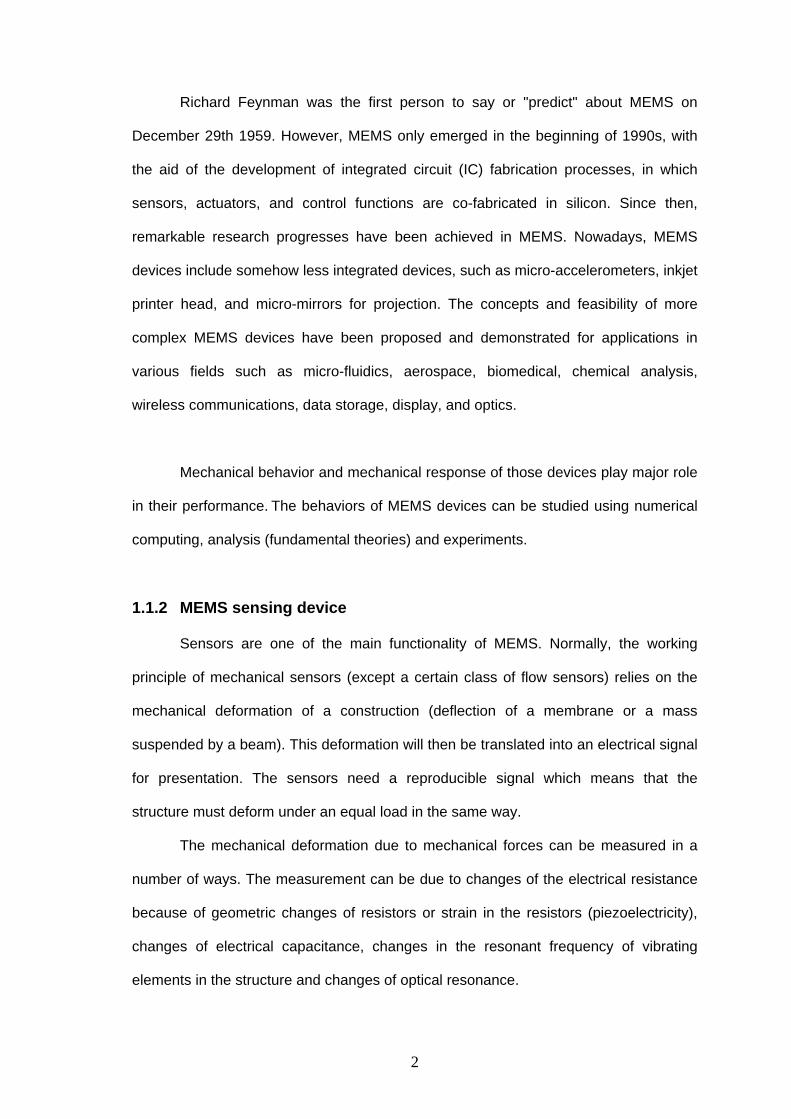
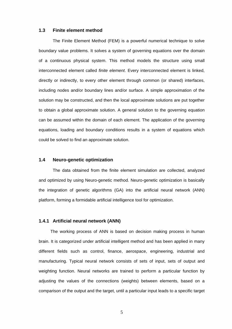
motion, position, vibration and shock. Generally, accelerometer consists of a proof
mass either seismic mass or comb finger suspended by compliant beams anchored to
a fixed frame, as shown in Figure 1.1. The operation can be modeled by a second-
order mass-damper-spring system. External acceleration can be measured by relative
displacement (capacitance) or suspension-beam stress (piezoresistive).
(a) Seismic mass device (b) Comb finger device Figure 1.1: Typical design of microaccelerometer
Recently, attention has been focused on the modeling and analysis on the
sensitivity and the mechanical performances of comb finger devices. The comb finger
type devices are one of the most important building blocks of MEMS due to their high
sensitivity and high performance. Comb finger devices can be applied as either MEMS
sensors or MEMS actuators. MEMS sensors normally sense the physical environment
by means of mechanical sense and giving the output in electrical means. Comb finger
type sensors have been used in air-bag system, chassis control, side-impact detection,
antilock braking system, machinery vibration monitoring, inertial navigation, seismology
and mouse. On the other hand, the MEMS actuators respond to the electronic
commands and actuate the dynamic system. Comb driven actuators include RF
3
resonators, electromechanical filters, optical MEMS, microgrippers, gyroscopes and
voltmeters. They have also been used to drive vibromotors and micromechanical gears.
1.2 Structural analysis of micro-accelerometer
In general, for the design of a MEMS device with moving parts, the analysis
usually starts with structural analysis and vibration analysis. Stiffness constant and
subsequently resonant frequency are two important parameters which must be
determined before other analyses can be carried out. Stiffness constant, which is an
important intermediate parameter in the determination of natural frequency and
sensitivity, is determined from a combination of physical geometrical parameters and
material properties. In contrast, resonant frequency characterizes the bandwidth as
well as the physical sensitivity of the accelerometer.
The sensitivity of the accelerometer is a measure of displacement with respect
to acceleration. It is determined from the stiffness constant and the effective mass of
the accelerometer. The resonant frequency is also determined from the effective
stiffness constant and the effective mass. The relationship between sensitivity and
resonant frequency with the stiffness constant and the effective mass is given in
Equations 1.1 and 1.2.
km
aaccerationntdisplacemeySensitivit eff===
δ (1.1)
effnr m
kf == ωπ2 (1.2)
where fr is the natural frequency or resonant frequency, ωn is the natural circular
frequency, k is the stiffness constant, and meff is the effective mass.
4
1.3 Finite element method
The Finite Element Method (FEM) is a powerful numerical technique to solve
boundary value problems. It solves a system of governing equations over the domain
of a continuous physical system. This method models the structure using small
interconnected element called finite element. Every interconnected element is linked,
directly or indirectly, to every other element through common (or shared) interfaces,
including nodes and/or boundary lines and/or surface. A simple approximation of the
solution may be constructed, and then the local approximate solutions are put together
to obtain a global approximate solution. A general solution to the governing equation
can be assumed within the domain of each element. The application of the governing
equations, loading and boundary conditions results in a system of equations which
could be solved to find an approximate solution.
1.4 Neuro-genetic optimization
The data obtained from the finite element simulation are collected, analyzed
and optimized by using Neuro-genetic method. Neuro-genetic optimization is basically
the integration of genetic algorithms (GA) into the artificial neural network (ANN)
platform, forming a formidable artificial intelligence tool for optimization.
1.4.1 Artificial neural network (ANN)
The working process of ANN is based on decision making process in human
brain. It is categorized under artificial intelligent method and has been applied in many
different fields such as control, finance, aerospace, engineering, industrial and
manufacturing. Typical neural network consists of sets of input, sets of output and
weighting function. Neural networks are trained to perform a particular function by
adjusting the values of the connections (weights) between elements, based on a
comparison of the output and the target, until a particular input leads to a specific target
5
output. Once the network is trained, it can then be fed with any unknown input and is
expected to predict the output with a high degree of accuracy.
1.4.2 Genetic algorithm (GA)
Once a well trained ANN via FEA is obtained, it is then combined with GA to
form a tool for search and optimization purposes. Genetic Algorithms (GA) are adaptive
search methods based on natural selection of survival of the fittest and natural
genetics. They combine survival of the fittest among string structures with a structured
yet randomized information exchange to form a search algorithm with some of the
innovative flair of human search. GA exploits the fittest traits of old individuals to create
a new generation of artificial creatures (strings). With each generation, a better
population of individuals is created to replace the old population. Based on these
principles, genetic algorithm is developed as a search tool that efficiently exploits
historical information to speculate on new search points with expected improved
performance.
1.5 Problem definition
The comb finger type is the most successful and effective type capacitive
accelerometer. Resonant frequency and stiffness constant, which values depend
mostly on the structural design of comb finger type accelerometer especially the
suspension beam design, are two important parameters in the performance analysis of
accelerometer. However, the study on the structural analysis of suspension beam in
comb finger type accelerometer is not yet well established. The analytical derivation for
these two parameters is only available for simple design such as straight beam. The
formulae for stiffness constant and effective mass for folded beam and crab-leg beam,
which are two common designs in suspension beam of MEMS devices (sensors and
actuators), are either too simple or too complicated. The formula for stiffness constant
6

and effective mass should be derived so that the performance of the accelerometer can
be analyzed for common designs in suspension beam of comb finger type
accelerometer. However, when the solution is obtained analytically, specific formulae
need to be derived for each and every different design. Thus, this is tedious and time
consuming. Therefore, a numerical solution which is applicable to all types of design for
suspension beam needs to be developed.
1.6 Thesis objectives
For this project of “Analysis of the Suspension Beam in Accelerometer for
Stiffness Contant and Resonant Frequency by Using Analytical Solution and Numerical
Investigation”, there are four objectives to be achieved. They are:
• To analyze the performance of comb finger type capacitive accelerometer based on
stiffness constant and resonant frequency.
• To develop analytical model to predict the stiffness constant and the effective mass
of the suspension beam for comb finger type capacitive accelerometer.
• To develop a reliable finite element models to predict the stiffness constant, the
effective mass and the resonant frequency of the suspension beam for comb finger
type capacitive accelerometer.
• To optimize the design of the suspension beam for comb finger type capacitive
accelerometer by using Neuro-Genetic methodology.
1.7 Thesis outline
The thesis is presented in five chapters which include introduction, literature
survey, analytical and numerical formulations, results and discussion and finally
conclusion. The first chapter gives a brief introduction on the micro-accelerometer with
an overview on the comb finger type accelerometer and analyses that are required to
7
be conducted. The objectives of the project are also presented in this chapter. In
chapter two, a literature survey regarding micro-accelerometer, stiffness constant in
micro-accelerometer, and the analysis using finite element simulation will be presented.
This chapter deals with the past and current trends in the modeling and analysis of the
micro-accelerometer. Working mechanism of comb finger type accelerometer, several
design models of suspension beams, and determination of the device performance by
using analytical, numerical and FEA analysis will be described in chapter three. Results
from chapter three are presented and discussed in chapter four. Finally, the thesis will
end with conclusions in chapter five.
8
CHAPTER 2 LITERATURE SURVEY
2.0 Overview
Literature reviews for four main scopes of the thesis are presented in this
section. The scopes covered are shown as below:
• Micro-accelerometer
• Stiffness constant and resonant frequency in MEMS device
• Finite element simulation
• Optimization of accelerometer design
2.1 Micro-accelerometer
2.1.1 The evolvement of micro-accelerometer
According to Bernstein (2003), accelerometers are the starts of the MEMS
show and currently still the leader in commercially successful MEMS technology. Yazdi
et al. (1998) stated that the micro-accelerometers which have low-cost, small-size,
high-performance open up new markets opportunities, and enhance the overall
accuracy and performance of the systems consisting of micro-accelerometers.
Throughout the innovation of micro-accelerometer, some popular suspension support
designs have been suggested, including cantilever support, crab-leg/folded-beam
configuration, and symmetric full-bridge supports. The physical mechanisms underlying
MEMS accelerometers have moved from the traditional piezoresistive to capacitive,
tunneling, resonant, thermal, and others which are not popular but feasible such as
piezoelectric, optical, and electromagnetic.
9
2.1.2 Capacitance accelerometer as the most successful type of micro-
accelerometer
Both of the review papers (Bernstein, 2003 and Yazdi et al., 1998) agreed that
capacitive transduction is the most successful type. Its application varies from low-cost,
large-volume automotive accelerometers, to high-precision inertial-grade microgravity
devices since capacitive sensor has high sensitivity, stable dc-characteristics, low drift,
low power dissipation, low temperature sensitivity, higher bandwidth, the simplicity of
the sensor element itself, and no requirement for exotic materials. Yazdi et al. (1998)
pointed out the disadvantage of capacitive devices which can be susceptible to
electromagnetic interference (EMI), as their sense node has high impedance. However,
this problem can be addressed by proper packaging and shielding the accelerometer
and its interface circuit. Bernstein (2003) stated that the output of capacitance device
can be analog, digital, ratiometric to the supply voltage, or any of various types of pulse
modulation. Sensors with digital output are convenient when the data transmitted are
without further noise degradation.
2.1.3 Micro-accelerometer in market – the important of accelerometer
Yole Développement (2006) reported that acceleration sensors have been
widely used in the automotive industry for more than 30 years as motion sensing is
essential for safety functions. But the real development of this market started only in
1988 when the first silicon accelerometer is used for airbag applications. The total
accelerometer market value has been estimated to be $393 million in 2005 and $869
million in 2010 for a production of 161M and 502M units respectively. It is estimated
that the automotive field accounts for 89% of the total volume which represents 81% of
the global market value. 140 million accelerometers will be required in 2006 for the
automotive field only.
10
Clifford (2004) forecasted that more than 100 accelerometer applications would
be established soon, from PC peripherals to home networking to security, since
accelerometer can measure tilt, motion, position, vibration, and shock. The major
application of accelerometer is automotive applications; other applications area include
biomedical applications, numerous consumers’ applications, industrial applications and
so on. High-sensitivity accelerometers are crucial components in self-contained
navigation and guidance systems, seismometry for oil exploration and earthquake
prediction, and microgravity measurements and platform stabilization in space.
2.1.4 The characteristic of micro-accelerometer
Among the specifications to be considered when choosing micro-accelerometer
are output/input sensitivity, bandwidth, frequency response, resolution, noise floor, drift,
linearity, dynamic range, offset, cross-axis sensitivity, shock survivability and power
consumption. Yazdi et al. (1998) wrote that the challenges and future trends of micro-
accelerometer is the development of low-cost, high sensitivity, low noise level, and
large dynamic range, low-stress and low-drift packaging technologies, inertial-grade
accelerometers with sub-µg noise levels, good long-term stability, and low temperature
sensitivity. Bernstein (2003) suggested that high-g accelerometers is a niche market for
accelerometers that read out very high g for crash tests, impacts, and missile and
artillery shell launches.
Yazdi et al. (1998) suggested that generally, the design flow of accelerometer
starting with describing stiffness constant (K) as a function of device geometry by using
formulas, and then performing final design, by simulation and optimization by software.
Bernstein (2003) stated that the resonant frequency is also important to determine the
sensors upper useful frequency range, its sensitivity and displacement per g of
acceleration.
11
2.2 Stiffness constant and resonant frequency in MEMS device
Stiffness constant and resonant frequency, which are the topics of this research,
are two of the most important functionality that will be required in design of any MEMS
devices with moving parts. Sensors and actuators, in particular, often require specific
stiffness constant and resonant frequency to guarantee successful and repeatable
performance.
2.2.1 Stiffness constant and resonant frequency in micro-accelerometer
The simplest design of micro-accelerometer is a proof mass suspended by a
cantilever. The research on cantilever support piezoresistive accelerometer can be
traced back to year 1979 (Yazdi et al., 1998) in which this design is one of the simplest
designs of accelerometer. Even for this simple design, the stiffness constant and the
resonant frequency are always the interest in research. Those parameters are
important in both piezoresistive and capacitive accelerometer. Kovács et al. (2000)
have analyzed the lowest resonant frequency, which characterized the bandwidth as
well as the physical sensitivity, of cantilever- and bridge-type monolithic piezoresistive
and capacitive accelerometers. The derivations have been carried out by using
Rayleigh's energy principle, with the help of MATHEMATICA. The results show that the
selection of geometrical parameters has opposite effects on bandwidth and device
sensitivity.
The performance for different suspension beams has also been studied and
compared. Yu et al. (2001) and Wang et al. (2004) presented analytical model, which is
then verified with finite element model for seismic mass piezoelectric accelerometer
with different suspension flexural. The suspension beams studied in those researches
include cantilever, bridge type and four symmetric beams. Yu et al. (2001) studied one
more design with two cantilevers and an optimal design was proposed. Wang et al.
12
(2004) presented the first five natural frequencies derived from stiffness constant and
the resonant frequency. The dynamic analysis found that when the driving frequency is
close to the fundamental resonant frequency, the output charge and the corresponding
maximum stress become much larger; otherwise the output charge is relatively small.
Therefore, it is reasonable that the typical range of the accelerometer frequency is
chosen below one-third or one-fifth of the natural frequency. In both research, devices
geometric and elastic properties have been taken as input parameters whereas
resonance frequency and sensitivity are the interested output parameters. Stiffness
constant has been determined as the intermediate parameter. The mechanical model
of the above three researches (Kovács et al., 2000, Yu et al., 2001 and Wang et al.,
2004) are based on the assumptions that the weight of the supporting beams is
negligible compared to the seismic mass, the seismic mass and rim of the structure are
rigid, and the seismic mass only vibrates in the z-axis. It means that, the mass of the
device is only taken from the seismic mass and the stiffness constant considered in the
analysis is only the stiffness of the suspension beam. Besides, the suspension beams
analyzed in those works are simple straight beam.
A laterally driven accelerometer is simulated, designed and fabricated by
Lüdtke, et al. (2000). The analysis is concentrated on the stiffness constant and the
sensitivity which was represented by the capacitance per displacement. Chae et al.
(2000), Chae et al. (2002), and Luo et al. (2002) studied on performance of comb finger
type lateral capacitive sensing accelerometer. They analyzed the effect of changing
device geometric and stiffness constant, and optimized the accelerometer based on
device sensitivity. After the analysis by using finite element analysis, the device was
fabricated and tested. Experimental result agreed well with numerical result in which
the electrostatically measured sensitivity was close to the calculated value. So it was
proved that the predictions by using finite element analysis are feasible.
13
2.2.2 Stiffness constant and resonant frequency in comb finger type device Researches on comb finger type suspended by folded beam as used in
capacitive accelerometer are seldom found although this type of design has been used
as actuators for a long time. This suspension folded beam comb finger type as used in
actuators in general has similar structural design and/or similar critical characteristics
with comb finger type folded beam as used in capacitive accelerometer. Therefore, the
research achievements of this comb finger type in actuators can be used as reference
in the study of comb finger type folded beam in accelerometer.
Legtenberg et al. (1996) has presented the design, fabrication and experimental
results of lateral-comb-drive actuators for large displacements at low driving voltages.
The deflection behaviors of clamped–clamped beams, crab-leg beam and folded beam
design had been modeled. The bending effect derived in stiffness constant and the
resonance frequency was also discussed. The stiffness ratios in x- to y-direction, which
is one of the important parametric for stability of large displacement device, have been
found based on Hooke's law and the total potential energy. The experimentally
determined stiffness constant of the folded-beam design was higher than the modeled
values due to the fabrication problem.
Zhou et al. (2003) stated that electrostatic comb-drive actuators are the most
widely used microactuators in MEMS. From their research, a new design called tilted
folded was suggested to be used. The suspension designs were also studied
numerically using the finite element method (FEM). Analytical calculations and FEM
simulations were then compared. They stated that the proper design of the suspension
beam is the most effective way to stabilize the actuator and achieve a large deflection.
Hooke's law, the Rayleigh– Ritz method and the total potential energy were used in the
derivation.
14
Tay et al. (2000) and Liu et al. (2002) had carried out the analysis on micro-
resonator, which is the same design model with accelerometer but actuates by
electrostatic forces. Tay et al. (2000) focused on the electrostatic spring effect in the
study, whereas Liu et al. (2002) focused on the fabrication error in analytical derivation.
Wittwer et al. (2003) carried out research on cantilever and folded beam by using
Castigliano’s displacement theorem to find the optimal fillet ratio for cantilever and
folded suspension beam. Both bending and shear effects were analyzed. Borovic et al.
(2005) studied on folded beam optical switch, with was actuated by electrostatic forces.
In the research, the experimental result was verified by using MATLAB simulation.
Urey et al. (2005) studied on torsional scan mirror suspended with microbridge.
By using various mirror shapes and suspension beam dimensions as parameters, a set
of analytical formulae was presented to predict the natural frequency. The uniqueness
of this research is that the determination of the stiffness constant and effective initial
formulae for the five most important modes of common beam design in MEMS devices.
Saint Venant theory was used in the determination of torsional mode, Euler-Bernoulli
beam theory was used in sliding and rocking modes, and Rayleigh’s method together
with Timoshenko beam theory, with rotary inertia and shear deformation effects, was
used in derivation of effective mass. The analytical result was partly verified by
experiment. The correction factor was then introduced to reduce the error between
analytical formulae and FE predictions.
Based on the available literatures, it is found that natural frequency and
sensitivity of the device are popularly used to determine the performance of movable
sensor and actuator. Stiffness constant are normally used as the intermitted parameter
to determine natural frequency and sensitivity since stiffness constant is found based
on the combination of the device geometric and material properties. Researches on
stiffness constant are mostly carried out on seismic mass accelerometer and comb
15
finger type actuator. Although comb finger type capacitive accelerometer has been
agreed to be one of the type of accelerometer, but there are only a few researches on it.
Since the research on comb finger MEMS actuators, which have similar basic structure
with comb finger accelerometer (consist of suspension beam, proof mass and fingers),
have been carried out for many years, the way of analysing the device can be used as
reference in the study of accelerometer. However, those achievements can not be
applied directly in micro-accelerometer, since the structure arrangement of actuators is
difference form accelerometer. Besides, the critical characteristics of the accelerometer
are always different with actuator. The stiffness constant and the resonant frequency
are normally determined by analytical derivation, finite element simulation and
experiment. The common way to determine stiffness constant of a suspension beam
analytically is using Rayleigh’s method, Timoshenko beam theory and Euler-Bernoulli
beam theory. From the literatures, only the simplest designs of suspension beam, such
as cantilever and microbridge, have been derived. Some researchers, such as Chae et
al. (2000 & 2002) and Borovic et al. (2005), have derived the stiffness constant of
folded beam, but it is quite simple which leads to too many assumptions and does not
show accurate result compared with simulation results and experimental results. In
those works, the parametric study on the design of the suspension beam or on one or
various suspension designs are commonly investigated.
2.3 Finite element analysis (FEA)
2.3.1 Finite element analysis of accelerometer
Due to time consuming and high cost for fabrication of a new device for testing,
finite element analysis, which assumption can provide good accuracy, is always the
choice for the early state of new design. Wittwer et al. (2004) performed their research
by using unmentioned software for optimal fillet ratio in cantilever and folded beam
design. Tay et al. (2000) used IntelliCADTM electrostatic simulation to isolate the
16
electrostatic spring effect and compared with the experimental observations. Dynamic
electrostatic spring effect showed 20% error between experimental result compared
with analytical result, whereas the difference between FE result and analytical result is
only around 1%. Chae et al. (2000) and Chae et al. (2002), simulated the model of
accelerometer by using both MATLAB® and ANSYS®.
2.3.2 Finite element simulation with ANSYS®
ANSYS® has been used by researchers for few years, and always achieves the
requirement for a good result. In Yu et al. (2001) work, the analytical model was
verified by the finite element analysis for the resonance frequency, the dynamic
response of the microstructure and the sensor sensitivity by using ANSYSTM 5.3. The
good results demonstrate the validity of the modeling assumptions. Wang et al. (2004)
used ANSYS 5.7 to simulate the frequencies from the first to fifth mode. Since the
sensitivity is proportional to the effective mass, the ignorance of the effective mass of
the four transducer beam in analytical approach leads to the slightly smaller analytical
sensitivity values than the results obtained by FEM. However, they still concluded that
FEM results agree well with analytical result with slight difference.
In Zhou et al. (2003) work, the suspension designs were also studied numerically
using the ANSYS 5.5, in which the geometric nonlinearities, such as large deflections
and stress stiffening, were considered. Analytical calculations and FEM simulations
were compared. The Newton–Raphson method was then used to solve, correct and
resolve a nonlinear analysis. The model was then fabricated using the standard surface
micromachining technology (MUMPs) and tested. The experimental results were in
good agreement with the analytical predictions.
Urey et al. (2005) compared the mode frequencies between the analytical
derivation results with the FE predictions using ANSYSTM for a wide range of
17
suspension beam dimensions. They stated that the FE simulations were time
consuming and engineering of the vibration mode frequencies for the optimal design
was difficult without having good analytical models for fast calculations. Once a good
design point was reached using the analytical calculations, FEM simulations can be
used for more accurate predictions using the exact devices geometry.
From the available literatures, finite element analysis is popularly used in the
natural frequency simulation since it gives reasonably accurate result. However, in
most literatures, the finite element analyses are time consuming and many derivation
have to be carried out as the input formulae for the finite element simulation. This step
is necessary for the early version of finite element software including ANSYS®.
However, for ANSYS® version 6.0 and above FE formulae are automatically program
and the model can be analyzed without requiring specified formulae. In the above
literature, finite element analysis using ANSYS® shows a good result compared to the
analytical and experimental analysis.
2.4 Optimization of accelerometer design
Based from the literature survey, optimization in accelerometer is also
investigated by several researchers. Kovács et al. (2000) and Yu et al. (2001) had
optimized the seismic mass accelerometer by using analytical derivation. Chae et al.
(2000) also optimized the comb finger type accelerometer by using analytical derivation.
Zhou et al. (2002) proposed a general architecture for using evolutionary algorithms to
achieve MEMS design synthesis. Functional MEMS devices are designed by
combining parameterized basic MEMS building blocks together using Multi-objective
Genetic Algorithms (MOGAs) to produce a pareto optimal set of feasible designs. The
iterative design synthesis loop is implemented by combining MOGAs with the SUGAR
MEMS simulation tool. Given a high-level description of the device's desired behavior,
both the topology and sizing are generated. The topology or physical configuration
18

includes the number and types of basic building blocks and their connectivity. The
sizing of the designs entails assigning numerical values to parameterized building
blocks. A sample from the pareto optimal set of designs is presented for a meandering
resonator example, along with convergence plots.
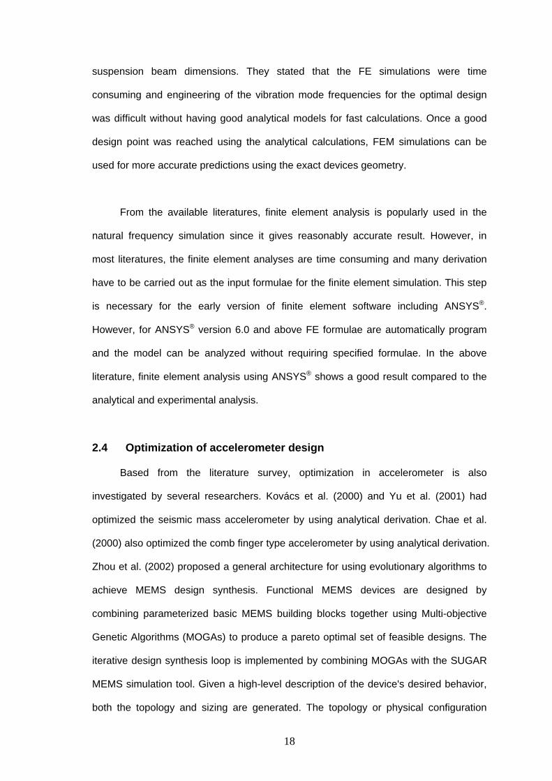
2.5 Summary
The literature review on the analysis of micro-accelerometer has been
discussed. Table 2.1 shows the summary of the literature review. From this table and
from the previous discussion on literature review, it can be observed that
accelerometer which is the start of MEMS is still continuing to grow, and now it is
applied to various applications. Comb finger type capacitive accelerometer is the most
successful type accelerometer since it gives high sensitivity in capacitance due to its
large sensing area. However, the researches on comb finger type accelerometer are
limited. By tracing back to the application of comb finger type device, this design has
been used in actuator for a long time. The research achievements in comb finger as
used in actuator can be used as the reference for comb finger type as being used in
accelerometer. Regardless of being used in accelerometer or actuators, resonant
frequency and stiffness constant in comb finger type are the interested parameters that
are being considered in the structural analysis. These parameters have been found out
analytically, numerically or experimentally.
These parameters depend mostly on the structural design of the suspension
beam. However, by referring to the literature review, structural analysis of suspension
beam has not been well investigated in comb finger type accelerometer. Thus, the
present work attempts to fill the lack in the above study and the goal is to develop a
methodology consisting of analytical and numerical investigation for structural analysis
and optimization of the structural design for the suspension beam in comb finger type
accelerometer.
19
Table 2.1 Summary of the literature reviewresearcher device sensing type suspention beam type device shape research type input parameter output parameter principle tool contribution
Borovic et al., 2005
optical switch (actuator)
electrostatic--capacitive
folded beam comb finger experimental, & simulation
voltage effective mass, stiffness constant, displacement
MATLAB/ SIMULINK
compare: open loop vs closed loop control
Chae et al., 2000 accelerometer capacitive folded beam comb finger analytical,
otimazation, FE,
fabrication,
testing
spring constant of beams, no of comb finger, length of comb finger (other devices geometry & material properties as dependent parameters)
high sensitivity, low noise, k, fn,
cross axis sensitivity (FE simulation),
shock resistance (FE simulation),
stress(FE simulation)
MATLAB, ANSYS micro-g performance, high-
precision accelerometer, high
sensitivity with low noiseChae et al., 2002 accelerometer capacitive folded beam comb finger length of finger, no of finger, k,
initial gap, thicknessresolution: sensitivity/TNEA, simulation result as above
MATLAB, ANSYS fabrication process, system
Kovács et al.
(2000)
accelerometer piezoresistive/
capacitive
cantilever and bridge type seismic mass Analytical,
optimazation
geometrical parameters: length,
width, thickness
strain, stress, max deflection,
bending moment, shear force,
bandwidth & device sensitivity,
physical sensitivity, eigen frequancy,
Rayleigh's energy
principle
MATHEMATICA
(analytical)
appropriate length ratio for
minimum necessary bandwidth.
Simplified model, diff beam typeLegtenberg et al.,
1996
actuators electrostatic--
capacitive
clamped-clamped, crab-leg
flexure,folded flexure
comb finger design, fabrication and experimental
several suspension design deflection behavior, axial spring
constant, k ratio, resonant frequency
Hooke's law, the total
potential energy
k ratio
Liu et al. 2002 resonators
(actuator)
electrostatic--
capacitive
folded beam comb finger analysis and
design
proof mass area and perimeter,
and the beam width
k, natural frequency, effective mass,
effective E, displacement
frequency characteristics. consider fabrication error in analytical derivetion
Lüdtke, et al.
2000
accelerometer capacitive folded beam comb finger FE simulated, designed and fabricated
structure height oscillation & frequency. K,
displacement sensitivity (cap/d)
ANSYS new fab method for high aspect
accLuo et al., 2002 accelerometer capacitive multi-layer suspending
springs, Corner attachment Serpentine spring. two turns each serpentine spring
comb finger analytical,
experimental
k, fn (exp), displacement sensitivity(exp), capacitive sensitivity(exp), noise, shock performance and cross axis sensitivity
Laplace
transformation
multi mat, Eeff
Tay et al., 2000 resonators
(actuator)
eletrostatic folded beam comb finger analytical, FE,
experimental
E, size parameters, structure
mass
resonant frequencies, electrostatic
spring effect
Rayleigh's energy
principle
simulation model: IntelliCAD, FEA model: ANSYS
electrostatic spring effect. Note: unable to verify experimentally with analytical
Urey et al., 2005 torsional scan
mirror (sensor)
microbridge central mass with comb finger
analytical, FEA,
experimental
various mirror shapes and flexure
dimensions
stifness constant, effective inertia & natural frequency of the first five vibration modes.
Euler-Bernoulli beam theory, Rayleigh's method
ANSYS Block-
Lanczos solver
correction factor
Wang et
al.(2004)
accelerometer PZT cantilever, bridge type, four
symmetric beam
seismic mass analytical model,
FEA
devices geometry (thinkness) &
elestic properties (diff material)
strain, stress, bending moment, charge, displacement, sensitivity, bandwidth, resonance frequency, (FE: max acc, 1st-5th mode)
Rayleigh's energy
principle
ANSYS 5.7 (FEA)
Block-Lanczos
solver
diff beam type, compare
analytical & FE, PZT/Si thickness
ratio.Wittwer et al.
2004
general cantilever, folded beam FEA, analytical devices geometry & elestic
properties
displacement, compliance (c, inv of
k), error
Castigliano’s
displacement theorem
optimal fillet ratio. analysis: combined both beanding and shear effect
Yu et al, 2001 accelerometer Piezoelectric cantilever, two cantilever, two symmetry (bridge), four symmetric beam
seismic mass analytical, FEA,
optimization
Material characteristics,
geometry
dynamic response (fn), trade-off, sensitivity, bending moment, stress, K, noise
Hooke's law ANSYS 5.3 dynamic response and trade-off
between several designZhou et al. 2003 actuators electrostatic tilted folded beam comb finger analytical
prediction, FEM,
experimental
k ratio, beam dimension, finger
gap, finger initial overlop area
negative spring constant, deflection,
spring constant
Hooke's law, Rayleigh-
Ritz mehtod, the total
potential energy
ANSYS 5.5
(Newton-raphson
method)
tilted folded beam, the stability of the comb-drive actuator is improved and the stable travel range is enhanced
Zhou et al., 2002 resonator
(actuator)
Corner attachment Serpentine spring. two turns each serpentine spring
comb finger MOGAs, SUGAR evolutionary algorithms, Multi-objective Genetic Algorithm
combining MOGAs with the SUGAR MEMS simulation tool
methodologies for device
synthesis, MOGAs in MEMS
CHAPTER 3 ANALYTICAL AND NUMERICAL FORMULATIONS
3.0 Overview
In this chapter the governing equations and the finite element formulation of
stiffness constant for suspension beam in micro-accelerometer are derived and solved.
The finite element simulation by using ANSYS® is also presented. The main topics
discussed in this chapter are shown below:
• Working mechanism of comb finger type accelerometer
• Several design models of suspension beams
• Equivalent stiffness constant in spring mass model
• Analytical derivations
• Finite element formulations
• Finite element modeling with ANSYS
3.1 Working mechanism of comb finger type accelerometer
Comb finger type device is one of the most common designs in MEMS device,
and it is normally used as sensors and actuators. It consists of two finger structures,
namely fixed fingers and movable fingers. The fixed fingers are anchored to the
substrate. The movable fingers are attached to a proof mass suspended by
compliant/suspension beams anchored to the substrate. Those movable and fixed
fingers are sometimes called sensing electrodes because they sense the acceleration
and measure it by using electronic circuitry. A typical design of comb finger type
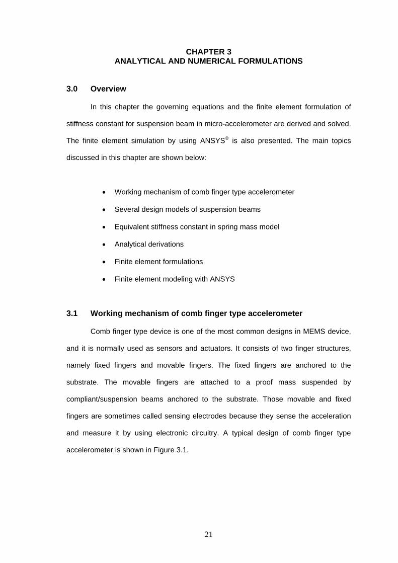
accelerometer is shown in Figure 3.1.
21
Figure 3.1: Typical design of comb finger type accelerometer (Lee et al, 2001)
In an actuator, when a voltage difference is applied between the comb
structures, an electrostatic force will be generated; resulted in a deflection of the
movable comb fingers, and move the movable parts to the desired position. However in
a sensor, when a comb finger type accelerometer is subjected to a measured external
force, in this case acceleration, the force is transferred to the proof mass through the
suspension beam. The proof mass together with movable fingers move along and
against the forced direction, while the fixed combs remain stationary, as shown in
Figure 3.2(a) and Figure 3.2(b). This movement changes the capacitance between the
fixed fingers and the movable fingers. This capacitance can be measured and
calibrated with the applied external force.
22

(a) In equilibrium condition (b) With an acceleration toward the left
Figure 3.2 Schematic arrangement of accelerometer (Doscher 2000)
The operations and response of the comb finger type accelerometer are
controlled by mass of the proof mass (M), stiffness constant (K) of suspension beam,
the damping (D) of air surrounding the structure, finger overlap area (A), finger initial
sensing gap (d0), and, of cause, the initial capacitance and acceleration. Among them,
the stiffness constant of the suspension beam takes significant role. The physical
meaning of dimension of a comb finger type accelerometer is shown in Figure 3.3.
Figure 3.3: The physical meaning of dimension of a comb finger type accelerometer
23
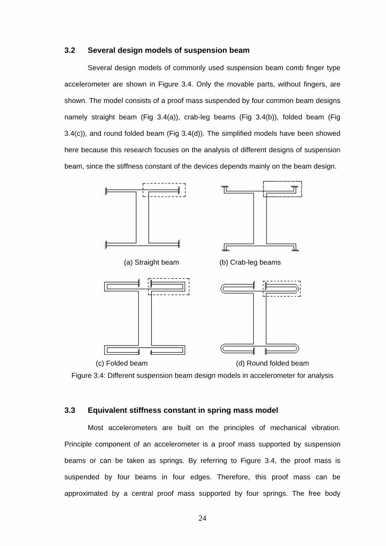
3.2 Several design models of suspension beam
Several design models of commonly used suspension beam comb finger type
accelerometer are shown in Figure 3.4. Only the movable parts, without fingers, are
shown. The model consists of a proof mass suspended by four common beam designs
namely straight beam (Fig 3.4(a)), crab-leg beams (Fig 3.4(b)), folded beam (Fig
3.4(c)), and round folded beam (Fig 3.4(d)). The simplified models have been showed
here because this research focuses on the analysis of different designs of suspension
beam, since the stiffness constant of the devices depends mainly on the beam design.
(a) Straight beam (b) Crab-leg beams
(c) Folded beam (d) Round folded beam
Figure 3.4: Different suspension beam design models in accelerometer for analysis
3.3 Equivalent stiffness constant in spring mass model
Most accelerometers are built on the principles of mechanical vibration.
Principle component of an accelerometer is a proof mass supported by suspension
beams or can be taken as springs. By referring to Figure 3.4, the proof mass is
suspended by four beams in four edges. Therefore, this proof mass can be
approximated by a central proof mass supported by four springs. The free body
24