analysis of vertical reinforcement in slender reinforced
TRANSCRIPT

ANALYSIS OF VERTICAL REINFORCEMENT IN SLENDER REINFORCED CONCRETE (TILT-UP) PANELS WITH OPENINGS & SUBJECT TO VARYING WIND PRESSURES
by
BRIAN D. BARTELS
B.S., Architectural Engineering, 2010
A REPORT
submitted in partial fulfillment of the requirements for the degree
MASTER OF SCIENCE
Department of Architectural Engineering and Construction Science College of Engineering
KANSAS STATE UNIVERSITY Manhattan, Kansas
2010
Approved by:
Major Professor Kimberly Waggle Kramer, P.E.

Abstract
This report offers a parametric study analyzing the vertical reinforcement for slender
reinforced concrete walls (tilt-up panels) subject to 90 miles per hour (mph), 110 mph, 130 mph,
and 150 mph three-second gust wind speeds. Wall panel heights of 32 feet (ft) and 40 ft are
considered for one-story warehouse structures. First, solid tilt-up panels serve as the base design
used in the comparison process. Next, square openings of 4 ft, 8 ft, 12 ft, and 16 ft centered in
the wall panel, are analyzed. A total of 32 tilt-up panel designs are conducted, establishing the
most economical design by the least amount of reinforcement and concrete used. In addition to
lateral wind pressures, the gravity loads acting on the load bearing tilt-up panel are dead load,
roof live load, and snow load. All loads for this report are determined based on a typical 24 ft by
24 ft bay. The procedure to design the tilt-up panels is the Alternative Design of Slender Walls
outlined in the American Concrete Institute standard ACI 318-08 Building Code Requirements
for Structural Concrete and Commentary Section 14.8
In general, an increase in panel height, lateral wind pressure, and/or panel openings,
requires an increase in reinforcement to meet strength and serviceability. Typical vertical
reinforcement in tilt-up panels is #4, #5, and #6 size reinforcement bars. A double-mat
reinforcement scheme is utilized when the section requires an increase in reinforcement provided
by use of a single-layer of reinforcement. A thicker tilt-up panel may be needed to ensure
tension-controlled behavior. Panel thicknesses of 7.25 inches (in), 9.25 in, and 11.25 in are
considered in design.
iii
Table of Contents
List of Figures ................................................................................................................................ vi
List of Tables ................................................................................................................................ vii
List of Terms ................................................................................................................................ viii
Acknowledgements ........................................................................................................................ xi
CHAPTER 1 - Introduction ............................................................................................................ 1
CHAPTER 2 - Scope of Research .................................................................................................. 2
CHAPTER 3 - Reinforced Concrete ............................................................................................... 5
3.1 Concrete ................................................................................................................................ 5
3.1.1 Portland Cement ............................................................................................................. 5
3.1.2 Admixtures ..................................................................................................................... 6
3.1.2.1 Air-Entraining Admixture ....................................................................................... 6
3.1.2.2 Water-Reducing Admixtures .................................................................................. 7
3.1.2.3 Accelerating Admixtures ........................................................................................ 7
3.1.2.4 Mineral Admixtures (pozzolans) ............................................................................ 7
3.1.2.5 Coloring Admixtures .............................................................................................. 8
3.1.3 Water .............................................................................................................................. 8
3.1.4 Aggregates ..................................................................................................................... 8
3.1.5 Compressive Strength .................................................................................................... 9
3.1.6 Tensile Strength ........................................................................................................... 10
3.1.7 Volume Change ........................................................................................................... 11
3.1.7.1 Shrinkage .............................................................................................................. 11
3.1.7.2 Creep ..................................................................................................................... 11
3.1.7.3 Thermal Expansion ............................................................................................... 12
3.1.8 Steel Reinforcement ..................................................................................................... 12
CHAPTER 4 - Slender Reinforced Concrete Wall (Tilt-up) Design ............................................ 13
4.1 Loads ................................................................................................................................... 13
4.1.1 Gravity Loads ............................................................................................................... 13
4.1.2 Dead Load ................................................................................................................ 14
4.1.3 Roof Live Load ........................................................................................................ 14

iv
4.1.4 Snow Load ............................................................................................................... 15
4.1.5 Lateral Loads ............................................................................................................... 15
4.1.5.1 Wind Pressure ....................................................................................................... 16
4.2 Alternative Design of Slender Walls – ACI 318-08, Section 14.8 ..................................... 19
4.2.1 Load Cases ................................................................................................................... 20
4.2.2 Design Moment Strength ............................................................................................. 21
4.2.2.1 Cracking Moment ................................................................................................. 24
4.2.2.2 Flexural Minimum Reinforcement ....................................................................... 25
4.2.3 Minimum Vertical Reinforcement ............................................................................... 25
4.2.4 Applied Ultimate Moment ........................................................................................... 26
4.2.4.1 Moment Magnifier Method................................................................................... 27
4.2.4.2 Iteration Method.................................................................................................... 29
4.2.5 Service Load Deflection .............................................................................................. 29
4.2.6 Minimum Horizontal Reinforcing ............................................................................... 31
CHAPTER 5 - Solid Panel Design Example ................................................................................ 32
5.1 Panel Design Properties ...................................................................................................... 32
5.2 Load Case 1 (C&C) ............................................................................................................ 35
5.2.1 Vertical Stresses ........................................................................................................... 36
5.2.2 Design Moment Strength ............................................................................................. 36
5.2.3 Applied Moment .......................................................................................................... 40
5.2.4 Service Load Deflection .............................................................................................. 42
5.3 Minimum Horizontal Reinforcement .................................................................................. 45
5.4 Summary ............................................................................................................................. 45
CHAPTER 6 - Panel with Opening Design Example ................................................................... 47
6.1 Panel Design Properties ...................................................................................................... 48
6.2 Load Case 1 (C&C) ............................................................................................................ 50
6.2.1 Vertical Stresses ........................................................................................................... 51
6.2.2 Design Moment Strength ............................................................................................. 52
6.2.3 Applied Moment .......................................................................................................... 54
6.2.4 Service Load Deflection .............................................................................................. 56
6.4 Minimum Horizontal Reinforcement .................................................................................. 58
v
6.5 Summary ............................................................................................................................. 59
CHAPTER 7 - Results and Conclusions ....................................................................................... 60
7.1 Solid Panel Results ............................................................................................................. 61
7.2 Panel with Opening Results ................................................................................................ 63
Works Cited .................................................................................................................................. 66
Appendix A - Sample Load Calculations ..................................................................................... 67
Appendix B - MWFRS and C&C Wind Pressures ....................................................................... 72
Appendix C - Load Combination Results .................................................................................... 75
Appendix D - Reprint Image/Figure Permission .......................................................................... 81

vi
List of Figures
Figure 2-1 Panel Configurations ..................................................................................................... 2
Figure 2-2 Case Study Floor Plan ................................................................................................... 3
Figure 3-1 Stress-Strain Curve (Nelson, 2006)............................................................................. 10
Figure 4-1 Net MWFRS Wind Pressures for a Windward Wall Case .......................................... 18
Figure 4-2 Applied Lateral Wind Pressure ................................................................................... 19
Figure 4-3 Determination of Strength Reduction Factor, φ (ACI Committee 318, 2008) ........... 21
Figure 4-4 Strain Distribution (ACI Committee 318, 2008)......................................................... 22
Figure 4-5 Equivalent Rectangular Stress Block (PCA, 2008) ..................................................... 23
Figure 4-6 Panel Analysis (ACI Committee 551, 2009)............................................................... 26
Figure 5-1 Solid Panel Geometry ................................................................................................. 33
Figure 5-2 Solid Panel Cross Section ........................................................................................... 34
Figure 5-3 Joist to Panel Connection ............................................................................................ 35
Figure 5-4 Moment Diagram ........................................................................................................ 41
Figure 5-5 Solid Panel Reinforcement Layout ............................................................................ 46
Figure 6-1 Design Model for Panel with Opening ........................................................................ 47
Figure 6-2 Panel with Opening Geometry .................................................................................... 49
Figure 6-3 Panel with Opening Cross Section .............................................................................. 50
Figure 6-4 Panel with Opening Reinforcement Layout ................................................................ 59
Figure 7-1 Relationship of Nominal Moment, Factored Moment, and Effective Area of
Reinforcement (ACI Committee 551, 2009) ........................................................................ 61
vii
List of Tables
Table 2-1 Seismic Out-of-Plane Force ........................................................................................... 4
Table 4-1 Dead Load .................................................................................................................... 14
Table 7-1 Solid Panel Results - 32 ft ............................................................................................ 62
Table 7-2 Solid Panel Results - 40 ft ............................................................................................ 62
Table 7-3 Panel with Opening Results - 32 ft ............................................................................... 63
Table 7-4 Panel with Opening Results - 40 ft ............................................................................... 64
Table B-1 MWFRS Wind Pressures - 32ft ................................................................................... 72
Table B-2 MWFRS Wind Pressures - 40 ft .................................................................................. 73
Table B-3 C&C Wind Pressures ................................................................................................... 74
Table C-1 Solid Panels - 32 ft ....................................................................................................... 78
Table C-2 Solid Panels - 40 ft ....................................................................................................... 78
Table C-3 Panel with Openings - 32 ft ......................................................................................... 78
Table C-4 Panel with Openings - 32 ft ......................................................................................... 78
Table C-5 Panel with Openings - 40 ft ......................................................................................... 79
Table C-6 Panel with Openings - 40 ft ......................................................................................... 80

viii
List of Terms
a – depth of equivalent stress block
Ag – gross area of concrete section
As – area of tension reinforcement
Ase – effective area of tension reinforcement
As,min – minimum area of reinforcement
b– width of the concrete section
c – distance from the extreme fiber to the neutral axis
Ce – exposure factor
Cs – slope factor
Ct – thermal factor
d – distance from the extreme concrete compression fiber to the centroid of tension of
reinforcement
dt – distance from the extreme compression fiber to centroid of extreme layer of
longitudinal tension steel
D – dead load
ecc – eccentricity of applied load(s)
Ec – concrete modulus of elasticity
Es – steel modulus of elasticity
f’c – compressive strength of concrete
fy – reinforcement yield stress
fr – modulus of rupture
G – gust effect factor
GCp – external pressure coefficient
GCpi – internal pressure coefficient
I – importance factor
Icr – cracked section moment of inertia
Ie – effective moment interia
Ig – gross concrete section moment of inertia
ℓc – unbraced height

ix
ℓw – width of concrete section
Kb – bending stiffness
Kz – velocity of pressure coefficient at height, z
Kzt – topographic factor
Kd – wind directionality factor
Lr – roof live load
Ma – maximum moment at mid-height of wall due to service lateral and eccentric vertical loads,
including P-Δ effects
Mcr – moment causing flexural cracking of the concrete section
Mmax – maximum moment occurring over the span of the panel due to uniform lateral loads
Mn – nominal moment strength at the mid-height cross-section
Mu – maximum combined moment at mid-height of wall due to factored lateral and eccentric
vertical loads including P-Δ effects
Mua – maximum moment at mid-height of wall due to factored lateral and eccentric vertical loads
not including P-Δ effects
n – modular ratio
P – applied axial load at top of panel
P-Δ – secondary moment caused by axial load P acting on a deflected shape with displacement Δ
Pua – factored axial load due to factored eccentric vertical loads
Pum – factored axial load due to factored eccentric vertical loads, including panel self-weight
above mid-height of panel
qh – effective velocity pressure at mean roof height, h
S – snow load
SDS – design spectral response acceleration parameter at short periods
SS – mapped short-period spectral acceleration
t – wall thickness
w – uniform lateral load
wu – factored uniform lateral load on element
W – wind load
yt – distance from centroidal axis of gross section to tension face
α – coefficient of thermal expansion

x
β1 – factor relating depth of equivalent rectangular compressive stress block to neutral axis depth
Δallow – maximum allowable deflection at mid-height
Δmax – maximum total deflection at mid-height
Δn – maximum potential deflection at mid-height
Δs – maximum out-of-plane deflection due to service loads, including P-Δ effects
Δu – computed deflection at mid-height of wall due to factored loads
εt – net tensile strain in extreme layer of tension steel at nominal strength
λ – modification factor reflecting the reduced mechanical properties of lightweight concrete
ρ – ratio of As to bd
ρl – ratio of area of distributed longitudinal reinforcement to gross concrete area perpendicular to
that reinforcement
Φ – strength-reduction factor

xi
Acknowledgements
I would like to thank the members of my committee, Professor Kimberly Kramer, P.E.,
Sutton Stephens, Ph.D., P.E., S.E., and Professor Raphael Yunk P.E., LEED A.P., for their
guidance in helping write this report. I would like to also thank Jeff Griffin, Ph.D., P.E., Vice
President of Operations for the CON/STEEL Division of LJB Inc. for continual support and
guidance in helping me understand the engineering of tilt-up concrete panels.

1
CHAPTER 1 - Introduction
This report includes a parametric study evaluating the vertical reinforcing requirements
for concrete tilt-up wall panels with various sized openings centered in the panel subject to
varying wind speeds applied perpendicular to the surface. For academia, the technical
description of reinforced concrete slender walls is appropriate, whereas tilt-up wall panels is
common within the construction industry. The report begins with an overview of concrete
material properties, reinforcing steel, and the basic mechanics of reinforced concrete; next, it
evaluates the vertical reinforcement resisting out-of-plane forces in accordance with the
American Concrete Institute standard ACI 318-08 Building Code and Commentary Section 14.8,
Alternative Design of Slender Walls. Two design calculation examples, one of a solid tilt-up
wall panel and one of a wall panel incorporating an opening, are presented to demonstrate the
analysis process used throughout the study. Finally, the end of this report provides the design of
the vertical reinforcement for all panel scenarios discussed in Chapter 2.
CHAPTER 2 - Scope of Research
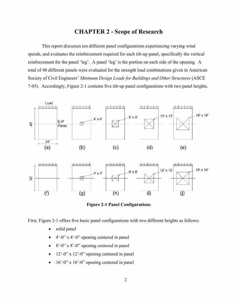
This report discusses ten different panel configurations experiencing varying wind
speeds, and evaluates the reinforcement required for each tilt-up panel, specifically the vertical
reinforcement for the panel ‘leg’. A panel ‘leg’ is the portion on each side of the opening. A
total of 40 different panels were evaluated for the strength load combinations given in American
Society of Civil Engineers’ Minimum Design Loads for Buildings and Other Structures (ASCE
7-05). Accordingly, Figure 2-1 contains five tilt-up panel configurations with two panel heights.
Figure 2-1 Panel Configurations
First, Figure 2-1 offers five basic panel configurations with two different heights as follows:
• solid panel
• 4’-0” x 4’-0” opening centered in panel
• 8’-0” x 8’-0” opening centered in panel
• 12’-0” x 12’-0” opening centered in panel
• 16’-0” x 16’-0” opening centered in panel
2
The openings are located in the center of the panels where the largest stresses occur, causing the
worst case scenario. In addition, Figure 2-1 accounts for panel configurations (a)-(e) that have
an unbraced length, ℓc, of 32 feet (ft) and panel configurations (f)-(j) that have an unbraced
length, ℓc, of 40 ft. According to Tilt-Up Concrete Association (TCA), the 32 ft and 40 ft
unbraced lengths are common for warehouse structures (Schmitt, 2009). Each of the ten load
bearing tilt-up panels are designed for 90 mph, 110 mph, 130 mph, and 150 mph wind speeds
using the Analytical Method in Chapter 6 of ASCE 7-05 provisions. The Main Wind Resisting
Forces (MWRF) and Components and Cladding (C&C) forces were determined and compared.
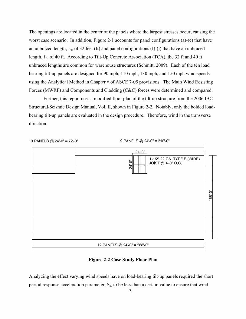
Further, this report uses a modified floor plan of the tilt-up structure from the 2006 IBC
Structural/Seismic Design Manual, Vol. II, shown in Figure 2-2. Notably, only the bolded load-
bearing tilt-up panels are evaluated in the design procedure. Therefore, wind in the transverse
direction.
Figure 2-2 Case Study Floor Plan
3
Analyzing the effect varying wind speeds have on load-bearing tilt-up panels required the short
period response acceleration parameter, Ss, to be less than a certain value to ensure that wind

pressures due to MWRF and C&C govern over seismic forces. The out-of-plane force due to
seismic load for structural walls is defined by Section 12.11.1 of ASCE 7-05. Where the soil
properties are not known in sufficient detail, Site Class D is assumed as defined in Section 11.4.2
of ASCE 7-05 provisions. Specifically, the scope of this report covers the tilt-up structure
located in regions that meet the short period response acceleration values shown in Table 2-1.
Table 2-1 Seismic Out-of-Plane Force
Naturally, soil conditions change vastly throughout the desired spectrum of wind speed regions;
therefore, for simplicity, the study assumes a shallow foundation (continuous footings) for all
panel scenarios. This report does not include design of the foundation, panel/foundation, and
foundation/soil interfaces.
4
5
CHAPTER 3 - Reinforced Concrete
As with any building material, an understanding of the material properties and mechanics
is important when determining the most appropriate design. Such an understanding clearly is
important for reinforced concrete, which is used globally. The design of slender reinforced
concrete wall panels is directly associated with the basic mechanics and properties of concrete
and reinforcing steel. Thus, this chapter offers a broad overview of the materials of concrete and
reinforcing steel. Hardened concrete is a brittle material with a tensile strength of approximately
one-tenth of its compressive strength. Therefore, in structural concrete, reinforcing steel adds
tensile load-carrying capacity and overall toughness. Although recent research and development
have revealed other materials beside steel such as fiber reinforced plastic (FRP) to reinforce
concrete successfully, the most common practice for tilt-up construction is the use of steel
reinforcing. Therefore, this report focuses on billeted reinforcing steel.
3.1 Concrete Concrete is a mixture of water, aggregates, and cementitious materials mainly cement.
Water and portland cement, through the chemical reaction hydration, form a paste that binds the
aggregates into a rock-like mass. Hydration can take place under water as well as when exposed
to air. Meanwhile, aggregates consist of coarse and fine aggregates and are graded in size from
sand to gravel (MacGregor, 2005).
3.1.1 Portland Cement
Most concretes are made with portland cement, a hydraulic cement manufactured mostly
from lime and silica with small quantities of gypsum and iron oxide. The process begins with
the crushing of the raw materials that begin as massive rocks. After a gradual crushing of the
raw materials, appropriate testing determines physical and chemical make-up. Specifically, the
material is combined chemically under extremely high temperatures of 3400 degrees Fahrenheit
in a kiln, resulting in a substance called ‘clinker’. The clinker is then cooled and ground into the
gray powder known as portland cement. In the United States, five basic types of portland cement
are defined by the American Society for Testing and Materials, ASTM C 150 (Kosmatha,
Kerkhoff, & Panarese, 2002):
6
• Type I, regular portland cement – general all-purpose cement used in reinforced concrete buildings, bridges, and anywhere that special properties of concrete are not desired
• Type II, moderate sulfate resistance – modified cement that can withstand moderate sulfate exposure and generates heat of hydration more slowly than Type I
• Type III, high early strength – a cement that develops in a week or less the strength that Type I develops at 28 days and therefore has a much higher heat of hydration to reach early strength
• Type IV, low heat of hydration – low heat cement develops strength at a slower rate than Type I and typically is used for large concrete structures such as dams
• Type V, high sulfate resistance – modified cement that can withstand exposure to high concentrations of sulfate and typically is used for footings and basement walls
Where certain concrete properties are desired, various admixtures can be added to the cement
(How Portland Cement is Made, 1963).
3.1.2 Admixtures
Admixtures are added to concrete during or before mixing to attain certain qualities. The
main reasons for using admixtures include the following: to reduce the cost of concrete
construction, to achieve certain properties in concrete, and to maintain the quality of concrete
during construction (Kosmatha, Kerkhoff, & Panarese, 2002). Admixtures typically used for tilt-
up concrete buildings follow (Tilt-Up Concrete Association, 2004):
• air-entraining admixtures
• water-reducing admixtures
• accelerating admixtures
• mineral admixtures
• coloring admixtures
3.1.2.1 Air-Entraining Admixture
Air-entraining admixtures, as defined by ASTM C260, improve concrete’s resistance to
freezing and thawing. Such additives contain minute air bubbles that are distributed uniformly
throughout and that provide relief spaces for the water to go to as the water freezes in the
concrete. As the concrete temperature increases and the ice melts, the water moves out of the air

7
voids, resulting in less cracking in the concrete (Tilt-Up Concrete Association, 2004) (Nelson,
2006).
3.1.2.2 Water-Reducing Admixtures
Water-reducing admixtures, as specified in ASTM C494, reduce the quantity of mixing
water required to produce concrete of a certain slump, which reduces the water-to-cement ratio.
As the water-to-cement ratio is reduced, the concrete compressive strength increases.
Consequently, the 28-day compressive strength of a water-reduced concrete can be anywhere
from 10 to 25 percent greater than for concrete without the water-reducing admixture. Typical
water reducers reduce the water content by approximately 5 to 10 percent (Kosmatha, Kerkhoff,
& Panarese, 2002).
3.1.2.3 Accelerating Admixtures
An accelerating admixture, as specified in ASTM C494, accelerates the rate of hydration
and therefore the strength gain of the concrete. Accelerating admixtures allow for earlier
finishing of the concrete in cold weather and the 28-day compressive strength can be reached at
approximately seven days when using appropriate concreting methods. Notably, non-chloride
accelerators are preferred in tilt-up panels so as not to corrode the reinforcing steel (Tilt-Up
Concrete Association, 2004).
3.1.2.4 Mineral Admixtures (pozzolans)
Mineral admixtures, such as fly ash and silica fume, have recently become popular for
economical reasons. In general, mineral admixtures replace anywhere from 10 to 50 percent of
the portland cement. Fly ash is the most commonly used pozzolan and is specified by ASTM
C618. Fly ash is the by-product of coal-burning power plants while silica fume is a by-product
of induction arc furnaces in the production of silicon. Using pozzolans for partial replacement of
the portland cement can improve the workability of the concrete by producing a more
cementitious paste, but tends to cause a slower strength gain since the pozzolanic reaction
generates less heat. Therefore, it may not always be desirable for tilt-up construction (Kosmatha,
Kerkhoff, & Panarese, 2002).

8
3.1.2.5 Coloring Admixtures
Natural and synthetic materials color concrete for aesthetic reasons, and ASTM C979 is
the specification for pigments for integrally colored concrete. Pigments can be in the form of
powder or liquid (Good, 2006).
3.1.3 Water
ACI 318-08 Building Code Requirements for Structural Concrete and Commentary
Section 3.4.1 specifies any potable water is considered suitable for making concrete. This is
because any contaminants in the water can result in altered setting time of the mix or reduced
concrete strength as well as corrosion of the steel reinforcement. Moreover, a relatively small
amount of water is required to hydrate portland cement. An important characteristic of structural
concrete is the water-to- cementitious material (w/cm) ratio, which is defined as the number of
pounds of water used per pound of cement. The w/cm parameter can help determine the strength
of concrete. Two opposing, yet desirable properties are affected by the w/cm: strength and
workability. Concrete mixes that have low w/cm are stronger and more durable than those with
high w/cm. Concrete must be both strong and workable, therefore requiring a careful balance of
the w/cm. Most reinforced concretes have w/cm between about 0.4 and 0.7. A w/cm of 0.4
corresponds to a 28-day compressive strength of about 4,700 pounds per square inch. The w/cm
affects the amount of shrinkage because high water content will decrease the volume taken by
the aggregates. Excess water in the concrete also increases bleeding, which is the appearance of
water on the fresh concrete surface. As the aggregates and cement particles settle, water used for
mixing is forced to the surface (Concrete Bleeding, 1988). Excessive bleeding can lead to
reduced strength near the surface, delayed finishing operations, and undesirable results if the
concrete surface is finished before bleed water has evaporated (MacGregor, 2005).
3.1.4 Aggregates
Aggregates are generally divided into two groups: fine and coarse. Fine aggregates
consist of natural sand or manufactured sand produced by crushing rock to particle sizes ranging
up to ⅜ inch. If most of the particles are larger than ¼ inch, the aggregate is considered coarse
aggregate, which may be gravel or crushed material, such as stone. Most concrete used in
superstructures of building construction has a maximum aggregate size from ¾ inch to 1-1/2

9
inch. The largest desirable aggregate depends on the size and shape of the member to be made
of concrete and on the spacing and location of reinforcing steel. Maximum size aggregates that
can be used in reinforced concrete are specified in Section 3.3.2 of ACI 318-08. Nominal
maximum size of coarse aggregate should not be larger than:
(a) 1/5 the narrowest dimension between sides of forms, nor
(b) 1/3 the depth of slabs, nor
(c) 3/4 the minimum clear spacing between individual reinforcing bars or wires
The maximum size aggregate commonly used in tilt-up panels is ¾ inch to 1 inch (Tilt-Up
Concrete Association, 2004). The aggregate size contributes to the designation of normal weight
concrete or light weight concrete. Normal weight concrete is the most commonly used in tilt-up
panels, whereas weights equal to or less than 115 lb/ft3 are considered light weight concretes.
Although light weight concrete can be advantageous in that it provides a lighter wall panel, the
reduced mechanical properties of the concrete and greater material cost are both undesirable.
The aggregates used for these concretes are made from expanded shales of volcanic origin, fired
clays, or slag (Nelson, 2006). Finally, aggregates make up 60 to 75 percent of the solid volume
of concrete (Kosmatha, Kerkhoff, & Panarese, 2002).
3.1.5 Compressive Strength
The strength of a concrete and its stress-strain curve form the basis of all structural
computations since strength of concrete is determined at 28 days by its compressive stress at
failure, as defined in ASTM C39. To determine this compressive stress, a sample of the concrete
is traditionally formed into a 12 inch long by 6 inch diameter cylinder. The cylinder is left to
cure for 28 days and then placed in a compression test machine and loaded at a continuous rate
until a well-defined fracture pattern occurs. The compressive stress at ultimate load is known as
the 28-day strength and for design purposes labeled as f’c in pounds per square inch (psi).
Concrete will achieve about 60-75% of its design strength at 7 days; however it continues to gain
strength for months or even years after placement (MacGregor, 2005).
Concrete is not a truly elastic material; however, it is reasonably elastic within the lower
portion of its ultimate strength as shown on the stress-strain curve in Figure 3-1.

Figure 3-1 Stress-Strain Curve (Nelson, 2006)
For design, a range of about 40 to 45 percent of the compressive strength (f’c) of concrete is
treated as elastic (Nelson, 2006), and an approximation of the slope of the initial portion of the
curve is defined as the modulus of elasticity. The value of the modulus of elasticity increases as
the strength of the concrete increases as the following equation for normal weight concrete
shows:
57,000 'c cE f= Equation 3-1
where f’c is the ultimate strength of the concrete in pounds per square inch (psi).
3.1.6 Tensile Strength
The tensile strength of concrete varies from about 8 to 15 percent of its compressive
strength (Nelson, 2006). Although the tensile strength of concrete is usually neglected in
design, the ultimate tensile strength is important when a reinforced concrete member is subject to
flexural loading. ASTM C78 defines the flexural test in which a plain concrete beam spanning
10

24 inches and measuring 6 inches by 6 inches by 30 inches long is loaded in flexure at the third
points. Once failure occurs due to cracking on the tensile face of the test beam, the modulus of
rupture (fr) measured in psi is calculated from the following formula where M is the maximum
applied moment, b is the width of the beam, and h is the depth of the beam:
2
6r
Mfbh
=
Equation 3-2
ACI 318-08 Section 9.5.2.3 provides the following formula for the modulus of rupture:
7.5 'r cf fλ= Equation 3-3
where λ = 1.0 for normal weight concrete as defined in Section 8.6.1 of ACI 318.
3.1.7 Volume Change
Design should consider three areas, as concrete will experience volume change due to
shrinkage, creep, and thermal expansion.
3.1.7.1 Shrinkage
Any excess water that is free to evaporate as the concrete hardens can reduce the size of
the member and is called shrinkage. Shrinkage only occurs to the concrete and not the
reinforcement and it can produce internal stresses and tension cracking for areas with restrained
ends. Consequently, horizontal reinforcing is provided for tilt-up panels to help resist cracking.
3.1.7.2 Creep
When concrete is subjected to loading it experiences deformation. After initial
deformation occurs, the additional deformation is called creep or plastic flow. Creep will vary
with both time and intensity of load. A tilt-up panel that experiences creep could lead to an
increase in deflections and P-Δ effects. Although not included in the panel designs within this
report, a minimum initial deflection of lc/400 is recommended to account for creep and panel
bowing (ACI Committee 551, 2009) (Nelson, 2006).
11

12
3.1.7.3 Thermal Expansion
The coefficient of thermal expansion (α) for normal weight concrete ranges from 5 to 7 x
10-6 per unit length per degree Fahrenheit. For steel, the coefficient is 6.5 x 10⁻⁶ per unit length
per degree Fahrenheit. As concrete experiences changes due to temperature effects, steel will
experience similar changes since both coefficients of thermal expansion are relatively close
(MacGregor, 2005).
3.1.8 Steel Reinforcement
Concrete is strong in compression but weak in tension. Therefore, reinforcement such as
steel is placed in the structural member at locations that experience tensile forces.
Reinforcement used in tilt-up panels is typically ASTM A615, Grade 60 with minimum yield
strength of 60,000 psi. Although reinforcing bars can be plain or deformed, deformed are most
commonly used for reinforcement in tilt-up construction as it provides a better bond with the
concrete. Reinforcement for tilt-up panels are typically #4, #5, or #6 bars (Tilt-Up Concrete
Association, 2004). In some cases, the engineer will allow welded wire reinforcement to replace
reinforcement bars. Finally, the modulus of elasticity (Es) for all steel reinforcing is 29 x 106 psi.

13
CHAPTER 4 - Slender Reinforced Concrete Wall (Tilt-up) Design
Walls are designed to resist concentric or eccentric vertical axial loads, out-of-plane loads
applied perpendicular to the face of the wall, and in-plane horizontal loads. Bending in walls
results from lateral loads and eccentrically applied vertical axial loads. As the height of the wall
increases, the need arises to account for the reduced axial load carrying capacity of the wall due
to slenderness effects. The main effect of slenderness is the development of additional bending
due to deflection (P-Δ effect). The common analytical model used for design is a load-bearing
wall panel that spans vertically from the foundation or slab-on-grade to intermediate floor(s)
and/or the roof (ACI Committee 551, 2009). Therefore, the tilt-up wall panels in this report
span vertically from the slab-on-grade to the roof level. Due to various foundation depths that
may occur due to freeze/thaw requirements, it is assumed that the tilt-up wall panels are braced
at the floor slab which is a common construction practice (Robert Drysdale, 2008). Therefore,
the additional panel length required for various foundation conditions is not considered.
4.1 Loads The first step in designing any structural member is to determine the loads acting on the
member. A load-bearing tilt-up panel experiences loading in three directions: vertically (axial),
out-of-plane (lateral), and in-plane horizontally (shear). In particular, the load bearing tilt-up
panels for this report are designed for gravity loads and lateral wind pressure. This lateral wind
pressure can be the Main Wind-Force Resisting System (MWFRS) wind pressure which acts
perpendicular to the wall surface and simultaneously perpendicular to the roof surface; or the
C&C wind pressure which acts only perpendicular to the wall surface. Furthermore, all loads are
based on a typical 24’-0” x 24’-0” bay as shown in Figure 2-2. Sample calculations are provided
in Appendix A, while ASCE 7-05 and its commentary provide the necessary information to
determine the loads acting on the panel.
4.1.1 Gravity Loads
The gravity loads acting on the load-bearing tilt-up panel are dead load, roof live load,
and snow load. For this study, steel joists spaced 4’-0” on center result in six axial point loads

along the top edge of the panel, resulting in a uniformly distributed load along the panel width at
the mid-height of the panel. The panels highlighted along the longitudinal direction in
Figure 2-2 will experience higher axial loads and therefore greater P-Δ effects because the joists
frame into the panel. Meanwhile, the panels along the transverse direction would be designed
for a much smaller, uniformly distributed load based on the tributary area concept and a single
concentrated load resulting from the beam supporting the joists framing into the panel. This
design is outside the scope of this report.
4.1.2 Dead Load
Dead load (D) is the weight of all the materials in the structure: self weight, weight of
any fixed equipment, and weight of architectural features. The magnitudes of dead loads for
various construction materials are in Table C3-1 of ASCE 7-05 provisions. Table 4-1 depicts the
estimated dead load used for panel design in this report.
Table 4-1 Dead Load
The magnitudes provided in the standard are only an estimate; therefore any deviation is at the
discretion of the engineer.
4.1.3 Roof Live Load
Roof live load (Lr) is for construction materials and workers and is based on the slope of
the roof and the designated tributary area. Although ASCE 7-05 does allow for reduction in roof
live loads with the minimum design load being 12 psf, no reduction was considered in this study.
Instead, the roof is considered a flat, ordinary roof, and therefore the roof live load is 20 psf as
defined in Table 4-1 of ASCE 7-05.
14

15
4.1.4 Snow Load
ASCE 7-05 contains maximum measured ground snow loads and ground snow loads with
a 2% annual probability of being exceeded (50-year mean recurrence interval). The ground
snow load (pg), given in Table 7-1 of ASCE 7-05, determines design ground snow load. Also,
ASCE 7-05 defines the flat roof snow load (pf), on a roof with a slope equal to or less than 5o
from the following equation:
pf = 0.7CeCtIpg Equation 4-1
The following coefficient values were given in order to establish a reasonable load for designs
conducted throughout the study. Exposure factor (Ce) accounts for the slow down effects of site
terrain. A factor of 1.0 is based on exposure category C and assumes a partially exposed roof.
Thermal factor (Ct) accounts for the thermal condition of the roof and how much heat will pass
through the roof and melt snow off the roof. A factor of 1.0 is used based on not meeting the
conditions outlined in Table 7-3 of ASCE 7-05. A building category II with an importance
factor (I) of 1.0 is used to relate the design load to the consequences of failure.
Given that snowdrifts can occur on roofs in the shadow of higher roofs, or in this case,
the parapet, ASCE 7-05 defines snowdrift loads as a surcharge load that is imposed on the
balanced snow load, pf. Snow drift applies only if the ratio hc/hb ≥ 0.2. Appendix A of this
report provides load calculations for a roof snow load (pf) based on a ground snow load (pg) of
20 psf. This study considers a maximum flat roof snow load without drifting, including rain-on-
snow to be 20 psf; equal to the roof live load value.
4.1.5 Lateral Loads
Lateral loads act horizontally for Main Lateral Force Resisting System (MLFRS) and
C&C and are known as out-of-plane loads. In-plane loads can also occur for the MLFRS. Wind
pressures or equivalent static seismic pressure based on seismic response accelerations are
generally applied to the tilt-up walls as uniformly distributed lateral loads. For this report, lateral
loading pressures due to wind govern. ASCE 7-05 provisions specify three procedures for
determining design wind loads: Simplified Procedure (Method 1), Analytical Procedure (Method

16
2), and Wind Tunnel Procedure (Method 3). Each procedure has limitations and/or
complications regarding suitability for design; however, for this report, the Analytical Procedure
(Method 2) will be used for determining the design wind pressures for MLFRS and C&C.
4.1.5.1 Wind Pressure
The Analytical Procedure outlined in Section 6.5 of ASCE 7-05 provides wind pressures
for the design of C&C and for the MWFRS. To determine design wind loads in accordance with
the Analytical Procedure requires the following conditions of ASCE 7-05 Section 6.5.1:
• the building or other structure must be regular-shaped, having no unusual
geometrical irregularity
• the building or other structure must not experience across wind loading, vortex
shedding, instability due to galloping or flutter; or be on a site location
susceptible to special wind channeling effects
For the MWFRS, this procedure involves determining wind velocity at any height (qz), wind
directionality (Kd), gust effect factor (G), and pressure coefficients (GCpf and GCpi). The
procedure also accounts for topographic features (Kzt), different wind exposures, and geometric
configuration.
The pressure coefficients reflect the loading on each building surface due to wind
direction, the transverse direction in this case. For either the MWFRS or C&C, the velocity
pressure (qh) at mean roof height, h is defined by the following equation:
qh =0.00256KzKztKdV2I (lb/ft2) Equation 4-2
The basic wind speeds (V) in this report are 90 miles per hour (mph), 110 mph, 130 mph, and
150 mph, and they correspond to 3-second gust speeds at 33 feet (10 m) above ground for
exposure category C, which ASCE 7-05 defines as open terrain with scattered obstructions of
heights generally less than 30 feet. Exposure category C is appropriate for the higher wind
speeds, which correspond to hurricane prone regions. The topographic factor (Kzt) is a multiplier
used to account for higher wind speeds that can be generated due to an isolated hill or
escarpment; in this case, the factor of 1.0 is used assuming generally flat ground. Next, ASCE 7-
05 contains a single gust effect factor of 0.85 for rigid buildings. A building is considered rigid

17
when the building structure’s frequency, in Hertz (Hz), is greater than 1.0. The structure used for
this report is said to be rigid as determined in Appendix A. A building structure can be classified
as open, partially enclosed, or enclosed, all of which are defined in Section 6.2 of ASCE 7-05.
This classification of a structure determines the appropriate internal pressure coefficient in
Figure 6-5 of ASCE 7-05. This study assumes an enclosure classification of partially enclosed,
resulting in higher internal wind pressures than for the enclosed classification and is common for
warehouses with large openings on one side.
The lateral pressure applied to the panel for design is the wind pressure determined for
C&C. However, the lateral pressures from the MWFRS should be compared to lateral pressures
determined by the C&C method. Appendix B provides the MWFRS lateral pressures that would
be used for design. More times than not, the lateral pressure determined by C&C will be larger
due to the smaller effective area receiving the wind pressure therefore, a higher average wind
pressure occurs. ASCE 7-05 Section 6.5.12.4.1 provides the design wind pressures on C&C
elements of low-rise buildings.
p = qh[(GCp) - (GCpi)] (lb/ft2) Equation 4-3
Design wind pressures can be negative or positive, and the designation is determined by the net
pressure resulting between the internal and external pressures. For clarity, Figure 4-1 shows the
net pressure determination for a windward wall case using partially enclosed classification for
MWFRS.

Figure 4-1 Net MWFRS Wind Pressures for a Windward Wall Case
For the partially enclosed classification, both positive and negative internal pressures must be
considered, and the net pressures of -2.62 psf and 16.58 psf can be verified in Appendix B under
Zone 1 (windward). Notably, a windward case is provided for clarity, whereas the leeward case
usually produces the more critical wind pressure. A negative net pressure, or suction, acts away
from the element while a positive net pressure, or pressure, acts towards the element. As Figure
4-2 shows, suction is the more critical situation since it will increase the moment at mid-height
of the panel with the eccentric (ecc) axial load.
18

Figure 4-2 Applied Lateral Wind Pressure
Figure 6-10 of ASCE 7-05 provides the appropriate pressure coefficients for the MWFRS. For a
roof angle (θ) 0 to 5o, Appendix A shows the external pressure coefficients (GCpf). ASCE 7-05
Section 6.5.12.2.2 provides the design wind pressure for the MWFRS of low-rise buildings
where the mean roof height (h) does not exceed 60 feet and does not exceed the least horizontal
dimension.
p = qh[(GCpf) - (GCpi)] (lb/ft2) Equation 4-4
The MWFRS lateral pressures are applied perpendicular to the walls and roof. These forces are
transferred to the diaphragm and then into the tilt-up panels parallel to the applied wind direction
as in-plane forces; however, this analysis is outside the scope of this report. The MWFRS wind
pressures are less than the C&C wind pressures and therefore, do not govern the design.
4.2 Alternative Design of Slender Walls – ACI 318-08, Section 14.8 The design concepts and code limitations for slender walls were tested and confirmed by
the American Concrete Institute – Structural Engineers Association of Southern California (ACI-
SEAOSC) Task Committee on Slender Walls, 1980 to 1982. The report of the task committee
includes design requirements and procedures, analysis methods, and load/deflection relations
(Athey, 1982). The alternative design of slender walls was introduced in 1999 in the ACI 318
19

20
code, which was based on the provisions of the 1997 Uniform Building Code (UBC). According
to Section 14.8.2 of ACI 318-08, walls designed by the alternative design method must satisfy
the following limitations:
• the wall panel shall be simply supported, axially loaded subjected to an out-of-
plane uniform lateral load, with maximum moments and deflections occurring at
midspan
• constant cross-section over the height of the panel
• cross-section of wall must be tension-controlled
• reinforcement must provide a design moment strength (ΦMn) greater than or
equal to the cracking moment (Mcr)
• concentrated gravity loads applied to the wall above the design flexural section
must be distributed over a width equal to the lesser of the bearing width plus a
width on each side that increases at a slope of 2 vertical to 1 horizontal down to
the design flexural section or the spacing of the concentrated loads but not
extending beyond the edges of the wall panel
• vertical stress Pu/Ag at the mid-height section shall not exceed 0.06f’c
When one or more of the above limitations is not met, the wall design must meet the provisions
outlined in Section 14.4 of ACI 318-08 in which walls subject to axial load or combined flexure
and axial load be designed as compression members, requiring tied vertical reinforcement.
4.2.1 Load Cases
The Strength Design Method requires that structural elements at any section have design
strengths at least equal to the required strengths calculated by the code-specified factored load
combinations as defined in Section 9.2 of ACI 318-08. The following load combinations
determine the required strength, U:
U = 1.4D (ACI Equation 9-1)
U = 1.2D + 0.5(Lr or S) (ACI Equation 9-2)
Load Case 1 U = 1.2D + 1.6(Lr or S) + 0.8W (ACI Equation 9-3)
Load Case 2 U = 1.2D + 1.6W + 0.5(Lr or S) (ACI Equation 9-4)
U = 1.2D + 1.0E + 0.2S (ACI Equation 9-5)
Load Case 3 U = 0.9D + 1.6W (ACI Equation 9-6)
U = 0.9D + 1.0E (ACI Equation 9-7)
For this parametric study, Load Case 1 determines the greatest applied force due to gravity loads.
Load Case 2 and Load Case 3 determine the largest out-of-plane loading applied to wall panel.
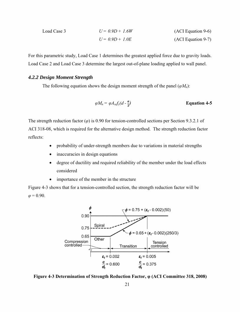
4.2.2 Design Moment Strength
The following equation shows the design moment strength of the panel (φMn):
φMn = φAsefy(d - ) Equation 4-5
The strength reduction factor (φ) is 0.90 for tension-controlled sections per Section 9.3.2.1 of
ACI 318-08, which is required for the alternative design method. The strength reduction factor
reflects:
• probability of under-strength members due to variations in material strengths
• inaccuracies in design equations
• degree of ductility and required reliability of the member under the load effects
considered
• importance of the member in the structure
Figure 4-3 shows that for a tension-controlled section, the strength reduction factor will be
φ = 0.90.
Figure 4-3 Determination of Strength Reduction Factor, φ (ACI Committee 318, 2008)
21

Two criteria can verify that the section is indeed tension-controlled:
t
cd≤ 0.375 or tε ≥ 0.005
Figure 4-4 shows, given strain compatibility principles, the nominal flexural strength of a
member is reached when the strain in the extreme fiber in compression reaches the assumed
strain limit of 0.003 for concrete.
Figure 4-4 Strain Distribution (ACI Committee 318, 2008)
The effective area of reinforcement is defined by the following equation:
2um
se sy
P hA Af d
= +
Equation 4-6
The first term is the area of reinforcement (As) due to reinforcement placed in the cross-section.
The second term contains a compressive force due to the factored applied axial loads (Pum) which
includes the contributing panel self-weight. The panel self-weight above mid-height is critical
because it adds additional axial load at the critical midspan section for a simply supported
member. Notably, a single layer of reinforcement and a double layer of reinforcement
differently affect the small gain of bending resistance due to the applied axial loads. Before ACI
318-08, the effective area of reinforcement overestimated the contribution of axial load when
using two layers of reinforcement; therefore, the ratio h/2d has since been added (PCA, 2008).
22

This ratio will be very close to 1.0 for a single layer of reinforcement where h is the panel
thickness, and d is the distance from the top of the cross-section to the centroid of the tension
reinforcement steel. For a double layer of reinforcement, the additional bending resistance
reduces.
ACI 318-08 allows an equivalent rectangular compressive stress block to replace the
more exact parabolic stress distribution. Figure 4-5 shows such a stress block for a simply-
supported member loaded from the top with a downward force.
Figure 4-5 Equivalent Rectangular Stress Block (PCA, 2008)
To easily calculate the nominal moment strength, requires a few simple assumptions. At
ultimate strength, an average concrete stress of intensity 0.85f’c is uniformly distributed across
the equivalent compression zone bounded by the edges of the cross-section and a straight line
located parallel to the neutral axis at depth a = β1c from the fiber of the maximum compressive
strain (Mattock, Kriz, & Hognestad, 1961). Determined experimentally, the factor β1 is a ratio of
average stress to maximum stress and is taken as 0.85 for concrete compressive strength of 4,000
psi. Moreover, ACI 318-08 Section 10.2.7.2 defines c as the distance from the fiber of
maximum strain in compression, to the neutral axis. However, tensile strength of the concrete is
23

typically neglected. Therefore, the total tensile force is taken by the reinforcement steel and
defined by the following:
T = Asefy Equation 4-7
The total compressive force (C) is the volume of the equivalent rectangular stress block
multiplied by the average concrete stress:
C = 0.85f’cab Equation 4-8
The compression force and the tension force must be equal to maintain equilibrium at the cross-
section and allow for the determination of the depth of the stress block:
0.85f’’cab = Asefy Equation 4-9
a = 0.85 '
se y
c
A ff b
Equation 4-10
Once this expression is found, the distance (or moment arm) between the centroid of the tension
and compression force equals (d – a/2). To satisfy strength design requirements, the nominal
moment strength multiplied by the strength reduction factor, must be greater than or equal to the
factored applied moment discussed in Section 4.2.4.
4.2.2.1 Cracking Moment
To prevent sudden failure at the point cracking first occurs, ACI 318-08 Section 14.8.2.4
requires the cross-section of the slender wall have a nominal moment strength greater than or
equal to the cracking moment, Mcr, defined in Section 9.5.2.3 of ACI 318-08:
r gcr
t
f IMy
=
Equation 4-11
(ACI Equation 9-9)
24

where Ig is the gross moment of inertia of the cross-section, and yt is the distance from the
centroid of the cross-section to the extreme fiber in tension. The modulus of rupture of the
concrete is defined by Equation 3.3.
4.2.2.2 Flexural Minimum Reinforcement
When a member has a factored axial compressive load less than 0.10f’c Ag, Section 10.5
of ACI 318-08 specifies that the minimum steel reinforcement ratio, ρmin, not be less than:
min
3 ' c
y
ff
ρ =
Equation 4-12
or:
min
200yf
ρ =
Equation 4-13
Then the governing ρmin is compared to the actual reinforcement ratio, ρactual, for the cross-
section. Equation 4-13 will govern for concrete compressive strengths of 4,000 psi or less.
4.2.3 Minimum Vertical Reinforcement
The minimum ratio of vertical reinforcement area to gross concrete area (ρl) shall be as
stated in Section 14.3.2 of ACI 318-08:
(a) 0.0012 for deformed bars not larger than No. 5 with yield strength, fy, not less than
60,000 psi
(b) 0.0015 for other deformed bars
(c) 0.0012 for welded wire reinforcement not larger than W31 or D31 (cross-sectional
area of wire is 0.31 in2)
The minimum vertical reinforcement ratio is compared to the actual vertical reinforcement ratio
of the section. The difference between the minimum flexural reinforcement ratio and the
minimum vertical reinforcement ratio is the overall section depth. The minimum flexural
reinforcement ratio is found by considering the depth of the tensile reinforcement. 25
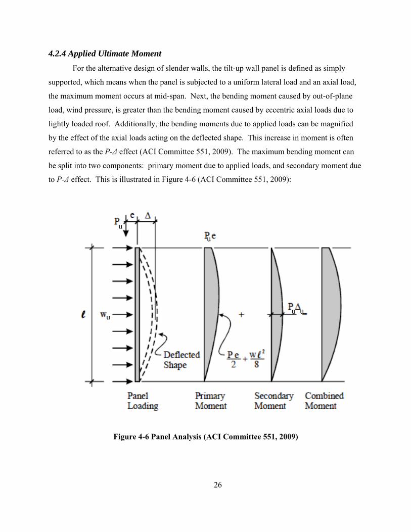
4.2.4 Applied Ultimate Moment
For the alternative design of slender walls, the tilt-up wall panel is defined as simply
supported, which means when the panel is subjected to a uniform lateral load and an axial load,
the maximum moment occurs at mid-span. Next, the bending moment caused by out-of-plane
load, wind pressure, is greater than the bending moment caused by eccentric axial loads due to
lightly loaded roof. Additionally, the bending moments due to applied loads can be magnified
by the effect of the axial loads acting on the deflected shape. This increase in moment is often
referred to as the P-Δ effect (ACI Committee 551, 2009). The maximum bending moment can
be split into two components: primary moment due to applied loads, and secondary moment due
to P-Δ effect. This is illustrated in Figure 4-6 (ACI Committee 551, 2009):
26
u u
u u u
Figure 4-6 Panel Analysis (ACI Committee 551, 2009)

The following calculation generates the maximum factored applied primary moment at midspan
due to lateral and eccentric axial loads, not including P-Δ effects:
2
8 2u ua ccc
uaw l P eM = + Equation 4-14
where wu is the factored uniform lateral load, lc is the unbraced length, Pua is the factored applied
axial load, and ecc is the eccentricity of the factored applied axial load on the panel. Essentially,
the primary moment developed in the tilt-up panel occurs due to the following loads (ACI
Committee 551, 2009):
• eccentric axial loads
• out-of-plane lateral loads
• initial lateral deflections
The maximum combined moment at mid-span of the panel is the primary moment plus the
secondary moment. To account for the axial loads acting on the deflected shape, ACI 318-08
Section 14.8.3 provides the following relationship:
u ua uM M P u= + Δ Equation 4-15 (ACI Equation 14-4)
Two approaches to determine the maximum combined moment of the section are direct method
and an iterative approach. The direct calculation is based on the moment magnifier method
whereas an iterative process calculates the incremental increases in moment and deflection due
to P-Δ effects until convergence or equilibrium is reached.
4.2.4.1 Moment Magnifier Method
The alternative design of slender walls in Section 14.8 of ACI 318-08 uses the moment
magnifier method to determine the maximum combined moment of the wall element using the
following equation:
251(0.75)48
uau
u c
c cr
MM PE I
=−
Equation 4-16
(ACI Equation 14-6) 27

The moment magnifier method used for slender wall elements is very similar to that used to
account for slenderness effects in compression members or columns. For tilt-up panels, the
panel is considered to be simply supported with uniform lateral load acting on the element.
Given the limitations of the slender wall design, maximum moment (Mmax) and deflection (Δmax)
will occur at mid-height and are defined as follows:
2
8u c
uwM =
Equation 4-17
25384
u cu
c e
wE I
Δ =
Equation 4-18
Substituting Equation 4-17 into Equation 4-18 gives the relation between maximum moment and
deflection:
2548
u cu
c e
ME I
Δ =
Equation 4-19
Furthermore, substituting Equation 4-19 into Equation 4-15 and solving for the maximum
moment yields:
25148
uau
u c
c e
MM PE I
=−
Equation 4-20
Test results published in Test Report on Slender Walls and further research by the 2005 Slender
Wall Task Group, show that the section stiffness of EcIe can be taken as the cracked section
stiffness EcIcr (ACI Committee 551, 2009). Thus, the cracked moment of inertia is defined as:
28

32( )( )
3w
cr secI n A d c= − +
Equation 4-21
For a cracked section, the concrete is in compression and reinforcing steel is in tension. In
ultimate strength design, the section is assumed to have cracked, and therefore, the tensile force
in the concrete is transferred to the steel. The factor n is a dimensionless ratio of the moduli of
elasticity of steel to concrete and is defined as follows:
s
c
EnE
=
Equation 4-22
The concrete section stiffness is assumed to be constant over the entire height of the panel (ACI
Committee 551, 2009). Lastly, the reduction factor of 0.75 in Equation 4-16, accounts for the
variability in the stiffness of the section due to material properties and construction.
4.2.4.2 Iteration Method
The second approach in determining the maximum moment and deflection at mid-height
of the panel is by a simple iterative process whereby the initially calculated applied factored
primary moment from Equation 4-14 determines the deflection from the following expression:
25(0.75)48
u cu
c cr
ME I
Δ =
Equation 4-23
The maximum moment due to P-Δ effects is determined when the necessary values substitute
into Equation 4-15. This process is repeated until both the maximum moment and deflection
converge.
4.2.5 Service Load Deflection
In addition to satisfying the strength requirement for combined flexure and axial load at
midspan of the panel, engineers must also satisfy the service load deflection requirement such
that maximum deflection due to service loads cannot exceed ℓc/150 as defined in Section 14.8.4
of ACI 318-08.
29

Before the ACI-SEAOSC Task Committee on Slender Walls, building codes limited the
ratio of height to thickness (h/t) of slender walls (Athey, 1982). However, the committee’s test
results showed that despite the h/t ratios, the wall panels had more than enough strength for
lateral loads while experiencing severe deflections. Nevertheless, very large deflections could
result in a panel that is too flexible and perhaps permanently deforms. Therefore, SEAOSC
developed service level deflection equations for the load-deflection curve based on the original
test results.
25 for 48
a cs a c
c g
MrM M
E IΔ = <
Equation 4-24
( ) for a cr
s cr n cr a crn cr
M M M MM M
−⎛ ⎞Δ = Δ + Δ −Δ >⎜ ⎟−⎝ ⎠ Equation 4-25
Based on a cracking moment with a modulus of rupture as follows:
5 'cr cM f= Equation 4-26
These equations were the basis for the slender wall provisions first incorporated into the 1987
Supplement to the Uniform Building Code (UBC) (Lawson, 2007).
Prior to ACI 318-08, service load deflections for wall panels were calculated using the
effective moment of inertia (also known as Branson’s equation) defined in Section 9.5.2.3.
3 3
1cr cre g
a a
M McrI I I
M M⎡ ⎤⎛ ⎞ ⎛ ⎞= + −⎢ ⎥⎜ ⎟ ⎜ ⎟
⎝ ⎠ ⎝ ⎠⎢ ⎥⎣ ⎦ Equation 4-27
While the traditional value for modulus of rupture in ACI 318, defined by Equation 3-3, remains
unchanged, the 2008 edition of ACI 318 uses revised deflection equations to better reflect the
original test data for slender walls.
30

for (2 / 3)a
s cr a crcr
M M MM
⎛ ⎞Δ = Δ ≤⎜ ⎟⎝ ⎠
Equation 4-28
( )(2 / 3)(2 / 3) (2 / 3) for (2 / 3)
(2 / 3)a cr
s cr n cr a crn cr
M M M MM M
⎛ ⎞−Δ = Δ + Δ − Δ >⎜ ⎟−⎝ ⎠
Equation 4-29
where
2548
cr ccr
c g
ME I
Δ =
Equation 4-30
2548
n cn
c cr
ME I
Δ =
Equation 4-31
The use of the (2/3) factor reflects the difference in cracking moment based on the modulus of
rupture defined in Equation 4-26 and the traditional value used in ACI 318. Ultimately, ACI
318-08 revisions conservatively underestimate the cracking moment by 16% on average
(Lawson, 2007). Finally, the maximum moment due to service loads (Ma) is obtained by
iteration of deflections, similar to the process defined in Section 4.2.4.2.
4.2.6 Minimum Horizontal Reinforcing
To ensure minimum ductility, the minimum ratio of horizontal reinforcement area to
gross concrete area (ρt) shall be as stated in Section 14.3.3 of ACI 318-08:
(a) 0.0020 for deformed bars not larger than No. 5 with yield strength, fy, not less than
60,000 psi
(b) 0.0025 for other deformed bars
(c) 0.0020 for welded wire reinforcement not larger than W31 or D31
The reinforcing accounts for temperature and shrinkage, and for panels used as a shear wall,
shear reinforcing is typically required. However, such reinforcing is outside the scope for this
report.
31

32
CHAPTER 5 - Solid Panel Design Example
For clarity, this chapter provides the design process for the vertical reinforcement for a
solid panel using the alternative design of slender walls. Furthermore, the analysis of vertical
reinforcement in tilt-up panels is a trial and error process for calculating the panel moment
strength based on an assumed effective area of tension reinforcement (ACI Committee 551,
2009).
5.1 Panel Design Properties Panel width = 24’-0” f’c = 4,000 psi
Panel height = 34’-0” fy = 60,000 psi
Unbraced length = 32’-0” γc = 150 pcf (normal weight concrete)
Parapet = 2’-0” fr = 474 psi (Equation 3-3)
“d” (tensile steel) = 3. 625” Ec = 3605 ksi (Equation 3-1)
n = 8.044 (Equation 4-22)

Figure 5-1 illustrates the geometry of the panel with no openings. Conservatively, wind
forces are neglected in this study. These forces would decrease the moment at mid-height of the
panel.
Figure 5-1 Solid Panel Geometry
33
Figure 5-2 illustrates the cross section of the panel.

Figure 5-2 Solid Panel Cross Section
The depth of the reinforcement is labeled to reflect the heights achieved in construction. The
chair heights are increments of ¼’’; and depending on the vertical bar size, two varying depth’s
can result. Therefore, it is conservative to use the smaller distance for design calculations.
Finally, the design should consider ‘suction’ and ‘pressure’ load due to wind.
The panel has eccentric axial load from six roof joists assumed to bear on the face of the
panel in addition to the wind pressure (lateral load); accordingly, the following loading can be
verified in Appendix A:
PDL = 5.76k (20psf)
P(Lr or S) = 7.69k(20psf)
ecc = 5.125”
Wind = 24 psf (90mph wind speed)
This report assumes an eccentricity of ½ the panel thickness plus 1.5”, suggesting a minimum
eccentricity of ½ the panel thickness (ACI Committee 551, 2009). Ultimately, the bearing
condition is determined based on the roof framing design. Figure 5-3 shows a typical joist to
panel connection.
34

Figure 5-3 Joist to Panel Connection
5.2 Load Case 1 (C&C) This section addresses the first of the three load combinations discussed in Section 4.2.1:
1.2D + 1.6(Lr or S) + 0.8W Equation 5-1
The ultimate applied axial load (excluding self-weight) derives from the load case:
Pua = 1.2(PDL) + 1.6(P(Lr or S)) + 0.8W Equation 5-2
Pua = 1.2(5.76k) + 1.6(7.69k)
Pua = 19.2k
The design should account for the effect of panel self-weight since it contributes significantly to
the P-Δ moment, although only the weight above the mid-height of the panel is considered since
the maximum moment is said to act at the mid-span. Next, a panel thickness of 7.25” (lc/53) was
derived by trial and error, while the suggested minimum thickness is (1/50) of the unbraced
length for a single mat of reinforcement or (1/65) of the unbraced length for a double mat (ACI
Committee 551, 2009). The ultimate axial load including self-weight above mid-span is:
Pum= Pua + 1.2(panel weight above CL) Equation 5-3
35
panel weight above CL =
( ) ( )7.25 3224 150 212 21
1000 /
in ftft pcf finft
k lb
⎛ ⎞⎜ ⎟
t⎡ ⎤⎛ ⎞⎜ ⎟ +⎜ ⎟⎢ ⎥⎝ ⎠⎜ ⎟ ⎣ ⎦⎜ ⎟⎝ ⎠ = 39.2k
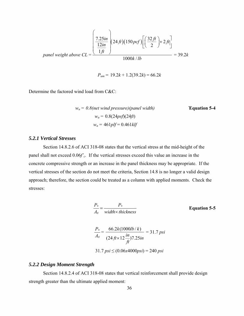
Pum = 19.2k + 1.2(39.2k) = 66.2k
Determine the factored wind load from C&C:
wu = 0.8(net wind pressure)(panel width) `Equation 5-4
wu = 0.8(24psf)(24ft)
wu = 461plf = 0.461klf
5.2.1 Vertical Stresses
Section 14.8.2.6 of ACI 318-08 states that the vertical stress at the mid-height of the
panel shall not exceed 0.06f’c. If the vertical stresses exceed this value an increase in the
concrete compressive strength or an increase in the panel thickness may be appropriate. If the
vertical stresses of the section do not meet the criteria, Section 14.8 is no longer a valid design
approach; therefore, the section could be treated as a column with applied moments. Check the
stresses:
u u
g
P PA width thickness
=×
Equation 5-5
u
g
PA
= 66.2 (1000 / )
(24 12 )7.25
k lb kinft ift
× n = 31.7 psi
31.7 psi ≤ (0.06x4000psi) = 240 psi
5.2.2 Design Moment Strength
Section 14.8.2.4 of ACI 318-08 states that vertical reinforcement shall provide design
strength greater than the ultimate applied moment: 36

φMn ≥ Mcr Equation 5-6 (ACI Equation 14-2)
Next, define the cracking moment by Equation 4-11:
3
12g
bhI =
Equation 5-7
( )3(24 12 ) 7.25
12g
inft iftI
×=
n
Ig = 9,146 in4
( )4(474 ) 9,1467.25
2
crpsi in
M in=
1,195,918 100crM lb in k ft= − = −
To determine the moment strength of the section trial and error the following for an area of
tensile reinforcement:
Use a single-layer #6 bar spaced at 10.125” on center
Account for clear cover of ¾” and center of bar spacing, total number of bars:
24 12 (2 0.75 ) (.75 )
10.125
inft inft
in
⎡ ⎤× − × −⎢ ⎥
⎣ ⎦in
= 28.2 bars
Use (29) #6 bars at 10.125” on center, total area of steel, As: 2 229 (0.44 ) 12.76sA bars in in= × =
The minimum flexural reinforcement per Section 10.5.1 of ACI 318-08 calls for the area of steel
provided being not less than the maximum value obtained below:
min
3 'cy
ff
ρ =
Equation 5-8
min3 4,00060,000
psipsi
ρ =
37

min 0.00316ρ =
min
200
yfρ =
Equation 5-9
min200
60,000 psiρ =
min 0.00333ρ = Governs
compare the actual reinforcement ratio with the minimum:
secs
w
Ab d
ρ = Equation 5-10
2
sec12.761224 (3.625 )1
ininft ift
ρ =⎛ ⎞
×⎜ ⎟⎝ ⎠
n= 0.0122
0.0122 ≥ 0.00333
(reinforcement ratio meets the minimum reinforcement ratio requirement)
Check the minimum ratio of vertical reinforcement area to gross concrete area per Section 14.3.2
of ACI 318-08:
sec
s
w
Ab t
ρ =
Equation 5-11
2
sec12.76
12(24 (7.25 )1
ininft ift
ρ =⎛ ⎞
×⎜ ⎟⎝ ⎠
n
sec 0.006ρ = ≥ 0.0015
(reinforcement ratio meets the minimum reinforcement ratio requirement)
Next, determine the effective area of steel defined by Equation 4-6:
38

Ase = 2 (66.2 )(7.25 )12.762(60 )(3.625 )
k ininksi in
⎛ ⎞+ ⎜ ⎟⎝ ⎠
Ase = 13.86 in2
Use the equivalent rectangular stress block, the depth of the stress block, as defined by Equation
4-10:
a = 213.86 (60 )
120.85(4 )241
in ksiinksi ftft
⎛ ⎞⎜ ⎟⎝ ⎠
a =0.849 in
The alternative design of slender walls method can be used when the section is considered
tension-controlled as addressed in Section 9.3.2 of ACI 318-08. Both criteria addressed in
Section 4.2.2 can be used to verify that the section is indeed tension-controlled. For concrete
with a compressive strength of 4,000 psi, Section 10.2.7.3 of ACI 318-08 gives
β1 = 0.85, therefore:
1
acβ
=
Equation 5-12
0.8490.85
inc =
c = 1.0 in
Next, check whether the section is tension-controlled:
1.0 0.276 0.3753.625t
cd
= = ≤
(tension-controlled, φ=0.90)
Alternatively, use similar triangles and check the strain values:
0.003 0.003t
tdc
ε ⎛ ⎞= −⎜ ⎟⎝ ⎠
Equation 5-13
3.6250.003 0.0031.0t
inin
ε ⎛ ⎞= −⎜ ⎟⎝ ⎠
0.00788 0.005tε = ≥
39

(tension-controlled, Ф=0.90)
Use Equation 4-5 to determine the design moment strength:
2 0.849(0.9)(13.86 )(60 ) 3.6252
ninM in ksi inφ ⎛ ⎞= −⎜ ⎟
⎝ ⎠
2,395.4 199.6nM k in k ftφ = − = −
Finally, compare design moment strength with the cracking moment:
199.6 k-ft ≥ 100 k-ft
5.2.3 Applied Moment
Given the two methods discussed in Section 4.2.4 for obtaining the applied moment in
the panel, the factored applied moment from Equation 4-14 is as follows:
2119.2 *5.125 *0.461 *(32 ) 12
8 2ua
ftk inklf ft inM
⎛ ⎞⎜ ⎟⎛ ⎞
= + ⎜ ⎟⎜ ⎟⎝ ⎠ ⎜ ⎟
⎝ ⎠
63.1 757.3uaM k ft k in= − = −
This is only the primary factored moment due to applied wind loading; however, the total
combined moment on the section includes the primary moment and the secondary moment due to
P-Δ effects. Notably, Figure 5-4 depicts the moment diagram of the panel and typically the
parapet is neglected in the calculation of the applied moment because it reduces the applied
moment.
40

Figure 5-4 Moment Diagram
First, the study evaluated the moment magnifier method and determined the cracked moment of
inertia from Equation 4-21 and Equation 4-22:
3
2 2
24 *12 (1.0 )8.044(13.86 )(3.625 1.0 )
3cr
inft ift
I in in in
⎛ ⎞⎜ ⎟⎝ ⎠= − +
n
4864crI in=
The maximum moment calculated by the direct method follows:
2
4
757.3
125(66.2 ) 32 *1
1(0.75)(48)(3605 )(864 )
uk inM
ink ftft
ksi in
−=
⎛ ⎞⎛ ⎞⎜ ⎟⎜ ⎟⎜ ⎟⎝ ⎠− ⎜ ⎟⎜ ⎟⎜ ⎟⎝ ⎠
1,341 111.8uM k in k ft= − = −
The maximum moment can also be obtained by an iterative process based on Equation 4-15:
u ua uM M P u= + Δ
The first iteration will begin with the factored applied moment already found from 41

Equation 4-14. Next, Equation 4-23 determines the deflection due to this moment: 2
4
5(757.3 ) 32 12
(0.75)(48)(3605 )(864 )u
ink in ftft
ksi in
⎛ ⎞− ×⎜ ⎟
⎝ ⎠Δ =
4.98u inΔ =
Therefore, the first iteration gives the following maximum moment using Equation 4-15:
757.3 (66.2 )(4.98 )uM k in k in= − +
1,087uM k in= −
Continuing the iterative process using Equation 4-15, generates a ‘new’ deflection based on the
‘new’ maximum moment found. The iteration process should continue until the maximum
moment and deflection both converge. The end result of the maximum moment should be very
close to the value obtained from the direct method as shown below: 2
4
5(1,339 ) 32 12
(0.75)(48)(3605 )(864 )u
ink in ftft
ksi in
⎛ ⎞− ×⎜ ⎟
⎝ ⎠Δ =
8.80u inΔ =
757.3 (66.2 )(8.80 )uM k in k in= − +
1,340 111.6uM k in k ft= − = −
Only one of the methods discussed would need to determine the maximum moment on the panel;
however, for comparison the report shows both methods. For strength requirements, the
following relationship needs to be satisfied:
φMn ≥ Mu
199.6k-ft ≥ 111.6k-ft
(design strength is greater than required moment)
5.2.4 Service Load Deflection
Now that the panel satisfies strength requirements, it must satisfy serviceability
requirements too. Section 14.8.4 of ACI 318-08 states that the maximum out-of-plane deflection
due to service loads, including P-Δ effects, shall not exceed the following:
42

150c
allowΔ =
An iterative process similar to that used for obtaining the applied moment will determine the
maximum deflection of the panel due to service loads. To begin, the maximum moment at mid-
height of the panel due to service loads derives from Equation 4-14:
21(5.76 7.69 ) 5.12524 24 (32 ) 12
1,000 281
sa
ftk k inpsf ft ft inM lbsk
⎛ ⎞ ⎛ + × ×⎜ ⎟ ⎜× ×= +⎜ ⎟ ⎜⎜ ⎟ ⎜×⎝ ⎠ ⎝
⎞⎟⎟⎟⎠
76.6 919.2saM k ft k in= − = −
This moment due to service loads is compared to (2/3)Mcr to determine which Δs equation is
appropriate.
2 (100 ) 673
k ft k ft− = −
76.6 67k ft k ft− > − therefore use Equation 4-29
From Equation 4-30: 2
4
12 125 100 * 32 *1 1
48(3605 )(9,146 )cr
in ink ft ftft f
ksi in
⎛ ⎞⎛−⎜ ⎟⎜
⎝ ⎠⎝Δ =t⎞⎟⎠
0.56cr inΔ =
From Equation 4-31: 2
4
199.6 12 125 320.90 1 1
48(3605 )(864 )n
k ft in inftft f
ksi in
⎛ ⎞⎛−× ×⎜ ⎟⎜
⎝ ⎠⎝Δ =t⎞⎟⎠
13.12n inΔ =
Use Equation 4-29 as determined above:
[ ]76.6 (2 / 3)(100 )(2 / 3)(0.56 ) 13.12 (2 / 3)(0.56 )199.6 (2 / 3)(100 )0.9
sk ft k ftin in ink ft k ft
⎛ ⎞⎜ ⎟− − −
Δ = + −⎜ ⎟−⎜ ⎟− −⎝ ⎠
1.20s inΔ =
43

Now the iterative process begins:
919.2 (39.2 5.76 7.69 )(1.20 )aM k in k k k in= − + + +
982.4 81.9saM k in k ft= − = −
Determine deflection based on a ‘new’ maximum service moment:
[ ]81.9 (2 / 3)(100 )(2 / 3)(0.56 ) 13.12 (2 / 3)(0.56 )199.6 (2 / 3)(100 )0.9
sk ft k ftin in ink ft k ft
⎛ ⎞⎜ ⎟− − −
Δ = + −⎜ ⎟−⎜ ⎟− −⎝ ⎠
1.63s inΔ =
Calculate the ‘new’ maximum moment due to service load:
919.2 (39.2 5.76 7.69 )(1.63 )aM k in k k k in= − + + +
1,005 83.8aM k in k ft= − = −
Continue iteration until convergence:
1.79s inΔ =
1,013 84.4aM k in k ft= − = −
1.84s inΔ =
1,016.2 84.7aM k in k ft= − = −
1.86s inΔ =
1,017.3 84.8aM k in k ft= − = −
1.87s inΔ =
1,017.7 84.8aM k in k ft= − = −
1.87s inΔ =
Once the maximum moment and deflection both converge, compare the maximum deflection due
to service loads to the allowable deflection.
1232 *1 2.56
150allow
inftft inΔ = =
1.87in ≤ 2.56in
(deflection due to service load meets maximum allowable deflection requirement)
44

These calculations show the strength and serviceability requirements per Section 14.8 of ACI
318-08 have both been satisfied for Load Case 1. Evaluation of Load Case 2 and Load Case 3
for all panel scenarios can be found in Appendix C.
5.3 Minimum Horizontal Reinforcement To satisfy minimum horizontal reinforcement requirements defined in Section 14.3.3 of
ACI 318-08:
, min120.002(7.25 ) 34 *s
inA in ftft
⎛ ⎞= ⎜ ⎟
⎝ ⎠
2, min 5.916sA in=
# of bars =2
2
5.916 29.580.2
inin
=
Therefore provide 30-#4 bars for horizontal reinforcement.
5.4 Summary Figure 5-5 shows that for the given loading, a 7.25” thick panel with vertical
reinforcement of (29)-#6 bars at 10.125” on center, satisfied both strength and serviceability
requirements per the code and load combinations. While the design process is tedious and
requires several trial and error calculations, the goal as a designer is to achieve the most
economical design while first ensuring safety. Finally, design results for greater wind speeds and
unbraced length are shown in Table 7-1 and Table 7-2.
45

Figure 5-5 Solid Panel Reinforcement Layout
46

CHAPTER 6 - Panel with Opening Design Example
For clarity, this chapter will provide the design process for vertical reinforcement for a
panel with a square opening in the middle using the alternative design of slender walls. An
opening placed in the middle of the panel is of interest because maximum moment and deflection
occurs at or near mid-height of the panel. Tilt-up panels with an opening does not have a
constant cross-section over the height of the panel; therefore, to account for the effect of the
opening, the design section is termed the jamb or ‘design strip’. Figure 6-1 illustrates the design
approach for a panel with an opening centered in the middle. The ‘design strips’ are to resist
tributary wind lateral loads and vertical loads tributary to the strips (Tilt-Up Concrete
Association, 2004).
Figure 6-1 Design Model for Panel with Opening
47

48
6.1 Panel Design Properties Panel width = 24’-0” f’c = 4,000 psi
Panel height = 34’-0” fy = 60,000 psi
Unbraced length = 32’-0” γc = 150 pcf (normal weight concrete)
Parapet = 2’-0” fr = 474 psi (Equation 3-3)
“d” (tensile steel) = 5.5” Ec = 3605 ksi (Equation 3-1)
Square Opening = 12’-0”x12’-0”
n = 8.044 (Equation 4-22)

Figure 6-2 illustrates the geometry of the panel with a 12’ x 12’ opening.
Figure 6-2 Panel with Opening Geometry
Figure 6-3 illustrates the cross-section of the panel. Trial and error of reinforcement
configurations determined two layers of steel for adequate strength and deflection control.
49

Figure 6-3 Panel with Opening Cross Section
The eccentric axial load and out-of-plane wind pressure remains the same as the previous
example. Due to symmetry of the panel, the ‘design strips’ are equivalent, and therefore the
vertical reinforcement will be the same for both panel legs on either side of the opening. Based
on the tributary concept, the lateral wind pressure of 24 psf is distributed around the opening to
the panel legs.
panel leg width (design strip) = 1 (24 12 ) 62
ft ft ft− =
tributary width = 126 12ft 2ft ft+ =
6.2 Load Case 1 (C&C) This section addresses the first of the three load combinations discussed in Section 4.2.1.
1.2D + 1.6(Lr or S) + 0.8W Equation 6-1
The ultimate applied axial load (excluding self-weight) derives from the load case and considers
only three joists contributing to one panel leg:
Pua = 1.2(PDL) + 1.6(P(Lr or S)) + 0.8W Equation 6-2
Pua = 1.2(3x0.96k) + 1.6(3x1.28k)
Pua = 9.61k
50
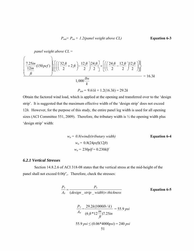
Pum= Pua + 1.2(panel weight above CL) Equation 6-3
panel weight above CL =
7.25 32 12 24 24 12 12(150 ) 212 2 2 2 2 2 2
1,000
in ft ft ft ft ft ftpcf ftinft
lbsk
⎛ ⎞⎜ ⎟⎧ ⎫⎡ ⎤ ⎡⎛ ⎞ ⎛⎪ ⎪⎛ ⎞ ⎛ ⎞⎜ ⎟ + − + −⎨ ⎬⎜ ⎟ ⎜ ⎟⎢ ⎥ ⎢⎜ ⎟ ⎜⎝ ⎠ ⎝ ⎠⎜ ⎟ ⎝ ⎠ ⎝⎪ ⎪⎣ ⎦ ⎣⎩ ⎭⎜ ⎟⎝ ⎠
⎤⎞⎥⎟⎠⎦
= 16.3k
Pum = 9.61k + 1.2(16.3k) = 29.2k
Obtain the factored wind load, which is applied at the opening and transferred over to the ‘design
strip’. It is suggested that the maximum effective width of the ‘design strip’ does not exceed
12h. However, for the purpose of this study, the entire panel leg width is used for all opening
sizes (ACI Committee 551, 2009). Therefore, the tributary width is ½ the opening width plus
‘design strip’ width:
wu = 0.8(wind)(tributary width) Equation 6-4
wu = 0.8(24psf)(12ft)
wu = 230plf = 0.230klf
6.2.1 Vertical Stresses
Section 14.8.2.6 of ACI 318-08 states that the vertical stress at the mid-height of the
panel shall not exceed 0.06f’c. Therefore, check the stresses:
( _ _ )
u u
g
P PA design strip width thickness
=×
Equation 6-5
u
g
PA
=29.2 (1000 / )
(6 *12 )7.25
k lb kinft ift
n = 55.9 psi
55.9 psi ≤ (0.06*4000psi) = 240 psi 51

6.2.2 Design Moment Strength
Section 14.8.2.4 of ACI 318-08 states that vertical reinforcement shall provide design strength greater than or equal to the cracking moment: φMn ≥ Mcr Equation 6-6
(ACI Equation 14-2)
The cracking moment is defined by Equation 4-11:
3
12g
bhI =
Equation 6-7
( )3(6 *12 ) 7.25
12g
inft iftI =
n
Ig = 2,286 in4
( )4(474 ) 2, 2867.25
2
crpsi in
M in=
298,914 25crM lb in k ft= − = −
To determine the moment strength of the section, trial and error the following area of tensile
reinforcement :
Use two-layers of #4 bar spaced at 3. 25” on center each face
Account for clear cover of ¾’’ and center of bar spacing, total number of bars:
6 12 (2 0.75 ) (0.5 )
3.25
inft inft
in
⎛ ⎞⎡ ⎤× − × −⎜ ⎟⎢ ⎥
⎣ ⎦⎜ ⎟⎜ ⎟⎜ ⎟⎝ ⎠
in
2
= 21.5 bars
Use (22)-#4 bars at 3.625” on center each face, total area of steel, As: 222 (0.2 ) 4.4sA bars in in= × = each face
Finally, checking the minimum ratio of vertical reinforcement area to gross concrete area per
Section 14.3.2 of ACI 318-08:
52
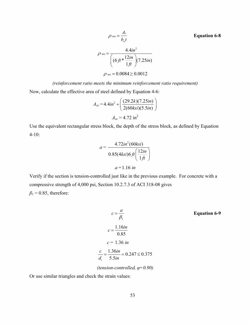
sec
s
w
Ab t
ρ =
Equation 6-8
2
sec4.412(6 * (7.25 )1
ininft ift
ρ =⎛ ⎞⎜ ⎟⎝ ⎠
n
sec 0.0084ρ = ≥ 0.0012
(reinforcement ratio meets the minimum reinforcement ratio requirement)
Now, calculate the effective area of steel defined by Equation 4-6:
Ase = 2 (29.2 )(7.25 )4.42(60 )(5.5 )
k ininksi in
⎛ ⎞+ ⎜ ⎟⎝ ⎠
Ase = 4.72 in2
Use the equivalent rectangular stress block, the depth of the stress block, as defined by Equation
4-10:
a = 24.72 (60 )
120.85(4 )61
in ksiinksi ftft
⎛ ⎞⎜ ⎟⎝ ⎠
a =1.16 in
Verify if the section is tension-controlled just like in the previous example. For concrete with a
compressive strength of 4,000 psi, Section 10.2.7.3 of ACI 318-08 gives
β1 = 0.85, therefore:
1
acβ
=
Equation 6-9
1.160.85
inc =
c = 1.36 in
1.36 0.247 0.3755.5t
c ind in
= = ≤
(tension-controlled, φ=0.90)
Or use similar triangles and check the strain values:
53

0.003 0.003t
tdc
ε ⎛ ⎞= −⎜ ⎟⎝ ⎠
Equation 6-10
5.50.003 0.0031.36t
inin
ε ⎛ ⎞= −⎜ ⎟⎝ ⎠
0.009 0.005tε = ≥
(tension-controlled, φ=0.90)
Use Equation 4-5 to determine the nominal moment strength:
2 1.16(0.9)(4.72 )(60 ) 5.52
ninM in ksi inφ ⎛ ⎞= −⎜ ⎟
⎝ ⎠
1, 254 104.5nM k in k ftφ = − = −
Compare nominal moment strength with the cracking moment:
104.5 k-ft ≥ 25 k-ft (OK)
6.2.3 Applied Moment
Recall the two methods discussed in Section 4.2.4 for obtaining the applied moment in
the panel. First, consider the factored applied moment from Equation 4-14:
219.61 *5.5 *0.230 *(32 ) 12
8 2ua
ftk inklf ft inM
⎛ ⎞⎜ ⎟⎛ ⎞
= + ⎜ ⎟⎜ ⎟⎝ ⎠ ⎜ ⎟
⎝ ⎠
31.6 379.2uaM k ft k in= − = −
Then evaluate the moment magnifier method using the cracked moment of inertia found from
Equation 4-21 and Equation 4-22:
3
2 2
6 *12 (1.36 )8.044(4.72 )(5.5 1.36 )
3cr
inft ift
I in in in
⎛ ⎞⎜ ⎟⎝ ⎠= − +
n
4711crI in=
Then calculate the maximum moment calculated by the direct method:
54

2
4
379.2
125(29.2 ) 32 *11
(0.75)(48)(3605 )(711 )
uk inM
ink ftft
ksi in
−=
⎛ ⎞⎛ ⎞⎜ ⎟⎜ ⎟⎜ ⎟⎝ ⎠− ⎜ ⎟⎜ ⎟⎜ ⎟⎝ ⎠
494.6 41.2uM k in k ft= − = −
The maximum moment can also be obtained by an iterative process using Equation 4-15 as the
base equation:
u ua uM M P u= + Δ
The first iteration will begin with the factored applied moment from Equation 4-14. The
deflection due to this moment is found by Equation 4-23. 2
4
5(379.2 ) 32 *12
(0.75)(48)(3605 )(711 )u
ink in ftft
ksi in
⎛ ⎞− ⎜ ⎟
⎝ ⎠Δ =
3.03u inΔ =
Therefore, the first iteration gives the following maximum moment using Equation 4-15:
379.2 (29.2 )(3.03 )uM k in k in= − +
467.7uM k in= −
Continuing the iterative process using Equation 4-15, a ‘new’ deflection will be determined
based on the ‘new’ maximum moment found. Then, the iteration process should be continued
until the maximum moment and deflection both converge. The end result of the maximum
moment should be very close to the value obtained from the direct method as shown below: 2
4
5(493.6 ) 32 *12
(0.75)(48)(3605 )(711 )u
ink in ftft
ksi in
⎛ ⎞− ⎜ ⎟
⎝ ⎠Δ =
3.94u inΔ =
379.2 (29.2 )(3.94 )uM k in k in= − +
494.2 41.2uM k in k ft= − = −
Only one of the methods would be necessary to determine the maximum moment on the panel,
but for comparison, both methods were shown. For strength requirements, the following
relationship needs to be satisfied: 55

φMn ≥ Mu
104.5k-ft ≥ 41.2k-ft
(design moment strength is greater than required moment)
6.2.4 Service Load Deflection
Now that the panel satisfies strength requirements, check if the panel satisfies
serviceability requirements too. Section 14.8.4 of ACI 318-08 states that the maximum out-of-
plane deflection due to service loads, including P-Δ effects, shall not exceed:
150c
allowΔ =
An iterative process similar to that used for obtaining the applied moment will determine the
maximum deflection of the panel due to service loads. First, calculate the maximum moment at
mid-height of the panel due to service loads from Equation 4-14:
213 (0.96 1.28 ) 5.524 12 (32 ) 12
1,000 281
a
ftk k inpsf ft ft inM lbsk
⎛ ⎞ ⎛ × + × ×⎜ ⎟ ⎜× ×= +⎜ ⎟ ⎜⎜ ⎟ ⎜×⎝ ⎠ ⎝
⎞⎟⎟⎟⎠
38.4 460.8saM k ft k in= − = −
This moment due to service loads is compared to (2/3)Mcr to determine which Δs equation is
appropriate.
2 (25 ) 16.73
k ft k ft− = −
38.4 16.7k ft k ft− > − therefore use Equation 4-29
From Equation 4-30: 2
4
12 125 25 * 32 *1 1
48(3605 )(2,286 )cr
in ink ft ftft f
ksi in
⎛ ⎞⎛−⎜ ⎟⎜
⎝ ⎠⎝Δ =t⎞⎟⎠
0.56cr inΔ =
From Equation 4-31:
56

2
4
104.5 12 125 * 32 *0.90 1 1
48(3605 )(711 )n
k ft in inftft f
ksi in
⎛ ⎞⎛−⎜ ⎟⎜⎝ ⎠⎝Δ =
t⎞⎟⎠
8.35n inΔ =
Use Equation 4-29 as determined above:
[ ]38.4 (2 / 3)(25 )(2 / 3)(0.56 ) 8.35 (2 / 3)(0.56 )104.5 (2 / 3)(25 )0.9
sk ft k ftin in ink ft k ft
⎛ ⎞⎜ ⎟− − −
Δ = + −⎜ ⎟−⎜ ⎟− −⎝ ⎠
2.11s inΔ =
Now, the iterative process, like before, can begin:
460.8 (16.3 3*(0.96 1.28 ))(2.11 )aM k in k k k in= − + + +
509.4 42.5aM k in k ft= − = −
Calculate deflection based on the ‘new’ maximum service moment:
[ ]42.5 (2 / 3)(25 )(2 / 3)(0.56 ) 8.35 (2 / 3)(0.56 )104.5 (2 / 3)(25 )0.9
sk ft k ftin in ink ft k ft
⎛ ⎞⎜ ⎟− − −
Δ = + −⎜ ⎟−⎜ ⎟− −⎝ ⎠
2.44s inΔ =
Determine ‘new’ maximum moment due to service load:
460.8 (16.3 3*(0.96 1.28 ))(2.44 )aM k in k k k in= − + + +
517 43.1aM k in k ft= − = −
Continue iteration until convergence:
2.49s inΔ =
517.03 43.1aM k in k ft= − = −
2.50s inΔ =
517.05 43.1aM k in k ft= − = −
Once the maximum moment and deflection both converge, compare the maximum deflection due
to service loads to the allowable deflection.
57

1232 *1 2.56
150allow
inftft inΔ = =
2.49in ≤ 2.56in
(deflection due to service load meets maximum allowable deflection requirement)
Final calculations show the strength and serviceability requirements per Section 14.8 of ACI
318-08 have both been satisfied for Load Case 1.
6.4 Minimum Horizontal Reinforcement To satisfy minimum horizontal reinforcement requirements defined in Section 14.3.3 of
ACI 318-08:
, min120.002(7.25 ) 34 *s
inA in ftft
⎛ ⎞= ⎜ ⎟
⎝ ⎠
2, min 5.916sA in=
# of bars =2
2
5.916 29.580.2
inin
=
Therefore provide 30-#4 bars for horizontal reinforcement, modifying the lengths where needed
on both sides of the opening.
58

6.5 Summary Figure 6-4 shows that for the given loading, a 7.25” thick panel with vertical
reinforcement in each panel leg of (22)-#4 bars at 3.25” on center and each face, satisfied both
strength and serviceability requirements per the code and load combinations. Recall this is only
the vertical reinforcement to be placed in the panel legs on both sides of the opening.
Meanwhile, vertical reinforcement above and below the opening shall meet the code minimum as
defined in ACI 318-08 Section 14.3.2. Finally, design results for greater wind speeds and
unbraced length are shown in Table 7-3 and Table 7-4.
Figure 6-4 Panel with Opening Reinforcement Layout
59

CHAPTER 7 - Results and Conclusions
With the Alternative Design of Slender Walls method, vertical reinforcement was
determined for tilt-up wall panels subject to axial load and out-of-plane uniform lateral wind
pressure based on wind speeds of 90 mph, 110 mph, 130 mph, and 150 mph for unbraced lengths
of 32 ft and 40 ft. Analysis was performed both for a panel with no openings and for a panel
with a square opening centered in the panel varying in size: 4 ft, 8 ft, 12 ft, and 16 ft. For
formwork purposes, panel thicknesses were of 7.25”, 9.25” and 11.25”, and vertical
reinforcement included #4, #5, and #6 bars.
Tilt-up wall panels must satisfy strength and serviceability requirements defined by ACI
318-08 Sections 14.8.3 and 14.8.4, respectively and abide by code limitations for reinforcement
requirements. The moment magnifier method presented in ACI 318-08 Section 14.8 is
considered a trial and error approach in determining the area of tension reinforcement to satisfy
strength requirements. Recall from Equation 4-15:
60
uu ua uM M P= + Δ
The maximum moment Mu can be written as:
u uu ua
b
P MM MK
= +
Furthermore, the term Kb is referred to as the panel stiffness:
2
485
u cb
u
crM E IK = =Δ
From Equation 4-5, φMn is directly proportional to the area of effective tension reinforcement,
Ase:
φMn = φAsefy(d - )
Figure 7-1 shows that the factored moment, Mu, is inversely proportional to Ase.
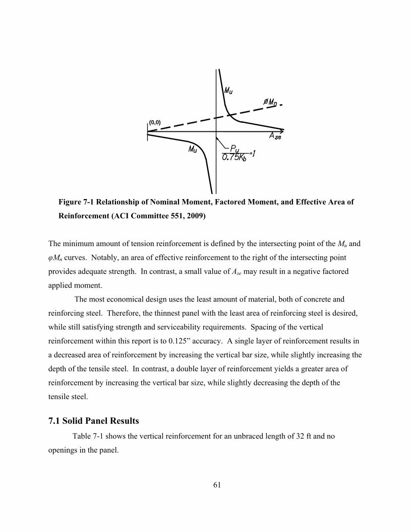
(0,0)
Figure 7-1 Relationship of Nominal Moment, Factored Moment, and Effective Area of
Reinforcement (ACI Committee 551, 2009)
The minimum amount of tension reinforcement is defined by the intersecting point of the Mu and
φMn curves. Notably, an area of effective reinforcement to the right of the intersecting point
provides adequate strength. In contrast, a small value of Ase may result in a negative factored
applied moment.
The most economical design uses the least amount of material, both of concrete and
reinforcing steel. Therefore, the thinnest panel with the least area of reinforcing steel is desired,
while still satisfying strength and serviceability requirements. Spacing of the vertical
reinforcement within this report is to 0.125” accuracy. A single layer of reinforcement results in
a decreased area of reinforcement by increasing the vertical bar size, while slightly increasing the
depth of the tensile steel. In contrast, a double layer of reinforcement yields a greater area of
reinforcement by increasing the vertical bar size, while slightly decreasing the depth of the
tensile steel.
7.1 Solid Panel Results Table 7-1 shows the vertical reinforcement for an unbraced length of 32 ft and no
openings in the panel.
61
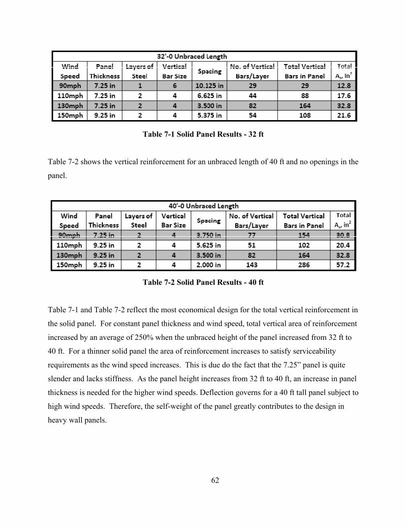
Table 7-1 Solid Panel Results - 32 ft
Table 7-2 shows the vertical reinforcement for an unbraced length of 40 ft and no openings in the
panel.
Table 7-2 Solid Panel Results - 40 ft
Table 7-1 and Table 7-2 reflect the most economical design for the total vertical reinforcement in
the solid panel. For constant panel thickness and wind speed, total vertical area of reinforcement
increased by an average of 250% when the unbraced height of the panel increased from 32 ft to
40 ft. For a thinner solid panel the area of reinforcement increases to satisfy serviceability
requirements as the wind speed increases. This is due do the fact that the 7.25” panel is quite
slender and lacks stiffness. As the panel height increases from 32 ft to 40 ft, an increase in panel
thickness is needed for the higher wind speeds. Deflection governs for a 40 ft tall panel subject to
high wind speeds. Therefore, the self-weight of the panel greatly contributes to the design in
heavy wall panels.
62

7.2 Panel with Opening Results Table 7-3 illustrates the wall panel design with different size of openings centered in the
unbraced length of 32 ft and subject to varying wind speeds.
Table 7-3 Panel with Opening Results - 32 ft
63

Table 7-4 illustrates the wall panel design with different size of openings centered in the
unbraced length of 40 ft and subject to varying wind speeds.
Table 7-4 Panel with Opening Results - 40 ft
Table 7-3 and Table 7-4 reflect the most economical design for the total vertical reinforcement in
the panel, including vertical reinforcement above and below the opening. Notably, for panels
with openings, a double layer of reinforcement is used in all panel thicknesses to satisfy strength
64

65
and serviceability requirements. As the opening size increases, more reinforcement is required
in each panel leg. However, as the opening size increases, the section where the vertical
reinforcement is to be placed is less likely to be tension-controlled. Therefore, the panel
thickness needs to be increased. For large openings and high wind speeds, no design solution
was achieved due to non-tension controlled behavior and therefore deeming ACI 318-08 Section
14.8 an invalid design approach in this case.
Through continued research, engineering of tilt-up concrete panels is becoming more
exact and therefore yielding more economical design solutions. As a design engineer, safety is
always of most importance. To ensure safe design of tilt-up panels, the Alternative Design of
Slender Walls is widely practiced. ACI 318-08 Section 14.8 is appropriate for design when
flexural tension controls the out-of-plane design of a wall.
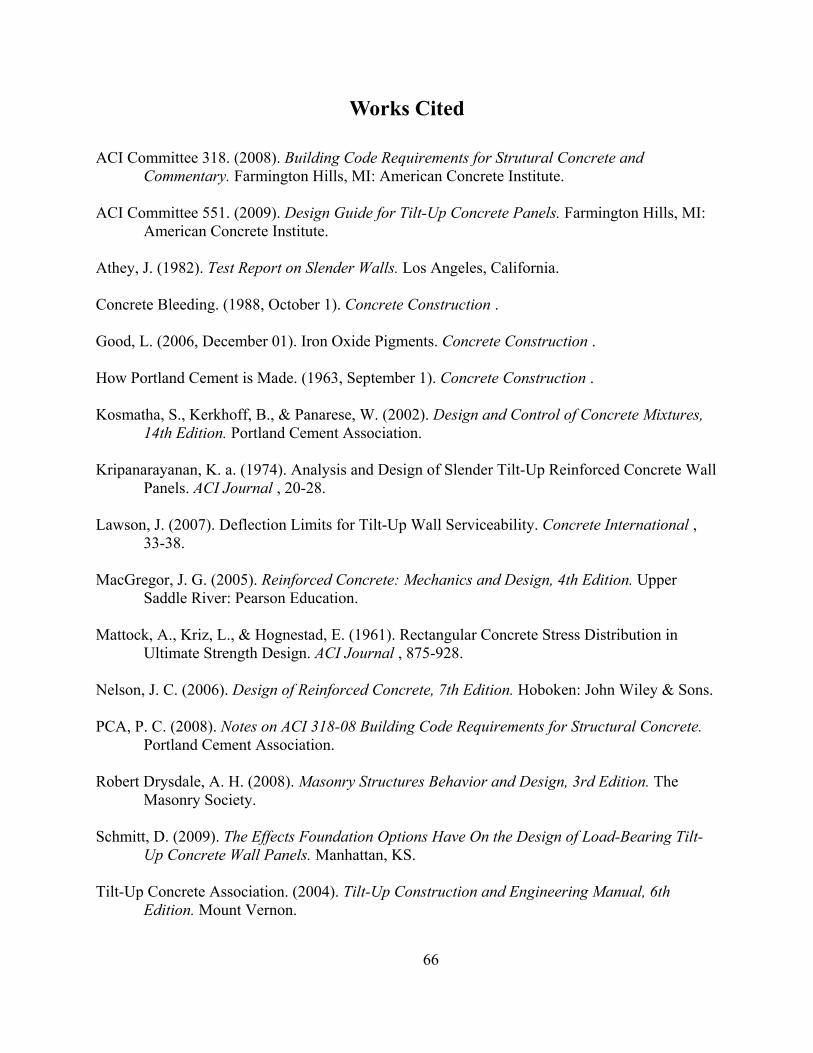
66
Works Cited
ACI Committee 318. (2008). Building Code Requirements for Strutural Concrete and Commentary. Farmington Hills, MI: American Concrete Institute.
ACI Committee 551. (2009). Design Guide for Tilt-Up Concrete Panels. Farmington Hills, MI:
American Concrete Institute. Athey, J. (1982). Test Report on Slender Walls. Los Angeles, California. Concrete Bleeding. (1988, October 1). Concrete Construction . Good, L. (2006, December 01). Iron Oxide Pigments. Concrete Construction . How Portland Cement is Made. (1963, September 1). Concrete Construction . Kosmatha, S., Kerkhoff, B., & Panarese, W. (2002). Design and Control of Concrete Mixtures,
14th Edition. Portland Cement Association. Kripanarayanan, K. a. (1974). Analysis and Design of Slender Tilt-Up Reinforced Concrete Wall
Panels. ACI Journal , 20-28. Lawson, J. (2007). Deflection Limits for Tilt-Up Wall Serviceability. Concrete International ,
33-38. MacGregor, J. G. (2005). Reinforced Concrete: Mechanics and Design, 4th Edition. Upper
Saddle River: Pearson Education. Mattock, A., Kriz, L., & Hognestad, E. (1961). Rectangular Concrete Stress Distribution in
Ultimate Strength Design. ACI Journal , 875-928. Nelson, J. C. (2006). Design of Reinforced Concrete, 7th Edition. Hoboken: John Wiley & Sons. PCA, P. C. (2008). Notes on ACI 318-08 Building Code Requirements for Structural Concrete.
Portland Cement Association. Robert Drysdale, A. H. (2008). Masonry Structures Behavior and Design, 3rd Edition. The
Masonry Society. Schmitt, D. (2009). The Effects Foundation Options Have On the Design of Load-Bearing Tilt-
Up Concrete Wall Panels. Manhattan, KS. Tilt-Up Concrete Association. (2004). Tilt-Up Construction and Engineering Manual, 6th
Edition. Mount Vernon.

Appendix A - Sample Load Calculations
67
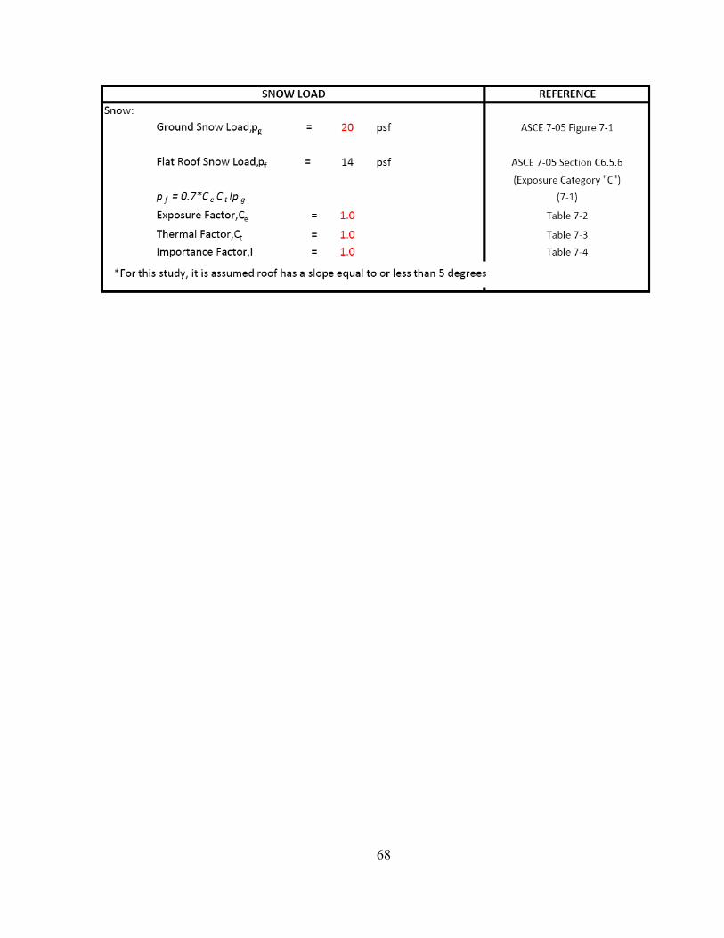
68

69

70

71
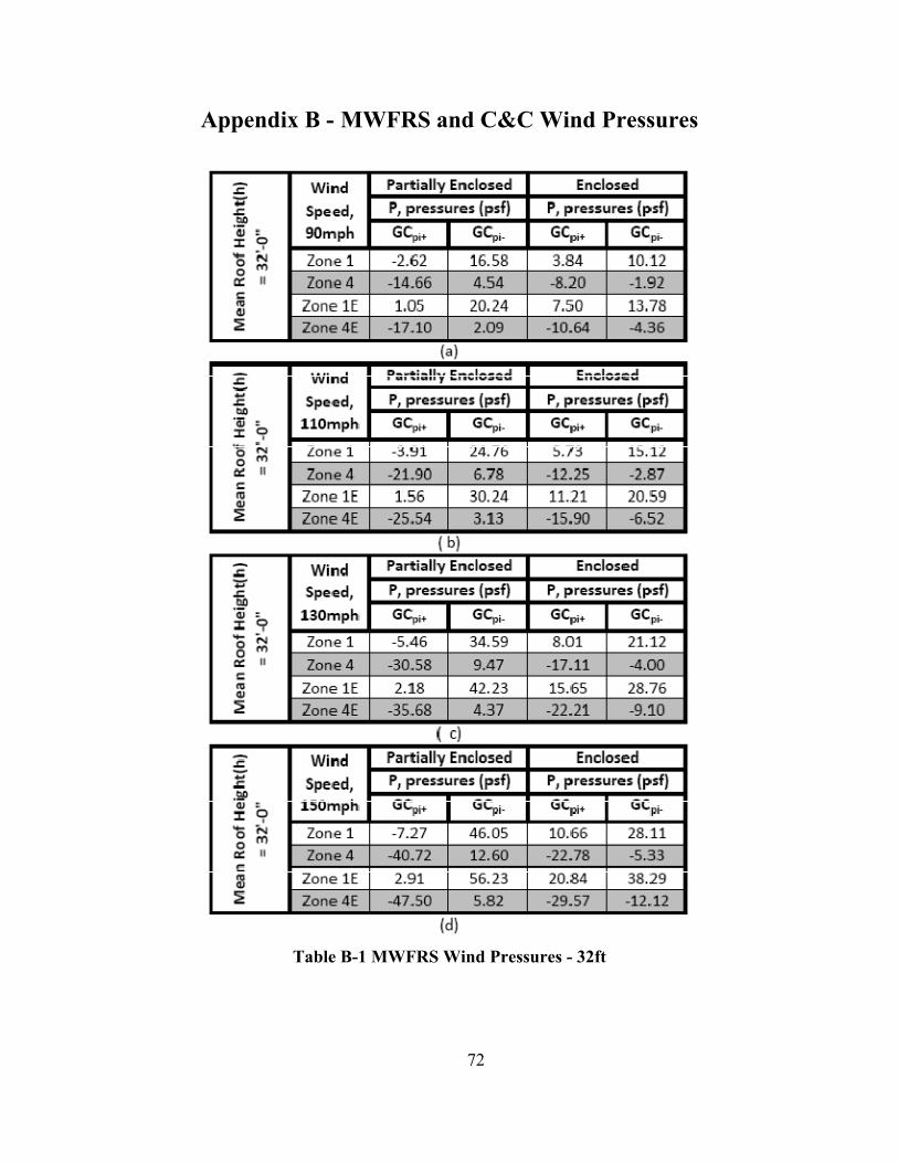
Appendix B - MWFRS and C&C Wind Pressures
Table B-1 MWFRS Wind Pressures - 32ft
72
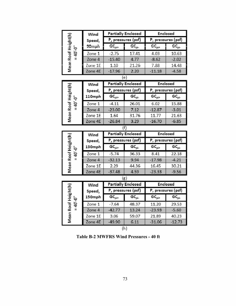
Table B-2 MWFRS Wind Pressures - 40 ft
73

Table B-3 C&C Wind Pressures
74

Appendix C - Load Combination Results
Table C-1 Solid Panels - 32 ft 75
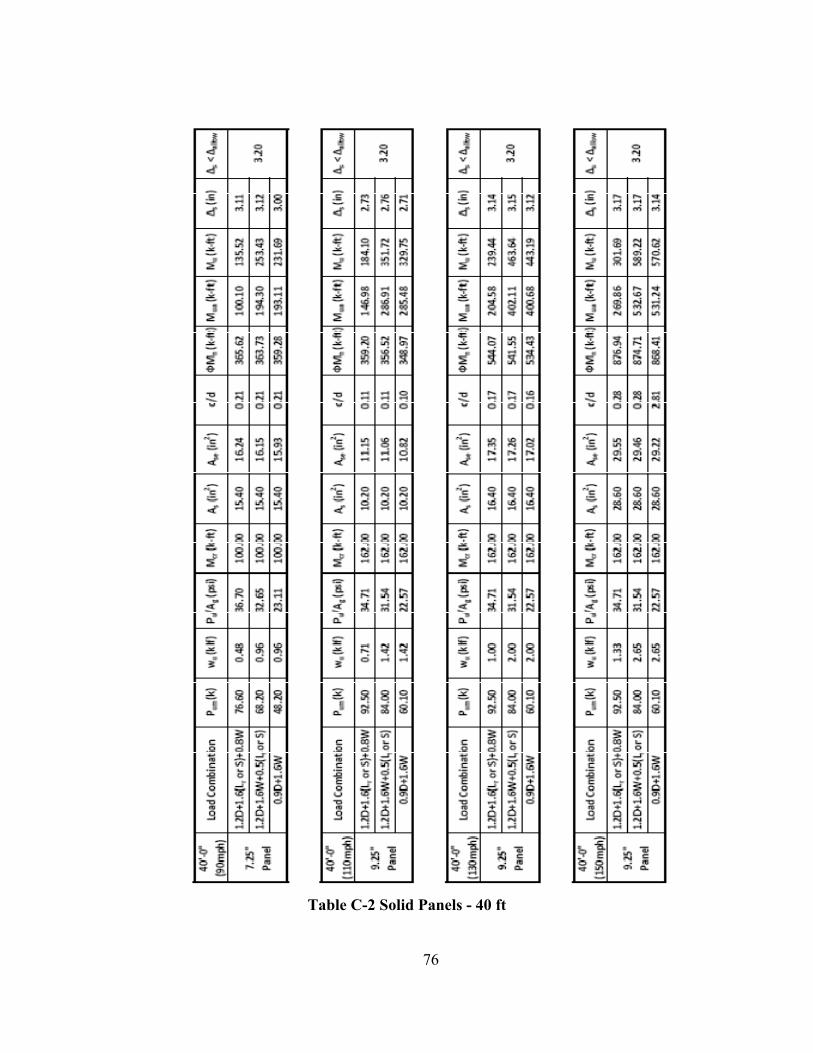
Table C-2 Solid Panels - 40 ft
76

Table C-3 Panel with Openings - 32 ft
77

Table C-4 Panel with Openings - 32 ft
78

Table C-5 Panel with Openings - 40 ft
79
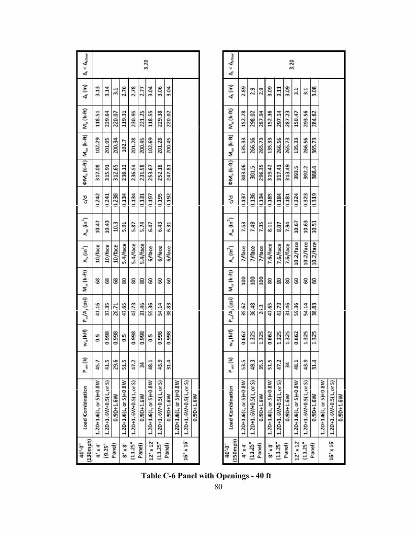
Table C-6 Panel with Openings - 40 ft
80

Appendix D - Reprint Image/Figure Permission
The images contained within this document are property of the author unless otherwise noted. Images provided by others are used by permission of the entities cited in this section. Permissions are listed alphabetically by party.
ACI 318-08 Building Code Requirements for Structural Concrete and Commentary
From: [email protected] To: Brian Bartels [email protected] Date: Wed, Mar 31, 2010 at 11:42 AM Subject:Re: ACI 318-08
Dear Brian Bartels, I hope this e-mail finds you well. Please accept this e-mail as permission to reprint the requested figures detailed in the attached request form in your Master's report. Please be sure to credit ACI, the 318-08, and its authors. Please feel free to contact me if you need further assistance. Have a great day, Daniela
ACI 551 Design Guide for Tilt-Up Concrete Panels
From: [email protected] To: [email protected] Date: Tue, Mar 16, 2010 at 6:22 AM Subject:Re: KSU Architectural Engg Masters Report --Brian Bartels
Brian, Please find attached the two figures you requested in Word format.
Thank you, Jeff
81

PCA Notes on ACI 318-08 Building Code Requirements for Structural Concrete From: Rabbat, Basile [email protected] To: Brian Bartels <[email protected]> cc: "Novak, Larry" <[email protected]> Date: Tue, Apr 6, 2010 at 10:00 AMsubject Subject:RE: PCA Notes on ACI 318-08
Brian,
This is to grant you permission to reproduce a part of Figure 7-1 from PCA’s publication Notes on ACI 318-08 Building Code Requirements for Structural Concrete. Usually, we request that you acknowledge the source of the figure. In this case, since it is only a small part of the figure, and essentially depicts basic equilibrium for flexural analysis, there is no need to acknowledge the source. Note, tilt-up walls are discussed in Part 21 of the subject publication.
Best wishes with your report,
Basile Rabbat
Design of Reinforced Concrete ACI 318-05 Code Edition, 7th Edition
82