analyze geometry of buildings using the autodesk® revit® api · analyze geometry of buildings...
TRANSCRIPT

Analyze Geometry of Buildings Using the Autodesk® Revit®
API Scott Conover – Autodesk
CP222-3
Learn tips and techniques to extract geometric and measurement data from Revit models using the Revit API. You will learn how Revit parameterizes 2D and 3D geometry of various building elements, including walls, floors, roofs and structural framing. You will learn techniques for measuring quantities related to the building construction, including areas, volumes, and material usage. You will also see how ray-tracing utilities can assist with analysis of the physical relationships between elements in the Revit model. Attendees should have basic knowledge of Revit Architecture, Structure, or MEP and a familiarity with the Revit API.
About the Speaker: Scott is a Software Development Manager for Autodesk, leading the effort to expand the Autodesk® Revit® API. For 11 years, he has used customization interfaces to parametric 3D CAD systems in order to automate repetitive tasks, extend the application user interface, and transfer data between the CAD application and different data formats. Since joining Autodesk, he has worked on the design, implementation, and testing of Revit APIs, including most recently on the design of the 2010 Revit Family, MEP, and Ribbon APIs. Scott holds a Master of Computer Systems Engineering degree from Northeastern University with a concentration on CAD/CAM/CAE. [email protected]

Analyze Geometry of Buildings Using the Autodesk® Revit® API
2
This course covers some tips and techniques to extract geometric and measurement data from Revit
models using the Revit API. You will learn how Revit parameterizes 2D and 3D geometry of various
building elements, including walls, floors, roofs and structural framing. You will learn techniques for
measuring quantities related to the building construction, including areas, volumes, and material usage.
You will also see how ray-tracing utilities can assist with analysis of the physical relationships between
elements in the Revit model.
Geometry extraction Before we discuss the details of what you get when you extract geometry from an element in Revit, let’s
discuss the geometry extraction process.
Geometry options
Geometry is typically extracted from the indexed property Element.Geometry. (Element.get_Geometry()
in C#) This property accepts an options class which you must supply. The options class customizes the
type of output you receive:
ComputeReferences – this flag sets Revit to make the GeometryObject.Reference property
active for each geometry object extracted. When this is false, the property will be null.
Remember that the default is false, you must turn this on or your reference will not be
accessible
IncludeNonVisibleObjects –this flag new to Revit 2010 sets Revit to also return geometry objects
which are not visible in a default view. Most of this non-visible geometry is construction and
conditional geometry that the user sees when editing the element (for example, the center
plane of a window family instance). So, typically you would set this to false (the default) as you
don’t want to include such information in your output. However, some of this conditionally
visible geometry represents real-world objects, and in certain situations, you should extract it.
One such example is the geometry of insulation surrounding ducts in Revit MEP.
DetailLevel – this sets the detail level for the extracted geometry. Note that the default for this
is “medium”.
View – this sets the view that governs the extracted geometry. Note that the detail level for this
view will be used in place of “DetailLevel” if a view is assigned (so you will need to change the
view’s detail level depending on your desired output). Set the view when you want to extract
view-specific geometry not normally visible in the default 3D view.
Contents of the extracted geometry The extracted geometry is returned to you as an Autodesk.Revit.Geometry.Element. You can look at the
geometry members of that element by iterating the .Objects property. Typically, the objects returned at
the top level of the extracted geometry will be one of:

Analyze Geometry of Buildings Using the Autodesk® Revit® API
3
Solid – a boundary representation made up of faces and edges
Curve – a bounded 3D curve
Instance – an instance of a geometric element, placed and positioned within the element
An instance offers the ability to read its geometry through the GetSymbolGeometry() and
GetInstanceGeometry() methods. These methods return another Autodesk.Revit.Geometry.Element
which can be parsed just like the first level return from get_Geometry():
GetSymbolGeometry() returns the geometry represented in the coordinate system of the
family. Use this, for example, when you want a picture of the “generic” table without regards
to the orientation and placement location within the project.
GetInstanceGeometry() returns the geometry represented in the coordinate system of the
project where the instance is placed. Use this, for example, when you want a picture of the
specific geometry of the instance in the project (for example, ensuring that tables are placed
parallel to the walls of the room).
There are also overloads for both methods that transform the geometry by any arbitrary
coordinate system.
In some cases, instances may be nested many levels deep. (For example, a baluster in a railing placed
in a document, or any other example of nested family instances). We’ll discuss transformations and
their relationship to instance geometry later in this course.
Other sources of geometry Geometry can also be obtained from a variety of other properties and methods:
LocationCurve – curve driven elements like walls and beams report their profile through this
interface
References of dimensions – the references contain information regarding the geometry they
point to
Structural AnalyticalModel – returns curves and faces representing the analytical model of
structural elements
FindReferencesByDirection() – discussed later in this course
Curve parameterization Curves in the Revit API can be described as mathematical functions of an input parameter “u”, where
the location of the curve at any given point in XYZ space is a function of “u”. In Revit, the parameter can
be represented in two ways:

Analyze Geometry of Buildings Using the Autodesk® Revit® API
4
A ‘normalized’ parameter. The start value of the parameter is 0.0, and the end value is 1.0. This
makes evaluation of the curve along its extents very easy, for example, the midpoint is at
parameter 0.5. This is the typical way of addressing curve locations.
A ‘raw’ parameter. The start and end value of the parameter can be any value. For a given
curve, the value of the minimum and maximum raw parameter can be obtained through
Curve.get_EndParameter(int) (C#) or Curve.EndParameter(int) (VB.NET). Raw parameters are
useful because their units are the same as the Revit default units (feet). So to obtain a location
5 feet along the curve from the start point, you can take the raw parameter at the start and add
5 to it. Raw parameters are also the only way to evaluate unbound and cyclic curves.
The methods Curve.ComputeNormalizedParameter() and Curve.ComputeRawParameter() automatically
scale between the two parameter types. The method Curve.IsInside() evaluates a raw parameter to see
if it lies within the bounds of the curve.
You can use the parameter to evaluate a variety of properties of the curve at any given location:
The XYZ location of the given curve. This is returned from Curve.Evaluate(). Either the raw or
normalized parameter can be supplied. If you are also calling ComputeDerivatives(), this is also
the .Origin property of the Transform returned by that method.
The first derivative/tangent vector of the given curve. This is the .BasisX property of the
Transform returned by Curve.ComputeDerivatives().
The second derivative/normal vector of the given curve. This is the .BasisY property of the
Transform returned by Curve.ComputeDerivatives().
The binormal vector of the given curve, defined as the cross-product of the tangent and normal
vector. This is the .BasisZ property of the Transform returned by Curve.ComputeDerivatives().
All of the vectors returned are non-normalized (but you can normalize any vector in the Revit API with
XYZ.Normalize()). Note that there will be no value set for the normal and binormal vector when the
curve is a straight line. You can calculate a normal vector to the straight line in a given plane using the
tangent vector.
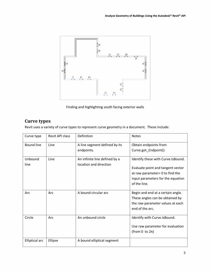
In this example we use the tangent vector to the wall location curve to find exterior walls that face
south.
Analyze Geometry of Buildings Using the Autodesk® Revit® API
5
Finding and highlighting south facing exterior walls
Curve types Revit uses a variety of curve types to represent curve geometry in a document. These include:
Curve type Revit API class Definition Notes
Bound line Line A line segment defined by its
endpoints.
Obtain endpoints from
Curve.get_Endpoint()
Unbound
line
Line An infinite line defined by a
location and direction
Identify these with Curve.IsBound.
Evaluate point and tangent vector
at raw parameter= 0 to find the
input parameters for the equation
of the line.
Arc Arc A bound circular arc Begin and end at a certain angle.
These angles can be obtained by
the raw parameter values at each
end of the arc.
Circle Arc An unbound circle Identify with Curve.IsBound.
Use raw parameter for evaluation
(from 0 to 2π)
Elliptical arc Ellipse A bound elliptical segment

Analyze Geometry of Buildings Using the Autodesk® Revit® API
6
Ellipse Ellipse An unbound ellipse Identify with Curve.IsBound. Use
raw parameter for evaluation
(from 0 to 2π)
NURBS NurbSpline A non-uniform rational B-spline Used for splines sketched in
various Revit tools, plus imported
geometry
Hermite HermiteSpline A spline interpolate between a
set of points
Used for tools like Curve by Points
and flexible ducts/pipes, plus
imported geometry
Mathematical representations of all of the Revit curve types can be found in Appendix A.
Curve analysis and processing There are several Curve members which are tools suitable for use in geometric analysis. In some cases,
these APIs do more than you might expect by a quick review of their names.
Intersect()
The Intersect method allows you compare two curves to find how they differ or how they are similar. It
can be used in the manner you might expect, to obtain the point or point(s) where two curves intersect
one another, but it can also be used to identify:
Collinear lines
Overlapping lines
Identical curves
Totally distinct curves with no intersections
The return value identifies these different results, and the output IntersectionSetResult contains
information on the intersection point(s).
Project()
The Project method projects a point onto the curve and returns information about the nearest point on
the curve, its parameter, and the distance from the projection point.
Tessellate()
This splits the curve into a series of linear segments, accurate within a default tolerance. For
Curve.Tessellate, the tolerance is slightly larger than 1/16”. This tolerance of approximation is the
tolerance used internally by Revit as adequate for display purposes.
Analyze Geometry of Buildings Using the Autodesk® Revit® API
7
Note that only lines may be split into output of only two tessellation points; non-linear curves will
always output more than two points even if the curve has an extremely large radius which might
mathematically equate to a straight line.
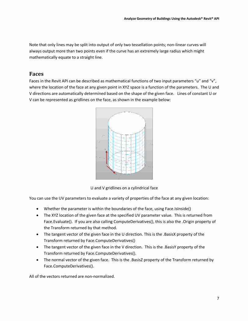
Faces Faces in the Revit API can be described as mathematical functions of two input parameters “u” and “v”,
where the location of the face at any given point in XYZ space is a function of the parameters. The U and
V directions are automatically determined based on the shape of the given face. Lines of constant U or
V can be represented as gridlines on the face, as shown in the example below:
U and V gridlines on a cylindrical face
You can use the UV parameters to evaluate a variety of properties of the face at any given location:
Whether the parameter is within the boundaries of the face, using Face.IsInside()
The XYZ location of the given face at the specified UV parameter value. This is returned from
Face.Evaluate(). If you are also calling ComputeDerivatives(), this is also the .Origin property of
the Transform returned by that method.
The tangent vector of the given face in the U direction. This is the .BasisX property of the
Transform returned by Face.ComputeDerivatives()
The tangent vector of the given face in the V direction. This is the .BasisY property of the
Transform returned by Face.ComputeDerivatives().
The normal vector of the given face. This is the .BasisZ property of the Transform returned by
Face.ComputeDerivatives().
All of the vectors returned are non-normalized.

Analyze Geometry of Buildings Using the Autodesk® Revit® API
8
Edges and face parameterization Edges are boundary curves for a given face.
Iterate the edges of a Face using the EdgeLoops property. Each loop represents one closed boundary
on the face. Edges are always parameterized from 0 to 1.
An edge is usually defined by computing intersection of two faces. But Revit doesn’t recompute this
intersection when it draws graphics. So the edge stores a list of points - end points for a straight edge
and a tessellated list for a curved edge. The points are parametric coordinates on the two faces. These
points are available through the TessellateOnFace() method.
Sections produce “cut edges”. These are artificial edges - not representing a part of the model-level
geometry, and thus do not provide a Reference.
Edge direction
Direction is normally clockwise on the first face (first representing an arbitrary face which Revit has
identified for a particular edge). But because two different faces meet at one particular edge, and the
edge has the same parametric direction regardless of which face you are concerned with, sometimes
you need to figure out the direction of the edge on a particular face.
The figure below illustrated how this works. For Face 0, the edges are all parameterized clockwise. For
Face 1, the edge shared with Face 0 is not re-parameterized; thus with respect to Face 1 the edge has a
reversed direction, and some edges intersect where both edges’ parameters are 0 (or 1).
Edge parameterization
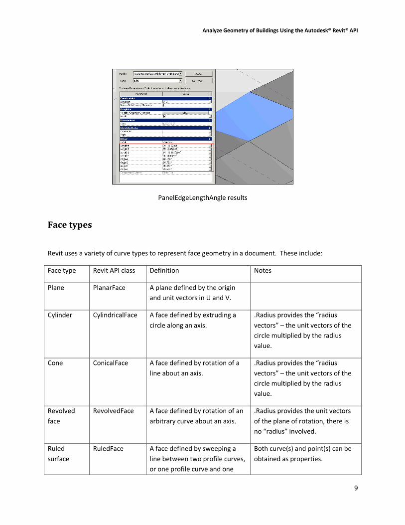
The API sample “PanelEdgeLengthAngle” shows how to recognize edges that are reversed for a given
face. It uses the tangent vector at the edge endpoints to calculate the angle between adjacent edges,
and detect whether or not to flip the tangent vector at each intersection to calculate the proper angle.
Analyze Geometry of Buildings Using the Autodesk® Revit® API
9
PanelEdgeLengthAngle results
Face types
Revit uses a variety of curve types to represent face geometry in a document. These include:
Face type Revit API class Definition Notes
Plane PlanarFace A plane defined by the origin
and unit vectors in U and V.
Cylinder CylindricalFace A face defined by extruding a
circle along an axis.
.Radius provides the “radius
vectors” – the unit vectors of the
circle multiplied by the radius
value.
Cone ConicalFace A face defined by rotation of a
line about an axis.
.Radius provides the “radius
vectors” – the unit vectors of the
circle multiplied by the radius
value.
Revolved
face
RevolvedFace A face defined by rotation of an
arbitrary curve about an axis.
.Radius provides the unit vectors
of the plane of rotation, there is
no “radius” involved.
Ruled
surface
RuledFace A face defined by sweeping a
line between two profile curves,
or one profile curve and one
Both curve(s) and point(s) can be
obtained as properties.

Analyze Geometry of Buildings Using the Autodesk® Revit® API
10
point.
Hermite
face
HermiteFace A face defined by Hermite
interpolation between points.
Mathematical representations of all of the Revit face types can be found in Appendix B.
Face analysis and processing There are several Face members which are tools suitable for use in geometric analysis.
Intersect()
The Intersect method computes the intersection between the face and a curve. It can be used in to
identify:
The intersection point(s) between the two objects
The edge nearest the intersection point, if there is an edge close to this location
Curves totally coincident with a face
Curves and faces which do not intersect
Project()
The Project method projects a point on the input face, and returns information on the projection point,
the distance to the face, and the nearest edge to the projection point.
Triangulate()
The Triangulate method obtains a triangular mesh approximating the face. Similar to Curve.Tessellate(),
this mesh’s points are accurate within the input tolerance used by Revit (slightly larger than 1/16”).
Coordinate Transformations Revit and the Revit API use coordinate transformations in a variety of ways. In most cases,
transformations are represented in the API as Transform objects. A transform object represents a
homogenous transformation combining elements of rotation, translation, and less commonly, scaling
and reflection:
𝐌 =
𝑟𝑥𝑥 𝑟𝑦𝑥 𝑟𝑧𝑥𝑟𝑥𝑦 𝑟𝑦𝑦 𝑟𝑧𝑦𝑟𝑥𝑧 𝑟𝑦𝑧 𝑟𝑧𝑧
𝑇𝑥𝑇𝑦𝑇𝑧
0 0 0 1

Analyze Geometry of Buildings Using the Autodesk® Revit® API
11
In this matrix, the 3 x 3 matrix represents the rotation applied via the transform, while the 1 x 3 matrix
represents the translation. Scaling and mirror properties, if applied, show up as multipliers on the
matrix members. Mathematically, a transformation of a point looks like this:
𝐏𝑡𝑟𝑎𝑛𝑠 = 𝐌 × 𝐏0 =
𝑟𝑥𝑥 𝑟𝑦𝑥 𝑟𝑧𝑥𝑟𝑥𝑦 𝑟𝑦𝑦 𝑟𝑧𝑦𝑟𝑥𝑧 𝑟𝑦𝑧 𝑟𝑧𝑧
𝑇𝑥𝑇𝑦𝑇𝑧
0 0 0 1
×
𝑃𝑥𝑃𝑦𝑃𝑧1
In the Transform class you have direct access to the members of the transformation matrix:
The properties BasisX, BasisY, and BasisZ are the unit vectors of the rotated coordinate system.
The Origin property is the translation vector.
Use the Transform.OfPoint() and Transform.OfVector() methods to apply the transformation to a given
input point or vector. You can also use the Transformed indexed properties (on Curve, Profile, and
Mesh) to transform geometry you extracted from Revit into an alternate coordinate system.
You obtain a transform from a variety of operations:
From the Instance class (the transformation applied to the instance)
From a Reference containing an Instance
From a Panel (curtain panel) element
From a 3D bounding box
From static properties on Transform (.Identity, .Reflection, .Rotation, .Translation)
By multiplying two Transforms together (Transform.Multiply())
By scaling a transform (and possibly its origin) (Transform.ScaleBasis() and
Transform.ScaleBasisAndOrigin())
By constructing one from scratch (Transform constructor)
Typically Transforms are right-handed coordinate systems, but mirror operations will produce left-
handed coordinate systems. Note that Revit sometimes produces left-handed coordinate systems via
flip operations on certain elements.
Transformation of Instances The Instance class stores geometry data in the SymbolGeometry property using a local coordinate
system. It also provides a Transform instance to convert the local coordinate system to a world
coordinate space. To get the same geometry data as the Revit application from the Instance class, use
the transform property to convert each geometry object retrieved from the SymbolGeometry property.
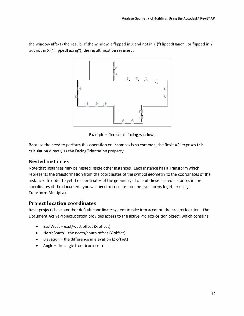
In this example, we use the transform of the Instance stored in a window FamilyInstance to find south
facing windows. The Y direction of the transform is the facing direction; however, the flipped status of
Analyze Geometry of Buildings Using the Autodesk® Revit® API
12
the window affects the result. If the window is flipped in X and not in Y (“FlippedHand”), or flipped in Y
but not in X (“FlippedFacing”), the result must be reversed.
Example – find south facing windows
Because the need to perform this operation on instances is so common, the Revit API exposes this
calculation directly as the FacingOrientation property.
Nested instances Note that instances may be nested inside other instances. Each instance has a Transform which
represents the transformation from the coordinates of the symbol geometry to the coordinates of the
instance. In order to get the coordinates of the geometry of one of these nested instances in the
coordinates of the document, you will need to concatenate the transforms together using
Transform.Multiply().
Project location coordinates Revit projects have another default coordinate system to take into account: the project location. The
Document.ActiveProjectLocation provides access to the active ProjectPosition object, which contains:
EastWest – east/west offset (X offset)
NorthSouth – the north/south offset (Y offset)
Elevation – the difference in elevation (Z offset)
Angle – the angle from true north
Analyze Geometry of Buildings Using the Autodesk® Revit® API
13
You can use these properties to construct a transform between the default Revit coordinates and the
actual coordinates in the project:
//Obtain a rotation transform for the angle about true north
Transform rotationTransform = Transform.get_Rotation(
XYZ.Zero, XYZ.BasisZ, pna );
//Obtain a translation vector for the offsets
XYZ translationVector = new XYZ(projectPosition.EastWest,
projectPosition.NorthSouth, projectPosition.Elevation);
Transform translationTransform =
Transform.get_Translation(translationVector);
//Combine the transforms into one.
Transform finalTransform =
translationTransform.Multiply(rotationTransform);
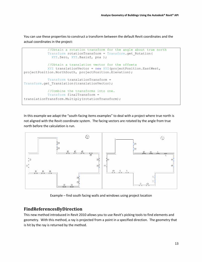
In this example we adapt the “south-facing items examples” to deal with a project where true north is
not aligned with the Revit coordinate system. The facing vectors are rotated by the angle from true
north before the calculation is run.
Example – find south facing walls and windows using project location
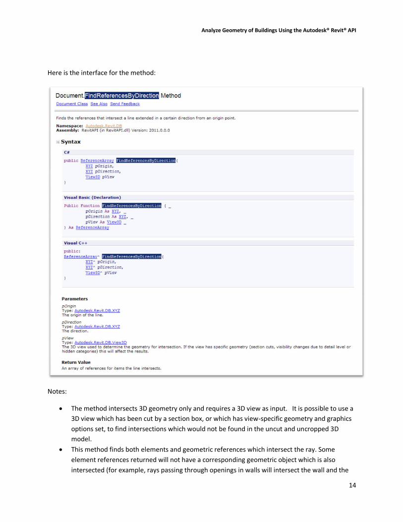
FindReferencesByDirection This new method introduced in Revit 2010 allows you to use Revit’s picking tools to find elements and
geometry. With this method, a ray is projected from a point in a specified direction. The geometry that
is hit by the ray is returned by the method.
Analyze Geometry of Buildings Using the Autodesk® Revit® API
14
Here is the interface for the method:
Notes:
The method intersects 3D geometry only and requires a 3D view as input. It is possible to use a
3D view which has been cut by a section box, or which has view-specific geometry and graphics
options set, to find intersections which would not be found in the uncut and uncropped 3D
model.
This method finds both elements and geometric references which intersect the ray. Some
element references returned will not have a corresponding geometric object which is also
intersected (for example, rays passing through openings in walls will intersect the wall and the

Analyze Geometry of Buildings Using the Autodesk® Revit® API
15
opening element). If you are interested only in true physical intersections you should discard all
references whose GeometryObject is of type Element, leaving behind only intersections with
faces.
References will be found and returned only for elements that are in front of the ray. (This is a
contradiction to the note in the 2010 documentation, which states that negative results are
possible; they are not).
This method will not return intersections in linked files.
This method will not return intersections with elements which are not in the active design
option.
Find elements near elements One major use for this tool is to find elements in close proximity to other elements. This allows you to
use the tool as your application’s “eyes” and determine relationships between elements which don’t
have a built-in relationship already.
In this example, we use the ray-tracing capability to find columns embedded in walls. As columns and
walls don’t maintain a relationship directly, this utility allows us to find potential candidates by tracing
rays just outside the extents of the wall, and looking for intersections with columns. The
implementation covers flat walls (where only two rays, one for either side, are necessary), as well as
curved walls, where the rays are traced tangent to the walls at incremental distances, and only matches
in close proximity are accepted.
Example: find columns embedded in walls
Measure distances The results of the FindReferencesByDirection are an array of Reference objects intersected by the ray.
When the References are obtained from this method, the References’ ProximityParameter will be set.

Analyze Geometry of Buildings Using the Autodesk® Revit® API
16
This is the distance between the origin of the ray and the intersection point. You can use this distance
to exclude items too far from the origin for a particular geometric analysis. You can also use this
distance to take on some interesting problems involving analyzing the in place geometry of the model.
In this example, we measure the vertical distance from a skylight to a preselected floor. Yes, this could
be obtained through geometric tools as well (Face.Project()), but with the ray-tracing tool, we don’t
have to examine the floor to find its top face(s), nor deal with sloped slabs or other problematic details.
We just look at all the intersections with the floor, pick the closest one, and thus have found our
distance and intersection point.
Example: measure with FindReferencesByDirection()
Ray bouncing/analysis The references returned by FindReferencesByDirection also include the intersection point on the
geometry. Knowing the intersection point on the face, the face’s material, and the ray direction allows
you analyze reflection and refraction within the building.

Analyze Geometry of Buildings Using the Autodesk® Revit® API
17
Example: Rays bouncing off intersected faces
Material quantity extraction One common analytical requirement is to extract material quantities of elements in the document.
Revit 2010 introduced methods to directly obtain the material volumes and areas computed by Revit for
material takeoff schedules:
Element.Materials – obtains a list of materials within an element
Element.GetMaterialVolume() – obtains the volume of a particular material in an element
Element.GetMaterialArea() – obtains the area of a particular material in an element
The methods apply to categories of elements where Category.HasMaterialQuantities property is true. In
practice, this is limited to elements that use compound structure, like walls, roofs, floors, ceilings, a few
other basic 3D elements like stairs, plus 3D families where materials can be assigned to geometry of the
family, like windows, doors, columns, MEP equipment and fixtures, and generic model families. Note
that within these categories there are further restrictions about how material quantities can be
extracted. For example, curtain walls and curtain roofs will not report any material quantities
themselves; the materials used by these constructs can be extracted from the individual panel elements
that make up the curtain system.
Note that the volumes and areas computed by Revit may be approximate in some cases. For example,
for individual layers within a wall, minor discrepancies might appear between the volumes visible in the
model and those shown in the material takeoff schedule. These discrepancies tend to occur when you
use the wall sweep tool to add a sweep or a reveal to a wall, or under certain join conditions.
Analyze Geometry of Buildings Using the Autodesk® Revit® API
18
These methods allow you to extract the material quantities for an as-modeled Revit project. But what if
you need to extract gross material quantities of layered elements like walls, floors, and roofs, where the
quantities are extracted before they are cut or modified by other elements?
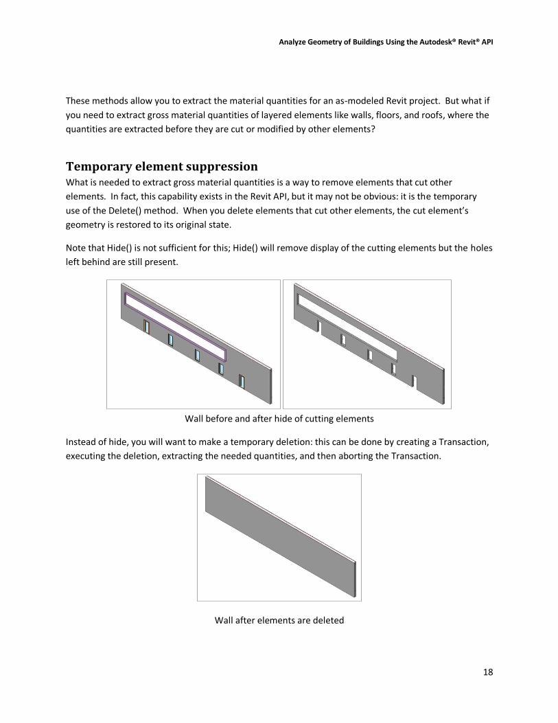
Temporary element suppression What is needed to extract gross material quantities is a way to remove elements that cut other
elements. In fact, this capability exists in the Revit API, but it may not be obvious: it is the temporary
use of the Delete() method. When you delete elements that cut other elements, the cut element’s
geometry is restored to its original state.
Note that Hide() is not sufficient for this; Hide() will remove display of the cutting elements but the holes
left behind are still present.
Wall before and after hide of cutting elements
Instead of hide, you will want to make a temporary deletion: this can be done by creating a Transaction,
executing the deletion, extracting the needed quantities, and then aborting the Transaction.
Wall after elements are deleted
Analyze Geometry of Buildings Using the Autodesk® Revit® API
19
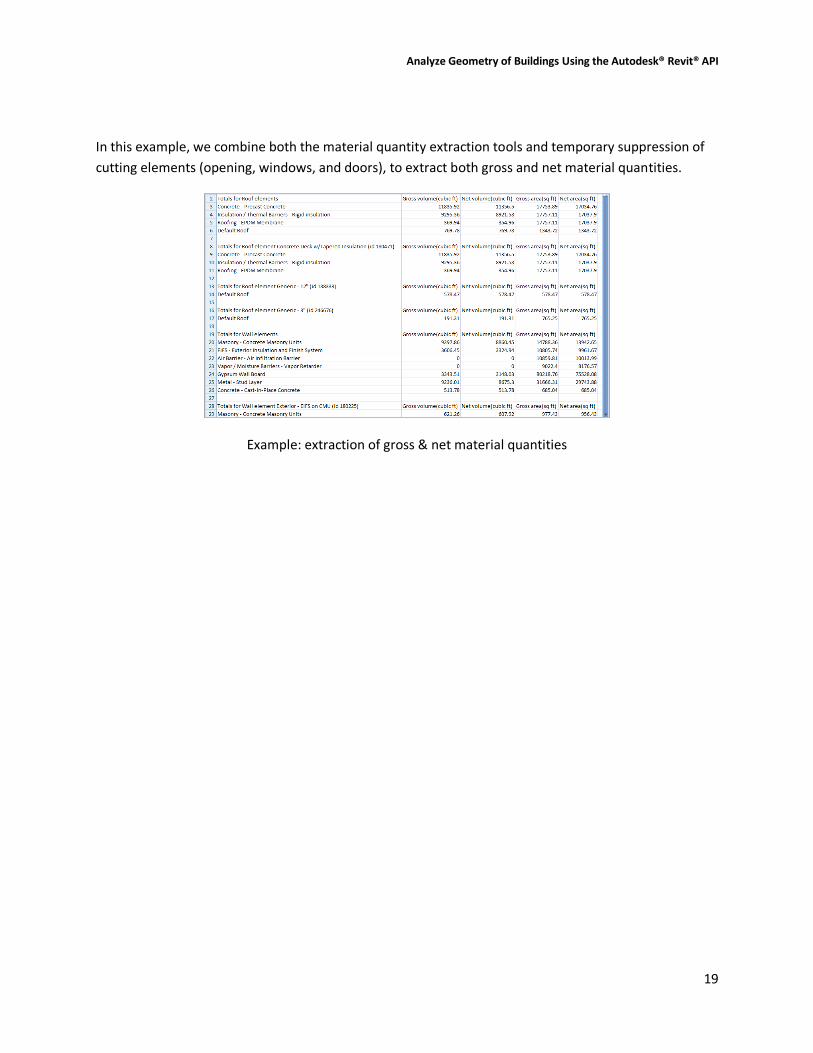
In this example, we combine both the material quantity extraction tools and temporary suppression of
cutting elements (opening, windows, and doors), to extract both gross and net material quantities.
Example: extraction of gross & net material quantities
Analyze Geometry of Buildings Using the Autodesk® Revit® API
20
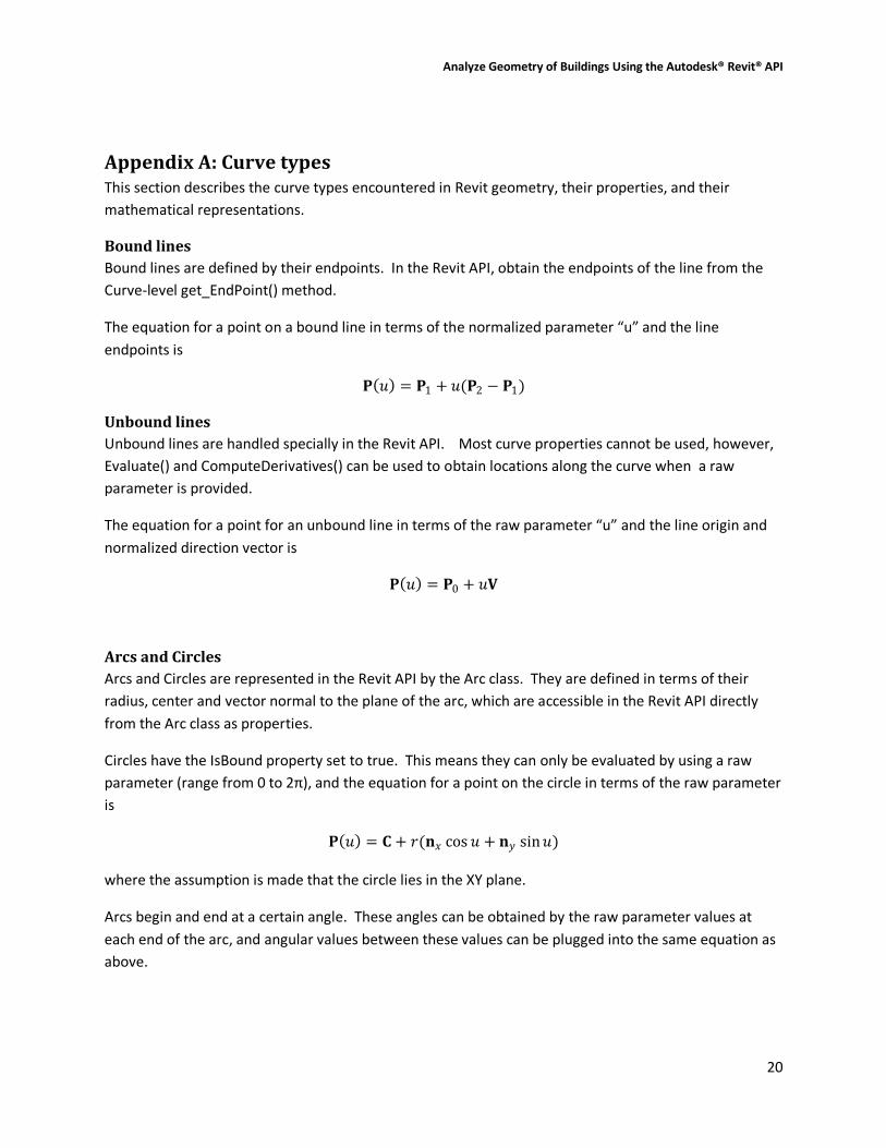
Appendix A: Curve types This section describes the curve types encountered in Revit geometry, their properties, and their
mathematical representations.
Bound lines
Bound lines are defined by their endpoints. In the Revit API, obtain the endpoints of the line from the
Curve-level get_EndPoint() method.
The equation for a point on a bound line in terms of the normalized parameter “u” and the line
endpoints is
𝐏 𝑢 = 𝐏1 + 𝑢(𝐏2 − 𝐏1)
Unbound lines
Unbound lines are handled specially in the Revit API. Most curve properties cannot be used, however,
Evaluate() and ComputeDerivatives() can be used to obtain locations along the curve when a raw
parameter is provided.
The equation for a point for an unbound line in terms of the raw parameter “u” and the line origin and
normalized direction vector is
𝐏 𝑢 = 𝐏0 + 𝑢𝐕
Arcs and Circles
Arcs and Circles are represented in the Revit API by the Arc class. They are defined in terms of their
radius, center and vector normal to the plane of the arc, which are accessible in the Revit API directly
from the Arc class as properties.
Circles have the IsBound property set to true. This means they can only be evaluated by using a raw
parameter (range from 0 to 2π), and the equation for a point on the circle in terms of the raw parameter
is
𝐏 𝑢 = 𝐂 + 𝑟(𝐧𝑥 cos 𝑢 + 𝐧𝑦 sin𝑢)
where the assumption is made that the circle lies in the XY plane.
Arcs begin and end at a certain angle. These angles can be obtained by the raw parameter values at
each end of the arc, and angular values between these values can be plugged into the same equation as
above.
Analyze Geometry of Buildings Using the Autodesk® Revit® API
21
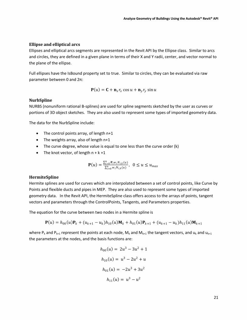
Ellipse and elliptical arcs
Ellipses and elliptical arcs segments are represented in the Revit API by the Ellipse class. Similar to arcs
and circles, they are defined in a given plane in terms of their X and Y radii, center, and vector normal to
the plane of the ellipse.
Full ellipses have the IsBound property set to true. Similar to circles, they can be evaluated via raw
parameter between 0 and 2π:
𝐏 𝑢 = 𝐂 + 𝐧𝑥𝑟𝑥 cos 𝑢 + 𝐧𝑦𝑟𝑦 sin𝑢
NurbSpline
NURBS (nonuniform rational B-splines) are used for spline segments sketched by the user as curves or
portions of 3D object sketches. They are also used to represent some types of imported geometry data.
The data for the NurbSpline include:
The control points array, of length n+1
The weights array, also of length n+1
The curve degree, whose value is equal to one less than the curve order (k)
The knot vector, of length n + k +1
𝐏 𝑢 = 𝐏𝑖𝑤 𝑖𝑁𝑖,𝑘(𝑢)𝑛
𝑖=0
𝑤 𝑖𝑁𝑖,𝑘(𝑢)𝑛𝑖=0
, 0 ≤ 𝑢 ≤ 𝑢𝑚𝑎𝑥
HermiteSpline
Hermite splines are used for curves which are interpolated between a set of control points, like Curve by
Points and flexible ducts and pipes in MEP. They are also used to represent some types of imported
geometry data. In the Revit API, the HermiteSpline class offers access to the arrays of points, tangent
vectors and parameters through the ControlPoints, Tangents, and Parameters properties.
The equation for the curve between two nodes in a Hermite spline is
𝐏 𝑢 = ℎ00 𝑢 𝐏𝑘 + (𝑢𝑘+1 − 𝑢𝑘)ℎ10 𝑢 𝐌𝑘 + ℎ01 𝑢 𝐏𝑘+1 + (𝑢𝑘+1 − 𝑢𝑘 )ℎ11 𝑢 𝐌𝑘+1
where Pk and Pk+1 represent the points at each node, Mk and Mk+1 the tangent vectors, and uk and uk+1
the parameters at the nodes, and the basis functions are:
ℎ00 𝑢 = 2𝑢3 − 3𝑢2 + 1
ℎ10 𝑢 = 𝑢3 − 2𝑢2 + 𝑢
ℎ01 𝑢 = −2𝑢3 + 3𝑢2
ℎ11 𝑢 = 𝑢3 − 𝑢2
Analyze Geometry of Buildings Using the Autodesk® Revit® API
22
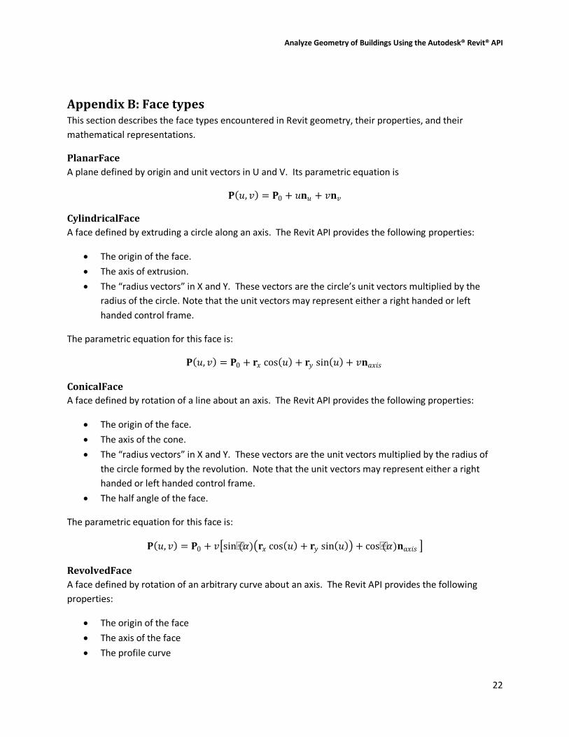
Appendix B: Face types This section describes the face types encountered in Revit geometry, their properties, and their
mathematical representations.
PlanarFace
A plane defined by origin and unit vectors in U and V. Its parametric equation is
𝐏 𝑢, 𝑣 = 𝐏0 + 𝑢𝐧𝑢 + 𝑣𝐧𝑣
CylindricalFace
A face defined by extruding a circle along an axis. The Revit API provides the following properties:
The origin of the face.
The axis of extrusion.
The “radius vectors” in X and Y. These vectors are the circle’s unit vectors multiplied by the
radius of the circle. Note that the unit vectors may represent either a right handed or left
handed control frame.
The parametric equation for this face is:
𝐏 𝑢, 𝑣 = 𝐏0 + 𝐫𝑥 cos 𝑢 + 𝐫𝑦 sin 𝑢 + 𝑣𝐧𝑎𝑥𝑖𝑠
ConicalFace
A face defined by rotation of a line about an axis. The Revit API provides the following properties:
The origin of the face.
The axis of the cone.
The “radius vectors” in X and Y. These vectors are the unit vectors multiplied by the radius of
the circle formed by the revolution. Note that the unit vectors may represent either a right
handed or left handed control frame.
The half angle of the face.
The parametric equation for this face is:
𝐏 𝑢, 𝑣 = 𝐏0 + 𝑣 sin(𝛼) 𝐫𝑥 cos 𝑢 + 𝐫𝑦 sin 𝑢 + cos(𝛼)𝐧𝑎𝑥𝑖𝑠
RevolvedFace
A face defined by rotation of an arbitrary curve about an axis. The Revit API provides the following
properties:
The origin of the face
The axis of the face
The profile curve
Analyze Geometry of Buildings Using the Autodesk® Revit® API
23
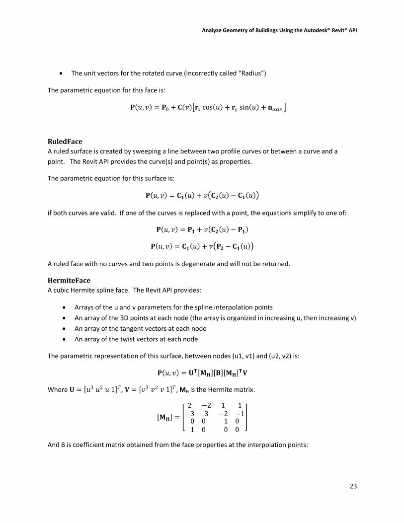
The unit vectors for the rotated curve (incorrectly called “Radius”)
The parametric equation for this face is:
𝐏 𝑢, 𝑣 = 𝐏0 + 𝐂(𝑣) 𝐫𝑥 cos 𝑢 + 𝐫𝑦 sin 𝑢 + 𝐧𝑎𝑥𝑖𝑠
RuledFace
A ruled surface is created by sweeping a line between two profile curves or between a curve and a
point. The Revit API provides the curve(s) and point(s) as properties.
The parametric equation for this surface is:
𝐏 𝑢, 𝑣 = 𝐂𝟏 𝑢 + 𝑣 𝐂𝟐 𝑢 − 𝐂𝟏 𝑢
if both curves are valid. If one of the curves is replaced with a point, the equations simplify to one of:
𝐏 𝑢, 𝑣 = 𝐏𝟏 + 𝑣 𝐂𝟐 𝑢 − 𝐏𝟏
𝐏 𝑢, 𝑣 = 𝐂𝟏 𝑢 + 𝑣 𝐏𝟐 − 𝐂𝟏 𝑢
A ruled face with no curves and two points is degenerate and will not be returned.
HermiteFace
A cubic Hermite spline face. The Revit API provides:
Arrays of the u and v parameters for the spline interpolation points
An array of the 3D points at each node (the array is organized in increasing u, then increasing v)
An array of the tangent vectors at each node
An array of the twist vectors at each node
The parametric representation of this surface, between nodes (u1, v1) and (u2, v2) is:
𝐏 𝑢, 𝑣 = 𝐔𝐓 𝐌𝐇 𝐁 𝐌𝐇 𝐓𝐕
Where 𝐔 = 𝑢3 𝑢2 𝑢 1 𝑇, 𝐕 = 𝑣3 𝑣2 𝑣 1 𝑇, MH is the Hermite matrix:
𝐌𝐇 =
2 −2−3 3
1 1−2 −1
0 01 0
1 00 0
And B is coefficient matrix obtained from the face properties at the interpolation points:

Analyze Geometry of Buildings Using the Autodesk® Revit® API
24
𝐁 =
𝐏𝑢1𝑣1𝐏𝑢1𝑣2
𝐏𝑢2𝑣1𝐏𝑢2𝑣2
𝐏′𝑣(𝑢1𝑣1) 𝐏′𝑣(𝑢1𝑣2)
𝐏′𝑣(𝑢2𝑣1) 𝐏′𝑣(𝑢2𝑣2)
𝐏′𝑢(𝑢1𝑣1) 𝐏′𝑢(𝑢1𝑣2)
𝐏′𝑢(𝑢2𝑣1) 𝐏′𝑢(𝑢2𝑣2)
𝐏′𝑢𝑣 (𝑢1𝑣1) 𝐏′𝑢𝑣 (𝑢1𝑣2)
𝐏′𝑢𝑣 (𝑢2𝑣1) 𝐏′𝑢𝑣 (𝑢2𝑣2)