and/or property damage! retain instructions for future
TRANSCRIPT
E53236MH45468
Operating Instructions & Parts Manual 2RB67
Please read and save these instructions. Read carefully before attempting to assemble, install, operate or maintain the productdescribed. Protect yourself and others by observing all safety information. Failure to comply with instructions could result in personal injuryand/or property damage! Retain instructions for future reference.
Form 5S5541 ®
ENGLISH
Printed in U.S.A.046321006/268/VCPVP
General or UL 705Description Model No.’s
Optional Accessories
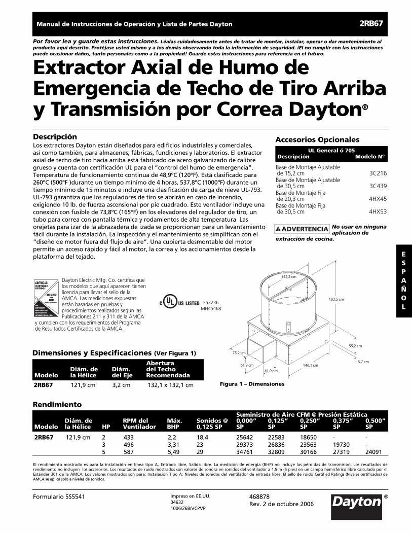
2RB67 48” 11⁄4“ 52 x 52”
RecommendedProp. Shaft Roof
Model Dia. Dia. Opening
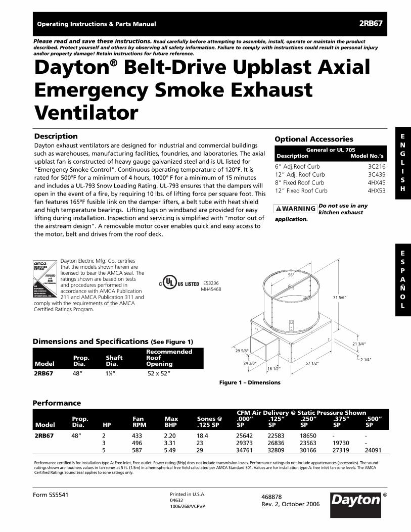
Dimensions and Specifications (See Figure 1)
468878Rev. 2, October 2006
6” Adj.Roof Curb 3C21612” Adj. Roof Curb 3C4398” Fixed Roof Curb 4HX4512” Fixed Roof Curb 4HX53
Do not use in anykitchen exhaust
application.
DescriptionDayton exhaust ventilators are designed for industrial and commercial buildingssuch as warehouses, manufacturing facilities, foundries, and laboratories. The axialupblast fan is constructed of heavy gauge galvanized steel and is UL listed for"Emergency Smoke Control". Continuous operating temperature of 120ºF. It israted for 500ºF for a minimum of 4 hours, 1000º F for a minimum of 15 minutesand includes a UL-793 Snow Loading Rating. UL-793 ensures that the dampers willopen in the event of a fire, by requiring 10 lbs. of lifting force per square foot. Thisfan features 165ºF fusible link on the damper lifters, a belt tube with heat shieldand high temperature bearings. Lifting lugs on windband are provided for easylifting during installation. Inspection and servicing is simplified with "motor out ofthe airstream design". A removable motor cover enables quick and easy access tothe motor, belt and drives from the roof deck.
ESPAÑOL
57 1/2"
29 5/8"
24 3/8"16 1/2"
56"
71 5/6"
2 1/4"
21 3/4"
Figure 1 – Dimensions
CFM Air Delivery @ Static Pressure ShownProp. Fan Max Sones @ .000” .125” .250” .375” .500”
Model Dia. HP RPM BHP .125 SP SP SP SP SP SP
Performance
2RB67 48” 2 433 2.20 18.4 25642 22583 18650 - -3 496 3.31 23 29373 26836 23563 19730 -5 587 5.49 29 34761 32809 30166 27319 24091
Performance certified is for installation type A: Free inlet, Free outlet. Power rating (BHp) does not include transmission losses. Performance ratings do not include appurtenances (accessories). The soundratings shown are loudness values in fan sones at 5 ft. (1.5m) in a hemispherical free field calculated per AMCA Standard 301. Values are for installation type A: free inlet fan sone levels. The AMCACertified Ratings Sound Seal applies to sone ratings only.
Dayton® Belt-Drive Upblast AxialEmergency Smoke ExhaustVentilator
Dayton Electric Mfg. Co. certifiesthat the models shown herein arelicensed to bear the AMCA seal. Theratings shown are based on testsand procedures performed inaccordance with AMCA Publication211 and AMCA Publication 311 and
comply with the requirements of the AMCACertified Ratings Program.
R
®
AIR
MOVEMENT
AND CONTROL
ASSOCIATION
INTERNATIONAL, INC.
AIRPERFORMANCE
SOUNDand
Unpacking1. Inspect for any damage that may
have occurred during transit.
2. Shipping damage claim must be filedwith carrier.
3. Check all bolts, screws, set-screws, etc.for looseness that may have occurredduring transit. Retighten as required.Rotate propeller by hand to be sure itturns freely.
Do not raise ventilatorby its windband; use
lifting lugs provided.
General Safety InformationWhen Installing or Servicingthe Fan
Do not depend on anyswitch as the sole
means of disconnecting power wheninstalling or servicing the fan. Alwaysdisconnect, lock and tag power sourcebefore installing or servicing. Failure todisconnect power source can result infire, shock or serious injury. Motor willrestart without warning after thermalprotector trips. Do not touch operatingmotor, it may be hot enough to causeinjury.
Do not place any bodyparts or objects in fan,
motor openings or drives while motoris connected to power source.
Do not use thisequipment in explosive
atmospheres!
Extreme care must betaken when working
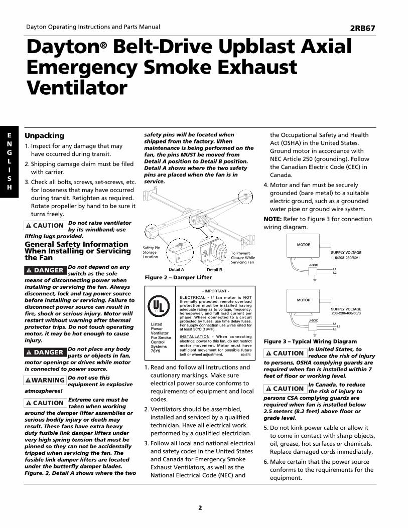
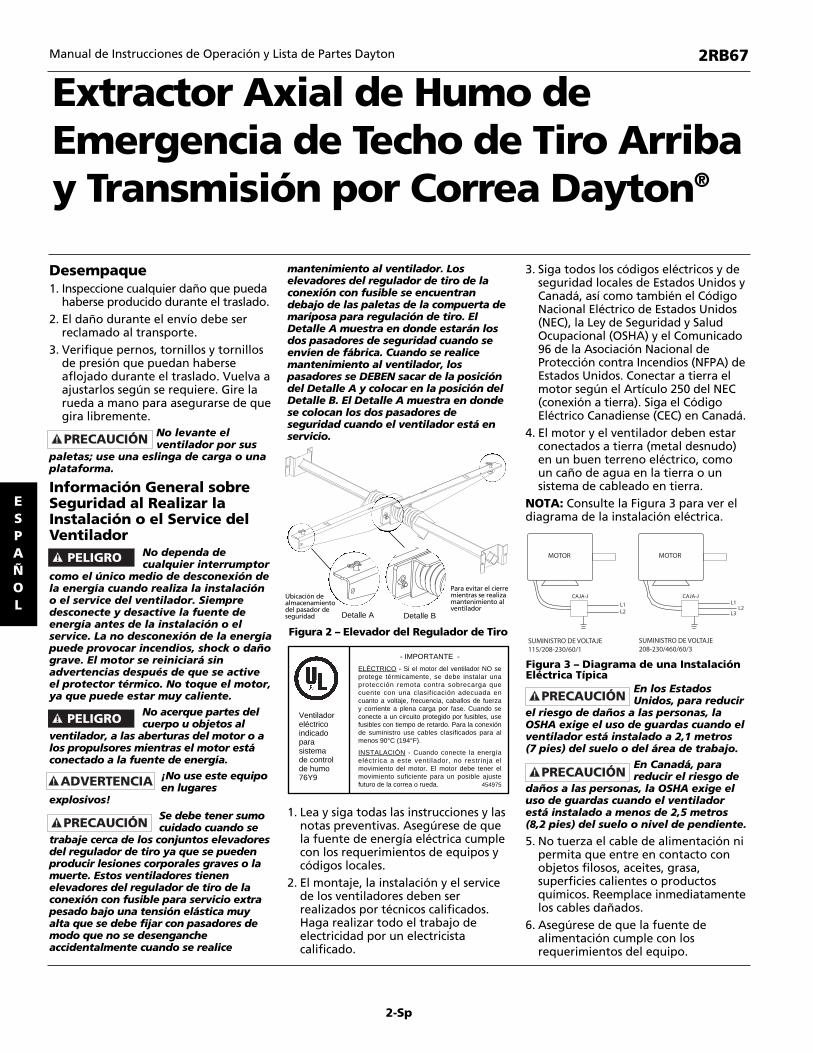
around the damper lifter assemblies orserious bodily injury or death mayresult. These fans have extra heavyduty fusible link damper lifters undervery high spring tension that must bepinned so they can not be accidentallytripped when servicing the fan. Thefusible link damper lifters are locatedunder the butterfly damper blades.Figure. 2, Detail A shows where the two
safety pins will be located whenshipped from the factory. Whenmaintenance is being performed on thefan, the pins MUST be moved fromDetail A position to Detail B position.Detail A shows where the two safetypins are placed when the fan is inservice.
1. Read and follow all instructions andcautionary markings. Make sureelectrical power source conforms torequirements of equipment and localcodes.
2. Ventilators should be assembled,installed and serviced by a qualifiedtechnician. Have all electrical workperformed by a qualified electrician.
3. Follow all local and national electricaland safety codes in the United Statesand Canada for Emergency SmokeExhaust Ventilators, as well as theNational Electrical Code (NEC) and
the Occupational Safety and HealthAct (OSHA) in the United States.Ground motor in accordance withNEC Article 250 (grounding). Followthe Canadian Electric Code (CEC) inCanada.
4. Motor and fan must be securelygrounded (bare metal) to a suitableelectric ground, such as a groundedwater pipe or ground wire system.
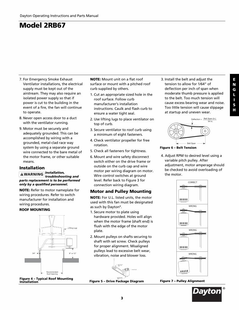
NOTE: Refer to Figure 3 for connectionwiring diagram.
In United States, toreduce the risk of injury
to persons, OSHA complying guards arerequired when fan is installed within 7feet of floor or working level.
In Canada, to reducethe risk of injury to
persons CSA complying guards arerequired when fan is installed below2.5 meters (8.2 feet) above floor orgrade level.
5. Do not kink power cable or allow itto come in contact with sharp objects,oil, grease, hot surfaces or chemicals.Replace damaged cords immediately.
6. Make certain that the power sourceconforms to the requirements for theequipment.
Dayton Operating Instructions and Parts Manual
Dayton® Belt-Drive Upblast AxialEmergency Smoke ExhaustVentilator
ENGLISH
2RB67
MOTOR
L1
115/208-230/60/1
208-230/460/60/3
MOTOR
J-BOX
J-BOX
SUPPLY VOLTAGE
SUPPLY VOLTAGE
L2
L1L2
L3
Figure 3 – Typical Wiring Diagram
- IMPORTANT -
ELECTRICAL - If fan motor is NOTthermally protected, remote overloadprotection must be installed havingadequate rating as to voltage, frequency,horsepower, and full load current perphase. Where connected to a circuitprotected by fuses, use time delay fuses.For supply connection use wires rated forat least 90ºC (194ºF).
INSTALLATION - When connectingelectrical power to this fan, do not restrictmotor movement. Motor must havesufficient movement for possible futurebelt or wheel adjustment. 454975
ListedPowerVentilatorFor SmokeControlSystems76Y9
Detail BDetail A
Safety PinStorageLocation
To PreventClosure WhileServicing Fan
Figure 2 – Damper Lifter
2
7. For Emergency Smoke ExhaustVentilator installations, the electricalsupply must be kept out of theairstream. They may also require anisolated power supply so that ifpower is cut to the building in theevent of a fire, the fan will continueto operate.
8. Never open access door to a ductwith the ventilator running.
9. Motor must be securely andadequately grounded. This can beaccomplished by wiring with agrounded, metal-clad race waysystem by using a separate groundwire connected to the bare metal ofthe motor frame, or other suitablemeans.
InstallationInstallation,troubleshooting and
parts replacement is to be performedonly by a qualified personnel.
NOTE: Refer to motor nameplate forwiring procedures. Refer to switchmanufacturer for installation andwiring procedures.
ROOF MOUNTING
NOTE: Mount unit on a flat roofsurface or mount with a pitched roofcurb supplied by others.
1. Cut an appropriate sized hole in theroof surface. Follow curbmanufacturer’s installationinstructions. Caulk and flash curb toensure a water tight seal.
2. Use lifting lugs to place ventilator ontop of curb.
3. Secure ventilator to roof curb usinga minimum of eight fasteners.
4. Check ventilator propeller for freerotation.
5. Check all fasteners for tightness.
6. Mount and wire safety disconnectswitch either on the drive frame oroutside on the curb cap and wiremotor per wiring diagram on motor.Wire control switches at groundlevel. Refer back to Figure 3 forconnection wiring diagram.
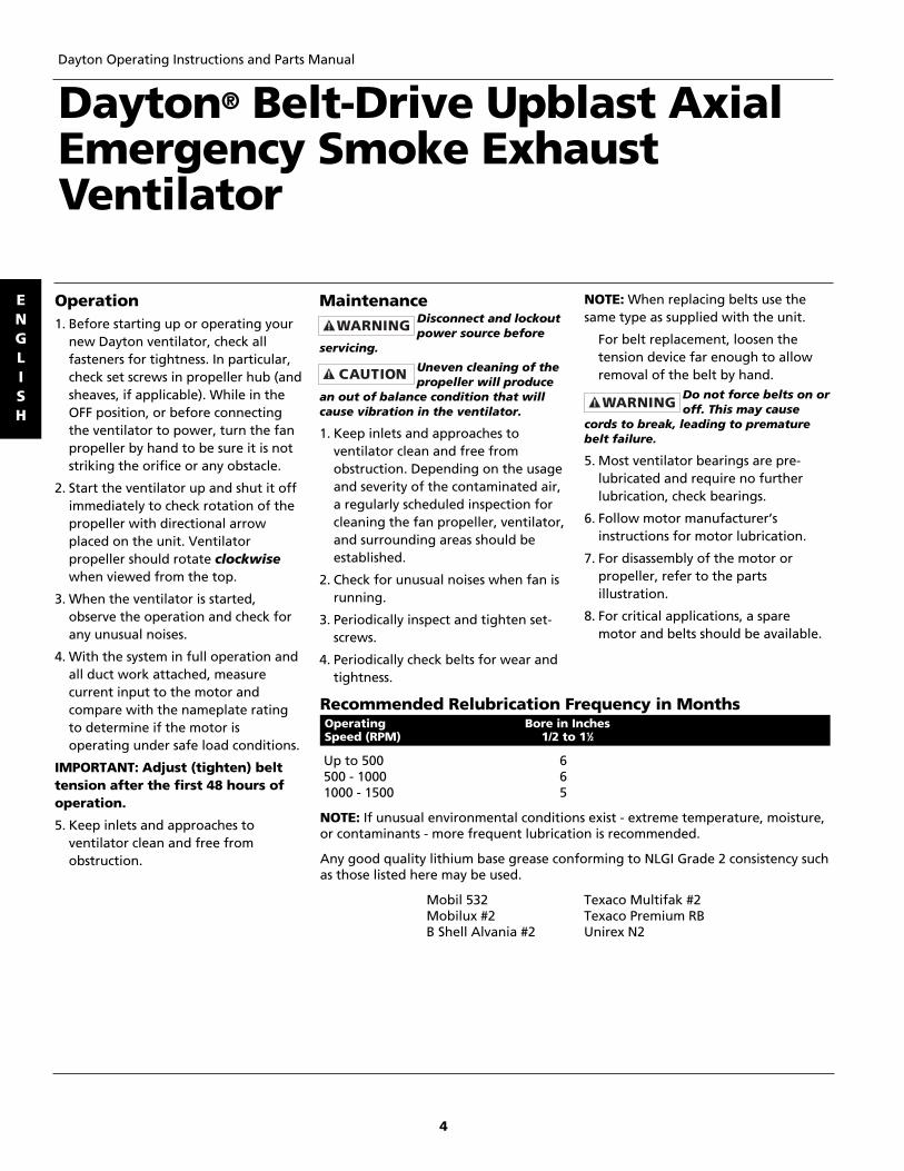
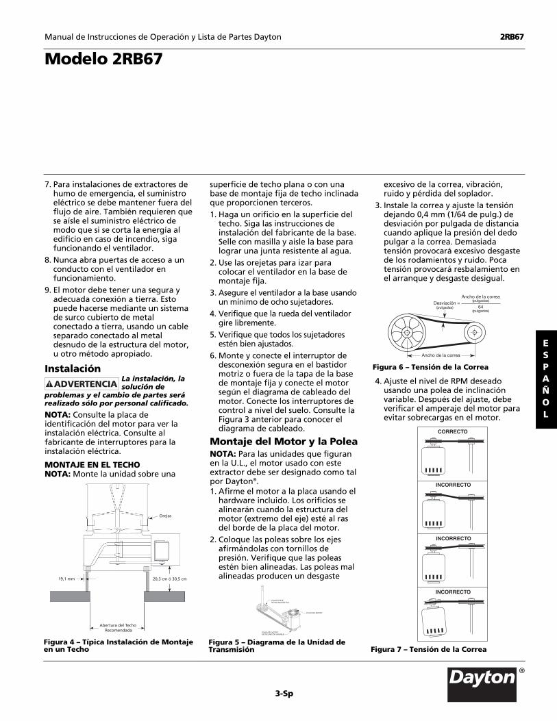
Motor and Pulley MountingNOTE: For U.L. listed units, the motorused with this fan must be designatedas such by Dayton®.1. Secure motor to plate using
hardware provided. Holes will alignwhen the motor frame (shaft end) isflush with the edge of the motorplate.
2. Mount pulleys on shafts securing toshaft with set screw. Check pulleysfor proper alignment. Misalignedpulleys lead to excessive belt wear,vibration, noise and blower loss.
3. Install the belt and adjust thetension to allow for 1/64” ofdeflection per inch of span whenmoderate thumb pressure is appliedto the belt. Too much tension willcause excess bearing wear and noise.Too little tension will cause slippageat startup and uneven wear.
4. Adjust RPM to desired level using avariable pitch pulley. Afteradjustment, motor amperage shouldbe checked to avoid overloading ofthe motor.
Model 2RB67
Dayton Operating Instructions and Parts Manual
MOTOR PLATE
MOTOR PULLEYVARIABLE PITCHTYPE
SHAFT PULLEYFIXED PITCHTYPE
Figure 5 – Drive Package Diagram
Lifting Lugs
8" or 12"3/4"
RecommendedRoof Opening
Figure 4 – Typical Roof MountingInstallation
Deflection = Belt Span (in.)64 in.
Belt Span
Figure 6 – Belt Tension
Figure 7 – Pulley Alignment
CORRECT
WRONG
WRONG
WRONG
ENGLISH
3
®
Operation1. Before starting up or operating your
new Dayton ventilator, check allfasteners for tightness. In particular,check set screws in propeller hub (andsheaves, if applicable). While in theOFF position, or before connectingthe ventilator to power, turn the fanpropeller by hand to be sure it is notstriking the orifice or any obstacle.
2. Start the ventilator up and shut it offimmediately to check rotation of thepropeller with directional arrowplaced on the unit. Ventilatorpropeller should rotate clockwisewhen viewed from the top.
3. When the ventilator is started,observe the operation and check forany unusual noises.
4. With the system in full operation andall duct work attached, measurecurrent input to the motor andcompare with the nameplate ratingto determine if the motor isoperating under safe load conditions.
IMPORTANT: Adjust (tighten) belttension after the first 48 hours ofoperation.
5. Keep inlets and approaches toventilator clean and free fromobstruction.
MaintenanceDisconnect and lockoutpower source before
servicing.
Uneven cleaning of thepropeller will produce
an out of balance condition that willcause vibration in the ventilator.
1. Keep inlets and approaches toventilator clean and free fromobstruction. Depending on the usageand severity of the contaminated air,a regularly scheduled inspection forcleaning the fan propeller, ventilator,and surrounding areas should beestablished.
2. Check for unusual noises when fan isrunning.
3. Periodically inspect and tighten set-screws.
4. Periodically check belts for wear andtightness.
NOTE: When replacing belts use thesame type as supplied with the unit.
For belt replacement, loosen thetension device far enough to allowremoval of the belt by hand.
Do not force belts on oroff. This may cause
cords to break, leading to prematurebelt failure.
5. Most ventilator bearings are pre-lubricated and require no furtherlubrication, check bearings.
6. Follow motor manufacturer’sinstructions for motor lubrication.
7. For disassembly of the motor orpropeller, refer to the partsillustration.
8. For critical applications, a sparemotor and belts should be available.
Dayton Operating Instructions and Parts Manual
Dayton® Belt-Drive Upblast AxialEmergency Smoke ExhaustVentilator
Up to 500 6500 - 1000 61000 - 1500 5
NOTE: If unusual environmental conditions exist - extreme temperature, moisture,or contaminants - more frequent lubrication is recommended.
Any good quality lithium base grease conforming to NLGI Grade 2 consistency suchas those listed here may be used.
Mobil 532 Texaco Multifak #2Mobilux #2 Texaco Premium RBB Shell Alvania #2 Unirex N2
Operating Bore in InchesSpeed (RPM) 1/2 to 11⁄2
Recommended Relubrication Frequency in Months
ENGLISH
4
1
2
3
4
5
6
7
8
9
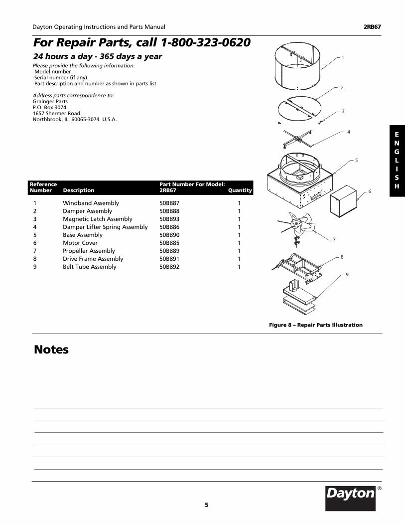
For Repair Parts, call 1-800-323-062024 hours a day - 365 days a yearPlease provide the following information:-Model number-Serial number (if any)-Part description and number as shown in parts list
Address parts correspondence to:Grainger Parts P.O. Box 30741657 Shermer RoadNorthbrook, IL 60065-3074 U.S.A.
1 Windband Assembly 50B887 12 Damper Assembly 50B888 13 Magnetic Latch Assembly 50B893 14 Damper Lifter Spring Assembly 50B886 15 Base Assembly 50B890 16 Motor Cover 50B885 17 Propeller Assembly 50B889 18 Drive Frame Assembly 50B891 19 Belt Tube Assembly 50B892 1
Reference Part Number For Model:Number Description 2RB67 Quantity
Figure 8 – Repair Parts Illustration
Dayton Operating Instructions and Parts Manual 2RB67
Notes
ENGLISH
5
®

DAYTON ONE-YEAR LIMITED WARRANTY. Dayton® Belt-Drive Upblast Axial Exhaust Ventilators, Models covered in this manual, are warranted by DaytonElectric Mfg. Co. (Dayton) to the original user against defects in workmanship or materials under normal use for one year after date of purchase. Any part whichis determined to be defective in material or workmanship and returned to a Grainger branch, shipping costs prepaid, will be, as the exclusive remedy, repairedor replaced at Grainger’s option. For limited warranty claim procedures, see PROMPT DISPOSITION below. This limited warranty gives purchasers specific legalrights which vary from jurisdiction to jurisdiction.
LIMITATION OF LIABILITY. DAYTON SHALL NOT BE LIABLE FOR CONSEQUENTIAL, INCIDENTAL, SPECIAL, EXEMPLARY OR PUNITIVE DAMAGES. DAYTON’SLIABILITY, IN ALL CIRCUMSTANCES, SHALL NOT EXCEED THE PURCHASE PRICE PAID FOR THE PRODUCT THAT GIVES RISE TO ANY LIABILITY.
WARRANTY DISCLAIMER. Dayton has made a diligent effort to provide product information and illustrate the products in this literature accurately; however,such information and illustrations are for the sole purpose of identification, and do not express or imply a warranty that the products are MERCHANTABLE, orFIT FOR A PARTICULAR PURPOSE, or that the products will necessarily conform to the illustrations or descriptions.Except as provided below, no warranty or affirmation of fact, expressed or implied, other than as stated in the “LIMITED WARRANTY” above is made orauthorized by Dayton.
PRODUCT SUITABILITY. Many jurisdictions have codes and regulations governing sales, construction, installation, and/or use of products for certain purposes,which may vary from those in neighboring areas. While Dayton attempts to assure that its products comply with such codes, it cannot guarantee compliance,and cannot be responsible for how the product is installed or used. Before purchase and use of a product, review the product applications, and all applicablenational and local codes and regulations, and be sure that the product, installation, and use will comply with them.
Certain aspects of disclaimers are not applicable to consumer products; e.g., (a) some jurisdictions do not allow the exclusion or limitation of incidental orconsequential damages, so the above limitation or exclusion may not apply to you; (b) also, some jurisdictions do not allow a limitation on how long an impliedwarranty lasts, consequently the above limitation may not apply to you; and (c) by law, during the period of this Limited Warranty, any implied warranties ofimplied merchantability or fitness for a particular purpose applicable to consumer products purchased by consumers, may not be excluded or otherwisedisclaimed.
PROMPT DISPOSITION. Dayton will make a good faith effort for prompt correction or other adjustment with respect to any product which proves to bedefective within limited warranty. For any product believed to be defective within limited warranty, first write or call dealer from whom the product waspurchased. Dealer will give additional directions. If unable to resolve satisfactorily, write to Dayton at address below, giving dealer’s name, address, date, andnumber of dealer’s invoice, and describing the nature of the defect. Title and risk of loss pass to buyer on delivery to common carrier. If product was damaged intransit to you, file claim with carrier.
Manufactured for Dayton Electric Mfg. Co., 5959 W. Howard St., Niles, Illinois 60714 U.S.A.
Dayton Operating Instructions and Parts Manual
Dayton® Belt-Drive Upblast AxialEmergency Smoke ExhaustVentilator
Manufactured for Dayton Electric Mfg. Co.Niles, Illinois 60714 U.S.A.
®
2RB67
®
Ventilator Inoperative 1. Blown fuse or breaker 1. Replace or repair2. Defective motor 2. Replace or repair3. Incorrectly wired 3. Shut power OFF and check wiring for
proper connections4. Broken belts 4. Replace
Insufficient airflow 1. Speed too slow 1. Check for correct drives2. Damper closed 2. Inspect/repair damper3. Belt slippage 3. Replace/adjust tension4. Incorrect propeller rotation 4. Check motor wiring
Excessive noise or vibration 1. Loose propeller or sheaves 1. Tighten set screws2. Mis-aligned sheaves 2. Re-align3. Ventilator base not securely anchored 3. Secure properly4. Fan propeller out of balance 4. Replace propeller
Motor overloads or overheats 1. Propeller RPM too high 1. Check drives2. Shorted motor winding 2. Replace motor3. Incorrect propeller rotation 3. Check motor wiring4. Over/Under line voltage 4. Contact Power Co5. Belt slippage 5. Tighten belt
Symptom Possible Cause(s) Corrective Action
Trouble Shooting ChartENGLISH
®
ESPAÑOL
Formulario 5S5541 Impreso en EE.UU.046321006/268/VCPVP
468878Rev. 2 de octubre 2006
Manual de Instrucciones de Operación y Lista de Partes Dayton 2RB67
Por favor lea y guarde estas instrucciones. Léalas cuidadosamente antes de tratar de montar, instalar, operar o dar mantenimiento alproducto aqui descrito. Protéjase usted mismo y a los demás observando toda la información de seguridad. iEl no cumplir con las instruccionespuede ocasionar daños, tanto personales como a la propiedad! Guarde estas instrucciones para referencia en el futuro.
UL General ó 705Descripción Modelo Nº
Accesorios Opcionales
2RB67 121,9 cm 3,2 cm 132,1 x 132,1 cm
AberturaDiám. de Diám. del Techo
Modelo la Hélice del Eje Recomendada
Dimensiones y Especificaciones (Ver Figura 1)
Base de Montaje Ajustable de 15,2 cm 3C216Base de Montaje Ajustable de 30,5 cm 3C439Base de Montaje Fija de 20,3 cm 4HX45Base de Montaje Fija de 30,5 cm 4HX53
No usar en ningunaaplicacion de
extracción de cocina.
DescripciónLos extractores Dayton están diseñados para edificios industriales y comerciales,así como también, para almacenes, fábricas, fundiciones y laboratorios. El extractoraxial de techo de tiro hacia arriba está fabricado de acero galvanizado de calibregrueso y cuenta con certificación UL para el “control del humo de emergencia”.Temperatura de funcionamiento continua de 48,9ºC (120ºF). Está clasificado para260ºC (500ºF )durante un tiempo mínimo de 4 horas, 537,8ºC (1000ºF) durante untiempo mínimo de 15 minutos e incluye una clasificación de carga de nieve UL-793.UL-793 garantiza que los reguladores de tiro se abrirán en caso de incendio,exigiendo 10 lb. de fuerza ascensional por pie cuadrado. Este ventilador incluye unaconexión con fusible de 73,8ºC (165ºF) en los elevadores del regulador de tiro, untubo para correa con pantalla térmica y rodamientos de alta temperatura Lasorejetas para izar de la abrazadera de izada se proporcionan para un levantamientofácil durante la instalación. La inspección y el mantenimiento se simplifican con el“diseño de motor fuera del flujo de aire”. Una cubierta desmontable del motorpermite un acceso rápido y fácil al motor, la correa y los accionamientos desde laplataforma del tejado.
Dayton Electric Mfg. Co. certifica quelos modelos que aquí aparecen tienenlicencia para llevar el sello de laAMCA. Las mediciones expuestasestán basadas en pruebas yprocedimientos realizados según lasPublicaciones 211 y 311 de la AMCA
y cumplen con los requerimientos del Programade Resultados Certificados de la AMCA.
R
®
AIR
MOVEMENT
AND CONTROL
ASSOCIATION
INTERNATIONAL, INC.
AIRPERFORMANCE
SOUNDand
E53236MH45468
ADVERTENCIA
146,1 cm
75,2 cm
61,9 cm41,9 cm
142,2 cm
182,5 cm
5,7 cm
55,2 cm
Figura 1 – Dimensiones
Suministro de Aire CFM @ Presión EstáticaDiám. de RPM del Máx. Sonidos @ 0,000” 0,125” 0,250” 0,375” 0,500”
Modelo la Hélice HP Ventilador BHP 0,125 SP SP SP SP SP SP
Rendimiento
2RB67 121,9 cm 2 433 2,2 18,4 25642 22583 18650 - -3 496 3,31 23 29373 26836 23563 19730 -5 587 5,49 29 34761 32809 30166 27319 24091
El rendimiento mostrado es para la instalación en línea tipo A, Entrada libre, Salida libre. La medición de energía (BHP) no incluye las pérdidas de transmisión. Los resultados derendimiento no incluyen los accesorios. Los resultados de ruido mostrados son valores de sonora en sonidos del ventilador a 1,5 m (5 pies) en un campo hemisférico libre calculado por elEstándar 301 de la AMCA. Los valores mostrados son para: Instalación Tipo A: Niveles de sonidos del ventilador de entrada libre. El sello de ruido Certified Ratings (Niveles certificados) deAMCA se aplica sólo a niveles de sonidos.
Extractor Axial de Humo deEmergencia de Techo de Tiro Arribay Transmisión por Correa Dayton®
2-Sp
ESPAÑOL
Manual de Instrucciones de Operación y Lista de Partes Dayton 2RB67
Desempaque1. Inspeccione cualquier daño que pueda
haberse producido durante el traslado.2. El daño durante el envío debe ser
reclamado al transporte.3. Verifique pernos, tornillos y tornillos
de presión que puedan haberseaflojado durante el traslado. Vuelva aajustarlos según se requiere. Gire larueda a mano para asegurarse de quegira libremente.
No levante elventilador por sus
paletas; use una eslinga de carga o unaplataforma.
Información General sobreSeguridad al Realizar laInstalación o el Service delVentilador
No dependa decualquier interrumptor
como el único medio de desconexión dela energía cuando realiza la instalacióno el service del ventilador. Siempredesconecte y desactive la fuente deenergía antes de la instalación o elservice. La no desconexión de la energíapuede provocar incendios, shock o dañograve. El motor se reiniciará sinadvertencias después de que se activeel protector térmico. No toque el motor,ya que puede estar muy caliente.
No acerque partes delcuerpo u objetos al
ventilador, a las aberturas del motor o alos propulsores mientras el motor estáconectado a la fuente de energía.
¡No use este equipoen lugares
explosivos!
Se debe tener sumocuidado cuando se
trabaje cerca de los conjuntos elevadoresdel regulador de tiro ya que se puedenproducir lesiones corporales graves o lamuerte. Estos ventiladores tienenelevadores del regulador de tiro de laconexión con fusible para servicio extrapesado bajo una tensión elástica muyalta que se debe fijar con pasadores demodo que no se desengancheaccidentalmente cuando se realice
mantenimiento al ventilador. Loselevadores del regulador de tiro de laconexión con fusible se encuentrandebajo de las paletas de la compuerta demariposa para regulación de tiro. ElDetalle A muestra en donde estarán losdos pasadores de seguridad cuando seenvíen de fábrica. Cuando se realicemantenimiento al ventilador, lospasadores se DEBEN sacar de la posicióndel Detalle A y colocar en la posición delDetalle B. El Detalle A muestra en dondese colocan los dos pasadores deseguridad cuando el ventilador está enservicio.
1. Lea y siga todas las instrucciones y lasnotas preventivas. Asegúrese de quela fuente de energía eléctrica cumplecon los requerimientos de equipos ycódigos locales.
2. El montaje, la instalación y el servicede los ventiladores deben serrealizados por técnicos calificados.Haga realizar todo el trabajo deelectricidad por un electricistacalificado.
3. Siga todos los códigos eléctricos y deseguridad locales de Estados Unidos yCanadá, así como también el CódigoNacional Eléctrico de Estados Unidos(NEC), la Ley de Seguridad y SaludOcupacional (OSHA) y el Comunicado96 de la Asociación Nacional deProtección contra Incendios (NFPA) deEstados Unidos. Conectar a tierra elmotor según el Artículo 250 del NEC(conexión a tierra). Siga el CódigoEléctrico Canadiense (CEC) en Canadá.
4. El motor y el ventilador deben estarconectados a tierra (metal desnudo)en un buen terreno eléctrico, comoun caño de agua en la tierra o unsistema de cableado en tierra.
NOTA: Consulte la Figura 3 para ver eldiagrama de la instalación eléctrica.
En los EstadosUnidos, para reducir
el riesgo de daños a las personas, laOSHA exige el uso de guardas cuando elventilador está instalado a 2,1 metros (7 pies) del suelo o del área de trabajo.
En Canadá, parareducir el riesgo de
daños a las personas, la OSHA exige eluso de guardas cuando el ventiladorestá instalado a menos de 2,5 metros(8,2 pies) del suelo o nivel de pendiente.
5. No tuerza el cable de alimentación nipermita que entre en contacto conobjetos filosos, aceites, grasa,superficies calientes o productosquímicos. Reemplace inmediatamentelos cables dañados.
6. Asegúrese de que la fuente dealimentación cumple con losrequerimientos del equipo.
Extractor Axial de Humo deEmergencia de Techo de Tiro Arribay Transmisión por Correa Dayton®
PRECAUCIÓN
PELIGRO
PELIGRO
PRECAUCIÓN
MOTOR
L1
MOTOR
CAJA-JCAJA-J
SUMINISTRO DE VOLTAJE115/208-230/60/1
SUMINISTRO DE VOLTAJE208-230/460/60/3
L2
L1L2
L3
PRECAUCIÓN
PRECAUCIÓN
Figura 3 – Diagrama de una InstalaciónEléctrica Típica
ADVERTENCIA
- IMPORTANTE -
ELÉCTRICO - Si el motor del ventilador NO seprotege térmicamente, se debe instalar unaprotección remota contra sobrecarga quecuente con una clasificación adecuada encuanto a voltaje, frecuencia, caballos de fuerzay corriente a plena carga por fase. Cuando seconecte a un circuito protegido por fusibles, usefusibles con tiempo de retardo. Para la conexiónde suministro use cables clasificados para almenos 90°C (194°F).
INSTALACIÓN - Cuando conecte la energíaeléctrica a este ventilador, no restrinja elmovimiento del motor. El motor debe tener elmovimiento suficiente para un posible ajustefuturo de la correa o rueda. 454975
Ventiladoreléctricoindicadoparasistemade controlde humo76Y9
Detalle BDetalle A
Ubicación dealmacenamientodel pasador deseguridad
Para evitar el cierremientras se realizamantenimiento alventilador
Figura 2 – Elevador del Regulador de Tiro
ESPAÑOL
3-Sp
®
Manual de Instrucciones de Operación y Lista de Partes Dayton 2RB67
7. Para instalaciones de extractores dehumo de emergencia, el suministroeléctrico se debe mantener fuera delflujo de aire. También requieren quese aísle el suministro eléctrico demodo que si se corta la energía aledificio en caso de incendio, sigafuncionando el ventilador.
8. Nunca abra puertas de acceso a unconducto con el ventilador enfuncionamiento.
9. El motor debe tener una segura yadecuada conexión a tierra. Estopuede hacerse mediante un sistemade surco cubierto de metalconectado a tierra, usando un cableseparado conectado al metaldesnudo de la estructura del motor,u otro método apropiado.
InstalaciónLa instalación, lasolución de
problemas y el cambio de partes serárealizado sólo por personal calificado.
NOTA: Consulte la placa deidentificación del motor para ver lainstalación eléctrica. Consulte alfabricante de interruptores para lainstalación eléctrica.
MONTAJE EN EL TECHONOTA: Monte la unidad sobre una
superficie de techo plana o con unabase de montaje fija de techo inclinadaque proporcionen terceros.1. Haga un orificio en la superficie del
techo. Siga las instrucciones deinstalación del fabricante de la base.Selle con masilla y aisle la base paralograr una junta resistente al agua.
2. Use las orejetas para izar paracolocar el ventilador en la base demontaje fija.
3. Asegure el ventilador a la base usandoun mínimo de ocho sujetadores.
4. Verifique que la rueda del ventiladorgire libremente.
5. Verifique que todos los sujetadoresestén bien ajustados.
6. Monte y conecte el interruptor dedesconexión segura en el bastidormotriz o fuera de la tapa de la basede montaje fija y conecte el motorsegún el diagrama de cableado delmotor. Conecte los interruptores decontrol a nivel del suelo. Consulte laFigura 3 anterior para conocer eldiagrama de cableado.
Montaje del Motor y la PoleaNOTA: Para las unidades que figuranen la U.L., el motor usado con esteextractor debe ser designado como talpor Dayton®.1. Afirme el motor a la placa usando el
hardware incluido. Los orificios sealinearán cuando la estructura delmotor (extremo del eje) esté al rasdel borde de la placa del motor.
2. Coloque las poleas sobre los ejesafirmándolas con tornillos depresión. Verifique que las poleasestén bien alineadas. Las poleas malalineadas producen un desgaste
excesivo de la correa, vibración,ruido y pérdida del soplador.
3. Instale la correa y ajuste la tensióndejando 0,4 mm (1/64 de pulg.) dedesviación por pulgada de distanciacuando aplique la presión del dedopulgar a la correa. Demasiadatensión provocará excesivo desgastede los rodamientos y ruido. Pocatensión provocará resbalamiento enel arranque y desgaste desigual.
4. Ajuste el nivel de RPM deseadousando una polea de inclinaciónvariable. Después del ajuste, debeverificar el amperaje del motor paraevitar sobrecargas en el motor.
Modelo 2RB67
ADVERTENCIA
PLACA DEL MOTOR
POLEA DEL MOTOR DE INCLINACIÓN VARIABLE
POLEA DE EJE DE INCLINACIÓN FIJA
Figura 5 – Diagrama de la Unidad deTransmisión
Orejas
20,3 cm ó 30,5 cm19,1 mm
Abertura del Techo Recomendada
Figura 4 – Típica Instalación de Montajeen un Techo
Desviación =(pulgadas)
Ancho de la correa(pulgadas)
64(pulgadas)
Ancho de la correa
Figura 6 – Tensión de la Correa
CORRECTO
INCORRECTO
INCORRECTO
INCORRECTO
Figura 7 – Tensión de la Correa
ESPAÑOL
4-Sp
Manual de Instrucciones de Operación y Lista de Partes Dayton
Operación1. Antes de comenzar a usar su nuevo
ventilador Dayton, verifique quetodos los sujetadores estén ajustados.En particular, ajuste los tornillos en elcentro de la hélice (y las roldanas, sise aplica). Mientras está apagado, oantes de conectar el ventilador a lafuente de alimentación, gire la ruedadel ventilador a mano paraasegurarse de que no golpea elorificio ni otro obstáculo.
2. Encienda el ventilador y apágueloinmediatamente para verificar larotación de la hélice con la flechadireccional colocada en la unidad. Larueda del ventilador debe girar en elsentido de las agujas del relojcuando se lo mira desde arriba.
3. Cuando el ventilador está encendido,observe su operación y verifique sihay algún ruido inusual.
4. Con el sistema funcionando a pleno ytodos los conductos fijados, mida laentrada de corriente al motor ycompárela con la medición de laplaca de identifiación paradeterminar si el motor está operandoen condiciones de carga segura.
IMPORTANTE: Ajuste (ponga tirante)la tensión de la correa después delas primeras 48 horas de operación.
5. Mantenga las entradas y las áreascercanas al ventilador limpias y sinobstrucciones.
MantenimientoDesconente y cortela fuente de
alimentación antes de realizar elservice.
La limpiezadesigual de la
rueda provocará un desequilibrio queproducirá vibración en el ventilador.
1. Mantenga las entradas y las áreascercanas al ventilador limpias y sinobstrucciones. Según el uso y lagravedad del aire contaminado, debeestablecerse un cronograma regularde inspecciones para limpiar la hélicedel ventilador, el ventilador y lasáreas circundantes.
2. Verifique la presencia de ruidosinusuales cuando el ventilador estéfuncionando.
3. Inspeccione y ajuste periódicamentelos tornillos de presión.
4. Verifique periódicamente el desgastey la tensión de las correas.
NOTA: Cuando cambie las correas, useel mismo tipo que viene con la unidad.
Para cambiar la correa, afloje eldispositivo de tensión lo suficientepara poder quitar la correa a mano.
No fuerce lascorreas. Si lo hace
las correas se romperán, provocandofallas prematuras.
5. La mayoría de los rodamientos de losventiladores viene previamentelubricado y no requiere lubricaciónextra, verifique los rodamientos.
6. Siga las instrucciones del fabricantedel motor en cuanto a su lubricación.
7. Para el desmontaje del motor o lahélice, consulte la ilustración depiezas.
8. Para aplicaciones críticas, debe haberun motor y correas de repuesto.
Extractor Axial de Humo deEmergencia de Techo de Tiro Arribay Transmisión por Correa Dayton®
Hasta 500 6500 - 1000 61000 - 1500 5
NOTA: En caso de condiciones ambientales inusuales (temperatura, humedad ocontaminación extremas) se recomienda mayor frecuencia de lubricación.
Puede usarse una grasa a base de litio de alta calidad según la consistencia Grado 2del NLGI, como las que aquí se enumeran.
Mobil 532 Texaco Multifak #2Mobilux #2 Texaco Premium RBB Shell Alvania #2 Unirex N2
Velocidad Calibre en PulgadasOperativa (RPM) 1/2 a 11/2
Frecuencia Recomendada de Lubricación en Meses
ADVERTENCIA
PRECAUCIÓNADVERTENCIA

ESPAÑOL
5-Sp
®
Manual de Instrucciones de Operación y Lista de Partes Dayton
1
2
3
4
5
6
7
8
9
Para Obtener Partes de Reparación en México Llame al 001-800-527-2331en EE.UU. Llame al 1-800-323-0620Servicio permanente - 24 horas al día al año
Por favor proporciónenos la siguiente información:-Número de modelo-Número de serie (si lo tiene) -Descripción de la parte y número que le corresponde en la lista de partes
Envíe correspondencia relacionada con pedidos de partes a:Grainger PartsP.O. Box 30741657 Shermer RoadNorthbrook, IL 60065-3074 U.S.A.
1 Ensamble de la Banda para viento 50B887 1
2 Ensamble del Regulador de tiro 50B888 1
3 Conjunto de conexión magnética 50B893 1
4 Conjunto de resorte del elevador del regulador de tiro 50B886 1
5 Ensamble de la base 50B890 16 Tapa del Motor 50B885 17 Ensamble de la Hélice 50B889 18 Ensamble de la Estructura
de Transmisión 50B891 19 Conjunto de tubo para correa 50B892 1
Número de Número de Parte para Modelos:Referencia Descripción 2RB67 Cantidad
Figura 8 – Ilustración de Partes de Reparación
Notas
2RB67
Fabricado por Dayton Electric Mfg. Co.Niles, Illinois 60714 U.S.A.
®
ESPAÑOL
Manual de Instrucciones de Operación y Lista de Partes Dayton 2RB67
GARANTÍA LIMITADA DE UN AÑO DAYTON. Los Extractores Axial de Humo de Emergencia de Techo de Tiro Arriba y Transmisión por Correa Dayton®, losmodelos incluidos en este manual, tienen garantía de Dayton Electric Mfg. Co. (Dayton) por defectos de fabricación o materiales durante su uso normal duranteun año a partir de la fecha de compra. Cualquier pieza que se considere con fallas en cuanto al material o la fabricación y se devuelva a una sucursal deGrainger, con los costos de envío previamente pagos, será, como único remedio, reparada o remplazada a criterio de Grainger. Por demanda de garantíalimitada, ver DISPOSICIÓN INMEDIATA a continuación. Esta garantía limitada le da al comprador derechos legales específicos que varían de una jurisdicción aotra.
RESTRICCIÓN DE RESPONSABILIDAD. DAYTON NO SE RESPONSABILIZARÁ POR DAÑOS RESULTANTES, ACCIDENTALES, ESPECIALES, EJEMPLIFICANTES OPUNITIVOS. LA RESPONSABILIDAD DE DAYTON, EN NINGÚN CASO, EXCEDERÁ EL PRECIO DE COMPRA PAGADO POR EL PRODUCTO QUE SUSCITE CUALQUIERRESPONSABILIDAD.
Denegación de Garantía. Dayton se ha esforzado por suministrar información sobre el producto e ilustrar con precisión los productos de este manual; sinembargo, dichas información e ilustraciones sólo son para identificación, y no expresan ni implican una garantía de que los productos son comerciables, o seadaptan a un propósito en particular, o que los productos necesariamente estarán de acuerdo con las ilustraciones o descripciones.Con excepción de lo que se detalla a continuación, ninguna garantía ni afirmación de hecho, expresa o implícita, aparte de lo que se incluye en la “GARANTÍALIMITADA” está hecha o autorizada por Dayton.
APTITUD DEL PRODUCTO. Muchas jurisdicciones tienen códigos y ordenanzas que regulan las ventas, la construcción, la instalación, y/o el uso de productospara ciertos propósitos, que pueden variar con respecto a los de las áreas vecinas. Aunque Dayton procura asegurarse que sus productos cumplan con dichoscódigos, no puede garantizar el cumplimiento, ni puede responsabilizarse por cómo se usa o instala el producto. Antes de comprar o usar un producto, revise lasaplicaciones del producto, y todos los códigos y ordenanzas locales y nacionales que se aplican, y asegúrese de que el producto, su instalación y su uso cumplancon los mismos.
Ciertos aspectos de la denegación no se aplican a productos del consumidor; por ej., (a) algunas jurisdicciones no permiten la exclusión o la limitación de dañosaccidentales o resultantes, por lo que la limitación o exclusión mencionadas anteriormente, pueden no aplicarse a usted; (b) además, algunas jurisdicciones nopermiten una limitación sobre la duración de una garantía implícita, en consecuencia, la limitación mencionada anteriormente puede no aplicarse a usted; y (c) por ley, durante el período de esta Garantía Limitada, cualquier garantía implícita de comerciabilidad o aptitud para un propósito en particular que seaplique a productos del consumidor adquiridos por consumidores, no puede ser excluída ni rechazada.
DISPOSICIÓN INMEDIATA. Dayton hará un esfuerzo de buena fe por efectuar una inmediata corrección u otro ajuste con respecto a cualquier producto quedemuestretener fallas dentro de la garantía limitada. En caso de existir un producto con fallas dentro de la garantía limitada, escriba o llame al distribuidor aquien le compró el producto. Éste le indicará qué hacer. Si el problema no se resuelve de manera satisfactoria, escriba a Dayton a la dirección que figura acontinuación, indicando nombre del distribuidor, dirección, fecha y número de la factura del distribuidor, y describa la naturaleza de la falla. Título y riesgo depérdida pasan al comprador en la entrega a la compañía de transporte. Si el producto se dañó durante el transporte, presente el reclamo al transporte.
Fabricado por Dayton Electric Mfg. Co., 5959 W. Howard St., Niles, Illinois 60714 U.S.A.
Extractor Axial de Humo deEmergencia de Techo de Tiro Arribay Transmisión por Correa Dayton®
El ventilador no funciona 1. Fusible o disyuntor quemado 1. Cambiar o reparar2. Motor con fallas 2. Cambiar o reparar3. Los cables están mal colocados 3. Corte la fuente de alimentación y verifique la
instalación eléctrica4. Correas rotas 4. Cambiar
Flujo de aire insuficiente 1. La velocidad es demasiado lenta 1. Verificar la propulsión2. Regulador de tiro cerrado 2. Inspeccionar/reparar3. Resbalamiento de la correa 3. Cambiar/ajustar tensión4. Rotación de la hélice incorrecta 4. Verificar la instalación eléctrica del motor
Demasiado ruido o vibración 1. Hélice o roldanas flojas 1. Ajuste los tornillos de presión2. Roldanas mal alineadas 2. Volver a alinear3. La base del ventilador no está bien afirmada 3. Ajustar bien4. La hélice del ventilador está desequilibrada 4. Cambiar la hélice
El motor se sobrecarga o se 1. La RPM de la hélice es demasiado alta 1. Verificar propulsiónrecalienta 2. Bobinas del motor más cortas 2. Cambiar motor
3. Rotación de la hélice incorrecta 3. Verificar la instalación eléctrica del motor4. Poco/demasiado voltaje 4. Consultar al proveedor del servicio de energía5. Resbalamiento de la correa 5. Tensar correa
Síntoma Causa(s) Posible(s) Medida Correctiva
Cuadro de Solución de Problemas