property damage! retain instructions for future …€¦ · dayton ® portable evaporative cooler...
TRANSCRIPT

Form 5S6495
ENGLISH
ESPAÑOL
Printed in Mexico096631109/223/VCPVP
INM100
Dayton® PortableEvaporative Cooler
Operating Instructions & Parts Manual 6RJZ3 and 6RJZ4
Please read and save these instructions. Read carefully before attempting to assemble, install, operate or maintain the product described.Protect yourself and others by observing all safety information. Failure to comply with instructions could result in personal injury and/orproperty damage! Retain instructions for future reference.
DescriptionThe Industrial Evaporative Cooler is a natural way to condition the atmosphere. It cools by combining water evaporation with air movement, through carefullydesigned and manufactured equipment, providing maximum efficiency and safety.This air conditioning system, in addition to being economical, gives more benefitsthan other air conditioning systems for homes and businesses. The system does not use refrigerants or compressors; it cools by simply moving air through a surface composed of moist filters. Air temperature drops when a liquid, in this case water, transforms into gas. Humidity is not perceived, since the air in the room is renewed approximately every two minutes, providing a comfortablecooling effect. Continuous air circulation is a vital aspect of the cooling process in this equipment, and gives it a distinct advantage over air conditioning byrefrigeration.
UnpackingHandle carefully. Check the packing list to account for all items. Visually inspect for shipping damage. If damaged, immediately file a claim with the carrier.
Figure 1
6RJZ3 28 (71.12) 38.50 (97.79) 28 (71.12) 16.5 (41.91) 19.5 (49.53) 14.0 (35.56) 23.75 (60.33)6RJZ4 22 (55.88) 34.5 (87.63) 22 (55.88) 16.38 (41.6) 14.13 (35.9) 6 (15.24) 18.5 (47.0)
Dimensions – in. (cm)Cabinet Measures Grill Measures Drain Reference
Model A B C D E H I
C
DA
B
H
E
G
I
6RJZ3 0.333 HP 120 V 6.5 A 60 Hz 16-18 15 A 88.2 (40) 10.4 gal. (40 liters)6RJZ4 0.125 HP 120 V 2.6 A 60 Hz 16-18 15 A 66.2 (30) 6.3 gal. (24 liters)
SpecificationsGross Wt. Tank
Model Motor Volts Amperage Freq. AWG Ga Fuse lbs (kg) Capacity
2
ENGLISH
General Safety Information1. Read all the instructions beforeoperating the air cooler.
2. This product operates at 110-120VAC, 60 Hz only.
3. Do not use with a damaged cord orplug, and keep the cord away fromheated surfaces.
If the power supplycord is damaged,
it must be replaced by the manufactureror its service agent or a similarlyqualified person in order to avoid a hazard.
4. Do not insert any foreign objects intothe air inlet or outlet, body injury or property damage may occur.
5. Do not operate this product near anopen fire, it may ignite and causefire, resulting in body injury orproperty damage.
6. Do not operate in areas wheregasoline, paint or other flammableliquids are used or stored.
Prior to cleaning orother maintenance,
the air cooler must be unplugged.
7. Always unplug the power cord fromreceptacle when the air cooler is notin use, before cleaning, replacingparts, or before moving to anotherlocation.
8. Do not use this appliance in theimmediate surrounds of a bath, a shower or a swimming pool orother liquids.
9. Do not plug the cord into electricoutlet with wet hands, an electricshock may result.
10. Never attempt to disassemble oralter the product in any way notinstructed by this manual. Shock,fire, or bodily injury may occur.
To reduce the risk offire or electric
shock, do not use this fan with anysolid-state speed control device.
11. Use Only on GFCI ProtectedReceptacles.
READ AND SAVE THESEINSTRUCTIONS!
InstallationThe air conditioner does not require anyother installation; just add water, plugit in and it is ready to give you hours of cool comfort.
FLOAT VALVE
A valve should be installed connecting a water supply line to the unit, placingit in an accessible location where thewater flow may be easily controlled,opened and closed.
If you are going to connect a water lineto the system, consider the following list of parts:
– 1/2” (12.7 mm) water valve
– Male type reduction from 1/2” (12.7 mm) to 1/4” (6.3 mm)
– 1/4” (6.3 mm) conical nut
– 1/4” (6.3 mm) diameter copper tube
– Water sealing Teflon tape
NOTE: These components are only forthe water supply system. Coolers have a float with an external connection in the accessories bag.
1. Remove all the plastic nuts that come assembled with the float.
2. Locate the opening in the coolerclosest to the water tank and pass the thread of the float screw throughthis section.
3. Tighten the float with the plastic nut.
4. Pass the water feed tube through theplastic barrel nut, and if necessary,countersink the tube.
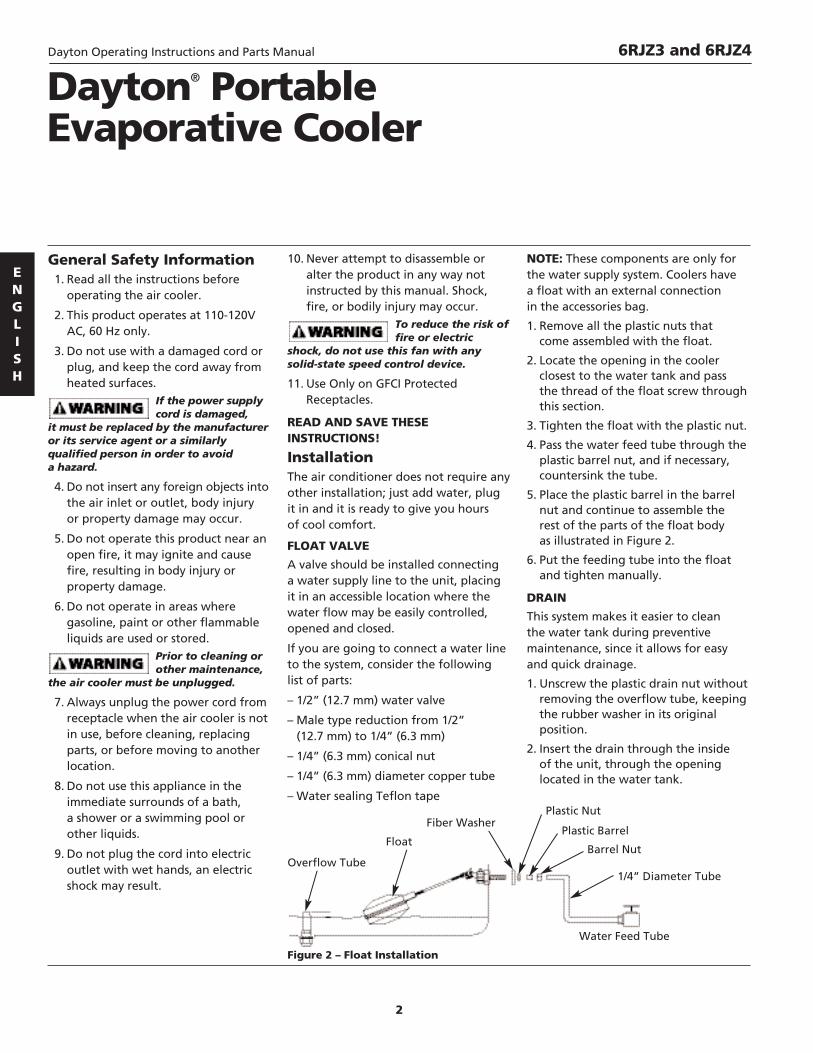
5. Place the plastic barrel in the barrelnut and continue to assemble the rest of the parts of the float body as illustrated in Figure 2.
6. Put the feeding tube into the floatand tighten manually.
DRAIN
This system makes it easier to clean the water tank during preventivemaintenance, since it allows for easyand quick drainage.
1. Unscrew the plastic drain nut withoutremoving the overflow tube, keepingthe rubber washer in its originalposition.
2. Insert the drain through the inside of the unit, through the openinglocated in the water tank.
Dayton® PortableEvaporative Cooler
6RJZ3 and 6RJZ4Dayton Operating Instructions and Parts Manual
Figure 2 – Float Installation
Barrel Nut
1/4” Diameter Tube
Plastic Barrel
Plastic NutFiber Washer
Float
Overflow Tube
Water Feed Tube

3
ENGLISH
Installation (Continued)3. Screw the plastic nut on from theoutside of the cabinet (tightenmanually).
4. Fill the tank with water, making sure to maintain a depth of 2.36”,having previously moistened theaspen filters of your cooler.
NOTE: It is recommendable that greaseor Vaseline be used on the drain screwthread to make it easier to unscrewduring maintenance.
ELECTRICAL CONNECTIONAll electricalconnections must
comply with local construction andsafety regulations, and be performed by qualified personnel.
Connect the unit to a 120 V~ +/-10% 60 Hz current, 1 phase (see WiringDiagram, page 4). The power supply forthe cooler should be connected directlyto the main switch box. Make sure that the power switches are in the offposition before operating your cooler.
A maximum distance of 98 feet of wireis recommended.
If the power wire is damaged, it
should be replaced by a service agent or qualified personnel to avoid risk.
Check before start up:
– The cabinet is level.
– The blower spins freely.
– The amperage of the unit complieswith the electrical specificationscontained in this manual.
– The float automatically stops thewater at the recommended level.
– Pump start up and humidification of the filters is correct.
– Check that the nuts are properlytightened.
– The water supply is stable and has no leaks.
When your cooler is working, leave a window or door open in order tokeep a constant air flow and to avoidany accumulation of humidity and heat.
Your cooler does not cool correctlywhen air flow is restricted from exitinga room. This causes a decrease in thecooling level due to an increase in thehumidity level in the room. Therefore,an open area of at least 1 x 1 feet for every 500 CFM of injected air is required.
MaintenanceMaintenance is key for your cooler tohave an effective and long service life.
To avoid unnecessary part replacementskeep your unit in good condition.
Do not use cleaners, additives or scents.The use of these products may reducethe life of your equipment.
REQUIRED MAINTENANCE
General unit cleaning: Beginning and End of Season
Motor lubrication: Beginning and Middle of Season
Shut off the water flow: End of Season
Filter change: Beginning and Middle of Season
Remove water and clean the tank: End of Season
Make sure nuts are not loose: Beginning and End of Season
UNIT CLEANING1. Be sure to turn off the power supplybefore performing maintenance.
2. Remove the side and back walls of the cabinet.
3. Completely drain the cabinet byremoving the drain from the base.
4. Using a brush with soft plastic bristles,clean the water tank by removing thedust and accumulated mineral salts(only use water to clean the tank).
5. Put the drain back into its originalposition. Make sure there are noleaks.
6. If you are not going to use your unitfor more than 30 days, turn off themain water and power supply.
Models 6RJZ3 and 6RJZ4Dayton Operating Instructions and Parts Manual
Figure 3 – Drain Installation
Overflow Tube
Plastic Drain
Rubber Washer
Plastic Nut
CoolerBottom
Figure 4 – Air Flow
Yes
No

4
ENGLISH
Maintenance (Continued)WATER PUMP CLEANING1. Disconnect the pump from theconnector.
2. Carefully remove the lid of theimpeller placed at the lower part of the pump. Use soapy water and asmall soft bristle brush to wash theimpeller and lid. (When cleaning the impeller, slightly tilt the pump.Do not let water touch the pump,which would damage it.)
3. Manually turn the pump impeller to get rid of any foreign material. Do NOT force.
4. Remove the upper lid with a flat head or box nutdriver (5/16”) and a 6” pipe wrench or a 5/16” wrench.Place the pump into a horizontalposition and unscrew the nut.
5. Check that the shaft spins freely. Do NOT force.
6. Lubricate the motor pump byapplying four to six drops of light oil, to keep the brass bushings from sticking.
7. Reinstall the upper lid with screws and nuts.
8. Connect the pump.
IMPORTANT: If the impeller or thepump shaft are stuck, lubricate thepump motor and let it set for at least four hours.
PUMP FILTER/SCREEN CLEANING
Use a soft bristle brush to removeaccumulated dust and scaling.
NOTE: Never remove the screen, asremoval may cause contaminants toobstruct pump.
CHANGING THE FILTER1. Using pliers, unbend the points of the supports and remove them fromthe wall.
2. Remove the dirty filters.
3. Clean the wall body and the uppercanal. Use water and a soft bristlebrush only.
4. Place the new filters into the walls.Make sure that the filters are wellmoistened before putting them into place.
5. Place the supports into their originalposition once maintenance has beenperformed.
NOTE: Never operate the unit withoutthese parts in place. Doing so maygenerate an overload and damage the motor.
BELT ADJUSTMENT
The adjustable belt and pulleys arefactory set. Any alteration to the air flowsystem should be done by an authorizedtechnician.
Before any adjustment is made, unplugthe cooling system.
The appropriate belt tension andalignment is an important factor for the efficient operation of the unit. Donot adjust the belt tension by changingthe pulleys diameter. Adjust thebrackets that hold the motor to themotor base only.
Due to wear and use, the belt tends toloosen, therefore, check for propertension during maintenance.
To adjust the belt tension, loosen thethree screws on the motor brackets (usea 7/16 inch or an adjustable wrench).Once loosened the motor can then berepositioned to apply more tension tothe belt.
Dayton® PortableEvaporative Cooler
6RJZ3 and 6RJZ4Dayton Operating Instructions and Parts Manual
Figure 6 – Water Pump Cleaning
Figure 7 – Changing the Filter
Filter Supports
Aspen HeatFilter
Irrigation Canal
Wall Body
Figure 5 – Water Pump Cleaning
Impeller Lid
Impeller

5
ENGLISH
Maintenance (Continued)Belt tension should be adjusted to allowfor 1.2 cm (1/2”) to 2 cm (3/4”) offlexing on each side of pulley.
Once the required belt tension isreached, retighten set screws on thebracket.
PULLEY ADJUSTMENT
Incorrect pulley adjustment andalignment will affect performance byreducing airflow, raising amperage, orcausing motor to overheat.
To adjust pulleys loosen the set screwsand align the motor pulley with theturbine pulley vertically by movingoutwards or inwards on the shaft of themotor. A straight edge should be usedwhen aligning pulleys. After adjustmentretighten set screws. Turn the turbinepulley manually to make sure it misses theturbine box and that the motor pulleydoes not make contact with the motor.
BELT ALIGNMENT
To vertically align the belt, loosen theset screw of the driving pulley (use a5/32” Allen wrench) and move itoutwards or inwards as necessary untilthe correct alignment between bothpulleys is reached.
1. An overtightened belt will increase theamperage and overheat the motor.Too little tension will cause slippage atstartup and a schreechy sound.
2. Find the motor amperage engravedon the specifications plate.
3. Turn ON the motor and make sure itis turning in the right direction.
4. Use a tong ammeter to verify theamperage.
5. Check motor amperage with windowsand doors open.
BEARING AND MOTOR LUBRICATION
De-energize yourequipment before working nearor on the motor to avoid personalrisks.
• The bearings and the motor areequipped to allow bearings to begreased and motor oiled.
• Grease the bearings of the motor shaftslowly, rotating the shaft if possibleuntil a small amount of new greaseappears.
• Pull up the oil box cap and apply atleast six drops of oil. Close the cap.
• Use SAE-10-W-20 oil to prevent earlywear out.
• Lubricate the motor and bearings atleast twice a year.
Models 6RJZ3 and 6RJZ4Dayton Operating Instructions and Parts Manual
Figure 8
Figure 9
Figure 10
BearingLubrication
MotorLubrication
Oil Fill
1/2” of flex
Adjustable Pulley
Turbine Pulley
MotorBracket
NO YES
6
ENGLISH
Dayton® PortableEvaporative Cooler
6RJZ3 and 6RJZ4Dayton Operating Instructions and Parts Manual
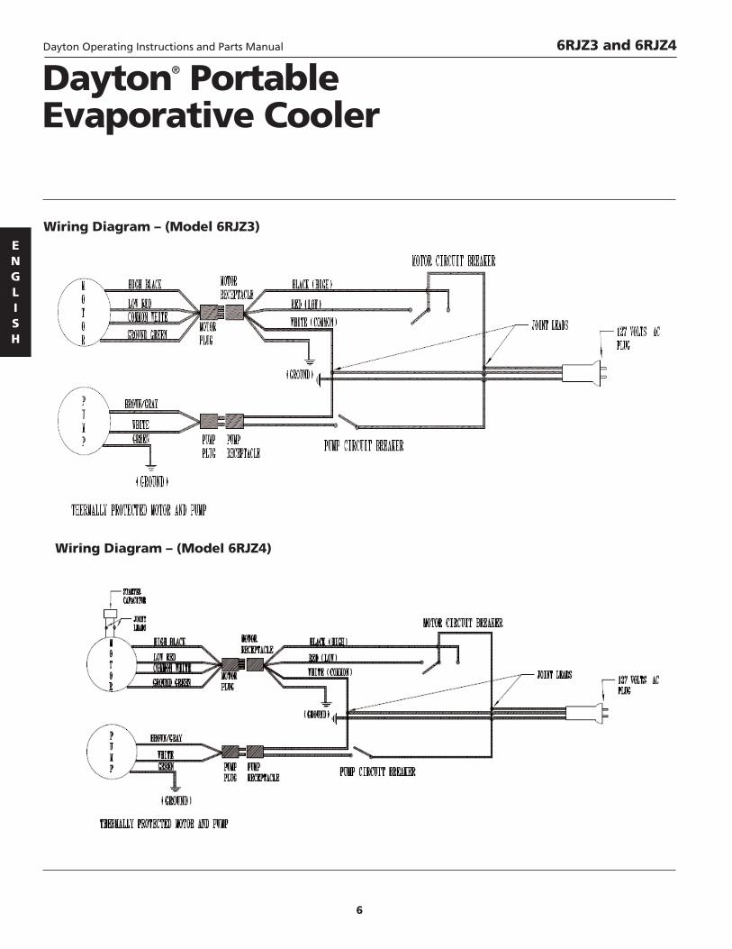
Wiring Diagram – (Model 6RJZ4)
Wiring Diagram – (Model 6RJZ3)

7
ENGLISH
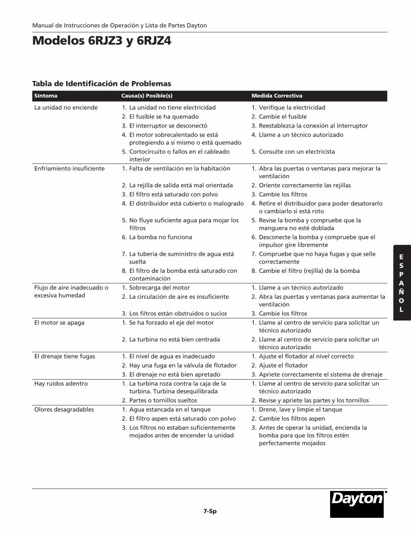
Models 6RJZ3 and 6RJZ4
Symptom Possible Cause(s) Corrective Action
The unit does not start
Insufficient cooling
Inadequate air flow or excessive humidity
The motor shuts off
Drain leaking
Sounds inside
Unpleasant smells
1. The unit does not have electricity
2. The fuse blew
3. The switch got disconnected
4. The overheated motor is protectingitself/burnt
5. Internal wiring failures/short circuit
1. Lack of ventilation in the room
2. Output grid is directed incorrectly
3. The filter is saturated with dust
4. The distributor is covered or broken
5. Not enough water flows to wet the filters
6. The pump does not work
7. The water feed piping is loose
8. The pump filter is saturated withcontamination
1. Motor overload
2. Air circulation is insufficient
3. Filters are obstructed or dirty
1. The motor shaft is forced
2. The turbine is not well centered
1. The water level is inadequate
2. There is a leak in the float valve
3. The drain is not tightened correctly
1. The turbine rubs against the turbine box.Unbalanced turbine
2. Loose parts or screws
1. Stagnant water in the tank
2. The aspen filter is saturated with dust
3. The filters were not wet enough beforeturning on the unit
1. Check the electricity
2. Change the fuse
3. Reestablish the connection to the switch
4. Call an authorized technician
5. Consult an electrician
1. Open the doors or windows to improveventilation
2. Correctly direct the grids
3. Change the filters
4. Remove the distributor in order to unclog it or change it if broken
5. Check the pump, and check that the hose isnot bent
6. Disconnect the pump and check that theimpeller spins freely
7. Check for leaks and that it seals properly
8. Change the pump filter (screen)
1. Call an authorized technician
2. Open doors and windows to increaseventilation
3. Change the filters
1. Call the service center for an authorizedtechnician
2. Call the service center for an authorizedtechnician
1. Adjust the float to the correct level
2. Adjust the float
3. Correctly tighten the drainage system
1. Call the service center for an authorizedtechnician
2. Check and tighten parts and screw
1. Drain, wash and clean the tank
2. Change aspen filters
3. Before operating the unit, turn on the pumpso that the filters may be perfectly wet
Troubleshooting Chart
Dayton Operating Instructions and Parts Manual

Dayton Operating Instructions and Parts Manual 6RJZ3
For Repair Parts, call 1-800-323-062024 hours a day – 365 days a yearPlease provide following information:-Model number-Serial number (if any)-Part description and number as shown in parts list
8
ENGLISH
ENGLISH
Ref. Part No. Description No. Qty.
Ref. Part No. Description No. Qty.
1 Filter HV120014AG 12 Water Pump 3CB58 13 Turbine pulley 3X923 14 Motor pullel 3X765 15 Water Distributor HV120003G 16 Front grill HV120012AG 17 Motor 2HTK5 18 Bearings 2X529 29 Water hose HV120010G 1
10 Motor & pump receptacles HV120001G 111 Float 2X768 112 Overflow pipe HV120009G 113 Motor Plug HV120006G 114 Motor & pump switches HV120011G 115 V-belt 3X699 1

9
ENGLISH
Dayton Operating Instructions and Parts Manual
For Repair Parts, call 1-800-323-062024 hours a day – 365 days a yearPlease provide following information:-Model number-Serial number (if any)-Part description and number as shown in parts list
6RJZ4
1 Filter HV120014G 12 Water Pump 3CB58 13 Water distributor HV120002G 14 Front grill HV120013AG 15 Motor assy HV10007G 16 Water hose HV120010G 17 Motor & pump receptacles HV120001G 1
8 Float 2X768 19 Overflow pipe HV120009G 110 Motor plug HV120006G 111 Motor & pump switches HV120011G 1
Ref. Part No. Description No. Qty.
Ref. Part No. Description No. Qty.

ENGLISH
LIMITED WARRANTY
DAYTON ONE-YEAR LIMITED WARRANTY. DAYTON® INDUSTRIAL EVAPORATIVE COOLER, MODELS COVERED IN THISMANUAL, ARE WARRANTED BY DAYTON ELECTRIC MFG. CO. (DAYTON) TO THE ORIGINAL USER AGAINST DEFECTS INWORKMANSHIP OR MATERIALS UNDER NORMAL USE FOR ONE YEAR AFTER DATE OF PURCHASE. ANY PART WHICH ISDETERMINED TO BE DEFECTIVE IN MATERIAL OR WORKMANSHIP AND RETURNED TO AN AUTHORIZED SERVICE LOCATION,AS DAYTON DESIGNATES, SHIPPING COSTS PREPAID, WILL BE, AS THE EXCLUSIVE REMEDY, REPAIRED OR REPLACED ATDAYTON’S OPTION. FOR LIMITED WARRANTY CLAIM PROCEDURES, SEE “PROMPT DISPOSITION” BELOW. THIS LIMITEDWARRANTY GIVES PURCHASERS SPECIFIC LEGAL RIGHTS WHICH VARY FROM JURISDICTION TO JURISDICTION.
LIMITATION OF LIABILITY. TO THE EXTENT ALLOWABLE UNDER APPLICABLE LAW, DAYTON’S LIABILITY FOR CONSEQUENTIALAND INCIDENTAL DAMAGES IS EXPRESSLY DISCLAIMED. DAYTON’S LIABILITY IN ALL EVENTS IS LIMITED TO AND SHALL NOTEXCEED THE PURCHASE PRICE PAID.
WARRANTY DISCLAIMER. A DILIGENT EFFORT HAS BEEN MADE TO PROVIDE PRODUCT INFORMATION AND ILLUSTRATETHE PRODUCTS IN THIS LITERATURE ACCURATELY; HOWEVER, SUCH INFORMATION AND ILLUSTRATIONS ARE FOR THE SOLEPURPOSE OF IDENTIFICATION, AND DO NOT EXPRESS OR IMPLY A WARRANTY THAT THE PRODUCTS ARE MERCHANTABLE,OR FIT FOR A PARTICULAR PURPOSE, OR THAT THE PRODUCTS WILL NECESSARILY CONFORM TO THE ILLUSTRATIONS ORDESCRIPTIONS. EXCEPT AS PROVIDED BELOW, NO WARRANTY OR AFFIRMATION OF FACT, EXPRESSED OR IMPLIED, OTHERTHAN AS STATED IN THE “LIMITED WARRANTY” ABOVE IS MADE OR AUTHORIZED BY DAYTON.
Technical Advice and Recommendations, Disclaimer. Notwithstanding any past practice or dealings or trade custom,sales shall not include the furnishing of technical advice or assistance or system design. Dayton assumes no obligations orliability on account of any unauthorized recommendations, opinions or advice as to the choice, installation or use ofproducts.
Product Suitability.Many jurisdictions have codes and regulations governing sales, construction, installation, and/or use of products for certain purposes, which may vary from those in neighboring areas. While attempts are made to assure thatDayton products comply with such codes, Dayton cannot guarantee compliance, and cannot be responsible for how theproduct is installed or used. Before purchase and use of a product, review the product applications, and all applicablenational and local codes and regulations, and be sure that the product, installation, and use will comply with them.
Certain aspects of disclaimers are not applicable to consumer products; e.g., (a) some jurisdictions do not allow the exclusionor limitation of incidental or consequential damages, so the above limitation or exclusion may not apply to you; (b) also,some jurisdictions do not allow a limitation on how long an implied warranty lasts, consequently the above limitation may not apply to you; and (c) by law, during the period of this Limited Warranty, any implied warranties of impliedmerchantability or fitness for a particular purpose applicable to consumer products purchased by consumers, may not be excluded or otherwise disclaimed.
Prompt Disposition. A good faith effort will be made for prompt correction or other adjustment with respect to anyproduct which proves to be defective within limited warranty. For any product believed to be defective within limitedwarranty, first write or call dealer from whom the product was purchased. Dealer will give additional directions. If unable toresolve satisfactorily, write to Dayton at address below, giving dealer’s name, address, date, and number of dealer’s invoice,and describing the nature of the defect. Title and risk of loss pass to buyer on delivery to common carrier. If product wasdamaged in transit to you, file claim with carrier.
Manufactured for Dayton Electric Mfg. Co., 5959 W. Howard St., Niles, Illinois 60714-4014 U.S.A.
Dayton® PortableEvaporative Cooler
6RJZ3 and 6RJZ4Dayton Operating Instructions and Parts Manual
Manufactured for Dayton Electric Mfg. Co.Niles, Illinois 60714 U.S.A.

Form 5S6495 Printed in Mexico096631109/223/VCPVP
INM100
Enfriador EvaporativoPortátil Dayton®
Manual de Instrucciones de Operación y Lista de Partes 6RJZ3 and 6RJZ4
Por favor lea y guarde estas instrucciones. Léalas cuidadosamente antes de tratar de montar, instalar, operar o dar mantenimiento al productoaquí descrito. Protéjase usted mismo y a los demás observando toda la información de seguridad. ¡El no cumplir con las instrucciones puedeocasionar daños, tanto personales como a la propiedad! Guarde estas instrucciones para referencia en el futuro.
DescripciónEl Enfriador evaporativo industrial es una forma natural para acondicionar laatmósfera. Éste enfría mediante la combinación de la evaporación del agua con elmovimiento de aire, a través de un equipo cuidadosamente diseñado y fabricado,que brinda una eficacia y seguridad máxima. Además de ser económico, estesistema de aire acondicionado brinda más beneficios que otros sistemas de aireacondicionado para hogares y negocios. El sistema no utiliza refrigerantes nicompresores; sencillamente enfría moviendo aire a través de una superficiecompuesta de filtros húmedos. La temperatura del aire desciende cuando unlíquido, como el agua, se transforma en gas. La humedad no se percibe, porque elaire en la habitación es renovado aproximadamente a cada dos minutos, lo cualproporciona un efecto de enfriamiento confortable. La circulación continua del airees un aspecto vital del proceso de enfriamiento en este equipo, y le proporcionauna notable ventaja sobre el acondicionamiento del aire por refrigeración.
DesempaqueManipule con cuidado. Asegúrese de contar con todos los artículos que aparecenen la lista de empaque. Inspeccione visualmente si ocurrieron daños durante elenvío. De encontrarse daños, deberá enviarse de inmediato una reclamación a lacompañía transportista.
ESPAÑOL
Figura 1
6RJZ3 28 (71.12) 38.50 (97.79) 28 (71.12) 16.5 (41.91) 19.5 (49.53) 14.0 (35.56) 23.75 (60.33)6RJZ4 22 (55.88) 34.5 (87.63) 22 (55.88) 16.38 (41.6) 14.13 (35.9) 6 (15.24) 18.5 (47.0)
Dimensiones – cm (pulg.)Dimensiones del gabinete Dimensiones de la rejilla Referencia del drenaje
Modelo A B C D E H I
6RJZ3 0.333 HP 120 V 6.5 A 60 Hz 16-18 15 A 88.2 (40) 10.4 gal. (40 liters)6RJZ4 0.125 HP 120 V 2.6 A 60 Hz 16-18 15 A 66.2 (30) 6.3 gal. (24 liters)
EspecificacionesPeso bruto Capacidad
Modelo Motor Voltios Amperaje Frec. Calibre AWG Fusible kg (lb) del tanque
C
DA
B
H
E
G
I

2-Sp
ESPAÑOL
Información de SeguridadGeneral1. Lea todas las instrucciones antes deutilizar el enfriador de aire.
2. Este producto funciona sólo con 110-120 V CA, 60 Hz.
3. No lo utilice si el cordón o el enchufeestán dañados, y mantenga el cordónlejos de toda superficie caliente.
Si el cordón dealimentación
eléctrica está dañado, deberá serreemplazado por el fabricante o suagente de servicio o una personasimilarmente calificada a fin de evitarun peligro.
4. No inserte objetos extraños en laentrada o salida de aire, ya que esopodría producir lesiones corporales odaño a la propiedad.
5. No opere este producto cerca de unfuego abierto, porque se podríaencender y causar un incendio, locual podría resultar en lesionescorporales o daño a la propiedad.
6. No utilice la unidad en las áreas dondese emplee o almacene gasolina,pintura u otros líquidos inflamables.
El enfriador de aire se debe
desenchufar antes de limpiarlo ohacerle cualquier otro mantenimiento.
7. Siempre desenchufe el cordón dealimentación del receptáculo cuandono se utilice el enfriador de aire,antes de limpiarlo, reemplazarpartes, o antes de moverlo a otrolugar.
8. No utilice este aparato cerca de unbaño, una ducha o una piscina uotros líquidos.
9. No inserte el enchufe en eltomacorriente con las manoshúmedas, ya que eso podríaocasionarle un choque eléctrico.
10. Nunca intente desarmar o modificarel producto en forma alguna noindicada por este manual. Podríanproducirse lesiones corporales,incendio o un choque eléctrico.
Para reducir elriesgo de incendio
o choque eléctrico, no utilice esteventilador con dispositivos de estadosólido de control de velocidad.
11. Utilice únicamente en receptáculosprotegidos con interruptor de fallade puesta tierra.
¡LEA Y GUARDE ESTASINSTRUCCIONES!
InstalaciónEl acondicionar de aire no requiereninguna otra instalación, sólo agrégueleagua, enchúfelo, y está listo parabrindarle horas de enfriamientoconfortable.
VALVULA DE FLOTADORSe debe instalar una válvula en la líneade suministro de agua para la unidad, yse debe colocar la válvula en un lugaraccesible donde se pueda controlar, abriro cerrar fácilmente el flujo de agua.
Si va a conectar una línea de agua en elsistema, tome en cuenta la siguientelista de partes:
– Válvula de agua de 12.7 mm (1/2 pulg.)
– Reductor tipo macho de 12.7 mm (1/2pulg.) a 6.3 mm (1/4 pulg.)
– Tuerca cónica de 6.3 mm (1/4 pulg.)
– Tubo de cobre de 6.3 mm (1/4 pulg.)de diámetro
– Cinta de Teflón para sellar conexionesde agua
AVISO: Estos componentes son sólopara el sistema de suministro de agua.Los enfriadores tienen un flotador conuna conexión externa en la bolsa deaccesorios.
1. Extraiga todas las tuercas de plásticoque vienen instaladas con el flotador.
2. Localice la abertura en el enfriadormás cercana al tanque de agua y pasela rosca del tornillo del flotador através de esta sección.
3. Apriete el flotador con la tuerca deplástico.
4. Pase el tubo de alimentación de agua através de la tuerca cilíndrica de plástico,y si es necesario, avellane el tubo.
5. Coloque el cilindro de plástico en latuerca cilíndrica y continúe montandoel resto de las partes del cuerpo delflotador como se ilustra en la Figura 2.
6. Inserte el tubo de alimentación en elflotador y apriételo manualmente.
ORIFICIO DE DRENAJEEl sistema facilita la limpieza del tanquede agua durante los mantenimientospreventivos, ya que permite un drenajefácil y rápido.
1. Desatornille la tuerca de la pieza dedrenaje de plástico sin desmontar eltubo de rebosamiento y manteniendola arandela de goma en su posiciónoriginal.
2. Inserte la pieza de drenaje a travésdel interior de la unidad, a través delorificio que está situado en el tanquede agua.
3. Atornille la tuerca de plástico en lapieza de drenaje desde el exterior delgabinete (apriétela manualmente).
Enfriador Evaporativo PortátilDayton®
Manual de Instrucciones de Operación y Lista de Partes Dayton
Figura 2 – Instalación del Flotador
Tuerca cilíndrica
Tubo de 6.3 mm (1/4 pulg.) de diámetro
Cilindro de plástico
Tuerca de plásticoArandela de fibra
FlotadorTubo derebosamiento
Tubo de alimentación de agua
6RJZ3 y 6RJZ4

3-Sp
Instalación (Continuación)4. Llene el tanque con agua,cerciorándose de mantener unaprofundidad de agua de 6 cm (2.36pulg.), después de haber humedecidolos filtros aspen de su enfriador.
AVISO: Se recomienda usar grasa o vaselina en la rosca del tornillo de drenaje para facilitar sudesatornillamiento durante lasoperaciones de mantenimiento.
CONEXION ELECTRICA
Todas lasconexiones
eléctricas deben cumplir con losreglamentos de construcción yseguridad locales, y deben serrealizadas por un personal calificado.
Conecte la unidad a una toma decorriente eléctrica de 120 V~ +/-10%, 60Hz, monofásica (consulte el DiagramaEléctrico, en la página 4). La fuente desuministro eléctrico para el enfriadordebe conectarse directamente a la cajaprincipal de interruptores. Asegúreseque los interruptores de alimentaciónestén en la posición off (apagado) antesde hacer funcionar su enfriador.
Se recomienda una distancia máxima de30 metros (98 pies) de cable.
Si el cable dealimentación se
daña, deberá ser reemplazado por unagente de servicio o un personalcalificado para evitar riesgos.
Antes de encender la unidad, verifiqueque:
– La unidad esté nivelada.
– El soplador gire libremente.
– El amperaje de la unidad cumpla conlas especificaciones eléctricascontenidas en este manual.
– El flotador cierre automáticamente el suministro de agua al nivelrecomendado.
– El arranque de la bomba y lahumidificación de los filtros seancorrectos.
– Las tuercas estén correctamenteapretadas.
– El suministro de agua sea estable y notenga fugas.
Cuando su enfriador esté funcionando,deje abiertas una ventana o puerta para poder mantener un flujo de aire constante y para evitar todaacumulación de humedad y calor.
Su enfriador no enfriará correctamentecuando el flujo de aire no puede salirfácilmente de una habitación. Estoreduce el nivel de enfriamiento debidoa un aumento en el nivel de humedaden la habitación. Por tanto, se necesitaun área abierta de al menos 0.3 x 0.3 m (1 x 1 pies) por cada 14 MCM (500 PPM)de aire inyectado.
MantenimientoEl mantenimiento es clave para que suenfriador pueda tener una eficaz ylarga vida de servicio.
Para evitar los reemplazos innecesariosde partes, mantenga su unidad enbuena condición.
No utilice limpiadores, aditivos oaromas. El uso de estos productospodría reducir la vida útil de su equipo.
MANTENIMIENTO NECESARIOLimpieza general de la unidad: Al comienzo y al final de la temporada
Lubricación del motor: Al comienzo y a la mitad de latemporada
Cerrar el flujo de agua: Al final de la temporada
Cambio del filtro: Al comienzo y a la mitad de latemporada
Drenar el agua y limpiar el tanque: Al final de la temporada
Asegurarse que las tuercas no esténflojas: Al comienzo y al final de la temporada
LIMPIEZA DE LA UNIDAD1. Asegúrese de desconectar elsuministro eléctrico antes de realizarcualquier mantenimiento.
2. Retire las paredes laterales y posteriordel gabinete.
3. Retire la pieza de drenaje de la basedel gabinete y drene completamenteel gabinete.
4. Usando un cepillo con cerdas suavesde plástico, limpie el tanque de aguay elimine el polvo y las sales mineralesacumuladas (utilice sólo agua paralimpiar el tanque).
5. Vuelva a instalar la pieza de drenajeen su posición original. Asegúreseque no haya fugas.
6. Si no va a usar su unidad por más de 30 días, cierre los suministrosprincipales de agua y energía eléctrica.
Modelos 6RJZ3 and 6RJZ4Manual de Instrucciones de Operación y Lista de Partes Dayton
Figura 3 – Instalación del Drenaje
Tubo derebosamiento
Pieza dedrenaje deplástico
Arandela de goma
Tuerca
Parteinferior delenfriador
Figura 4 – Flujo del Aire
Sí
No
ESPAÑOL

4-Sp
ESPAÑOL
Mantenimiento(Continuación)LIMPIEZA DE LA BOMBA DE AGUA1. Desconecte la bomba del conector.
2. Retire cuidadosamente la tapa delimpulsor situada en la parte inferiorde la bomba. Utilice agua jabonosa yun cepillo con cerdas suaves paralavar el impulsor y la tapa. (Cuandolimpie el impulsor, incline ligera-mente la bomba. No permita que el agua entre en contacto con labomba, porque dañaría la bomba.)
3. Gire manualmente el impulsor de labomba para eliminar todo materialextraño. NO fuerce el impulsor.
4. Retire la tapa superior con una llavede tuercas ciegas o de cabeza plana(de 5/16 pulg.) y una llave para tubosde 6 pulg. o una llave de 5/16 pulg.Ponga la bomba en posiciónhorizontal y desatornille la tuerca.
5. Verifique que el eje gire libremente.NO fuerce el eje.
6. Lubrique la bomba motorizada,aplicándole cuatro a seis gotas deaceite ligero para impedir que lasescobillas de latón se peguen.
7. Vuelva a instalar la tapa superior conlos tornillos y tuercas.
8. Conecte la bomba.
IMPORTANTE: Si el impulsor o el eje dela bomba se atascan, lubrique el motorde la bomba y espere al menos cuatrohoras para que surta efecto.
LIMPIEZA DEL FILTRO Y LA REJILLADE LA BOMBAUtilice un cepillo de cerdas suaves paralimpiar las acumulaciones de polvo yescamas.
AVISO: Nunca retire la rejilla, ya queeso podría causar la obstrucción de labomba por contaminantes.
CAMBIO DEL FILTRO1. Usando alicates, enderece las puntasde los soportes y retírelos de la pared.
2. Extraiga los filtros sucios.
3. Limpie el cuerpo de la pared y elcanal superior. Utilice solamente aguay un cepillo de cerdas suaves.
4. Inserte los nuevos filtros en lasparedes. Asegúrese de humedecerbien los filtros antes de ponerlos ensu lugar.
5. Ponga los soportes en su posiciónoriginal después de realizar elmantenimiento.
AVISO: Nunca opere la unidad sin estas partes colocadas en su lugar. De hacerlo, se podría generar unasobrecarga y dañar el motor.
AJUSTE DE LA CORREALa correa y poleas ajustables vienenconfiguradas de fábrica. Cualquiermodificación al sistema de flujo de airedeberá ser realizada por un técnicoautorizado.
Antes de llevar a cabo algún ajuste,desconecte el sistema de enfriamiento.
La tensión y el alineamiento correctosde la correa son un factor importantepara el funcionamiento eficaz de launidad. No trate de cambiar el diámetrode las poleas para ajustar la tensión dela correa. Ajuste sólo los soportes quesostienen el motor a la base del motor.
Debido al uso y al desgaste, la correatiende a aflojarse. Por lo tanto, cuandolleve a cabo el mantenimiento, verifiqueque la tensión de la correa sea laadecuada.
Para ajustar la tensión de la correa,afloje los tres tornillos en los soportesdel motor (utilice una llave ajustable ode 7/16 pulg.). Una vez haya aflojadolos tornillos, puede ajustar la posicióndel motor para incrementar la tensiónde la correa.
Enfriador Evaporativo PortátilDayton®
6RJZ3 y 6RJZ4Manual de Instrucciones de Operación y Lista de Partes Dayton
Figura 6 – Limpieza de la Bomba de Agua
Figura 7 – Cambio del Filtro
Soportes del filtro
Filtro térmicoaspen
Canal de irrigación
Cuerpo dela pared
Figura 5 – Limpieza de la Bomba de Agua
Tapa delimpulsor
Impulsor

5-Sp
Mantenimiento(Continuación)Se debe ajustar la tensión de la correapara permitir un espacio de 1.2 cm (1/2pulg.) a 2 cm (3/4 pulg.) de flexión acada lado de la polea.
Una vez se alcance la tensión necesariapara la correa, vuelva a apretar lostornillos prisioneros en el soporte.
AJUSTE DE LA POLEAEl ajuste y alineamiento incorrectos dela polea afectarán el rendimientodisminuyendo el flujo de aire,incrementando el amperaje uocasionando el sobrecalentamiento del motor.
Para ajustar las poleas, afloje lostornillos prisioneros y alinee la poleadel motor con la polea de turbina deforma vertical, moviéndolas haciaadentro y hacia fuera en el eje delmotor. Debe utilizarse un escantillónpara alinear las poleas. Luego de llevara cabo el ajuste, vuelva a apretar lostornillos prisioneros. Gire la polea deturbina con la mano para asegurarseque no entre en contacto con la caja dela turbina y que la polea del motor noentre en contacto con el motor.
ALINEACION DE LA CORREAPara alinear la correa de forma vertical,afloje el tornillo prisionero de la poleaimpulsora (utilice una llave Allen de5/32 pulg.) y muévala hacia adentro ohacia fuera según sea necesario hastaalcanzar el alineamiento correcto entreambas poleas.
1. Una correa demasiado apretadaaumentará el amperaje y ocasionaráel sobrecalentamiento del motor.Muy poca tensión ocasionará elresbalamiento durante el arranque yun chirrido.
2. Encuentre el amperaje del motorgrabado en la placa deespecificaciones.
3. ENCIENDA el motor y asegúrese queesté girando en la dirección correcta.
4. Utilice un amperímetro de pinza paraverificar el amperaje.
5. Verifique el amperaje del motor conlas ventanas y las puertas abiertas.
LUBRICACION DE LOSRODAMIENTOS Y DEL MOTOR
Desergize suequipo antes de trabajar cerca o en elmotor para evitar riesgos personales.
• Los rodamientos y el motor estánequipados para permitir engrasar losrodamientos y aceitar el motor.
• Poco a poco, engrase los rodamientosdel eje del motor, rotando el eje deser posible hasta que aparezca unapequeña cantidad de grasa nueva.
• Levante la tapa de la caja de aceite yagregue como mínimo seis gotas deaceite. Cierre la tapa.
• Utilice aceite SAE-10-W-20 paraprevenir el desgaste prematuro.
• Lubrique el motor y los rodamientospor los menos dos veces al año.
Modelos 6RJZ3 y 6RJZ4Manual de Instrucciones de Operación y Lista de Partes Dayton
Figura 8
1/2 pulg. flex.
Polea ajustable
Polea de turbina
MotorSoporte
Figura 10
Lubricación delos Rodamientos
Lubricación delMotor
Llenado de Aceite
Figura 9
NO SI
ESPAÑOL

6-Sp
ESPAÑOL
Enfriador Evaporativo PortátilDayton®
6RJZ3 y 6RJZ4Manual de Instrucciones de Operación y Lista de Partes Dayton
Diagrama Eléctrico – (Modelo 6RJZ4)
Diagrama Eléctrico – (Modelo 6RJZ3)
7-Sp
Manual de Instrucciones de Operación y Lista de Partes Dayton
Modelos 6RJZ3 y 6RJZ4
Síntoma Causa(s) Posible(s) Medida Correctiva
La unidad no enciende
Enfriamiento insuficiente
Flujo de aire inadecuado oexcesiva humedad
El motor se apaga
El drenaje tiene fugas
Hay ruidos adentro
Olores desagradables
1. La unidad no tiene electricidad
2. El fusible se ha quemado
3. El interruptor se desconectó
4. El motor sobrecalentado se estáprotegiendo a sí mismo o está quemado
5. Cortocircuito o fallos en el cableadointerior
1. Falta de ventilación en la habitación
2. La rejilla de salida está mal orientada
3. El filtro está saturado con polvo
4. El distribuidor está cubierto o malogrado
5. No fluye suficiente agua para mojar losfiltros
6. La bomba no funciona
7. La tubería de suministro de agua estásuelta
8. El filtro de la bomba está saturado concontaminación
1. Sobrecarga del motor
2. La circulación de aire es insuficiente
3. Los filtros están obstruidos o sucios
1. Se ha forzado el eje del motor
2. La turbina no está bien centrada
1. El nivel de agua es inadecuado
2. Hay una fuga en la válvula de flotador
3. El drenaje no está bien apretado
1. La turbina roza contra la caja de laturbina. Turbina desequilibrada
2. Partes o tornillos sueltos
1. Agua estancada en el tanque
2. El filtro aspen está saturado con polvo
3. Los filtros no estaban suficientementemojados antes de encender la unidad
1. Verifique la electricidad
2. Cambie el fusible
3. Reestablezca la conexión al interruptor
4. Llame a un técnico autorizado
5. Consulte con un electricista
1. Abra las puertas o ventanas para mejorar laventilación
2. Oriente correctamente las rejillas
3. Cambie los filtros
4. Retire el distribuidor para poder desatorarloo cambiarlo si está roto
5. Revise la bomba y compruebe que lamanguera no esté doblada
6. Desconecte la bomba y compruebe que elimpulsor gire libremente
7. Compruebe que no haya fugas y que sellecorrectamente
8. Cambie el filtro (rejilla) de la bomba
1. Llame a un técnico autorizado
2. Abra las puertas y ventanas para aumentar laventilación
3. Cambie los filtros
1. Llame al centro de servicio para solicitar untécnico autorizado
2. Llame al centro de servicio para solicitar untécnico autorizado
1. Ajuste el flotador al nivel correcto
2. Ajuste el flotador
3. Apriete correctamente el sistema de drenaje
1. Llame al centro de servicio para solicitar untécnico autorizado
2. Revise y apriete las partes y los tornillos
1. Drene, lave y limpie el tanque
2. Cambie los filtros aspen
3. Antes de operar la unidad, encienda labomba para que los filtros esténperfectamente mojados
Tabla de Identificación de Problemas
ESPAÑOL

6RJZ3Manual de Instrucciones de Operación y Lista de Partes Dayton
Para Obtener Partes de Reparación en EE.UU. Llame al 1-800-323-0620Servicio permanente – 24 horas al día al añoPor favor proporciónenos la siguiente información:-Número de modelo-Número de serie (si lo tiene)-Descripción de la parte y número que le corresponde en la lista de partes
Lista de Partes de Reparación para el Enfriador Evaporativo PortátillNo. de No. deRef. Descripción Parte Cant.
No. de No. deRef. Descripción Parte Cant.
8-Sp
ESPAÑOL
1 Fitro HV120014AG 12 Bomba de agua 3CB58 13 Polea de turbina 3X923 14 Polea de motor 3X765 15 Distribuidor de agua HV120003G 16 Rejilla Frontall HV120012AG 17 Motor 2HTK5 18 Rodamientos 2X529 29 Manguera de agua HV120010G 1
10 Receptáculos de motor y bomba HV120001G 111 Flotador 2X768 112 Tubo de sobreflujo HV120009G 113 Tomacorriente de motor HV120006G 114 Switches de motor y bomba HV120011G 115 Banda en “V” 3X699 1

9-Sp
Lista de Partes de Reparación para el Enfriador Evaporativo PortátilNo. de No. deRef. Descripción Parte Cant.
No. de No. deRef. Descripción Parte Cant.
6RJZ4Manual de Instrucciones de Operación y Lista de Partes Dayton
Para Obtener Partes de Reparación en EE.UU. Llame al 1-800-323-0620Servicio permanente – 24 horas al día al añoPor favor proporciónenos la siguiente información:-Número de modelo-Número de serie (si lo tiene)-Descripción de la parte y número que le corresponde en la lista de partes
1 Filtro HV120014G 12 Bomba de agua 3CB58 13 Distribuidor de agua HV120002G 14 Rejilla Frontal HV120013AG 15 Motor HV10007G 16 Manguera de agua HV120010G 17 Receptáculos de motor y bomba HV120001G 1
8 Flotador 2X768 19 Tubo de sobreflujo HV120009G 110 Tomacorriente de motor HV120006G 111 Switches de motor y bomba HV120011G 1
ESPAÑOL

ESPAÑOL
GARANTIA LIMITADA
GARANTIA LIMITADA DE DAYTON POR UN AÑO. DAYTON ELECTRIC MFG. CO. (DAYTON) LE GARANTIZA AL USUARIOORIGINAL QUE LOS MODELOS TRATADOS EN ESTE MANUAL DEL ENFRIADOR EVAPORATIVO INDUSTRIAL DAYTON® ESTANLIBRES DE DEFECTOS EN LA MANO DE OBRA O EL MATERIAL, CUANDO SE LES SOMETE A USO NORMAL, POR UN AÑO APARTIR DE LA FECHA DE COMPRA. CUALQUIER PARTE QUE SE HALLE DEFECTUOSA, YA SEA EN EL MATERIAL O EN LA MANODE OBRA, Y SEA DEVUELTA (CON LOS COSTOS DE ENVIO PAGADOS POR ADELANTADO) A UN CENTRO DE SERVICIOAUTORIZADO DESIGNADO POR DAYTON, SERA REPARADA O REEMPLAZADA (NO EXISTE OTRA POSIBILIDAD) SEGUN LODETERMINE DAYTON. PARA OBTENER INFORMACION SOBRE LOS PROCEDIMIENTOS DE RECLAMO CUBIERTOS EN LAGARANTIA LIMITADA, VEA LA SECCION “ATENCION OPORTUNA” QUE APARECE MAS ADELANTE. ESTA GARANTIA LIMITADACONFIERE AL COMPRADOR DERECHOS LEGALES ESPECIFICOS QUE VARIAN DE JURISDICCION A JURISDICCION.
LIMITES DE RESPONSABILIDAD. EN LA MEDIDA EN QUE LAS LEYES APLICABLES LO PERMITAN, LA RESPONSABILIDAD DEDAYTON POR LOS DAÑOS EMERGENTES O INCIDENTALES ESTA EXPRESAMENTE EXCLUIDA. LA RESPONSABILIDAD DE DAYTONEXPRESAMENTE ESTA LIMITADA Y NO PUEDE EXCEDER EL PRECIO DE COMPRA PAGADO POR EL ARTICULO.
EXCLUSION DE RESPONSABILIDAD DE LA GARANTIA. SE HAN HECHO ESFUERZOS DILIGENTES PARA PROPORCIONARINFORMACION E ILUSTRACIONES APROPIADAS SOBRE EL PRODUCTO EN ESTE MANUAL; SIN EMBARGO, ESTA INFORMACION YLAS ILUSTRACIONES TIENEN COMO UNICO PROPOSITO LA IDENTIFICACION DEL PRODUCTO Y NO EXPRESAN NI IMPLICANGARANTIA DE QUE LOS PRODUCTOS SEAN VENDIBLES O ADECUADOS PARA UN PROPOSITO EN PARTICULAR NI QUE SEAJUSTAN NECESARIAMENTE A LAS ILUSTRACIONES O DESCRIPCIONES. CON EXCEPCION DE LO QUE SE ESTABLECE ACONTINUACION, DAYTON NO HACE NI AUTORIZA NINGUNA GARANTIA O AFIRMACION DE HECHO, EXPRESA O IMPLICITA,QUE NO SEA ESTIPULADA EN LA “GARANTIA LIMITADA” ANTERIOR.
Consejo Técnico y Recomendaciones, Exclusiones de Responsabilidad. A pesar de las prácticas, negociaciones o usoscomerciales realizados previamente, las ventas no deberán incluir el suministro de consejo técnico o asistencia o diseño delsistema. Dayton no asume ninguna obligación o responsabilidad por recomendaciones, opiniones o consejos no autorizadossobre la elección, instalación o uso de los productos.
Adaptación del Producto. Muchas jurisdicciones tienen códigos o regulaciones que rigen la venta, la construcción, lainstalación y/o el uso de productos para ciertos propósitos que pueden variar con respecto a los aplicables a las zonas vecinas. Sibien se trata de que los productos Dayton cumplan con dichos códigos, no se puede garantizar su conformidad y no se puedehacer responsable por la forma en que se instale o use su producto. Antes de comprar y usar el producto, revise su aplicación ytodos los códigos y regulaciones nacionales y locales aplicables y asegúrese de que el producto, la instalación y el uso loscumplan.
Ciertos aspectos de limitación de responsabilidad no se aplican a productos al consumidor; es decir (a) algunas jurisdicciones nopermiten la exclusión ni limitación de daños incidentales o consecuentes, de modo que las limitaciones o exclusiones anterioresquizás no apliquen en su caso; (b) asimismo, algunas jurisdicciones no permiten limitar el plazo de una garantía implícita, porlo tanto, la limitación anterior quizás no aplique en su caso; y (c) por ley, mientras la Garantía Limitada esté vigente no podránexcluirse ni limitarse en modo alguno ninguna garantía implícita de comercialización o de idoneidad para un propósito enparticular aplicables a los productos al consumidor adquiridos por éste.
Atención Oportuna. Se hará un esfuerzo de buena fe para corregir puntualmente, o hacer otros ajustes, con respecto acualquier producto que resulte defectuoso dentro de los términos de esta garantía limitada. En el caso de que encuentre unproducto defectuoso y que esté cubierto dentro de los límites de esta garantía haga el favor de escribir primero, o llame, aldistribuidor a quien le compró el producto. El distribuidor le dará las instrucciones adicionales. Si no puede resolver elproblema en forma satisfactoria, escriba a Dayton a la dirección a continuación, dando el nombre del distribuidor, su dirección,la fecha y el número de la factura del distribuidor y describa la naturaleza del defecto. La propiedad del artículo y el riesgo depérdida pasan al comprador en el momento de la entrega del artículo a la compañía de transporte. Si el producto se dañadurante el transporte, debe presentar su reclamo a la compañía transportista.
Fabricado para Dayton Electric Mfg. Co., 5959 W. Howard St., Niles, Illinois 60714-4014 EE.UU.
6RJZ3 y 6RJZ4Manual de Instrucciones de Operación y Lista de Partes Dayton
Enfriador Evaporativo IndustrialDayton®
Fabricado para Dayton Electric Mfg. Co.Niles, Illinois 60714 EE.UU.