animal-inspired design and aerodynamic stabilization...
TRANSCRIPT

Animal-inspired Design and Aerodynamic Stabilizationof a Hexapedal Millirobot
Duncan W. Haldane, Kevin C. Peterson, Fernando L. Garcia Bermudez, and Ronald S. Fearing
Abstract— The VelociRoACH is a 10 cm long, 30 gramhexapedal millirobot capable of running at 2.7 m/s, makingit the fastest legged robot built to date, relative to scale. Wepresent the design by dynamic similarity technique and thelocomotion adaptations which have allowed for this highly dy-namic performance. In addition, we demonstrate that rotationaldynamics become critical for stability as the scale of a roboticsystem is reduced. We present a new method of experimentaldynamic tuning for legged millirobots, aimed at finding stablelimit cycles with minimal rotational energy. By implementingan aerodynamic rotational damper, we further reduced therotational energy in the system, and demonstrated that stablelimit cycles with lower rotational energy are more robust todisturbances. This method increased the stability of the systemwithout detracting from forward speed.
I. INTRODUCTION
Animals have evolved an extensive variety of robustlocomotion adaptations which allow for agile locomotionover diverse substrates. A number of these gaits havedemonstrated remarkable open-loop stability over challeng-ing terrain [16][25], a highly desirable attribute for leggedrobots operating in an unstructured environment. Using atechnique called dynamic similarity scaling [1], the dynamiccharacteristics of a model animal can be non-dimensionalizedand scaled to a size which is convenient to implementon a robotic system [7][11]. Given that dynamic scalingis an appropriate tool for designing bio-inspired robots, itremains for us to choose a suitable model animal. TheKrogh principle states that “For a large number of problemsthere will be some animal of choice, on which it can bemost conveniently studied” [18]. The American cockroach,Periplaneta americana, is a highly dynamic running insect,exhibiting a variety of robust and high speed gaits that weuse as a model of study for the design of VelociRoACH. P.americana is capable of running at over 50 body-lengths persecond (bl/s) and is capable of hexapedal, quadrupedal, andeven bipedal locomotion [9], as well as high-speed climbingand rapid inversion [19].
Dynamic similarity scaling establishes the fundamentaldynamics of a legged robotic system, but bio-mimicry is nota sufficient condition for a high-performance mobile robot.
This material is based upon work supported by the National ScienceFoundation under IGERT Grant No. DGE-0903711, and Grant No. CNS-0931463, and the United States Army Research Laboratory under the MicroAutonomous Science and Technology Collaborative Technology Alliance.
D.W. Haldane is with the Department of Mechanical Engineering, Uni-versity of California, Berkeley, CA 94720 USA [email protected]
K.C. Peterson, F.L. Garcia Bermudez, and R.S. Fearing are withthe Department of Electrical Engineering and Computer Sciences,University of California, Berkeley, CA 94720 USA kevincp, fgb,[email protected]
Fig. 1: The VelociRoACH: a highly dynamic bio-inspiredmillirobot, shown equipped with an aerodynamic stabilizer.
The dynamic tuning and optimization of iSprawl [6][17]and the RHex family of robots [23][26][10] has shown thatthe locomotion performance of a bio-inspired legged robotcan be significantly improved. Millirobots offer significantadvantages over larger scale systems [13][3], but dynamicoptimization at this scale has not been sufficiently addressed.Several factors, such as limited control authority, and thenecessity for minimal actuation cause dynamic tuning at themillirobotic scale to be a challenging prospect. However,there are several advantages of scale which can be exploited.Smaller systems can be more robust [15] and aerodynamiceffects, which would be geometrically cumbersome at largerscales, can be readily exploited to increase locomotionperformance. Prior results have shown that the addition ofwings to a running robot can decrease the probability ofcatastrophic destabilization [20], as well as damp undesirabledisturbance impulse forces [21]. In this study, we discuss theincreased significance of the rotational dynamics of a robot atthe small scale, and present a detailed treatment of a noveldynamic tuning methodology using aerodynamic rotationalstabilization.
II. ROBOT DESIGN
The main goal of this work was to create a minimallyactuated, highly dynamic robotic platform which is easilysteerable. VelociRoACH uses two motors, one for each sideof the robot, allowing for differential steering as previouslyused in OctoRoACH [22]. Minimal actuation at small scalescan be achieved using the Smart Composite Microstruc-tures (SCM) process [14], which allows for the creation oflightweight linkages using planar manufacturing methods.These linkages can couple motor power input to multiple
legs, reducing the number of required actuators. Properapplication of the SCM process results in highly robust, light,inexpensive, and scalable robots.
A. Dynamic Similarity
The dynamics underlying the VelociRoACH were es-tablished by the principles of dynamic similarity scaling.Dynamic scaling relies on dimensionless scaling of theparameters of a model system such that the dynamics andstability remain invariant. The dynamic scaling factors givenin Table I, which were previously used to design a dynamicclimbing robot from an animal template [7], are morethoroughly discussed and derived by Alexander [1]. Thefrequency scaling factor for the pendular climber in [7] isbased on the length dependent frequency, ω =
√gL , of a
classical pendulum. Assuming dynamically similar systemsrun identically at the same non-dimensional velocity (Froudenumber, given by F = v2
gl ) the choice of αω = α−0.5L is
also appropriate at all scales of terrestrial locomotion. Thisassumption is justified by animal data [1][8]. We scaled themodel system to a target robot mass of 30 grams, therebyestablishing the parameters found in Table I. The platformspecifications found from dynamic scaling are target values,and were tuned to increase the dynamic performance of theplatform, as described in the following paragraphs.
TABLE I: DYNAMIC SCALING PARAMETERS
Scaling Value Cockroach VelociRoACHFactor αX Target Actual
Length αL=αL 3.3 3.4cm 11.2cm 10cm
Mass αM=α3L 36.1 0.83g 30g 29.1g
Stiffness αK=α2L – – – 40 N/m
Frequency αω=α−0.5L 0.54 27 Hz 15 Hz 24Hz
Velocity αV =α0.5L 1.2 1.5 m/s 2.72 m/s 2.7 m/s
Power αP =α3.5L 65.3 1.57 mW 103 mW 243 mW
P. americana’s locomotion appendages are not passivemonolithic structures but consist of several jointed segmentswhich are controlled by multiple muscles. As such, the stiff-ness of its legs during locomotion cannot be easily measured.Thus we decided to dynamically scale the target stiffness andlength of the VelociRoACH’s legs down from Edubot, a 1.2kg member of the RHex family of robots [10]. We employed‘C’ shaped legs with a 2.25cm diameter which we cast from apolyurethane rubber (Smooth On PMC-790). The majority ofthe initial dynamic performance tuning focused on obtainingthe correct geometry for these appendages. We used highspeed video data and force plate runs to identify any dynamicaberrations in the robot’s locomotion, then iterated the legdesign until dynamically effective performance was achieved.The robot’s legs are monolithic, therefore we cannot usekinematic adaptions to increase forward velocity as thecockroach does (see Section III). This limitation accounts forthe large discrepancy in operating frequency seen in Table I.
VelociRoACH
.001 .01 0.1 1 10 100Mass (kg)
1
10
100
rel,indk
Trotters Runners Hoppers
Cockroach
Crab
Quail
Hare
RHex Human
Dog Kangaroo
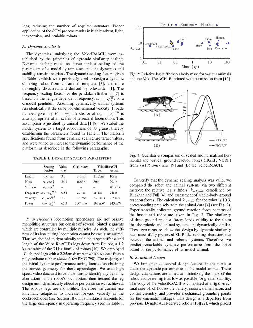
Fig. 2: Relative leg stiffness vs body mass for various animalsand the VelociRoACH. Reprinted with permission from [12].
0 t
GR
F
(A)
(B)VGRFHGRF
Fig. 3: Qualitative comparison of scaled and normalized hor-izontal and vertical ground reaction forces (HGRF, VGRF)from: (A) P. americana [9] and (B) the VelociRoACH.
To verify that the dynamic scaling analysis was valid, wecompared the robot and animal systems via two differentmetrics: the relative leg stiffness, krel,ind, established byBlickhan and Full [4], and assessment of whole-body groundreaction forces. The calculated krel,ind for the robot is 10.3,corresponding precisely with the animal data [4] (see Fig. 2).Experimentally collected ground reaction force patterns ofthe insect and robot are given in Fig. 3. The similarityof these ground reaction forces lends validity to the claimthat the robotic and animal systems are dynamically similar.These two measures show that design by dynamic similarityhas successfully preserved SLIP-like running characteristicsbetween the animal and robotic systems. Therefore, wepredict remarkable dynamic performance from the robotbased on the performance of its model animal.
B. Structural Design
We implemented several design features in the robot toattain the dynamic performance of the model animal. Thesedesign adaptations are aimed at minimizing the mass of therobot, and centering it as low as possible for greater stability.The body of the VelociRoACH is comprised of a rigid struc-tural core which houses the battery, motors, transmission, andcontrol circuitry, and provides mechanical grounding pointsfor the kinematic linkages. This design is a departure fromprevious DynaRoACH-derived robots [13][22], which placed

these components on top of the robot, significantly raisingthe center of gravity. In the present configuration, the motorcasings provide additional stiffness to the core, reducingthe amount of material required for structural integrity. Thekinematic linkages attach to the core of the robot and couplerotary input from the motor to useful leg motions.
C. Kinematic Design
To design the gait kinematics for the VelociRoACH, weconsider the results gleaned from the RHex family of robots.RHex uses a feed-forward clock signal known as the Buehlerclock to prescribe its kinematics [24]. The Buehler clock iscommonly parameterized by four variables: the touchdownand liftoff angles, (ψTD, ψLO) and the stance and flight time,(ts, tf ). For the gait of VelociRoACH, we chose values forthese variables expected to balance speed and stability. P.americana uses a duty factor of β = ts
ts+tf= 0.5 [9], so
we chose the stance and flight durations to be equal. Thetouchdown and liftoff angles were chosen to be symmetricat (ψTD, ψLO) = ±42, as has been used previously [13].To allow for an alternating tripod gait, the fore and aft legsare mechanically constrained 180 out of phase from themiddle leg, as shown in Fig. 4. During straight-line running,we use a software controller (Section II-D) to enforce a 180
offset between the left and right sets of legs such that thecontralateral middle leg of one side steps simultaneously withthe fore and aft legs of the other side. With one actuator perleg, RHex has the ability to adjust its kinematics in software,allowing for highly optimized gaits [26]. The gait kinematicsof VelociRoACH however, are enforced by the geometry ofits kinematic linkages.
Hoover et al. determined the geometry of these linkagesfor the DynaRoACH robot [13], and we used a simi-lar methodology to determine the parameters for the Ve-lociRoACH. When the transmission was bisected down thesaggital plane of the robot to allow for dual-drive actuation,we found that forces on the front and rear legs causedtoo much deflection in the transmission to allow for robustlocomotion performance. Therefore, a planarizing parallelfour-bar linkage was added to each side, as shown in Fig. 4.These linkages minimized the potential energy stored inthe transmission while maximizing its stiffness to off axisloading. They also allowed the reduction of the mass of therecirculating transmission layer by 57%, the movement ofwhich excites parasitic oscillation modes during locomotion.
D. Motor Transmission and Control Electronics
The VelociRoACH uses two 7 mm, 3.3 Ω coreless brushedDC motors (Didel # Mk07-3.3) to drive its legs, with eachside of the robot driven independently. To enable locomotionacross a range a frequencies (4− 24 Hz), we selected a gearratio of 16 : 1.
A lightweight electronics package controls the robot’slocomotion and logs data from its on-board sensors [2]. Itincludes a 40 MHz microprocessor, an inertial measurementunit, an 802.15.4 wireless radio, and motor control circuitry1.
1Embedded board: https://github.com/biomimetics/imageproc pcb
CoM
(A)
(B)
Fig. 4: Views of the kinematic linkages from the side (A)and rear (B).
Fig. 5: Locomotion controller block diagram. The Left PDblock is identical to the Right PD block.
Telemetry data is logged to an on-board flash memory at300 Hz and later downloaded wirelessly to a computer foranalysis. Each motor is equipped with magnetic incrementalencoders. The encoders, along with the motor back EMFsignal, feed a 1 KHz control loop2.
The main locomotion control loop, shown in Fig. 5,consists of two independent control laws. A low gain, pro-portional derivative feedback controller (Right/Left PD) runson each motor to maintain the desired leg frequency. Halleffect encoders and the back EMF signal from the motorsprovide the position and velocity of the motor respectively.In addition to this controller, a synchronizing proportionalintegral (PI) control law enforces the desired phase offsetbetween the motors. The independent control laws provideseveral benefits. At the highest stride frequencies, the motoris speed limited (see Fig. 11) and the control bandwidth is
2Embedded code: https://github.com/biomimetics/octoroach

subsequently reduced. High proportional gain in the syn-chronizing control law ensures that maintaining the phaseoffset between the motors is prioritized and the desired gaitis preferentially maintained. The integral term in the synchro-nizing control law accounts for variations between the twomotors, eliminating the need to characterize each motor. Theindependent control laws also allow the controller’s responseto gait and speed variations to be independently and moreintuitively tuned. The VelociRoACH can also run with thecontrol loop disabled by simply commanding an open loopmotor PWM. At certain PWM duty cycles, the gait willpassively converge to alternating tripod and the robot willrun stably, otherwise open loop performance is unreliable.
III. DYNAMIC PERFORMANCE AND STABILIZATION
P. americana adjusts its limb kinematics to increase speedwhile keeping its stride frequency relatively constant [9].This adaptation allows the animal to operate in a singleresonant regime, which is desirable for effective and robustlocomotion across a range of speeds. Due to the minimallyactuated nature of the VelociRoACH, the kinematics areinvariant. Therefore, we examined the stride frequency de-pendent dynamic response of the robot to find a desirableoperating regime.
Legged locomotion is characterized by periodic trajecto-ries (limit cycles) of the system dynamics. As the scale ofa robot is reduced, the rotational dynamics of the systemhave a larger effect on the motion of the robot: the momentof inertia, I = mr2, scales with α5
L. For a given, size-specific, perturbation we expect a millirobot to rotate farmore than a larger robot. For example: Edubot undergoesroll oscillations of 1 during steady state locomotion [5],whereas the 30 gram VelociRoACH can experience 25 rollrotations during stable locomotion. While some amount ofrotational oscillation can stabilize the system [5], limit cycleswith high rotational energy–coupled with low inertia–canincrease the chance of a disturbance causing catastrophicfailure. We therefore focused our dynamic tuning effortson finding highly robust, passively stable limit cycles withminimal rotational energy.
A. Roll Stabilizer
During steady state running, the VelociRoACH has signif-icant roll oscillations, as shown in Fig. 6. These oscillationsarise as a dynamic effect due to alternating tripod kinematicswherein one side of the robot has twice the effective stiffnessas the other [5]. To reduce the roll oscillations, we add anaerodynamic stabilizer consisting of two rectangular sections,measuring 5cm x 4cm, of 50 µm PET oriented parallel tothe direction of forward travel. These airfoils are rigidlyconstrained by a carbon fiber frame at a distance of 15cmfrom the center of the robot (see Fig. 1). As a control betweenthe inertial and aerodynamic effects, we also examine theperformance of the stabilizer with the PET airfoils removed.The aerodynamic stabilizer is specifically designed to damproll oscillations, while being lightweight and having minimaldrag in the forward direction. A significant aerodynamic
4With Stabilizer Without Stabilizer
6
8
10
12
14
16
18
20
22
0 30 60 90 120Roll Frequency (Hz)
24
0 30 60 90 120Pitch Frequency (Hz)
StrideFrequency(Hz)
Fig. 6: Frequency spectra of the robot’s oscillations withand without the aerodynamic stabilizer plotted as a functionof the commanded stride frequency. Oscillatory energy inthe roll axis was the highest of all the rotational compo-nents prior to the addition of the stabilizer. The stabilizereffectively filters this energy at higher stride frequencies.Yaw oscillations (not shown) are relatively unaffected by thestabilizer and have a peak magnitude of 904 /s.
force results when the robot rolls during high-speed runningdue to the high drag nature of a flat plate. We computedthe differing inertias of the robot with and without the rollstabilizer using a CAD model of the robot and verified themin part using rigid body pendulum experiments. The form ofthe inertia tensors is given in (1), where x, y and z are theroll, pitch, and yaw axes, respectively. The standard robothas inertia, I0 (2); IS (3) corresponds to the robot with thestabilizer.
I =
Ixx Ixy IxzIyx Iyy IyzIzx Izy Izz
kg mm2 (1)

I0 =
9.29 −0.12 −0.22−0.12 21.51 0.007−0.22 0.007 21.97
kg mm2 (2)
IS =
28.52 −0.12 −0.23−0.12 23.12 0.005−0.23 0.005 45.92
kg mm2 (3)
B. Steady State Running
Telemetry data was captured for the VelociRoACH run-ning on closed-loop carpet at stride frequencies in the4 − 25 Hz range. In particular, tri-axial gyroscope data waslogged at 300 Hz during each run (repeated three times). Wediscarded the leading one second of each trial to removeany transient effects. To better understand the nature ofthe VelociRoACH oscillations as a function of the stridefrequency, we used Python3 to compute the fast Fouriertransform of each run, first passed through a Hann window,and then averaged across repeated trials. The resulting fre-quency spectra are plotted for pitch and roll in Fig. 6. Rollshows a large degree of oscillation without the stabilizer,visible throughout the spectra and reaching up to the fifthharmonic of the commanded stride frequency. This motivatedthe addition of the stabilizer on the roll axis, and Fig. 6shows this approach was successful at reducing the degreeof roll oscillations. Both pitch and yaw, which have lessoscillations to begin with, are relatively unaffected by theadded stabilizer.
We analyzed the gyroscope data to determine the amountof rotational energy the robot possesses in each stable limitcycle. To find the energy, we first parameterize the data bythe accumulated stride phase, φ, which is the total angularrotation of the output link from the beginning of the trial. Therotational energy is calculated using the angular velocitiesmeasured from the on board gyroscope with
ERot(φ) =1
2ω(φ)T Iω(φ). (4)
The energy is then divided into individual strides
EnRot(φ) = ERot(φ) : 2π(n− 1) ≤ φ < 2πn, (5)
where n represents the stride number. The average andvariance among k = 10 successive strides is then computedfrom
ERot(φ) =1
k
k∑n=1
EnRot(φ) (6)
and
σ(ERot(φ))2 =1
k − 1
k∑n=1
(EnRot(φ) − ERot(φ))2. (7)
As a metric of performance, we define the mean rotationalenergy during a stride to be
ERot =1
2π
∫ 2π
0
ERot(φ) dφ. (8)
3Scientific Tools for Python: http://www.scipy.org/
0
0.1
0.2
0.3
0.4
ER
ot(m
J)
5 10 15 20 250
0.05
0.1
0.15
0.2
Stride Frequency (Hz)
σ(E
Rot)2
(mJ
)
Without Stabilizer With Stabilizer Inertial Control
Fig. 7: Lowest energy limit cycle for each treatment [Top]and average variation in the rotational energy over the courseof a stride [Bottom].
An additional metric, the mean normalized variance in en-ergy over a stride is given by
σ(ERot)2 =1
2π
∫ 2π
0
[σ(ERot(φ))2/ERot(φ)] dφ. (9)
Fig. 7 shows the effect of both the aerodynamic stabilizerand the inertial control configuration on the system. At lowfrequencies, the higher inertias of the aerodynamic stabilizerand the inertial control increase the total energy. A localminimum in average frequency is found for the unmodifiedand inertial control case at 16 Hz, near the dynamicallyscaled frequency of the robot (see Table I). By contrast,with the aerodynamic stabilizer equipped, the range of fre-quencies with low energy limit cycles is increased, reducingthe robot’s reliance on a single well-tuned frequency. Weobserve a clear decrease in the average energy over allfrequencies ≥ 10 Hz for the aerodynamically stabilized robotwhen compared to the unmodified and inertial control cases.We also consider the robot’s ability to passively maintainstable limit cycles while running in the presence of smallperturbations, such as foot slip and ground contact variations.The variation in energy between successive strides shown inFig. 7 provides a measure of the periodicity of locomotionand of how robust the limit cycle is to small disturbances.Both the aerodynamic stabilizer and the inertial control showless variation in response to small perturbations. By contrast,the unmodified robot shows generally higher variation, andsignificantly higher variation at some frequencies. The lowerinertia of the unmodified robot increases its susceptibilityto small disturbances and correspondingly decreases thestability margin of the robot.
C. Disturbance Rejection
In addition to increasing robustness to small perturbations,we hypothesized that the aerodynamic damper would allowthe robot to recover more quickly from large perturbations.

TABLE II: AVERAGE DISTURBANCE RESPONSE
Stridefrequency
Configuration
Without Stabilizer With Stabilizer
16 HzTs 0.37 s 0.18 s
EDisturb 1.15 mJ 0.37 mJSDisturb 435 µJ · s 66 µJ · s
20 HzTs 0.29 s 0.24 s
EDisturb 1.97 mJ 0.74 mJSDisturb 578 µJ · s 186 µJ · s
To assess the validity of this hypothesis, we ran the robotover a known obstacle, in this case a vertical step equalto 35% of its hip height. We measured the departure ofbody-centric metrics away from the median state and theirsubsequent recovery. The robot is more prone to locomotionfailures due to excessive body rotation so we chose the body-centric parameter to be the rotational energy in the system.This was chosen over any individual component of rotationbecause the specific response of the robot is highly sensitiveto when in the stride the disturbance was encountered, therobot’s stride frequency, and whether or not the aerodynamicstabilizer was equipped. Therefore, the rotational energy ofthe system is a more robust indicator of the perturbed stateof the robot. To account for the variations in the rotationalenergy due to the periodic motion of the robot, a movingaverage filter was applied with a window size equal to thelength of a single stride. We selected the settling time ofthe robot, Ts, as a disturbance rejection metric. The settlingtime is defined as the time that 80% of the maximum energyincrease due to the disturbance takes to dissipate. We alsocalculated the average increase in rotational energy from theperturbation,
EDisturb =1
Ts
∫ t0+Ts
t0
(E(t) − Esteadystate) dt, (10)
and the action of the disturbance,
SDisturb = Ts · EDisturb (11)
as additional figures of merit.Representative step responses of the robot running at 16
Hz with and without the stabilizer are shown in Fig. 8a and8b. The robot encounters the step at time t0 and the transientresponse duration is shaded in gray. Table II summarizes theresults of the disturbance rejection experiments (N≥3). Therobot equipped with stabilizer shows increased performanceacross all metrics at both stride frequencies tested. Alongwith rejecting the disturbance more quickly, the aerodynamicstabilizer also reduced the amount of energy injected into thesystem by the disturbance. The action of the disturbance isreduced by a factor of six at 16 Hz and a factor of threeat 20 Hz, demonstrating the success of the aerodynamicallystabilized robot at initially rejecting and quickly recoveringfrom the disturbance.
IV. RESULTS
Fig. 9 shows the speed of the robot as a function ofcommanded stride frequency. The aerodynamic stabilizer
0 0.2 t0 0.4 0.6 0.8 10
5
10
ER
ot(m
J)
Time (s)
ERot Average ERot
Ts
(a) Without Stabilizer
0 0.2 t0 0.4 0.6 0.8 10
5
10
ER
ot(m
J)
Time (s)
0.2 0.4 0.60
0.5
1
Ts
(b) With Stabilizer
Fig. 8: Representative energetic disturbance and stabilizationresponse to a step perturbation while running at 16 Hz. Theaverage energy is computed using a moving average filterwith a window size equivalent to the length of a single stride.Ts represents the duration of the transient response, whichis shaded in gray.
4 8 12 16 20 24Stride Frequency (Hz)
0.0
0.5
1.0
1.5
2.0
2.5
3.0
Sp
eed
(m/s
)
Without Stabilizer With Stabilizer
Fig. 9: Robot speed with and without roll stabilizers as afunction of the commanded stride frequency.
improved the robot’s reliability at the higher speeds, withzero incidents of catastrophic destabilization, which wereoccasionally observed in the unmodified configuration. Thereis no measurable effect from the stabilizers on the forwardprogress of the robot. The addition of the roll stabilizerdid not slow the robot, as might have been expected fromadditional aerodynamic drag.
In addition to measuring the speed of the VelociRoACH,we calculated the specific resistance, SR = P
mgv (see Fig.10), which is the power required per Newton of robot per m/sof velocity. As stride frequency increases, we see an initialnegative trend followed by a nearly constant region and then
5 10 15 20 2502468
10
Stride Frequency (Hz)
Spec
ific
Res
istan
ceWithout Stabilizers With Stabilizers
Fig. 10: Specific Resistance as a function of stride frequency.
5 10 15 20 250
0.5
1
Cur
rent
(A
)
5 10 15 20 250
2
4V
olta
ge (
V)
5 10 15 20 250
0.5
1
Mot
or P
ower
(W
)
Stride Frequency (Hz)
Without Stabilizer With Stabilizer
Fig. 11: Individual motor performance as a function ofstride frequency. These curves are representative of a lightlyloaded, speed-limited motor.
a sharp reduction as the motor reaches the terminus of itsspeed limited regime.
Fig. 11 shows the voltage, current, and power of the mo-tors across the frequencies of operation. Due to the efficientflexure-based transmission and energy storage and returnfrom the compliant legs, very little torque (and thus current)is needed to drive the legs at the highest frequencies. Fromwork-loop experiments performed using a muscle lever, wefound that only 15 µJ were dissipated per leg compression.This leads to highly efficient high-speed running, as seenfrom the drop in motor power at high speeds. These motordynamics lead to the unintuitive result that the robot uses theleast amount of power when operating at its maximum speed.A sufficient condition for this scenario is that the motor beas minimally loaded as possible, which is achievable at themillirobotic scale with proper mechanical design and welltuned dynamics.
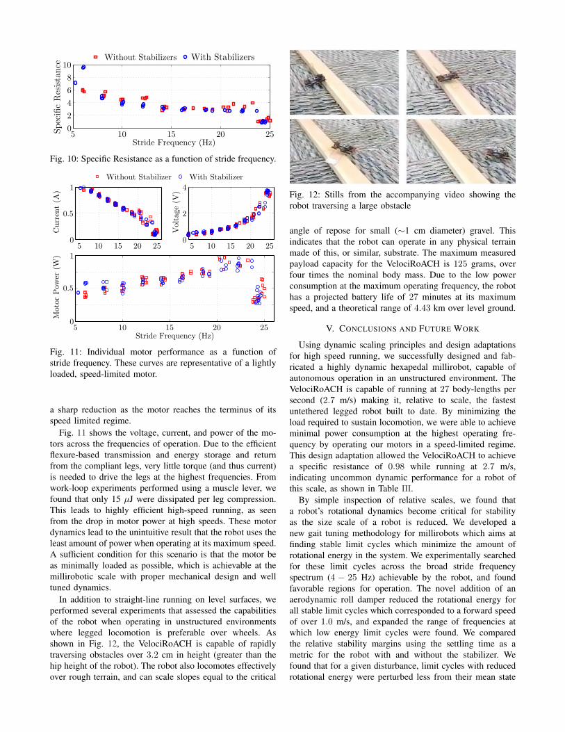
In addition to straight-line running on level surfaces, weperformed several experiments that assessed the capabilitiesof the robot when operating in unstructured environmentswhere legged locomotion is preferable over wheels. Asshown in Fig. 12, the VelociRoACH is capable of rapidlytraversing obstacles over 3.2 cm in height (greater than thehip height of the robot). The robot also locomotes effectivelyover rough terrain, and can scale slopes equal to the critical
Fig. 12: Stills from the accompanying video showing therobot traversing a large obstacle
angle of repose for small (∼1 cm diameter) gravel. Thisindicates that the robot can operate in any physical terrainmade of this, or similar, substrate. The maximum measuredpayload capacity for the VelociRoACH is 125 grams, overfour times the nominal body mass. Due to the low powerconsumption at the maximum operating frequency, the robothas a projected battery life of 27 minutes at its maximumspeed, and a theoretical range of 4.43 km over level ground.
V. CONCLUSIONS AND FUTURE WORK
Using dynamic scaling principles and design adaptationsfor high speed running, we successfully designed and fab-ricated a highly dynamic hexapedal millirobot, capable ofautonomous operation in an unstructured environment. TheVelociRoACH is capable of running at 27 body-lengths persecond (2.7 m/s) making it, relative to scale, the fastestuntethered legged robot built to date. By minimizing theload required to sustain locomotion, we were able to achieveminimal power consumption at the highest operating fre-quency by operating our motors in a speed-limited regime.This design adaptation allowed the VelociRoACH to achievea specific resistance of 0.98 while running at 2.7 m/s,indicating uncommon dynamic performance for a robot ofthis scale, as shown in Table III.
By simple inspection of relative scales, we found thata robot’s rotational dynamics become critical for stabilityas the size scale of a robot is reduced. We developed anew gait tuning methodology for millirobots which aims atfinding stable limit cycles which minimize the amount ofrotational energy in the system. We experimentally searchedfor these limit cycles across the broad stride frequencyspectrum (4 − 25 Hz) achievable by the robot, and foundfavorable regions for operation. The novel addition of anaerodynamic roll damper reduced the rotational energy forall stable limit cycles which corresponded to a forward speedof over 1.0 m/s, and expanded the range of frequencies atwhich low energy limit cycles were found. We comparedthe relative stability margins using the settling time as ametric for the robot with and without the stabilizer. Wefound that for a given disturbance, limit cycles with reducedrotational energy were perturbed less from their mean state

TABLE III: COMPARISON TO SIMILAR ROBOTS
VelociRoACH DynaRoACH [13] DASH [3] iSprawl [17] Research RHex [26]
External Dimensions (LxWxH) (cm) 10 x 6.5 x 4.2 10 x 4.5 x 3 10 x 5 x 10 15.5 x 11.6 x 0.7 54 x 39 x 12Mass (g) 29.1 23.7 16.2 300 8200Top Speed (body-lengths/second)–(m/s) 27 (2.7) 14 (1.4) 15 (1.5) 15 (2.3) 5 (2.7)Stride Frequency (Hz) 24 20 17 14 6Specific Resistance 0.98 1.1 1.42 1.75 0.72
and recovered more quickly. These results demonstrate thevalidity of our new dynamic tuning approach for milliroboticlocomotion. We therefore conclude that aerodynamic loco-motion adaptations can aid small scale robots operating inunstructured environments.
Although the VelociRoACH is fully capable of effectivelocomotion at high speeds, we found that the addition ofan aerodynamic stabilizer increased its capacity to rejectenvironmental disturbances. Future work should accuratelymodel the aerodynamic effect the dampers produce, and usethat information to optimize their geometry for both forwardvelocity and stability. The large size of the stabilizer ad-versely effects the robot’s mobility in cluttered environments,so it would be valuable to explore other potentially collapsi-ble wing configurations. An in-depth statistical analysis onan extensive set of data will be used to formally determinethe effect of the stabilizer on the variability of the robot’sperformance.
ACKNOWLEDGMENTS
The authors would like to thank the Center for IntegrativeBiomechanics in Education and Research for allowing theuse of their force platform and muscle lever to performexperiments. Thanks also to the members of the BiomimeticMillisystems Lab for their helpful comments and discussions.
REFERENCES
[1] R. M. Alexander, Principles of Animal Locomotion. PrincetonUniversity Press, 2003.
[2] S. S. Baek, F. L. Garcia Bermudez, and R. S. Fearing, “Flight controlfor target seeking by 13 gram ornithopter,” 2011 IEEE/RSJ Int. Conf.on Intelligent Robots and Systems, pp. 2674–2681, Sept. 2011.
[3] P. Birkmeyer, K. Peterson, and R. S. Fearing, “DASH : A dynamic16g hexapedal robot,” Int.Conf. on Intelligent Robots and Systems, pp.2683–2689, 2009.
[4] R. Blickhan and R. J. Full, “Similarity in multilegged locomotion:Bouncing like a monopode,” Jnl. of Comparative Physiology A:Neuroethology, Sensory, Neural, and Behavioral Physiology, vol. 173,no. 5, pp. 509–517, 1993.
[5] S. Burden, J. E. Clark, J. D. Weingarten, H. Komsuoglu, and D. E.Koditschek, “Heterogeneous Leg Stiffness and Roll in Dynamic Run-ning,” IEEE Int.Conf. on Robotics and Automation, pp. 4645–4652,Apr. 2007.
[6] J. E. Clark and M. R. Cutkosky, “Stability measure comparison for thedesign of a dynamic running robot,” Climbing and Walking Robots,vol. 4, pp. 261–268, 2006.
[7] J. E. Clark, D. I. Goldman, P.-c. Lin, G. a. Lynch, T. S. Chen,H. Komsuoglu, R. J. Full, and D. E. Koditschek, “Design of a bio-inspired dynamical vertical climbing robot,” Robotics: Science andSystems, 2007.
[8] C. T. Farley, J. Glasheen, and T. A. McMahon, “Running springs:speed and animal size.” Jnl. of Experimental Biology, vol. 185, pp.71–86, Dec. 1993.
[9] R. J. Full and M. S. Tu, “Mechanics of a rapid running insect: two-,four- and six-legged locomotion.” Jnl. of Experimental Biology, vol.156, pp. 215–31, Mar. 1991.
[10] K. C. Galloway, J. E. Clark, M. Yim, and D. E. Koditschek, “Experi-mental Investigations into the Role of Passive Variable Compliant Legsfor Dynamic Robotic Locomotion,” in IEEE Int. Conf. on Robotics andAutomation, 2011, pp. 1243–1249.
[11] D. I. Goldman, T. S. Chen, D. M. Dudek, and R. J. Full, “Dynamics ofrapid vertical climbing in cockroaches reveals a template.” The Journalof Experimental Biology, vol. 209, pp. 2990–3000, Aug. 2006.
[12] P. Holmes, R. J. Full, D. Koditschek, and J. Guckenheimer, “TheDynamics of Legged Locomotion: Models, Analyses, and Challenges,”SIAM Review, vol. 48, no. 2, pp. 207–304, Jan. 2006.
[13] A. M. Hoover, S. Burden, X. Y. Fu, S. S. Sastry, and R. S. Fearing,“Bio-inspired design and dynamic maneuverability of a minimallyactuated six-legged robot,” in 3rd IEEE RAS and EMBS Int. Conf.on Biomedical Robotics and Biomechatronics (BioRob), Sept. 2010,pp. 869–876.
[14] A. M. Hoover and R. S. Fearing, “Fast scale prototyping for foldedmillirobots,” IEEE Int. Conf. on Robotics and Automation, pp. 886–892, 2008.
[15] K. Jayaram, J. M. Mongeau, B. McRae, and R. J. Full, “High-speedhorizontal to vertical transitions in running cockroaches reveals aprinciple of robustness,” in Society for Integrative and ComparativeBiology, 2010.
[16] D. L. Jindrich and R. J. Full, “Dynamic stabilization of rapid hexapedallocomotion.” Jnl. of Experimental Biology, vol. 205, pp. 2803–23,Sept. 2002.
[17] S. Kim, J. E. Clark, and M. R. Cutkosky, “iSprawl: Design and Tuningfor High-speed Autonomous Open-loop Running,” The Int. Jnl. ofRobotics Research, vol. 25, no. 9, pp. 903–912, Sept. 2006.
[18] A. Krogh, “The Progress of Physiology,” The American Journal ofPhysiology, pp. pp. 243–251, 1929.
[19] J.-M. Mongeau, B. McRae, A. Jusufi, P. Birkmeyer, A. M. Hoover,R. S. Fearing, and R. J. Full, “Rapid inversion: running animals androbots swing like a pendulum under ledges.” PloS one, vol. 7, no. 6,p. e38003, Jan. 2012.
[20] K. Peterson, P. Birkmeyer, R. Dudley, and R. S. Fearing, “A wing-assisted running robot and implications for avian flight evolution,”Bioinspiration & Biomimetics, vol. 6, no. 4, p. 46008, 2011.
[21] K. Peterson and R. S. Fearing, “Experimental dynamics of wingassisted running for a bipedal ornithopter,” in IEEE Int. Conf. onIntelligent Robots and Systems, 2011, pp. 5080–5086.
[22] A. Pullin, N. Kohut, D. Zarrouk, and R. S. Fearing, “Dynamic turningof 13 cm robot comparing tail and differential drive,” IEEE Int. Conf.on Robotics and Automation, 2012.
[23] U. Saranli, M. Buehler, and D. E. Koditschek, “RHex: A Simple andHighly Mobile Hexapod Robot,” The International Journal of RoboticsResearch, vol. 20, no. 7, pp. 616–631, July 2001.
[24] J. E. Seipel and P. J. Holmes, “A simple model for clock-actuatedlegged locomotion,” Regular and Chaotic Dynamics, vol. 12, no. 5,pp. 502–520, Oct. 2007.
[25] S. Sponberg and R. J. Full, “Neuromechanical response of musculo-skeletal structures in cockroaches during rapid running on roughterrain.” Jnl. of Experimental Biology, vol. 211, pp. 433–46, Feb. 2008.
[26] J. D. Weingarten, G. A. D. Lopes, M. Buehler, R. E. Groff, and D. E.Koditschek, “Automated Gait Adaptation for Legged Robots,” IEEEInt. Conf. on Robotics and Automation, 2004.