antenna theory and design slides 1
TRANSCRIPT

7/29/2019 Antenna Theory and Design Slides 1
http://slidepdf.com/reader/full/antenna-theory-and-design-slides-1 1/86
ANTENNA THEORY AND DESIGN
FALL 2013
Instructor: Veysel Demir
Antenna Fundamentals and
Definitions

7/29/2019 Antenna Theory and Design Slides 1
http://slidepdf.com/reader/full/antenna-theory-and-design-slides-1 2/86
9/13/2013 Prepared by Dr. Veysel Demir, EE, NIU 2
Electromagnetic Waves
Electromagnetic waves in space are the basis of radio
transmission over great distances without direct wire connection
between the transmitting and receiving points.
At the transmitting and receiving stations, radio signals exist in
the form of high-frequency alternating currents in conductors
and in electronic amplifying devices.
Between the transmitter and receiver they exist as
electromagnetic waves in space.
Antennas are the devices that act as go-betweens.
7/29/2019 Antenna Theory and Design Slides 1
http://slidepdf.com/reader/full/antenna-theory-and-design-slides-1 3/86
9/13/2013 Prepared by Dr. Veysel Demir, EE, NIU 3
Transmitter and Receiver
Transmitter :
The antenna converts the energy of the electrical currentsinto the form of an electromagnetic field.
It ―launches‖ the waves into space.
Receiver :
The antenna captures energy from the arriving field, and it
converts the field variations into current and voltage replicasof those at the transmitter
The voltages and currents are much smaller in amplitude -
need to use amplifiers.

7/29/2019 Antenna Theory and Design Slides 1
http://slidepdf.com/reader/full/antenna-theory-and-design-slides-1 4/86
9/13/2013 Prepared by Dr. Veysel Demir, EE, NIU 4
Characteristics of Electromagnetic Waves
A wave is an oscillatory motion of any kind.
Electromagnetic waves are electric and magnetic field variations
All waves are characterized by the property called propagation.
Waves travel at characteristic speeds
depending on the type of wave and the nature of the propagation
medium
In free space electromagnetic waves travel
In other propagation media their speed is less:
8
3 10 /c m s
r r
cv

7/29/2019 Antenna Theory and Design Slides 1
http://slidepdf.com/reader/full/antenna-theory-and-design-slides-1 5/86
9/13/2013 Prepared by Dr. Veysel Demir, EE, NIU 5
Characteristics of Electromagnetic Waves
Electromagnetic waves may not travel through somemedium. At very low radio frequencies radio waves cannot penetrate
the ionosphere; they are reflected from it.
At very high frequencies waves pass through the ionosphereunimpeded.
The atmospheric layer bounded by the ionosphere at the topand Earth’s surface at the bottom forms a guiding structurefor the propagation of radio waves in the HF band.
Atmosphere as guiding structure for radio waves.

7/29/2019 Antenna Theory and Design Slides 1
http://slidepdf.com/reader/full/antenna-theory-and-design-slides-1 6/86
9/13/2013 Prepared by Dr. Veysel Demir, EE, NIU 6
Frequency and Wavelength
The oscillations of waves are periodic
They are characterized by a frequency The frequency is expressed in Hertz (Hz)
Complex waves may contain more than one frequency.
A single-frequency wave motion has the form of a sinusoid.
0
2 2( , ) cos
t x y x t A
T
magnitude time period spatial wavelength reference phase
v
f

7/29/2019 Antenna Theory and Design Slides 1
http://slidepdf.com/reader/full/antenna-theory-and-design-slides-1 7/869/13/2013 Prepared by Dr. Veysel Demir, EE, NIU 7
Sinusoidal Wave in Lossless Medium
0
2 20 ( , ) cos
t x y x t A
T

7/29/2019 Antenna Theory and Design Slides 1
http://slidepdf.com/reader/full/antenna-theory-and-design-slides-1 8/869/13/2013 Prepared by Dr. Veysel Demir, EE, NIU 8
Frequency Spectrum
7/29/2019 Antenna Theory and Design Slides 1
http://slidepdf.com/reader/full/antenna-theory-and-design-slides-1 9/869/13/2013 Prepared by Dr. Veysel Demir, EE, NIU 9
Frequency Spectrum
The electromagnetic spectrum covers an enormous range of
frequencies including cosmic-ray radiation with frequencies in excess of 1020 Hz.
The International Telecommunications Union (ITU), an
organization of the United Nations, makes the general guidelines
for the assignment and use of frequencies.
For the United States,
federal governmental usages coordinated by the National
Telecommunications and Information Agency (NTIA)
nonfederal governmental frequency usages coordinated by Federal
Communications Commission (FCC)

7/29/2019 Antenna Theory and Design Slides 1
http://slidepdf.com/reader/full/antenna-theory-and-design-slides-1 10/869/13/2013 Prepared by Dr. Veysel Demir, EE, NIU 10
The Radio Frequency Spectrum

7/29/2019 Antenna Theory and Design Slides 1
http://slidepdf.com/reader/full/antenna-theory-and-design-slides-1 11/869/13/2013 Prepared by Dr. Veysel Demir, EE, NIU 11
Standard Radar Band Designations

7/29/2019 Antenna Theory and Design Slides 1
http://slidepdf.com/reader/full/antenna-theory-and-design-slides-1 12/869/13/2013 Prepared by Dr. Veysel Demir, EE, NIU 12
Frequency Allocations
Some of the better-known frequency allocations within the United States include:
AM (amplitude modulation) broadcast: 535 –1705 kHz
FM (frequency modulation) broadcast: 88 –108 MHz
Television in 6 MHz bandwidth numbered channels: 2 –6, 54 –60 MHz, . . . , 82 –88 MHz
7 –13, 174 –180 MHz, . . . , 210 –216 MHz 14 –36, 470 –476 MHz, . . . , 600 –608 MHz
Note: 614 –698 MHz (without channel numbers) is allocated to TV. The frequencies608 –806 MHz were previously allocated for TV channels 37 –69.
GPS (global positioning satellite): 1227.6 MHz (military); 1575.42 MHz and1227.6 (civilian);Telemetry on 2227.5 MHz
GSM-850: uplink 824 –849 MHz, downlink 869 –894 MHz
GSM-1900: uplink 1850 –1910 MHz, downlink 1930 –1990 MHz
ISM (industrial, scientific and medical) 902 –928 MHz, 2.4 –2.5 GHz, 5.725 –5.875GHz

7/29/2019 Antenna Theory and Design Slides 1
http://slidepdf.com/reader/full/antenna-theory-and-design-slides-1 13/869/13/2013 Prepared by Dr. Veysel Demir, EE, NIU 13
Plane Waves
Waves radiated by an EM source, such as an antenna,
have spherical wavefronts as in (a); to a distant observer, however, the wavefront across the observer’s
aperture appears approximately planar as in (b).

7/29/2019 Antenna Theory and Design Slides 1
http://slidepdf.com/reader/full/antenna-theory-and-design-slides-1 14/869/13/2013 Prepared by Dr. Veysel Demir, EE, NIU 14
Uniform Plane Waves
The electric and magnetic fields are perpendicular to each other
and both are perpendicular to direction of propagation.
These directional properties characterize a transverse
electromagnetic wave.
A transverse electromagnetic (TEM) wave
0 2 2( , ) cos x t z E z t E T
0
2 2( , ) cos y
t z H z t H
T
0 0 0 E H H
0
377 In free space:

7/29/2019 Antenna Theory and Design Slides 1
http://slidepdf.com/reader/full/antenna-theory-and-design-slides-1 15/869/13/2013 Prepared by Dr. Veysel Demir, EE, NIU 15
Uniform Plane Waves
Spatial variations of E and H.
7/29/2019 Antenna Theory and Design Slides 1
http://slidepdf.com/reader/full/antenna-theory-and-design-slides-1 16/869/13/2013 Prepared by Dr. Veysel Demir, EE, NIU 16
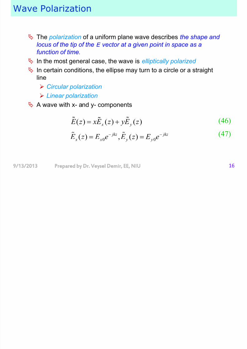
Wave Polarization
The polarization of a uniform plane wave describes the shape and locus of the tip of the E vector at a given point in space as a
function of time.
In the most general case, the wave is elliptically polarized
In certain conditions, the ellipse may turn to a circle or a straight
line Circular polarization
Linear polarization
A wave with x- and y- components
ˆ ˆ( ) ( ) ( ) x y E z xE z yE z (46)
0 0( ) , ( ) jkz jkz
x x y y E z E e E z E e (47)
7/29/2019 Antenna Theory and Design Slides 1
http://slidepdf.com/reader/full/antenna-theory-and-design-slides-1 17/869/13/2013 Prepared by Dr. Veysel Demir, EE, NIU 17
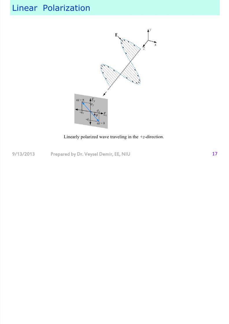
Linear Polarization
Linearly polarized wave traveling in the +z -direction.

7/29/2019 Antenna Theory and Design Slides 1
http://slidepdf.com/reader/full/antenna-theory-and-design-slides-1 18/869/13/2013 Prepared by Dr. Veysel Demir, EE, NIU 18
Right-Hand Circular (RHC) Polarization
Right-hand circularly polarized wave radiated by a helical antenna.

7/29/2019 Antenna Theory and Design Slides 1
http://slidepdf.com/reader/full/antenna-theory-and-design-slides-1 19/869/13/2013 Prepared by Dr. Veysel Demir, EE, NIU 19
Circular Polarization
Polarization handedness is defined in terms of rotation of
E
as afunction of time in a fixed plane orthogonal to the direction of
propagation
Circularly polarized plane waves propagating in the +z -direction

7/29/2019 Antenna Theory and Design Slides 1
http://slidepdf.com/reader/full/antenna-theory-and-design-slides-1 20/869/13/2013 Prepared by Dr. Veysel Demir, EE, NIU 20
Polarization
The polarization is random when there is no fixed polarization or pattern of polarization variation an effect present in light waves emitted from an incandescent source (e.g.,
the sun or an electric light bulb).
It is seldom observed in man made radio emissions.
Such would result if two independently random sources of radio noise
are connected to right-angle-polarized elements of a single antenna. E.g. used in radio and radar military countermeasures, or ―jamming‖
Linear polarization is the most commonly employed by far.
One application for circular polarization is in communications betweenearth and space, to mitigate the effects of polarization rotation causedby the ionosphere

7/29/2019 Antenna Theory and Design Slides 1
http://slidepdf.com/reader/full/antenna-theory-and-design-slides-1 21/869/13/2013 Prepared by Dr. Veysel Demir, EE, NIU 21
Spherical Waves and the Inverse-Square Law
An electromagnetic wave represents a flow of energy in the direction of
propagation.
The power density of the wave:
The rate at which energy flows through a unit area of surface in space
Energy per unit time per unit of area: watts per square meter.
The average power density of the wave is the time average value of S
2( / ) ( )the poynting veS E H m r W cto
* 21Re ( / )
2
avS E H W m
, : instantaneousfields
, : phasor fields
E H
E H

7/29/2019 Antenna Theory and Design Slides 1
http://slidepdf.com/reader/full/antenna-theory-and-design-slides-1 22/869/13/2013 Prepared by Dr. Veysel Demir, EE, NIU 22
Spherical Waves and the Inverse-Square Law
Isotropic radiator:
The source radiates power at a constant rate uniformly in alldirections,
The total power flowing through any spherical surface centered at the
source will be uniformly distributed over the surface and must equal the
total power radiated.
24
t R
P S
R P t = total power
S R = power density at a distance R
R
RS

7/29/2019 Antenna Theory and Design Slides 1
http://slidepdf.com/reader/full/antenna-theory-and-design-slides-1 23/869/13/2013 Prepared by Dr. Veysel Demir, EE, NIU 23
The Inverse-Square Law
A R
B R
2 2,
4 4 A B
t t R R
A B
P P S S
R R
2
A
B
R B
R A
S R
S R
The power density is inversely proportional to the square
of the distance from the source.
However, this is true only within the far field of an antenna,
because an antenna is of finite size andtherefore it is not located solely at apoint.
The far field exists beyond a minimumseparation distance of an antenna, whichdepends on antenna dimensions andwavelength.
A RS
B RS

7/29/2019 Antenna Theory and Design Slides 1
http://slidepdf.com/reader/full/antenna-theory-and-design-slides-1 24/869/13/2013 Prepared by Dr. Veysel Demir, EE, NIU 24
Decibel (Logarithmic) Expression of Attenuation
Wave attenuation is expressed also in terms of the logarithms of
the power-density or electric-intensity ratios, an alternative method widely used in describing signal amplificationor attenuation in telephone and radio systems.
11 1
2 2 2
10log 10log 20log ( ) E P P
G G dB G dB
P P E
Attenuation due to the spherical spreading
of the wave—that is, as expressed by theinverse-square law—is sometimes calledthe space attenuation of the wave.

7/29/2019 Antenna Theory and Design Slides 1
http://slidepdf.com/reader/full/antenna-theory-and-design-slides-1 25/86
9/13/2013 Prepared by Dr. Veysel Demir, EE, NIU 25
Absorption
There may sometimes be attenuation due to absorption of power by the
propagation medium.
This does not occur in a vacuum, but it will occur in a medium thatcontains material particles that interact with the waves.
At some frequencies, for example, certain gases of the earth’s
atmosphere (oxygen and water vapor) cause absorption. This occursslightly in the VHF region and becomes significant over longtransmission paths in the UHF region and above.
Unlike space attenuation, attenuation due to absorption does notdepend on the distance from the source but only on the total distance
traveled by the wave.

7/29/2019 Antenna Theory and Design Slides 1
http://slidepdf.com/reader/full/antenna-theory-and-design-slides-1 26/86
9/13/2013 Prepared by Dr. Veysel Demir, EE, NIU 26
Absorption
Certain materials are capable of absorbing radio waves verystrongly.
Waves traveling in these materials will be attenuated greatly withina short distance, of the order of centimeters or meters.
Sometimes such materials are used in antenna design tosuppress radiation in undesired directions, or to prevent―leakage‖ of waves from one part of an antenna to another
where they would have an undesirable effect.
An anechoic chamber
b
7/29/2019 Antenna Theory and Design Slides 1
http://slidepdf.com/reader/full/antenna-theory-and-design-slides-1 27/86
9/13/2013 Prepared by Dr. Veysel Demir, EE, NIU 27
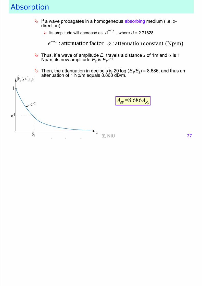
Absorption
If a wave propagates in a homogeneous absorbing medium (i.e. x-direction),
its amplitude will decrease as , where e = 2.71828
Thus, if a wave of amplitude E 1 travels a distance x of 1m and is 1Np/m, its new amplitude E 2 is E 1e
−1.
Then, the attenuation in decibels is 20 log (E 1/E 2) = 8.686, and thus anattenuation of 1 Np/m equals 8.868 dB/m.
x
e
: attenuationfactor xe
: attenuationconstant (Np/m)
=8.686dB Np A A
H di

7/29/2019 Antenna Theory and Design Slides 1
http://slidepdf.com/reader/full/antenna-theory-and-design-slides-1 28/86
9/13/2013 Prepared by Dr. Veysel Demir, EE, NIU 28Prepared by Dr. Veysel Demir, EE, NIU
How antennas radiate
Electromagnetic ―news‖ propagate with speed of light
An isolated charge induces an electric field at every point
in space.
This field is called the ―Coulombian‖ field
: permittivity of
the medium
: radiusof circle, :speedof light, : timer c t
r ct
R di ti f h

7/29/2019 Antenna Theory and Design Slides 1
http://slidepdf.com/reader/full/antenna-theory-and-design-slides-1 29/86
9/13/2013 Prepared by Dr. Veysel Demir, EE, NIU 29
Radiation from a charge
If the charge is moving with a constant speed, the fields move
together with the charge
If the charge is accelerated, then the charge produces a
―disturbance‖ of the fields.
This ―disturbance‖ propagates and this propagation is called
radiation.
Direction of movement
Charge moves with constant velocity
until reaching A
Charge is accelerated between A
and B for seconds
Field lines after t seconds shall be
continuous
t
Field lines generated by the
charge when it was at A, andobserved after t seconds
Field lines generated by the
charge when it was at B, and
observed after secondst t
A B
R di ti f h
7/29/2019 Antenna Theory and Design Slides 1
http://slidepdf.com/reader/full/antenna-theory-and-design-slides-1 30/86
9/13/2013 Prepared by Dr. Veysel Demir, EE, NIU 30
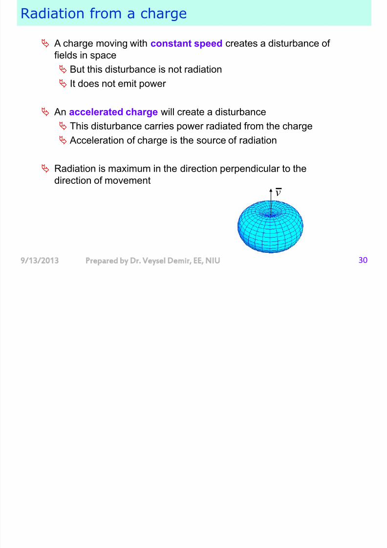
Radiation from a charge
A charge moving with constant speed creates a disturbance of
fields in space
But this disturbance is not radiation
It does not emit power
An accelerated charge will create a disturbance
This disturbance carries power radiated from the charge Acceleration of charge is the source of radiation
Radiation is maximum in the direction perpendicular to the
direction of movement
v
R di ti

7/29/2019 Antenna Theory and Design Slides 1
http://slidepdf.com/reader/full/antenna-theory-and-design-slides-1 31/86
9/13/2013 Prepared by Dr. Veysel Demir, EE, NIU 31
Radiation
An accelerated charge will create radiation
Time-varying current will create radiation
Why don’t we observe radiation from an AC circuit?
dQ t
I t dt
I t
E t
E t
R di ti f t i i li

7/29/2019 Antenna Theory and Design Slides 1
http://slidepdf.com/reader/full/antenna-theory-and-design-slides-1 32/86
9/13/2013 Prepared by Dr. Veysel Demir, EE, NIU 32
Radiation from a transmission line
I
I
R di ti

7/29/2019 Antenna Theory and Design Slides 1
http://slidepdf.com/reader/full/antenna-theory-and-design-slides-1 33/86
9/13/2013 Prepared by Dr. Veysel Demir, EE, NIU 33
Radiation
E t
If the distance between the wires is small (compared with thewavelength) the radiated fields from the wires will cancel each other.
Consequently, radiation is negligible, and is neglected in low-frequencya-c circuit theory.
At high frequencies, wavelength is shorter
If the wavelength is comparable with the distance, then there will be
radiation.
R di ti

7/29/2019 Antenna Theory and Design Slides 1
http://slidepdf.com/reader/full/antenna-theory-and-design-slides-1 34/86
9/13/2013 Prepared by Dr. Veysel Demir, EE, NIU 34
Radiation
For radiation to occur, the conductor carrying the
current must be reasonably ―in the clear,‖ that is, not enclosed by obstacles that are impenetrable to
electromagnetic waves.
Radiation may be prevented, when desired, byplacing circuits inside closed metallic enclosures; this
is the principle of shielding .
Radiation f om a t ansmission line

7/29/2019 Antenna Theory and Design Slides 1
http://slidepdf.com/reader/full/antenna-theory-and-design-slides-1 35/86
9/13/2013 Prepared by Dr. Veysel Demir, EE, NIU 35
Radiation from a transmission line
An open ended transmission line:
Since the end is open, we will observe
standing waves of voltage and currenton the transmission line
magnitude of current (standing
wave pattern)
current
charges
E fields from
top wire
E fields from
bottom wire
H fields from
top wire
H fields from
bottom wire
Although the charges are oscillating(accelerating) sinusoidally, this
structure does not radiate
The radiation from the two wires
cancel each other
What happens if we bend the ends

7/29/2019 Antenna Theory and Design Slides 1
http://slidepdf.com/reader/full/antenna-theory-and-design-slides-1 36/86
9/13/2013 Prepared by Dr. Veysel Demir, EE, NIU 36
What happens if we bend the ends
Direction of maximum radiation
The fields generated by the arms
add up and radiate
Antenna Parameters

7/29/2019 Antenna Theory and Design Slides 1
http://slidepdf.com/reader/full/antenna-theory-and-design-slides-1 37/86
9/13/2013 Prepared by Dr. Veysel Demir, EE, NIU 379/13/2013
Antenna Parameters
The ideal antenna is one that will
radiate all the power delivered to it by a transmissionline
in the desired direction or directions
and with the desired polarization.
Practical antennas can never fully achieve thisideal performance
Their merit is conveniently described in terms of the degree to which they do so.
Antenna Parameters

7/29/2019 Antenna Theory and Design Slides 1
http://slidepdf.com/reader/full/antenna-theory-and-design-slides-1 38/86
9/13/2013 Prepared by Dr. Veysel Demir, EE, NIU 38
Antenna Parameters
The principal parameters of antennas are radiation pattern
radiation efficiency input impedance
bandwidth
Other parameters defined under each of these categories gain
beamwidth beam polarization
minor lobe level,
radiation efficiency,
aperture efficiency,
effective area,
radiation resistance, various ―bandwidths,‖
Some of these parameters are interrelated or correlated.
Antenna structures Size

7/29/2019 Antenna Theory and Design Slides 1
http://slidepdf.com/reader/full/antenna-theory-and-design-slides-1 39/86
9/13/2013 Prepared by Dr. Veysel Demir, EE, NIU 39
Antenna structures - Size
There is a general proportionality between
antenna size and the wavelength at the frequency of operation,
but this relationship is not hard and fast.
Large antennas are sometimes used at short wavelengths (high
frequencies) to obtain a highly directional radiation pattern(beam) and high gain in a preferred direction.
At long wavelengths (low frequencies) very small antennas maybe used for reception when efficiency is not important.
An antenna appreciably less than a half wavelength is termed―electrically small.‖
Even a physically large antenna may be electrically small at verylow frequencies.
Antenna structures Feed Lines

7/29/2019 Antenna Theory and Design Slides 1
http://slidepdf.com/reader/full/antenna-theory-and-design-slides-1 40/86
9/13/2013 Prepared by Dr. Veysel Demir, EE, NIU 40
Antenna structures - Feed Lines
Part of antenna design:
The design of a feed line (transmission line) any necessary impedance-matching devices
power-dividing devices
Transmission lines:
Wavegides Coaxial cables
Two-wire lines
Microstrip lines
Stripline lines
Coplanar waveguides
The line connects to the antenna at its input terminalsor input port.
Antenna structures Conductors and isolators

7/29/2019 Antenna Theory and Design Slides 1
http://slidepdf.com/reader/full/antenna-theory-and-design-slides-1 41/86
9/13/2013 Prepared by Dr. Veysel Demir, EE, NIU 41
Antenna structures – Conductors and isolators
Metals of high conductivity, such as copper and
aluminum (and its alloys), are naturally preferred.
The conducting portions of an antenna not only carry
rf currents but also have rf voltages between their
different parts and between the conductors andground.
To avoid ―short circuiting‖ these voltage, insulators
must sometimes be used between the antenna andits supports, or between different parts of the
antenna.
Antenna structures Weather protection

7/29/2019 Antenna Theory and Design Slides 1
http://slidepdf.com/reader/full/antenna-theory-and-design-slides-1 42/86
9/13/2013 Prepared by Dr. Veysel Demir, EE, NIU 42
Antenna structures – Weather protection
Since antennas are ordinarily ―outdoors,‖ they mustwithstand wind, rain, ice and snow, lightning, andsometimes corrosive gases or salt-laden air.
Sometimes an antenna (such as a rotatingparaboloidal reflector or lens) is totally enclosed in a
protective housing of low-loss insulating material thatis practically transparent to the electromagneticradiation.
Such a housing is called a radome.
Radiation Pattern

7/29/2019 Antenna Theory and Design Slides 1
http://slidepdf.com/reader/full/antenna-theory-and-design-slides-1 43/86
9/13/2013 Prepared by Dr. Veysel Demir, EE, NIU 43
Radiation Pattern
If an antenna is imagined to be located at the center of
a spherical coordinate system, its radiation pattern is determined by measuring the electric field
intensity over the surface of a sphere at some fixed distance, r .
A pattern that represents field strength as a function of
angular direction at a fixed distance from the antenna is
identical to a plot of distance for a constant field
strength.
Since the field E is then a function of the two variable
and , it is written E ( , ) in functional notation.
ˆ, sin4
j R I z e E j
R
Example
Radiation Pattern

7/29/2019 Antenna Theory and Design Slides 1
http://slidepdf.com/reader/full/antenna-theory-and-design-slides-1 44/86
9/13/2013 Prepared by Dr. Veysel Demir, EE, NIU 44
Radiation Pattern
The power density of the field, p ( , ), can also be computedwhen E ( , ) is known
A plot in terms of p( , ) conveys the same information as a plotof the magnitude of E ( , ).
The phase pattern In some circumstances, the phase of the field is of interest, and a
plot may be made of the phase angle of E ( , ) as well as itsmagnitude;
Ordinarily antenna pattern implies only the magnitude of E or p.
The polarization pattern
Sometimes the polarization properties of E may also be plotted.
2 377 p E
Patterns in a plane

7/29/2019 Antenna Theory and Design Slides 1
http://slidepdf.com/reader/full/antenna-theory-and-design-slides-1 45/86
9/13/2013 Prepared by Dr. Veysel Demir, EE, NIU 45
Patterns in a plane
Principal planes of the coordinate system
xy-plane: = 90o,
=0 o
-360 o
xz-plane: = 0o-180o, =0 o
yz-plane: = 0o-180o, =90 o
Patterns in a plane

7/29/2019 Antenna Theory and Design Slides 1
http://slidepdf.com/reader/full/antenna-theory-and-design-slides-1 46/86
9/13/2013 Prepared by Dr. Veysel Demir, EE, NIU 46
Patterns in a plane
xy-plane
xz-plane
yz-plane
Polar plot vs rectangular coordinate plot

7/29/2019 Antenna Theory and Design Slides 1
http://slidepdf.com/reader/full/antenna-theory-and-design-slides-1 47/86
9/13/2013 Prepared by Dr. Veysel Demir, EE, NIU 47
Polar plot vs rectangular coordinate plot
Rectangular coordinate plot
distorts the appearance of the pattern geometrically
but preserves the
interpretability of an angle
representation and makesthe plotting and reading of
the low-amplitude portions
of the pattern easier.
E-plane and H-plane

7/29/2019 Antenna Theory and Design Slides 1
http://slidepdf.com/reader/full/antenna-theory-and-design-slides-1 48/86
9/13/2013 Prepared by Dr. Veysel Demir, EE, NIU 48
E plane and H plane
When the radiation of an antenna is polarized so that the E -vector lies in a plane (usually one of the principal planes), thepattern in this plane is sometimes referred to as the E -plane
pattern;
and the pattern in the plane perpendicular to it, in which the H -vector lies, is called the H -plane pattern.
ˆsin4
j R I z e H j
R
ˆsin4
j R I z e
E j R
Example
E-plane H-plane
3D view
Absolute and relative patterns

7/29/2019 Antenna Theory and Design Slides 1
http://slidepdf.com/reader/full/antenna-theory-and-design-slides-1 49/86
9/13/2013 Prepared by Dr. Veysel Demir, EE, NIU 49
Absolute and relative patterns
Absolute pattern: if radiation pattern is plotted in
terms of the electric field strength in volts per meter
or the power density in watts per square meter.
Relative pattern: Often, the pattern is plotted inrelative terms, that is, the field strength or power density is represented in terms of its ratio to somereference value.
The reference usually chosen is the field level in the
maximum-field-strength direction.
( , )( , ) ( , )
(max)rel
E F E
E
( , )( , ) ( , )
(max)rel
S P S
S
normalized field patternpower pattern
Example

7/29/2019 Antenna Theory and Design Slides 1
http://slidepdf.com/reader/full/antenna-theory-and-design-slides-1 50/86
9/13/2013 Prepared by Dr. Veysel Demir, EE, NIU 50
Example
For an element of current (ideal dipole):
sin4
j R I z e E j
R
2(max) 4
j R I z e
E j R
( , ) ( , ) sinrel F E
Decibel scale

7/29/2019 Antenna Theory and Design Slides 1
http://slidepdf.com/reader/full/antenna-theory-and-design-slides-1 51/86
9/13/2013 Prepared by Dr. Veysel Demir, EE, NIU 51
Decibel scale
It is fairly common to express the relative field
strength F or power density P in decibels.The value at the maximum of the pattern is
therefore zero decibels,
and at other angles the decibel values are
negative (since the logarithm of a fractionalnumber is negative
10 1010log ( , ) 20log ( , ) P F
2( , ) ( , ) P F
Power pattern

7/29/2019 Antenna Theory and Design Slides 1
http://slidepdf.com/reader/full/antenna-theory-and-design-slides-1 52/86
9/13/2013 Prepared by Dr. Veysel Demir, EE, NIU 529/13/2013 Prepared by Dr. Veysel Demir, EE, NIU 52
Power patternA normalized power pattern for a uniform line source
polar – linear scale polar – dB scale
rectangular – dB scalerectangular – linear scale
Near-field and far-field

7/29/2019 Antenna Theory and Design Slides 1
http://slidepdf.com/reader/full/antenna-theory-and-design-slides-1 53/86
9/13/2013 Prepared by Dr. Veysel Demir, EE, NIU 53
Near field and far field
Antenna radiation patterns are graphical
representations of the radiation in the far-field of theantenna.
The far-field region is where the angular fielddistribution is essentially independent of the distancefrom the antenna.
The minimum permissible distance, for a far-fieldmeasurement, depends on the dimensions of theantenna in relation to the wavelength.
The distance from the antenna where the far-field begins:
22 ff
Dr
D: maximum dimension of antenna
Farfield conditions

7/29/2019 Antenna Theory and Design Slides 1
http://slidepdf.com/reader/full/antenna-theory-and-design-slides-1 54/86
9/13/2013 Prepared by Dr. Veysel Demir, EE, NIU 54
Farfield conditions
22 Dr
r Dr
Farfield conditions
3
23
2
0 0.62
20.62
2
D
D D
D
r: Distance from antenna
Reactive near field
Radiating near field
Far field
The near-field region is further subdivided between
the reactive near-field and radiating near-field
regions.
However, the total field present is actually the vector
sum of the reactive and radiating fields..
The Ideal Dipole – Near and farfields

7/29/2019 Antenna Theory and Design Slides 1
http://slidepdf.com/reader/full/antenna-theory-and-design-slides-1 55/86
9/13/2013 Prepared by Dr. Veysel Demir, EE, NIU 55
The Ideal Dipole Near and farfields
Hertzian electric dipole, infinitesimal dipole, elemental dipole
x
y
z
I
Assumptions:
The line is electrically very short
The current I is uniform on the line
0 sin 2 I t I ft
See Section 2.3 in the text book
Magnetic field:1
ˆ1 sin4
j r I z e H j
j r r
Example: The Ideal (elemental or Hertzian) Dipole
7/29/2019 Antenna Theory and Design Slides 1
http://slidepdf.com/reader/full/antenna-theory-and-design-slides-1 56/86
9/13/2013 Prepared by Dr. Veysel Demir, EE, NIU 56
p ( ) p
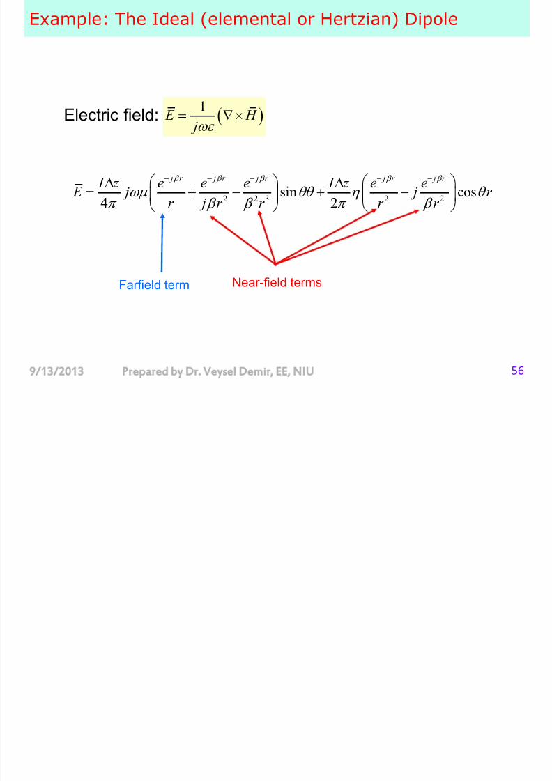
Electric field: 1
E H j
Farfield term Near-field terms
2 2 3 2 2ˆ ˆsin cos
4 2
j r j r j r j r j r
I z e e e I z e e E j j r r j r r r r
Farfields

7/29/2019 Antenna Theory and Design Slides 1
http://slidepdf.com/reader/full/antenna-theory-and-design-slides-1 57/86
9/13/2013 Prepared by Dr. Veysel Demir, EE, NIU 57
Farfields
If ˆsin
4
j r I z e H j
r
ˆsin4
j r
I z e E jr
1r
Farfield terms
sin4
sin4
j r
j r
I z e j
E r
I z e H jr
Intrinsic
impedance
Farfield Power Density

7/29/2019 Antenna Theory and Design Slides 1
http://slidepdf.com/reader/full/antenna-theory-and-design-slides-1 58/86
9/13/2013 Prepared by Dr. Veysel Demir, EE, NIU 58
a e d o e e s ty
2
1ˆ ˆ
sin sin2 4 4
sinˆ
2 4
j r j r I z e I z e
S E H j jr r
I z r
r
2
sinˆ
2 4
I z real S real r
R
Real power density propagating:
Farfield Power Density

7/29/2019 Antenna Theory and Design Slides 1
http://slidepdf.com/reader/full/antenna-theory-and-design-slides-1 59/86
9/13/2013 Prepared by Dr. Veysel Demir, EE, NIU 59
y
Total power flowing out through a sphere with radius R
22
2
0 0
2
sinˆ ˆ sin
2 4
12
r
I z P S ds r rr d d
r
I z
Radiated power
The Nearfields of Ideal Dipole

7/29/2019 Antenna Theory and Design Slides 1
http://slidepdf.com/reader/full/antenna-theory-and-design-slides-1 60/86
9/13/2013 Prepared by Dr. Veysel Demir, EE, NIU 60
p
Magnetic field:2
ˆsin4
j r nf I ze H
r
Electric field:3 3
ˆˆsin cos
4 2
j r j r nf I z e I z e
E j j r
r r
If 1 R
2
2
5
1 1ˆ
ˆ
2 2
1ˆ
ˆsin sin2 4
nf nf nf nf nf nf nf
RS E H E H r E H
j I z r
r
Poynting vector:
Imaginary: so this is not real power
Example

7/29/2019 Antenna Theory and Design Slides 1
http://slidepdf.com/reader/full/antenna-theory-and-design-slides-1 61/86
9/13/2013 Prepared by Dr. Veysel Demir, EE, NIU 61
p
Radiation Pattern of a Uniform Line Source

7/29/2019 Antenna Theory and Design Slides 1
http://slidepdf.com/reader/full/antenna-theory-and-design-slides-1 62/86
9/13/2013 Prepared by Dr. Veysel Demir, EE, NIU 62
For a uniform line source:
0sin cos / 2
sin4 cos / 2
j R L j I Le E
R L
0
2
(max)4
j R j I Le E
R
sin cos / 2( , ) sin
cos / 2
L F
L
For an element of current (ideal dipole):
( , ) sin F
Element factor – pattern factor

7/29/2019 Antenna Theory and Design Slides 1
http://slidepdf.com/reader/full/antenna-theory-and-design-slides-1 63/86
9/13/2013 Prepared by Dr. Veysel Demir, EE, NIU 63
p
( , ) ( , ) ( , ) F g f
A normalized field pattern can be written as product of
element factor and pattern factor
element
factor
pattern
factor
For a uniform line source:
sin / 2 cos
( , ) sin /2 cos
L
F L
element
factor pattern
factor
Ideal
dipole
A line source can be
considered as a combination
of Ideal dipoles
Line
source
Radiation pattern parameters

7/29/2019 Antenna Theory and Design Slides 1
http://slidepdf.com/reader/full/antenna-theory-and-design-slides-1 64/86
9/13/2013 Prepared by Dr. Veysel Demir, EE, NIU 649/13/2013 Prepared by Dr. Veysel Demir, EE, NIU 64
p p
Major lobe, main lobe, main beam: The radiation lobe
containing the direction of maximum radiation.
Minor lobe: any lobe other than the main lobe.Side lobes
Back lobes: directly opposite to the main lobe
Beamwidth

7/29/2019 Antenna Theory and Design Slides 1
http://slidepdf.com/reader/full/antenna-theory-and-design-slides-1 65/86
9/13/2013 Prepared by Dr. Veysel Demir, EE, NIU 65
When the radiated power of an antenna is
concentrated into a single major ―lobe,‖ the angular width of this lobe is the beamwidth.
Some antennas have a pattern consisting of many
lobes.
Generally a narrower beam implies a greater gain. Beam may have different widths in different planes
through the beam axis
Therefore it is customary to give the widths of the beam in
two planes at right angles, usually the principal planes of thecoordinate system.
Radiation pattern parameters

7/29/2019 Antenna Theory and Design Slides 1
http://slidepdf.com/reader/full/antenna-theory-and-design-slides-1 66/86
9/13/2013 Prepared by Dr. Veysel Demir, EE, NIU 669/13/2013 Prepared by Dr. Veysel Demir, EE, NIU 66
Half power beam width (HP) : Angular separation of the
points where the main beam of the power pattern equals
one-half the maximum value., , HP left HP right HP
For an element of current (ideal dipole): ( , ) sinrel E
1sin 45 , 135 135 45 902
o o o o o HP
2 1 HP
Radiation pattern parameters

7/29/2019 Antenna Theory and Design Slides 1
http://slidepdf.com/reader/full/antenna-theory-and-design-slides-1 67/86
9/13/2013 Prepared by Dr. Veysel Demir, EE, NIU 679/13/2013 Prepared by Dr. Veysel Demir, EE, NIU 67
Side lobe level (SLL) : A measure how well the power is
concentrated into the main beam.
( ) pattern valueof sidelobepeak
pattern valueof themain lobe (max)
E SLLSLL
E
10
0.39
20log ( ) 8.2dB
SLL
SLL SLL dB
Radiation pattern parameters

7/29/2019 Antenna Theory and Design Slides 1
http://slidepdf.com/reader/full/antenna-theory-and-design-slides-1 68/86
9/13/2013 Prepared by Dr. Veysel Demir, EE, NIU 6868
Broadside: The main beam is in a direction normal to the
plane containing the antenna
Endfire: Main beam is in the plane containing the antenna
Fan beam
Pencil beam
Radiation Resistance and Efficiency

7/29/2019 Antenna Theory and Design Slides 1
http://slidepdf.com/reader/full/antenna-theory-and-design-slides-1 69/86
9/13/2013 Prepared by Dr. Veysel Demir, EE, NIU 69
In a large class of antennas the radiation is associated with a flow of RF current in a conductor or conductors.
Thus, when a current I flows in a resistance R , an amount of power P = RI 2 will be dissipated and converted into heat.
In general, the input impedance of an antenna is complex.
Resistive part is the sum of radiation resistance and loss
in
Z
( )in radiation loss ohmic Z R R jX
Antenna Impedance

7/29/2019 Antenna Theory and Design Slides 1
http://slidepdf.com/reader/full/antenna-theory-and-design-slides-1 70/86
9/13/2013 Prepared by Dr. Veysel Demir, EE, NIU 70
For most antennas
Ohmic loss is significant for electrically small antennas
ohmic radiation R R
The input impedance of an antenna at its terminals:
The power that leaves the antenna and never returns (radiation)
Ohmic losses associated with heating
A A A Z R jX
in radiation ohmic R R R
radiation R
ohmic R
A X : power stored in the near field
The input impedance of antenna is the same when receiving and
transmitting (reciprocity)
Input impedance is affected by the other antennas around
Antenna Impedance

7/29/2019 Antenna Theory and Design Slides 1
http://slidepdf.com/reader/full/antenna-theory-and-design-slides-1 71/86
9/13/2013 Prepared by Dr. Veysel Demir, EE, NIU 71
Average power dissipated in the antenna 21
2in A A P R I
A I : current at the antenna terminal
2 21 1
2 2in ohmic rad A ohmic A P P P R I R I 2
2 rad rad
A
P R
I
2
12rad P I z
For an element of current (ideal dipole):
2
2
2 2 212
2
2
2 2
2 22
6 6
2 1 2 22 26 6 3
I z rad
rad I
A
p
P R z f z
I
u z z z
2
280 ( )rad
z R
For an ideal dipole the radiation
resistance is very small
Antenna Impedance

7/29/2019 Antenna Theory and Design Slides 1
http://slidepdf.com/reader/full/antenna-theory-and-design-slides-1 72/86
9/13/2013 Prepared by Dr. Veysel Demir, EE, NIU 72
Radiation efficiencyrad rad rad rad
r
in ohmic rad rad ohmic in
P P R Rk
P P P R R R
Ohmic resistance of wire antenna
At high frequencies the skin depth is : 2
Surface resistance :2
s R
Ohmic resistance of wire antenna with uniform current:
, : wire radius, : length2
ohmic s L R R a L
a
Bandwidth

7/29/2019 Antenna Theory and Design Slides 1
http://slidepdf.com/reader/full/antenna-theory-and-design-slides-1 73/86
9/13/2013 Prepared by Dr. Veysel Demir, EE, NIU 73
All antennas are limited in the range of frequency over whichthey will operate satisfactorily.
This frequency range, whatever it may be, is called thebandwidth of the antenna.
Some antennas are required to operate only at a fixedfrequency with a signal that is narrow in its bandwidth;
consequently there is no bandwidth problem in designing such anantenna.
But in other applications much greater bandwidths may be
required; in such cases special techniques are needed.
Bandwidth

7/29/2019 Antenna Theory and Design Slides 1
http://slidepdf.com/reader/full/antenna-theory-and-design-slides-1 74/86
9/13/2013 Prepared by Dr. Veysel Demir, EE, NIU 74
Bandwidth as a percent of the center frequency
Bandwidth as a ratio
Antenna pattern: pattern bandwidth The beamwidth, gain, sidelobe level, beam direction, and
polarization are parameters associated with the pattern
bandwidth
Input impedance: impedance bandwidth
input impedance, radiation resistance, and efficiency are
associated with the impedance bandwidth.
100%U L
P C
f f B
f
U r
L
f B
f
Bandwidth
7/29/2019 Antenna Theory and Design Slides 1
http://slidepdf.com/reader/full/antenna-theory-and-design-slides-1 75/86
9/13/2013 Prepared by Dr. Veysel Demir, EE, NIU 75
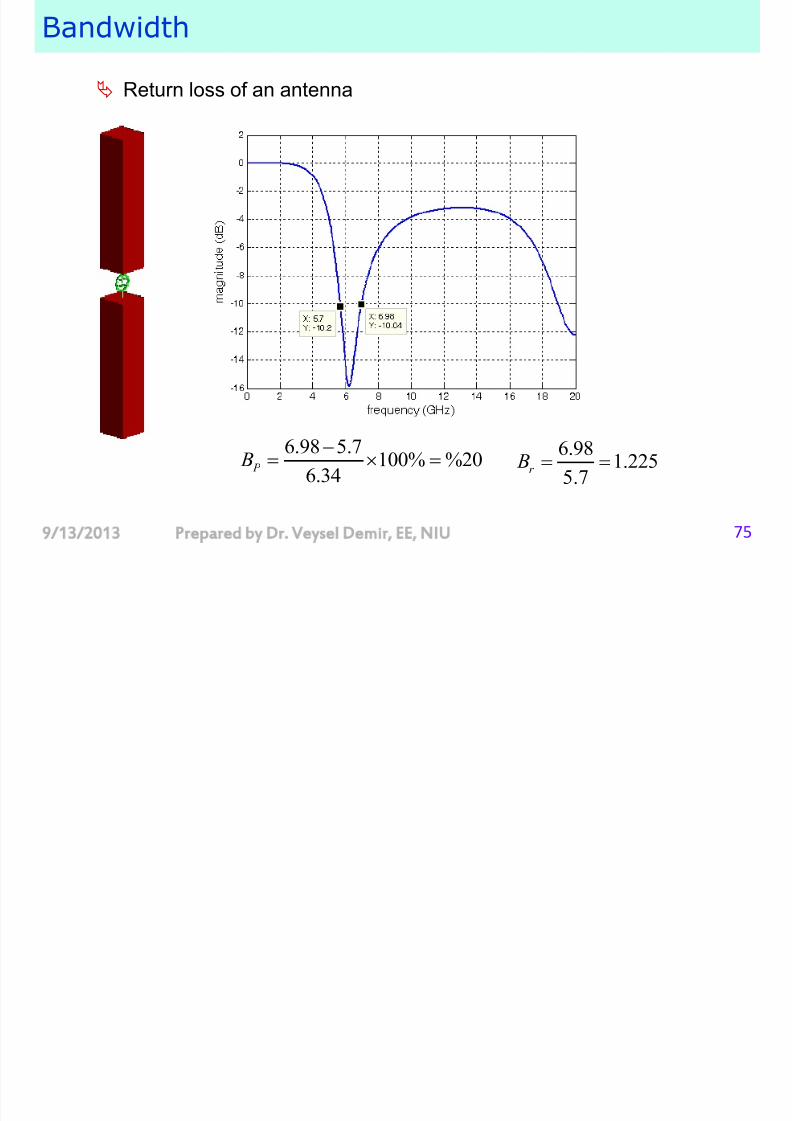
Return loss of an antenna
6.98 5.7100% %20
6.34 P B
6.981.225
5.7r B
Directivity and Gain

7/29/2019 Antenna Theory and Design Slides 1
http://slidepdf.com/reader/full/antenna-theory-and-design-slides-1 76/86
9/13/2013 Prepared by Dr. Veysel Demir, EE, NIU 76
Isotropic radiator:
The source radiates power at a constant rate uniformly in all
directions,
The total power flowing through any spherical surface centered at the
source will be uniformly distributed over the surface and must equal the
total power radiated.
24
t R
P S R
P t = total power S R = power density at a distance R
R
R p Actually an isotropic radiator is not physically realizable;
All actual antennas have some degree of nonuniformity
in their radiation patterns.
A nonisotropic antenna will radiate more power in some
directions than in others and therefore has a directional
pattern.
Solid angle

7/29/2019 Antenna Theory and Design Slides 1
http://slidepdf.com/reader/full/antenna-theory-and-design-slides-1 77/86
9/13/2013 Prepared by Dr. Veysel Demir, EE, NIU 77
Solid angle is the angle that, seen from the center of a sphere,includes a given area on the surface of the sphere.
The value of the solid angle is numerically equal to the size of that area divided by the square the radius of the sphere.
Mathematically the solid angle is unitless, but for practicalreasons the steradian (s.r.) is assigned so that 1 steradian = 1 radian2.
22
0 0
22 2
0 0
sin
4
sphere Area dA r d d
r d r
2 2
sin
4
4
d d d
r d r
d Element of solid angle
Radiation intensity

7/29/2019 Antenna Theory and Design Slides 1
http://slidepdf.com/reader/full/antenna-theory-and-design-slides-1 78/86
9/13/2013 Prepared by Dr. Veysel Demir, EE, NIU 78
Total power radiated by an antenna can be
calculated as
Radiation intensity is a range-independent quantity
Total radiated power equals the sum of all radiation
intensity that encloses the antenna.
2 2
2 2 2
0 0 0 0, , sin , ,t P r dA S r r d d S r r d
2, , ,U S r r
2 2
0 0 0 0, sin ,
t P U d d U d
Directivity

7/29/2019 Antenna Theory and Design Slides 1
http://slidepdf.com/reader/full/antenna-theory-and-design-slides-1 79/86
9/13/2013 Prepared by Dr. Veysel Demir, EE, NIU 79
(Maximum) Directivity D is a quantitative measure of an
antenna’s ability to concentrate energy in a certain direction.
Specifically, D is the ratio of the maximum radiation intensityU max to the average radiation intensity U av .
Directivity: (directive gain) the ratio of the radiation intensity in a
certain direction to the average radiation intensity
max
ave
U D
U
( , )
( , ) ave
U
D U
Directivity as a function of direction( , ) D
Maximum directivity D
Directivity

7/29/2019 Antenna Theory and Design Slides 1
http://slidepdf.com/reader/full/antenna-theory-and-design-slides-1 80/86
9/13/2013 Prepared by Dr. Veysel Demir, EE, NIU 80
If the radiation is isotropic, the radiation intensity in every
direction is U av .
Directivity:
Directivity is calculated by integrating relative values of an
antenna’s radiation pattern,
and this does not require knowledge of an absolute value
24t
isotropic P S R
2
24
t ave
P U r r
4t ave
P U
max max max
2
20 0
0 0max
4 4 4
,, sinave t
U U U D
U P U U d d d U
2
2
max max max
, , , , ,,
, , , ,
U S r E r F
U S r E r
Directivity

7/29/2019 Antenna Theory and Design Slides 1
http://slidepdf.com/reader/full/antenna-theory-and-design-slides-1 81/86
9/13/2013 Prepared by Dr. Veysel Demir, EE, NIU 81
Beam solid angle: is the solid angle through which all the
power would be radiated if the radiation intensity equaled the
maximum over the beam area.
2
0 0 max
4 4
,sin
A
DU
d d U
maxt A P U
A
2
0 0max
,sin A
U d d
U
A
Gain

7/29/2019 Antenna Theory and Design Slides 1
http://slidepdf.com/reader/full/antenna-theory-and-design-slides-1 82/86
9/13/2013 Prepared by Dr. Veysel Demir, EE, NIU 82
Gain: (power gain)
The directivity is based on the radiated power , P r .
The gain is based on the input power to the antenna, P i . The gain therefore accounts for the efficiency of the antenna as
well
max max max4
/ 4ave r r
U U U D
U P P
max4
in
U G
P
Radiation efficiencyr
in
P k
P
G kD
, ,G kD
Gain as a function of direction( , )G
Maximum gainG
Directivity and Gain in Decibels

7/29/2019 Antenna Theory and Design Slides 1
http://slidepdf.com/reader/full/antenna-theory-and-design-slides-1 83/86
9/13/2013 Prepared by Dr. Veysel Demir, EE, NIU 83
Directivity
Gain
Relative Gain: Frequently gain is used to describe the
performance of an antenna relative to some standard
reference antenna
1010logdB D D
1010logdBG G
max
max,ref
U G
U
Gain relative to a half-wave dipole: dBd
Gain relative to an isotropic antenna: dBi
Gain of half-wave dipole is given as 2.15 dBi
Gain of an X antenna is given as 6.1 dBi
The gain of the X antenna relative to half-
wave dipole:Gd=6.1-2.15 = 3.95 dBd
Example

7/29/2019 Antenna Theory and Design Slides 1
http://slidepdf.com/reader/full/antenna-theory-and-design-slides-1 84/86
9/13/2013 Prepared by Dr. Veysel Demir, EE, NIU 8484
The pattern expression for an omni-directional antenna is given as:
1 21,( , ) 3 3
0,rel
E
otherwise
Find the beam solid angle and maximum directivity D. A
222 23
03
2
3
3
( , ) 1 sin
2 cos 2
A rel E d d d
4 42
2 A
D
( , )rel E
maxt A P U
max4
r
U D
P
Example

7/29/2019 Antenna Theory and Design Slides 1
http://slidepdf.com/reader/full/antenna-theory-and-design-slides-1 85/86
9/13/2013 Prepared by Dr. Veysel Demir, EE, NIU 8585
Determine the electric field intensity at a distance of 10 km from an antenna (in the
direction of maximum radiation) having maximum directivity 5 dB and radiating a
total power 20 KW.
0.5
105 10log ( ) 10 3.162 D D
max max max4
/ 4ave
U U U D
U P P
max
4
DP U
2
max maxU S r
max24
DP S
r
-5
max2
3.162 200005.032479 10
4 10000S
2
max max max
10.1948 /
2S E E V m
Example

7/29/2019 Antenna Theory and Design Slides 1
http://slidepdf.com/reader/full/antenna-theory-and-design-slides-1 86/86
The radiation intensity of an antenna is given as
32sin sin , 0 ,0 ,
( , ) 0,U otherwise
Find the directivity D.
max
ave
U DU
max 2U 1 ( , )
4aveU U d
3
0 0
2 3 3 2
0 0 0 0
1( , ) 2 sin sin sin
4
1 1sin sin sin sin
2 2
1
aveU U d d d
d d d d
2U
( , ) E