antenna theory - download.e-bookshelf.de
TRANSCRIPT


ANTENNA THEORY


ANTENNA THEORYANALYSIS AND DESIGN
THIRD EDITION
Constantine A. Balanis
A JOHN WILEY & SONS, INC., PUBLICATION

Copyright 2005 by John Wiley & Sons, Inc. All rights reserved.
Published by John Wiley & Sons, Inc., Hoboken, New Jersey.Published simultaneously in Canada.
No part of this publication may be reproduced, stored in a retrieval system, or transmitted in any form orby any means, electronic, mechanical, photocopying, recording, scanning, or otherwise, except aspermitted under Section 107 or 108 of the 1976 United States Copyright Act, without either the priorwritten permission of the Publisher, or authorization through payment of the appropriate per-copy fee tothe Copyright Clearance Center, Inc., 222 Rosewood Drive, Danvers, MA 01923, 978-750-8400, fax978-646-8600, or on the web at www.copyright.com. Requests to the Publisher for permission should beaddressed to the Permissions Department, John Wiley & Sons, Inc., 111 River Street, Hoboken, NJ 07030,(201) 748-6011, fax (201) 748-6008.
Limit of Liability/Disclaimer of Warranty: While the publisher and author have used their best efforts inpreparing this book, they make no representations or warranties with respect to the accuracy orcompleteness of the contents of this book and specifically disclaim any implied warranties ofmerchantability or fitness for a particular purpose. No warranty may be created or extended by salesrepresentatives or written sales materials. The advice and strategies contained herein may not be suitablefor your situation. You should consult with a professional where appropriate. Neither the publisher norauthor shall be liable for any loss of profit or any other commercial damages, including but not limited tospecial, incidental, consequential, or other damages.
For general information on our other products and services please contact our Customer Care Departmentwithin the U.S. at 877-762-2974, outside the U.S. at 317-572-3993 or fax 317-572-4002.
Wiley also publishes its books in a variety of electronic formats. Some content that appears in print,however, may not be available in electronic format.
Library of Congress Cataloging-in-Publication Data is available.
ISBN: 0-471-66782-X
Printed in the United States of America.
10 9 8 7 6 5 4 3 2 1

To the memory of my parents, uncle and aunt
�τη µvηµη τωv γovεωv, τov θειov και της θειας µov


Contents
Preface xiii
1 Antennas 1
1.1 Introduction 11.2 Types of Antennas 41.3 Radiation Mechanism 71.4 Current Distribution on a Thin Wire Antenna 171.5 Historical Advancement 201.6 Multimedia 24
References 24
2 Fundamental Parameters of Antennas 27
2.1 Introduction 272.2 Radiation Pattern 272.3 Radiation Power Density 382.4 Radiation Intensity 402.5 Beamwidth 422.6 Directivity 442.7 Numerical Techniques 582.8 Antenna Efficiency 642.9 Gain 65
2.10 Beam Efficiency 692.11 Bandwidth 702.12 Polarization 702.13 Input Impedance 802.14 Antenna Radiation Efficiency 852.15 Antenna Vector Effective Length and Equivalent Areas 872.16 Maximum Directivity and Maximum Effective Area 922.17 Friis Transmission Equation and Radar Range Equation 942.18 Antenna Temperature 1042.19 Multimedia 108
References 112Problems 114
vii

viii CONTENTS
3 Radiation Integrals and Auxiliary Potential Functions 133
3.1 Introduction 1333.2 The Vector Potential A for an Electric Current Source J 1353.3 The Vector Potential F for a Magnetic Current Source M 1373.4 Electric and Magnetic Fields for Electric (J) and Magnetic (M)
Current Sources 1383.5 Solution of the Inhomogeneous Vector Potential Wave Equation 1393.6 Far-Field Radiation 1423.7 Duality Theorem 1443.8 Reciprocity and Reaction Theorems 144
References 150Problems 150
4 Linear Wire Antennas 151
4.1 Introduction 1514.2 Infinitesimal Dipole 1514.3 Small Dipole 1624.4 Region Separation 1654.5 Finite Length Dipole 1704.6 Half-Wavelength Dipole 1824.7 Linear Elements Near or on Infinite Perfect Conductors 1844.8 Ground Effects 2054.9 Computer Codes 214
4.10 Multimedia 217References 218Problems 219
5 Loop Antennas 231
5.1 Introduction 2315.2 Small Circular Loop 2325.3 Circular Loop of Constant Current 2465.4 Circular Loop with Nonuniform Current 2555.5 Ground and Earth Curvature Effects for Circular Loops 2615.6 Polygonal Loop Antennas 2635.7 Ferrite Loop 2665.8 Mobile Communication Systems Applications 2685.9 Multimedia 269
References 273Problems 275
6 Arrays: Linear, Planar, and Circular 283
6.1 Introduction 2836.2 Two-Element Array 2846.3 N -Element Linear Array: Uniform Amplitude and Spacing 2906.4 N -Element Linear Array: Directivity 313
CONTENTS ix
6.5 Design Procedure 3186.6 N -Element Linear Array: Three-Dimensional Characteristics 3206.7 Rectangular-to-Polar Graphical Solution 3226.8 N -Element Linear Array: Uniform Spacing, Nonuniform
Amplitude 3246.9 Superdirectivity 345
6.10 Planar Array 3496.11 Design Considerations 3626.12 Circular Array 3656.13 Multimedia 369
References 370Problems 371
7 Antenna Synthesis and Continuous Sources 385
7.1 Introduction 3857.2 Continuous Sources 3867.3 Schelkunoff Polynomial Method 3887.4 Fourier Transform Method 3937.5 Woodward-Lawson Method 3997.6 Taylor Line-Source (Tschebyscheff-Error) 4067.7 Taylor Line-Source (One-Parameter) 4107.8 Triangular, Cosine, and Cosine-Squared Amplitude Distributions 4177.9 Line-Source Phase Distributions 418
7.10 Continuous Aperture Sources 4197.11 Multimedia 423
References 423Problems 424
8 Integral Equations, Moment Method, and Self and MutualImpedances 433
8.1 Introduction 4338.2 Integral Equation Method 4348.3 Finite Diameter Wires 4428.4 Moment Method Solution 4508.5 Self-Impedance 4588.6 Mutual Impedance Between Linear Elements 4688.7 Mutual Coupling in Arrays 4788.8 Multimedia 491
References 491Problems 494
9 Broadband Dipoles and Matching Techniques 497
9.1 Introduction 4979.2 Biconical Antenna 5009.3 Triangular Sheet, Bow-Tie, and Wire Simulation 5069.4 Cylindrical Dipole 508

x CONTENTS
9.5 Folded Dipole 5159.6 Discone and Conical Skirt Monopole 5219.7 Matching Techniques 5239.8 Multimedia 541
References 542Problems 543
10 Traveling Wave and Broadband Antennas 549
10.1 Introduction 54910.2 Traveling Wave Antennas 54910.3 Broadband Antennas 56610.4 Multimedia 600
References 600Problems 602
11 Frequency Independent Antennas, Antenna Miniaturization, andFractal Antennas 611
11.1 Introduction 61111.2 Theory 61211.3 Equiangular Spiral Antennas 61411.4 Log-Periodic Antennas 61911.5 Fundamental Limits of Electrically Small Antennas 63711.6 Fractal Antennas 64111.7 Multimedia 648
References 648Problems 650
12 Aperture Antennas 653
12.1 Introduction 65312.2 Field Equivalence Principle: Huygens’ Principle 65312.3 Radiation Equations 66012.4 Directivity 66212.5 Rectangular Apertures 66312.6 Circular Apertures 68312.7 Design Considerations 69212.8 Babinet’s Principle 69712.9 Fourier Transforms in Aperture Antenna Theory 701
12.10 Ground Plane Edge Effects: The Geometrical Theory ofDiffraction 721
12.11 Multimedia 726References 726Problems 728
13 Horn Antennas 739
13.1 Introduction 73913.2 E-Plane Sectoral Horn 739

CONTENTS xi
13.3 H -Plane Sectoral Horn 75513.4 Pyramidal Horn 76913.5 Conical Horn 78313.6 Corrugated Horn 78513.7 Aperture-Matched Horns 79213.8 Multimode Horns 79413.9 Dielectric-Loaded Horns 797
13.10 Phase Center 79913.11 Multimedia 802
References 802Problems 805
14 Microstrip Antennas 811
14.1 Introduction 81114.2 Rectangular Patch 81614.3 Circular Patch 84314.4 Quality Factor, Bandwidth, and Efficiency 85214.5 Input Impedance 85514.6 Coupling 85614.7 Circular Polarization 85914.8 Arrays and Feed Networks 86514.9 Multimedia 872
References 872Problems 876
15 Reflector Antennas 883
15.1 Introduction 88315.2 Plane Reflector 88315.3 Corner Reflector 88415.4 Parabolic Reflector 89315.5 Spherical Reflector 93415.6 Multimedia 936
References 937Problems 939
16 Smart Antennas 945
16.1 Introduction 94516.2 Smart-Antenna Analogy 94616.3 Cellular Radio Systems Evolution 94716.4 Signal Propagation 95416.5 Smart Antennas’ Benefits 95716.6 Smart Antennas’ Drawbacks 95816.7 Antenna 95816.8 Antenna Beamforming 96216.9 Mobile Ad hoc Networks (MANETs) 977
16.10 Smart-Antenna System Design, Simulation, and Results 982

xii CONTENTS
16.11 Beamforming, Diversity Combining, Rayleigh-Fading, andTrellis-Coded Modulation 990
16.12 Other Geometries 99316.13 Multimedia 994
References 995Problems 999
17 Antenna Measurements 1001
17.1 Introduction 100117.2 Antenna Ranges 100317.3 Radiation Patterns 102117.4 Gain Measurements 102817.5 Directivity Measurements 103417.6 Radiation Efficiency 103617.7 Impedance Measurements 103617.8 Current Measurements 103817.9 Polarization Measurements 1038
17.10 Scale Model Measurements 1044References 1045
Appendix I: f (x) = sin(x)
x1049
Appendix II: fN (x) =∣∣∣∣
sin(Nx)
N sin(x)
∣∣∣∣N = 1, 3, 5, 10, 20 1051
Appendix III: Cosine and Sine Integrals 1053
Appendix IV: Fresnel Integrals 1057
Appendix V: Bessel Functions 1063
Appendix VI: Identities 1075
Appendix VII: Vector Analysis 1079
Appendix VIII: Method of Stationary Phase 1089
Appendix IX: Television, Radio, Telephone, and Radar FrequencySpectrums 1095
Index 1099

Preface
The third edition of Antenna Theory is designed to meet the needs of electrical engi-neering and physics students at the senior undergraduate and beginning graduate levels,and those of practicing engineers. The text presumes that the students have knowledgeof basic undergraduate electromagnetic theory, including Maxwell’s equations and thewave equation, introductory physics, and differential and integral calculus. Mathemat-ical techniques required for understanding some advanced topics in the later chaptersare incorporated in the individual chapters or are included as appendices.
The third edition has maintained all of the attractive features of the first two edi-tions, including the three-dimensional graphs to display the radiation characteristics ofantennas, especially the amplitude patterns. This feature was hailed as an innovativeand first of its kind addition in a textbook on antennas. Additional graphs have beenadded to illustrate features of the radiation characteristics of some antennas. However,there have been many new features added to this edition. In particular,
ž A new chapter on Smart Antennas (Chapter 16)ž A section on Fractal Antennas (Section 11.6)ž Summary tables of important equations in the respective chapters (Chapters 2, 4,
5, 6, 12–14)ž New figures, photos, and tablesž Additional end-of-the-chapter problemsž CD with the following Multimedia Material:
ž Power Point view graphs of lecture notes for each chapter, in multicolorž End-of-the-chapter Interactive Questionnaires for review (40–65 for each chap-
ter) based on Javaž Animations based on Javaž Applets based on Javaž MATLAB programs translated from the FORTRAN programs of the second
editionž A number of new MATLAB programsž FORTRAN programs from the second edition.The CD is attached to the book, and it will open automatically once inserted inthe computer. It is highly recommended that the reader uses the Internet Explorer(IE) to open the Multimedia Material; other browsers may not perform well. Foradditional instructions on how to open and use the material in the CD, there is aHELP file in the CD.
xiii

xiv PREFACE
The book’s main objective is to introduce, in a unified manner, the fundamental princi-ples of antenna theory and to apply them to the analysis, design, and measurements ofantennas. Because there are so many methods of analysis and design and a plethora ofantenna structures, applications are made to some of the most basic and practical con-figurations, such as linear dipoles; loops; arrays; broadband, and frequency-independentantennas; aperture antennas; horn antennas; microstrip antennas; and reflector antennas.
A tutorial chapter on Smart Antennas has been included to introduce the student ina technology that will advance antenna theory and design, and revolutionize wirelesscommunications. It is based on antenna theory, digital signal processing, networks andcommunications. MATLAB simulation software has also been included, as well as aplethora of references for additional reading.
Introductory material on analytical methods, such as the Moment Method andFourier transform (spectral) technique, is also included. These techniques, together withthe fundamental principles of antenna theory, can be used to analyze and design almostany antenna configuration. A chapter on antenna measurements introduces state-of-the-art methods used in the measurements of the most basic antenna characteristics (pattern,gain, directivity, radiation efficiency, impedance, current, and polarization) and updatesprogress made in antenna instrumentation, antenna range design, and scale modeling.Techniques and systems used in near- to far-field measurements and transformationsare also discussed.
A sufficient number of topics have been covered, some for the first time in an under-graduate text, so that the book will serve not only as a text but also as a reference for thepracticing and design engineer and even the amateur radio buff. These include designprocedures, and associated computer programs, for Yagi–Uda and log-periodic arrays,horns, and microstrip patches; synthesis techniques using the Schelkunoff, Fouriertransform, Woodward–Lawson, Tschebyscheff, and Taylor methods; radiation charac-teristics of corrugated, aperture-matched, and multimode horns; analysis and designof rectangular and circular microstrip patches; and matching techniques such as thebinomial, Tschebyscheff, T-, gamma, and omega matches.
The text contains sufficient mathematical detail to enable the average undergraduateelectrical engineering and physics students to follow, without too much difficulty,the flow of analysis and design. A certain amount of analytical detail, rigor, andthoroughness allows many of the topics to be traced to their origin. My experiences asa student, engineer, and teacher have shown that a text for this course must not be abook of unrelated formulas, and it must not resemble a “cookbook.” This book beginswith the most elementary material, develops underlying concepts needed for sequentialtopics, and progresses to more advanced methods and system configurations. Eachchapter is subdivided into sections or subsections whose individual headings clearlyidentify the antenna characteristic(s) discussed, examined, or illustrated.
A distinguished feature of this book is its three-dimensional graphical illustrationsfrom the first edition, which have been expanded and supplemented in the secondand third editions. In the past, antenna texts have displayed the three-dimensionalenergy radiated by an antenna by a number of separate two-dimensional patterns. Withthe advent and revolutionary advances in digital computations and graphical displays,an additional dimension has been introduced for the first time in an undergraduateantenna text by displaying the radiated energy of a given radiator by a single three-dimensional graphical illustration. Such an image, formed by the graphical capabilitiesof the computer and available at most computational facilities, gives a clear view of

PREFACE xv
the energy radiated in all space surrounding the antenna. It is hoped that this will leadto a better understanding of the underlying principles of radiation and provide a clearervisualization of the pattern formation in all space.
In addition, there is an abundance of general graphical illustrations, design data,references, and an expanded list of end-of-the chapter problems. Many of the principlesare illustrated with examples, graphical illustrations, and physical arguments. Althoughstudents are often convinced that they understand the principles, difficulties arise whenthey attempt to use them. An example, especially a graphical illustration, can oftenbetter illuminate those principles. As they say, “a picture is worth a thousand words.”
Numerical techniques and computer solutions are illustrated and encouraged. Anumber of MATLAB computer programs are included in the CD attached to the book.Each program is interactive and prompts the user to enter the data in a sequential man-ner. Some of these programs are translations of the FORTRAN ones that were includedin the first and second editions. However, many new ones have been developed. Everychapter, other than Chapters 3 and 17, have at least one MATLAB computer program;some have as many as four. The outputs of the MATLAB programs include graphicalillustrations and tabulated results. For completeness, the FORTRAN computer pro-grams are also included, although there is not as much interest in them. The computerprograms can be used for analysis and design. Some of them are more of the designtype while some of the others are of the analysis type. Associated with each programthere is a READ ME file, which summarizes the respective program.
The purpose of the Lecture Notes is to provide the instructors a copy of the textfigures and some of the most important equations of each chapter. They can be used bythe instructors in their lectures but need to be supplemented with additional narratives.The students can use them to listen to the instructors’ lectures, without having to takedetailed notes, but can supplement them in the margins with annotations from thelectures. Each instructor will use the notes in a different way.
The Interactive Questionnaires are intended as reviews of the material in eachchapter. The student can use them to review for tests, exams, and so on. For each ques-tion, there are three possible answers, but only one is correct. If the reader choosesone of them and it the correct answer, it will so indicate. However, if the chosenanswer is the wrong one, the program will automatically indicate the correct answer.An explanation button is provided, which gives a short narrative on the correct answeror indicates where in the book the correct answer can be found.
The Animations can be used to illustrate some of the radiation characteristics, suchas amplitude patterns, of some antenna types, like line sources, dipoles, loops, arrays,and horns. The Applets cover more chapters and can be used to examine some of theradiation characteristics (such as amplitude patterns, impedance, bandwidth, etc.) ofsome of the antennas. This can be accomplished very rapidly without having to resortto the MATLAB programs, which are more detailed.
For course use, the text is intended primarily for a two-semester (or two- or three-quarter) sequence in antenna theory. The first course should be given at the seniorundergraduate level, and should cover most of the material in Chapters 1 through 7,and Chapters 16 and 17. The material in Chapters 8 through 16 should be covered in abeginning graduate-level course. Selected chapters and sections from the book can becovered in a single semester, without loss of continuity. However, it is almost essentialthat most of the material in Chapters 2 through 6 be covered in the first course andbefore proceeding to any more advanced topics. To cover all the material of the text

xvi PREFACE
in the proposed time frame would be, in some cases, a very ambitious task. Sufficienttopics have been included, however, to make the text complete and to give the teacherthe flexibility to emphasize, deemphasize, or omit sections or chapters. Some of thechapters and sections can be omitted without loss of continuity.
In the entire book, an ejωt time variation is assumed, and it is suppressed. The Inter-national System of Units, which is an expanded form of the rationalized MKS system,is used in the text. In some cases, the units of length are in meters (or centimeters)and in feet (or inches). Numbers in parentheses () refer to equations, whereas those inbrackets [] refer to references. For emphasis, the most important equations, once theyare derived, are boxed. In some of the basic chapters, the most important equationsare summarized in tables.
I would like to acknowledge the invaluable suggestions from all those that con-tributed to the first and second editions, too numerous to mention here. Their namesand contributions are stated in the respective editions. It is a pleasure to acknowl-edge the invaluable suggestions and constructive criticisms of the reviewers of thethird edition: Dr. Stuart A. Long of University of Houston, Dr. Christos Christodoulouof University of New Mexico, Dr. Leo Kempel of Michigan State, and Dr. SergeyN. Makarov of Worcester Polytechnic University. There have been many other con-tributors to this edition, and their contributions are valued and acknowledged. Manygraduate and undergraduate students from Arizona State University who have writtenmany of the MATLAB computer programs. Some of these programs were translatedfrom the FORTRAN ones, which appeared in the first and second editions. How-ever a number of entirely new MATLAB programs have been created, which areincluded for the first time, and do not have a FORTRAN counterpart. The name(s)of the individual contributors to each program is included in the respective program.The author acknowledges Dr. Sava V. Savov of Technical University of Varna, Bul-garia, for the valuable discussions, contributions and figures related to the integrationof equation (5-59) in closed form in terms of Bessel functions; Dr. Yahya Rahmat-Samii and Dr. John P. Gianvittorio of UCLA for the figures on Fractal antennas. Iwould like to thank Craig R. Birtcher of Arizona State University for proofreadingpart of the manuscript; Bo Yang of Arizona State University for proofreading partof the manuscript, revising a number of the MATLAB programs, and developing theflow chart for accessing the CD Multimedia material; and Razib S. Shishir of ArizonaState University for developing all of the Java-based software, including the Interac-tive Questionnaires, Applets, and Animations. Special thanks to the many companies(Motorola, Inc., Northrop Grumman Corporation, March Microwave Systems, B.V.,Ball Aerospace & Technologies Corporation, Samsung, Midland Radio Corporation,Winegard Company, Antenna Research Associates, Inc., Seavey Engineering Asso-ciates, Inc., and TCI, A Dielectric Company) for providing photos, illustrations, andcopyright permissions. The author acknowledges the long-term friendship and supportfrom Dennis DeCarlo, George C. Barber, Dr. Karl Moeller, Dr. Brian McCabe, Dr. W.Dev Palmer, Michael C. Miller, Frank A. Cansler, and the entire AHE Program mem-bership, too long to be included here. The friendship and collaborative arrangementswith Prof. Thodoros D. Tsiboukis and Prof. John N. Sahalos, both from the AristotleUniversity of Thessaloniki, Greece, are recognized and appreciated. The loyalty andfriendship of my graduate students is acknowledged and valued. To all my teachers,thank you. You have been my role models and inspiration.

PREFACE xvii
I am also grateful to the staff of John Wiley & Sons, Inc., especially George Telecki,Associate Publisher, Wiley-Interscience, for his interest, support, cooperation, and pro-duction of the third edition; Danielle Lacourciere, Associate Managing Editor, for theproduction of the book; and Rachel Witmer, Editorial Assistant, for managing theproduction of the cover. Finally, I must pay tribute to my family (Helen, Renie, andStephanie) for their support, patience, sacrifice, and understanding for the many hoursof neglect during the completion of the first, second, and third editions of this book.It has been a pleasant but daunting task.
Constantine A. BalanisArizona State University
Tempe, AZ


CHAPTER1
Antennas
1.1 INTRODUCTION
An antenna is defined by Webster’s Dictionary as “a usually metallic device (as a rodor wire) for radiating or receiving radio waves.” The IEEE Standard Definitions ofTerms for Antennas (IEEE Std 145–1983)∗ defines the antenna or aerial as “a meansfor radiating or receiving radio waves.” In other words the antenna is the transitionalstructure between free-space and a guiding device, as shown in Figure 1.1. The guidingdevice or transmission line may take the form of a coaxial line or a hollow pipe(waveguide), and it is used to transport electromagnetic energy from the transmittingsource to the antenna, or from the antenna to the receiver. In the former case, we havea transmitting antenna and in the latter a receiving antenna.
A transmission-line Thevenin equivalent of the antenna system of Figure 1.1 in thetransmitting mode is shown in Figure 1.2 where the source is represented by an idealgenerator, the transmission line is represented by a line with characteristic impedanceZc, and the antenna is represented by a load ZA [ZA = (RL + Rr) + jXA] connectedto the transmission line. The Thevenin and Norton circuit equivalents of the antenna arealso shown in Figure 2.27. The load resistance RL is used to represent the conductionand dielectric losses associated with the antenna structure while Rr , referred to as theradiation resistance, is used to represent radiation by the antenna. The reactance XA
is used to represent the imaginary part of the impedance associated with radiationby the antenna. This is discussed more in detail in Sections 2.13 and 2.14. Underideal conditions, energy generated by the source should be totally transferred to theradiation resistance Rr , which is used to represent radiation by the antenna. However,in a practical system there are conduction-dielectric losses due to the lossy nature ofthe transmission line and the antenna, as well as those due to reflections (mismatch)losses at the interface between the line and the antenna. Taking into account the internalimpedance of the source and neglecting line and reflection (mismatch) losses, maximum
∗IEEE Transactions on Antennas and Propagation, vols. AP-17, No. 3, May 1969; AP-22, No. 1, January1974; and AP-31, No. 6, Part II, November 1983.
Antenna Theory: Analysis Design, Third Edition, by Constantine A. BalanisISBN 0-471-66782-X Copyright 2005 John Wiley & Sons, Inc.
1

2 ANTENNAS
E-f
ield
Radiated free-space waveAntennaTransmission lineSource
Figure 1.1 Antenna as a transition device.
power is delivered to the antenna under conjugate matching. This is discussed inSection 2.13.
The reflected waves from the interface create, along with the traveling wavesfrom the source toward the antenna, constructive and destructive interference patterns,referred to as standing waves, inside the transmission line which represent pockets ofenergy concentrations and storage, typical of resonant devices. A typical standing wavepattern is shown dashed in Figure 1.2, while another is exhibited in Figure 1.15. If theantenna system is not properly designed, the transmission line could act to a largedegree as an energy storage element instead of as a wave guiding and energy trans-porting device. If the maximum field intensities of the standing wave are sufficientlylarge, they can cause arching inside the transmission lines.
The losses due to the line, antenna, and the standing waves are undesirable. Thelosses due to the line can be minimized by selecting low-loss lines while those of

INTRODUCTION 3
XA
Zg
Vg
Rr
RL
Standing wave
ZA = (RL + Rr) + jXA
Source AntennnaTransmission line
Figure 1.2 Transmission-line Thevenin equivalent of antenna in transmitting mode.
the antenna can be decreased by reducing the loss resistance represented by RL inFigure 1.2. The standing waves can be reduced, and the energy storage capacity of theline minimized, by matching the impedance of the antenna (load) to the characteris-tic impedance of the line. This is the same as matching loads to transmission lines,where the load here is the antenna, and is discussed more in detail in Section 9.7.An equivalent similar to that of Figure 1.2 is used to represent the antenna system inthe receiving mode where the source is replaced by a receiver. All other parts of thetransmission-line equivalent remain the same. The radiation resistance Rr is used torepresent in the receiving mode the transfer of energy from the free-space wave to theantenna. This is discussed in Section 2.13 and represented by the Thevenin and Nortoncircuit equivalents of Figure 2.27.
In addition to receiving or transmitting energy, an antenna in an advanced wirelesssystem is usually required to optimize or accentuate the radiation energy in somedirections and suppress it in others. Thus the antenna must also serve as a directionaldevice in addition to a probing device. It must then take various forms to meet theparticular need at hand, and it may be a piece of conducting wire, an aperture, a patch,an assembly of elements (array), a reflector, a lens, and so forth.
For wireless communication systems, the antenna is one of the most critical com-ponents. A good design of the antenna can relax system requirements and improveoverall system performance. A typical example is TV for which the overall broad-cast reception can be improved by utilizing a high-performance antenna. The antennaserves to a communication system the same purpose that eyes and eyeglasses serve toa human.
The field of antennas is vigorous and dynamic, and over the last 60 years antennatechnology has been an indispensable partner of the communications revolution. Manymajor advances that occurred during this period are in common use today; however,many more issues and challenges are facing us today, especially since the demandsfor system performances are even greater. Many of the major advances in antennatechnology that have been completed in the 1970s through the early 1990s, those thatwere under way in the early 1990s, and signals of future discoveries and breakthroughswere captured in a special issue of the Proceedings of the IEEE (Vol. 80, No. 1, January1992) devoted to Antennas. The introductory paper of this special issue [1] providesa carefully structured, elegant discussion of the fundamental principles of radiatingelements and has been written as an introduction for the nonspecialist and a reviewfor the expert.
4 ANTENNAS
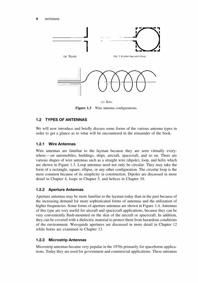
Figure 1.3 Wire antenna configurations.
1.2 TYPES OF ANTENNAS
We will now introduce and briefly discuss some forms of the various antenna types inorder to get a glance as to what will be encountered in the remainder of the book.
1.2.1 Wire Antennas
Wire antennas are familiar to the layman because they are seen virtually every-where—on automobiles, buildings, ships, aircraft, spacecraft, and so on. There arevarious shapes of wire antennas such as a straight wire (dipole), loop, and helix whichare shown in Figure 1.3. Loop antennas need not only be circular. They may take theform of a rectangle, square, ellipse, or any other configuration. The circular loop is themost common because of its simplicity in construction. Dipoles are discussed in moredetail in Chapter 4, loops in Chapter 5, and helices in Chapter 10.
1.2.2 Aperture Antennas
Aperture antennas may be more familiar to the layman today than in the past because ofthe increasing demand for more sophisticated forms of antennas and the utilization ofhigher frequencies. Some forms of aperture antennas are shown in Figure 1.4. Antennasof this type are very useful for aircraft and spacecraft applications, because they can bevery conveniently flush-mounted on the skin of the aircraft or spacecraft. In addition,they can be covered with a dielectric material to protect them from hazardous conditionsof the environment. Waveguide apertures are discussed in more detail in Chapter 12while horns are examined in Chapter 13.
1.2.3 Microstrip Antennas
Microstrip antennas became very popular in the 1970s primarily for spaceborne applica-tions. Today they are used for government and commercial applications. These antennas

TYPES OF ANTENNAS 5
(a) Pyramidal horn
(b) Conical horn
(c) Rectangular waveguide
Figure 1.4 Aperture antenna configurations.
consist of a metallic patch on a grounded substrate. The metallic patch can take manydifferent configurations, as shown in Figure 14.2. However, the rectangular and circularpatches, shown in Figure 1.5, are the most popular because of ease of analysis and fab-rication, and their attractive radiation characteristics, especially low cross-polarizationradiation. The microstrip antennas are low profile, comformable to planar and nonplanarsurfaces, simple and inexpensive to fabricate using modern printed-circuit technology,mechanically robust when mounted on rigid surfaces, compatible with MMIC designs,and very versatile in terms of resonant frequency, polarization, pattern, and impedance.These antennas can be mounted on the surface of high-performance aircraft, spacecraft,satellites, missiles, cars, and even handheld mobile telephones. They are discussed inmore detail in Chapter 14.
1.2.4 Array Antennas
Many applications require radiation characteristics that may not be achievable by asingle element. It may, however, be possible that an aggregate of radiating elementsin an electrical and geometrical arrangement (an array) will result in the desired

6 ANTENNAS
h
h
Ground plane
(a) Rectangular
Patch
Substrate
L
t
W
Ground plane
(b) Circular
ε r
t
Substrateε r
Patch
a
Figure 1.5 Rectangular and circular microstrip (patch) antennas.
radiation characteristics. The arrangement of the array may be such that the radiationfrom the elements adds up to give a radiation maximum in a particular direction ordirections, minimum in others, or otherwise as desired. Typical examples of arraysare shown in Figure 1.6. Usually the term array is reserved for an arrangement inwhich the individual radiators are separate as shown in Figures 1.6(a–c). However thesame term is also used to describe an assembly of radiators mounted on a continuousstructure, shown in Figure 1.6(d).
1.2.5 Reflector Antennas
The success in the exploration of outer space has resulted in the advancement of antennatheory. Because of the need to communicate over great distances, sophisticated formsof antennas had to be used in order to transmit and receive signals that had to travelmillions of miles. A very common antenna form for such an application is a parabolicreflector shown in Figures 1.7(a) and (b). Antennas of this type have been built withdiameters as large as 305 m. Such large dimensions are needed to achieve the highgain required to transmit or receive signals after millions of miles of travel. Anotherform of a reflector, although not as common as the parabolic, is the corner reflector,shown in Figure 1.7(c). These antennas are examined in detail in Chapter 15.

RADIATION MECHANISM 7
ReflectorsDirectors
Feedelement
(a) Yagi-Uda array
(c) Microstrip patch array (d) Slotted-waveguide array
Patch
εr Substrate
Ground plane
(b) Aperture array
Figure 1.6 Typical wire, aperture, and microstrip array configurations.
1.2.6 Lens Antennas
Lenses are primarily used to collimate incident divergent energy to prevent it fromspreading in undesired directions. By properly shaping the geometrical configurationand choosing the appropriate material of the lenses, they can transform various formsof divergent energy into plane waves. They can be used in most of the same applica-tions as are the parabolic reflectors, especially at higher frequencies. Their dimensionsand weight become exceedingly large at lower frequencies. Lens antennas are classi-fied according to the material from which they are constructed, or according to theirgeometrical shape. Some forms are shown in Figure 1.8 [2].
In summary, an ideal antenna is one that will radiate all the power delivered to itfrom the transmitter in a desired direction or directions. In practice, however, suchideal performances cannot be achieved but may be closely approached. Various typesof antennas are available and each type can take different forms in order to achieve thedesired radiation characteristics for the particular application. Throughout the book,the radiation characteristics of most of these antennas are discussed in detail.
1.3 RADIATION MECHANISM
One of the first questions that may be asked concerning antennas would be “how isradiation accomplished?” In other words, how are the electromagnetic fields generated

8 ANTENNAS
Figure 1.7 Typical reflector configurations.
Figure 1.8 Typical lens antenna configurations. (SOURCE: L. V. Blake, Antennas, Wiley, NewYork, 1966).
RADIATION MECHANISM 9
by the source, contained and guided within the transmission line and antenna, andfinally “detached” from the antenna to form a free-space wave? The best explanationmay be given by an illustration. However, let us first examine some basic sourcesof radiation.
1.3.1 Single Wire
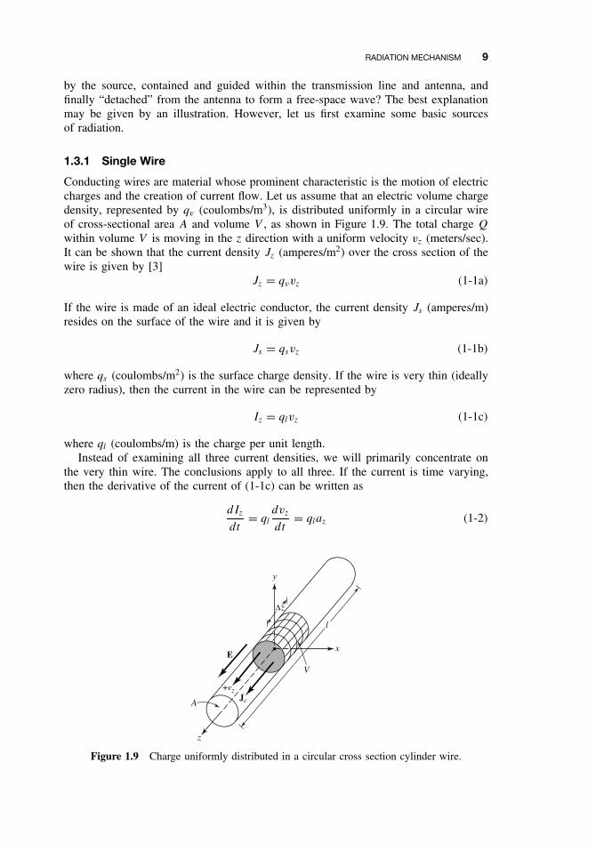
Conducting wires are material whose prominent characteristic is the motion of electriccharges and the creation of current flow. Let us assume that an electric volume chargedensity, represented by qv (coulombs/m3), is distributed uniformly in a circular wireof cross-sectional area A and volume V , as shown in Figure 1.9. The total charge Q
within volume V is moving in the z direction with a uniform velocity vz (meters/sec).It can be shown that the current density Jz (amperes/m2) over the cross section of thewire is given by [3]
Jz = qvvz (1-1a)
If the wire is made of an ideal electric conductor, the current density Js (amperes/m)resides on the surface of the wire and it is given by
Js = qsvz (1-1b)
where qs (coulombs/m2) is the surface charge density. If the wire is very thin (ideallyzero radius), then the current in the wire can be represented by
Iz = qlvz (1-1c)
where ql (coulombs/m) is the charge per unit length.Instead of examining all three current densities, we will primarily concentrate on
the very thin wire. The conclusions apply to all three. If the current is time varying,then the derivative of the current of (1-1c) can be written as
dIz
dt= ql
dvz
dt= qlaz (1-2)
z
x
y
V
A
E
Jc
+vz
∆z
l
Figure 1.9 Charge uniformly distributed in a circular cross section cylinder wire.
10 ANTENNAS
where dvz/dt = az (meters/sec2) is the acceleration. If the wire is of length l, then(1-2) can be written as
ldIz
dt= lql
dvz
dt= lqlaz (1-3)
Equation (1-3) is the basic relation between current and charge, and it also serves as thefundamental relation of electromagnetic radiation [4], [5]. It simply states that to createradiation, there must be a time-varying current or an acceleration (or deceleration) ofcharge. We usually refer to currents in time-harmonic applications while charge is mostoften mentioned in transients. To create charge acceleration (or deceleration) the wiremust be curved, bent, discontinuous, or terminated [1], [4]. Periodic charge acceleration(or deceleration) or time-varying current is also created when charge is oscillating ina time-harmonic motion, as shown in Figure 1.17 for a λ/2 dipole. Therefore:
1. If a charge is not moving, current is not created and there is no radiation.
2. If charge is moving with a uniform velocity:
a. There is no radiation if the wire is straight, and infinite in extent.
b. There is radiation if the wire is curved, bent, discontinuous, terminated, ortruncated, as shown in Figure 1.10.
3. If charge is oscillating in a time-motion, it radiates even if the wire is straight.
A qualitative understanding of the radiation mechanism may be obtained by consid-ering a pulse source attached to an open-ended conducting wire, which may be con-nected to the ground through a discrete load at its open end, as shown in Figure 1.10(d).When the wire is initially energized, the charges (free electrons) in the wire are set inmotion by the electrical lines of force created by the source. When charges are accel-erated in the source-end of the wire and decelerated (negative acceleration with respectto original motion) during reflection from its end, it is suggested that radiated fieldsare produced at each end and along the remaining part of the wire, [1], [4]. Strongerradiation with a more broad frequency spectrum occurs if the pulses are of shorter ormore compact duration while continuous time-harmonic oscillating charge produces,ideally, radiation of single frequency determined by the frequency of oscillation. Theacceleration of the charges is accomplished by the external source in which forces setthe charges in motion and produce the associated field radiated. The deceleration of thecharges at the end of the wire is accomplished by the internal (self) forces associatedwith the induced field due to the buildup of charge concentration at the ends of the wire.The internal forces receive energy from the charge buildup as its velocity is reduced tozero at the ends of the wire. Therefore, charge acceleration due to an exciting electricfield and deceleration due to impedance discontinuities or smooth curves of the wireare mechanisms responsible for electromagnetic radiation. While both current density(Jc) and charge density (qv) appear as source terms in Maxwell’s equation, charge isviewed as a more fundamental quantity, especially for transient fields. Even thoughthis interpretation of radiation is primarily used for transients, it can be used to explainsteady state radiation [4].