anthony liftgates, inc. installation · anthony liftgates, inc. ... check the lowering valve...
TRANSCRIPT

MMOODDEELLSS
MRT-3500
MRT-3500-BH
MRT-3500-GB
MRT-4500
MRT-4500-BH
MRT-4500-GB
MRT-5500
MRT-5500-BH
MRT-6500
MRT-6500-BH
Anthony Liftgates, Inc.
1037 W. Howard Street • P.O. Box 615 • Pontiac, IL 61764-0615
Ph: 815.842.3383 • Fax: 815.844.3612 • Toll Free: 800.482.0003
www.anthonyliftgates.com
Revision 04/08
A N T H O N Y L I F T G A T E S , I N C .
INSTALLATIONAND
OPERATIONFor Magnum RailTrac® Hydraulic Liftgates
KEEP IN VEHICLE WITH LIFTGATE


General Information Section
Introduction . . . . . . . . . . . . . . . . . . . . . . . . . . . . . . . . . . . . . . . . . . . . . . . . . . . . . . . . . . . . . . . . . . 5
Design Features . . . . . . . . . . . . . . . . . . . . . . . . . . . . . . . . . . . . . . . . . . . . . . . . . . . . . . . . . . . . 7
Warranty . . . . . . . . . . . . . . . . . . . . . . . . . . . . . . . . . . . . . . . . . . . . . . . . . . . . . . . . . . . . . . . . . . 8
Decals . . . . . . . . . . . . . . . . . . . . . . . . . . . . . . . . . . . . . . . . . . . . . . . . . . . . . . . . . . . . . . . . . . . . 8
Nomenclature. . . . . . . . . . . . . . . . . . . . . . . . . . . . . . . . . . . . . . . . . . . . . . . . . . . . . . . . . . . . . . . . . 9
General Information . . . . . . . . . . . . . . . . . . . . . . . . . . . . . . . . . . . . . . . . . . . . . . . . . . . . . . . . . . 10
Ordering Parts . . . . . . . . . . . . . . . . . . . . . . . . . . . . . . . . . . . . . . . . . . . . . . . . . . . . . . . . . . . . . 10
Tooling Required . . . . . . . . . . . . . . . . . . . . . . . . . . . . . . . . . . . . . . . . . . . . . . . . . . . . . . . . . . . 10
Installation Section
General Installation Information. . . . . . . . . . . . . . . . . . . . . . . . . . . . . . . . . . . . . . . . . . . . . . . . . 11
Check Shipment. . . . . . . . . . . . . . . . . . . . . . . . . . . . . . . . . . . . . . . . . . . . . . . . . . . . . . . . . . . . 11
Basic Mounting Information . . . . . . . . . . . . . . . . . . . . . . . . . . . . . . . . . . . . . . . . . . . . . . . . . . . 11
Van Body Capacity Ratings . . . . . . . . . . . . . . . . . . . . . . . . . . . . . . . . . . . . . . . . . . . . . . . . . . . 11
Installation of RailTrac Liftgates on Flatbead Trucks. . . . . . . . . . . . . . . . . . . . . . . . . . . . . . . . 12
Prior To Installation . . . . . . . . . . . . . . . . . . . . . . . . . . . . . . . . . . . . . . . . . . . . . . . . . . . . . . . . . 13
Installation Procedure . . . . . . . . . . . . . . . . . . . . . . . . . . . . . . . . . . . . . . . . . . . . . . . . . . . . . . . . . 14
Tack Weld the Liftgate Assembly to the Truck Body . . . . . . . . . . . . . . . . . . . . . . . . . . . . . . . . 14
Weld the Power Pack and Battery Box Enclosures to the Truck Body . . . . . . . . . . . . . . . . . . 17
Make the Electrical and Hydraulic Connections . . . . . . . . . . . . . . . . . . . . . . . . . . . . . . . . . . . 18
Electrical Wiring. . . . . . . . . . . . . . . . . . . . . . . . . . . . . . . . . . . . . . . . . . . . . . . . . . . . . . . . . . . . 21
Check the Operation of the Liftgate. . . . . . . . . . . . . . . . . . . . . . . . . . . . . . . . . . . . . . . . . . . . . 24
Complete the Final Welding . . . . . . . . . . . . . . . . . . . . . . . . . . . . . . . . . . . . . . . . . . . . . . . . . . 26
Cable Lug Installation . . . . . . . . . . . . . . . . . . . . . . . . . . . . . . . . . . . . . . . . . . . . . . . . . . . . . . . 28
Mount the Inside Van Control (Optional) . . . . . . . . . . . . . . . . . . . . . . . . . . . . . . . . . . . . . . . . . 28
Final Inspection Checklist . . . . . . . . . . . . . . . . . . . . . . . . . . . . . . . . . . . . . . . . . . . . . . . . . . . . . 29
Decals . . . . . . . . . . . . . . . . . . . . . . . . . . . . . . . . . . . . . . . . . . . . . . . . . . . . . . . . . . . . . . . . . . . . . . 30
Operation Section
General Safety Operating Instructions . . . . . . . . . . . . . . . . . . . . . . . . . . . . . . . . . . . . . . . . . . . 35
Do’s . . . . . . . . . . . . . . . . . . . . . . . . . . . . . . . . . . . . . . . . . . . . . . . . . . . . . . . . . . . . . . . . . . . . . 35
Don’ts. . . . . . . . . . . . . . . . . . . . . . . . . . . . . . . . . . . . . . . . . . . . . . . . . . . . . . . . . . . . . . . . . . . . 35
Operating Instructions . . . . . . . . . . . . . . . . . . . . . . . . . . . . . . . . . . . . . . . . . . . . . . . . . . . . . . . . 36
Position the Platform for Dock Loading . . . . . . . . . . . . . . . . . . . . . . . . . . . . . . . . . . . . . . . . . . 36
Position the Platform for Loading and Unloading . . . . . . . . . . . . . . . . . . . . . . . . . . . . . . . . . . 37
Position the Platform to the In-Transit Stored Position . . . . . . . . . . . . . . . . . . . . . . . . . . . . . . 38
Maintenance Section
Preventative Maintenance Guide . . . . . . . . . . . . . . . . . . . . . . . . . . . . . . . . . . . . . . . . . . . . . . . . 39
Preventative Maintenance . . . . . . . . . . . . . . . . . . . . . . . . . . . . . . . . . . . . . . . . . . . . . . . . . . . . 39
Monthly Inspection. . . . . . . . . . . . . . . . . . . . . . . . . . . . . . . . . . . . . . . . . . . . . . . . . . . . . . . . . . 40
Semi-Annual Inspection. . . . . . . . . . . . . . . . . . . . . . . . . . . . . . . . . . . . . . . . . . . . . . . . . . . . . . 41
815-842-3383 3 Anthony Liftgates, Inc. (rev. 04-08)
Contents

Maintenance and Troubleshooting Procedures . . . . . . . . . . . . . . . . . . . . . . . . . . . . . . . . . . . . 42
Check the Lowering Valve Cartridge and Coil. . . . . . . . . . . . . . . . . . . . . . . . . . . . . . . . . . . . . 42
Inspect the Cylinder Piston Seals . . . . . . . . . . . . . . . . . . . . . . . . . . . . . . . . . . . . . . . . . . . . . . 42
Check and Adjust the Relief Valve . . . . . . . . . . . . . . . . . . . . . . . . . . . . . . . . . . . . . . . . . . . . . 42
Adjust the Platform Speed. . . . . . . . . . . . . . . . . . . . . . . . . . . . . . . . . . . . . . . . . . . . . . . . . . . . 43
Raise/Lower Flow Control Valve . . . . . . . . . . . . . . . . . . . . . . . . . . . . . . . . . . . . . . . . . . . . . . . 44
Battery Separator. . . . . . . . . . . . . . . . . . . . . . . . . . . . . . . . . . . . . . . . . . . . . . . . . . . . . . . . . . . 44
Safety Section
Safety . . . . . . . . . . . . . . . . . . . . . . . . . . . . . . . . . . . . . . . . . . . . . . . . . . . . . . . . . . . . . . . . . . . . . . 45
Safety is Your Responsibility . . . . . . . . . . . . . . . . . . . . . . . . . . . . . . . . . . . . . . . . . . . . . . . . . . 45
Safety Signal Words . . . . . . . . . . . . . . . . . . . . . . . . . . . . . . . . . . . . . . . . . . . . . . . . . . . . . . . . 45
Safety Rules . . . . . . . . . . . . . . . . . . . . . . . . . . . . . . . . . . . . . . . . . . . . . . . . . . . . . . . . . . . . . . 45
Troubleshooting Section
Troubleshooting Guide . . . . . . . . . . . . . . . . . . . . . . . . . . . . . . . . . . . . . . . . . . . . . . . . . . . . . . . . 48
Attention!
The success or failure of this equipment could very well depend on the proper installation of the liftgate. Readand understand the contents of these instructions before proceeding!
Important
When installed, this liftgate must not alter or prevent vehicle compliance to any existing state or federalstandards and especially FMVSS 108. Each chassis manufacturers recommendations should be consulted forcompliance.
Note to Installers!
Read the operating instructions and maintenance guide before installing the unit to familiarize yourself with itsoperation.
Important Operation Notes
A restraining system may be needed to retain certain types of cargo on the liftgate platform, depending upon thespecific application, such as a cart stop, retention ramp, fencing, straps, etc. This should be considered by thepurchaser for their particular application so as to prevent the possibility of severe personal injury or death dueto cargo shifting and/or falling from the liftgate platform.
All users of this liftgate must be 21 years of age and have read and understood all operation instruction bookletsand decals before use.
Anthony Liftgates, Inc. (rev. 04-08) 4 815-842-3383

Congratulations on selecting an Anthony MagnumRailTrac Liftgate. Anthony liftgates are among thefinest available on the market today. This manualwill provide you with the necessary instructions andsafety precautions to correctly install and operatethe standard, bed height (BH), or gas bottle (GB)models of Anthony Magnum RailTrac liftgate. AParts Manual for this liftgate is available (PDFformat) in the Manuals section of our website atwww.anthonyliftgates.com/manuals.php.
1. Installation, Operation, Troubleshooting, andMaintenance manual for MRT Model MagnumRailTrac Liftgates (AR-IO-04/08).
2. Parts manual for MRT Model Magnum RailTracLiftgates (AR-P-04/08).
(1) Magnum RailTrac Liftgate. (2) Power Unit Enclosure.
(3) Battery Box.
The Magnum RailTrac Liftgate provides up to 58 inches of total lift height. The lifting capacity ofthe Magnum RailTrac Liftgate ranges from 3500 to6500 pounds, depending on the model.
The Magnum RailTrac Liftgate works best on truckbodies with “roll-up” style doors, however it canalso be installed on flat bed trucks. The standard,bed height (BH), and gas bottle (GB) models are allinstalled using the same method. Gas bottleversions are normally installed on flat bed trucksand require the addition of diagonal braces toconnect the rails of the liftgate to the bed of thetruck. These diagonal braces are not part of the kitand must be provided by the installer. Refer to theinstallation instructions for further details.
With the proper tools and two installers, theMagnum RailTrac Liftgate can be installed in four tofive hours (8 to 10 total manhours).
This Installation, Operation, and Maintenancemanual will provide you with easy to followinstructions, along with photos and illustrations.We have included a series of Tips, which willfacilitate the installation process. All Safetyprecautions have been clearly identified anddetailed throughout each section.
In addition to the installation instructions, acomplete explanation of the safety words and rulesare included in the Safety Section of this manual.Please turn to the Safety Section and read itthoroughly before proceeding to the next page.
At the bottom of each page is the Anthony LiftgatesInc. Product Support phone number. If you areunclear about any of the instructions, please phoneAnthony Liftgates' Product Support.
All Anthony Magnum RailTrac model liftgates arefactory assembled, tested, and energized to ensurethe highest quality performance standards. TheMRT model liftgates ship completely assembled forfast, clean, and easy installation.
815-842-3383 5 Anthony Liftgates, Inc. (rev. 04-08)
Introduction
General Information Section

Even though the following goes without saying,we feel compelled to state:
Anthony Liftgates should only be installed by thosewith sufficient skills to understand the installationand operation of the liftgate, along with theequipment required to install the liftgate. Theinstallation instructions in this manual are intendedto give typical installation instructions to the installerfor both the operation and what we believe to bethe most desirable sequence of installation. Theseinstructions cannot replace a qualified person, orclear thinking and the basic knowledge that mustbe possessed by the installer.
We urge the installer (or anyone else) to call us ifthey have any questions. We have qualifiedpersonnel at our Pontiac, Illinois plant to answerany questions that you may have. Sometimes, adetailed discussion on the phone can be far moresatisfactory than a detailed written explanation.
It has been our experience that a knowledgeablejourneyman following these installation instructionsand observing the operation of the liftgate will havesufficient comprehension of the liftgate to enable thisperson to troubleshoot and correct all normalproblems that may be encountered.
However, again we urge you to call us at our Pontiac,Illinois plant if you find the liftgate is not operatingproperly or if you do not know how to make thenecessary repair.
If you have any doubts or questions, call us at:Anthony Liftgates, Inc.1037 West Howard StreetPontiac, Illinois 61764(815) 842-3383Web: w w w . a n t h o n y l i f t g a t e s . c o mEmail: [email protected]
Anthony Liftgates, Inc. (rev. 04-08) 6 815-842-3383
The success or failure of this liftgateto properly and efficiently operate willdepend on a thorough and properinstallation. Failure to read,understand, and follow the installationinstructions and safetyrecommendations in this manualbefore installing the liftgate can resultin serious injury or death. Also readand understand the operatinginstructions in the Operation Section.
When installed, this liftgate must notalter nor prevent vehicle complianceto any existing state or federalstandards, and especially FMVSS 105.Each chassis manufacturer’srecommendations should beconsulted for compliance. Also makesure the weight of the liftgate and itsload will not overbalance the truck,possibly raising the front wheels offthe ground.
N INGAR
DANGER

Design Features
We believe the benefits of the Anthony SERVICE-FREE design are significant. The featuresdesigned into our liftgates ensure LOW operatingcosts, decrease maintenance time, and increaseoperating time; making Anthony Liftgates the bestchoice for rail application liftgates.
Service Free Operation
The MRT liftgate is exclusively designed forService-Free operation. These models have NOgrease zerks, no rollers or roller bearings, and nolifting cables; which are prone to significantmaintenance and sometimes failure.
Dual Pump and Motor
The MRT is equipped with two hydraulic pumps andmotors that operate together, acting as a back-up inthe event one system should stop functioning. Thisfeature allows the driver/operator to continuemaking uninterrupted deliveries for the the rest ofhis/her shift.
In the event one motor stops functioning, the travelspeed of the platform will slow by approximatelyhalf the normal operating speed. On “PowerUp/Gravity Down” models, only the UP speed isaffected. The lowering speed will remain the same.On the “Power Up/Power Down” models, both theUP and DOWN speeds will be reduced by half.
Direct Cylinder Lift
Our liftgate is raised and lowered by two hydrauliccylinders. These cylinders eliminate many normalwear items such as lift chains and bearings. Thecylinders are housed with the H-frame housing.
Gear-Type, Flow Divider
The direct cylinder lift design uses a maintenancefree, non-adjustable, "gear type" flow divider. Webelieve our flow divider has significant benefits overother liftgates which use adjustable "orifice-type"flow divider valves. These other flow dividers areoften difficult to adjust and then hard to maintainproper pressure settings.
The Anthony "gear-type" flow divider balances thefluid between the cylinders within 2% of each other.Our research and testing shows that our "gear-type" flow divider is more accurate and trouble freethan "orifice-type" flow dividers.
Self-Leveling (rephasing)
After installation and during the initial operation ofthe liftgate (with no load), the platform can be out oflevel by approximately one to one and one-halfinches and still be within our specifications. Thiscondition will not harm the liftgate structure orhydraulic components and is corrected with aprocedure known as rephasing.
Rephasing is performed by raising the platform tothe fully raised position. Then, lower the platformabout ten inches and raise it to the fully raisedposition again. Repeat this step several timeswhile holding the Up switch for 5 to 6 seconds eachtime. This allows hydraulic fluid to pass from onelift cylinder to the other until the hydraulic fluid isbalanced on both sides.
After rephasing, the platform should be level withthe truck floor. The platform may become unevenagain, but this is usually caused by air trappedwithin the hydraulic system. The air should workitself out in a short period of time, through normaluse of the hydraulic system.
Cylinder Mounting Swivel Connections
The Anthony MRT liftgates are equipped with ourexclusive "swivel connection" ends on both liftcylinders. These connections are similar to thoseused in the agriculture industry on three-pointtractor hitches. Our design maintains a straightvertical lift force between the two ends of each liftcylinder, even when the platform is out of level.This helps prevent internal damage and scoring ofcylinder pistons and rods.
Our design testing has proven through intentional,out-of-level lifting; that NO damage has occurred toany components of the liftgate, either structural orhydraulic, with even as much as 12 inches of out-of-levelness.
815-842-3383 7 Anthony Liftgates, Inc. (rev. 04-08)

Warranty
IMPORTANT NOTICEThe liftgate must be installed according tothe installation instructions or the warrantywill be void. Unauthorized modifications ofthe liftgate may cause it to improperlyoperate or cause other unforeseenproblems or dangers. If any deviation isdeemed necessary, written permissionmust first be obtained from AnthonyLiftgates.
Before calling for warranty or other productinformation, have the serial number, modelnumber, and lift capacity of your liftgate, which isstamped into the identification plate on thestreetside of the liftgate.
Identification plate.
Refer to the “Limited Warranty” section at the endof this manual for complete warranty details.
Decals
Safety decals provide a vital role in helping toreduce injuries and/or possibly even death. Toensure the greatest level of safety, all decals mustbe in place and legible at all times. Remember, it isthe users responsibility to maintain these decals.For a complete part number list and illustrations ofthese decals, refer to the Decals section on page30 of this manual.
For decal placement, also refer to the Decalssection of this manual.
For replacement decals contact:Anthony Liftgates, Inc.1037 West Howard StreetPontiac, Illinois 61764(815) 842-3383Web: www.anthonyliftgates.comEmail: [email protected]
Anthony Liftgates, Inc. (rev. 04-08) 8 815-842-3383
Make sure all decals are attached to
the liftgate and/or truck and are
legible at all times.
N INGAR
DANGER

815-842-3383 9 Anthony Liftgates, Inc. (rev. 04-08)
Liftgate nomenclature.
Nomenclature
Power unit nomenclature.

Ordering Parts
We manufacturer a quality liftgate that requires verylittle maintenance or repair. However, should a partbreak, become damaged, or worn, ourknowledgeable staff can make sure you receive thepart(s) to put your liftgate back into operation.
Note: The liftgate’s packet of information does notcontain a “parts manual.” The most current and up-to-date parts manuals can be obtained byaccessing our website anytime.
Our website address iswww.anthonyliftgates.comClick on “Manual” and choose a model.
If you do not have access to the internet, or justprefer a printed copy of a manual, we can send oneto you. Call or write our office listed below.
For questions or to order parts, contact:Anthony Liftgates, Inc.1037 West Howard StreetPontiac, Illinois 61764(815) 842-3383Email: [email protected]
Tooling Required
The following is a list of suggested tools that shouldbe used to install the Magnum RailTrac Liftgate.
• Overhead Crane or Forklift
• Mig or Stick Welder
• Heavy-Duty C-Clamps
• Tape Measure
• Level (small, magnetic)
• Open End Wrenches
• Flat Bladed Screwdriver
Anthony Liftgates, Inc. (rev. 04-08) 10 815-842-3383
General Information

Check Shipment
You should have the following items for thisshipment to be complete.
1. Liftgate Assembly2. Power Unit Enclosure
(steel unit containing pump/motor)3. Battery Box
Inside the Power Unit Enclosure box are hoses andfittings, wiring, nuts and bolts, decals, and othermiscellaneous items which will be used to completethe installation. These items are shown on page13.
Basic Mounting Information
The Magnum RailTrac Liftgate models are intendedfor installation on a semi-trailer or the van body of astraight truck.
If a Magnum RailTrac Liftgate model will beinstalled on the van body of a straight truck, re-tighten the U-bolts that secure the van body to thechassis.
Tip: DO NOT attempt to install a Magnum RailTracLiftgate on a flatbed vehicle without consultingthe factory to determine feasibility.
Dimensions of Anthony Liftgates Magnum RailTrac Liftgate.1 Can be removed if other lights are used.
Van Body Capacity Ratings
The Magnum RailTrac Liftgate mounts to the rearcorner posts of the truck body. Before installing theliftgate, make sure each corner can support theload capacities to be placed on them.
MRT-3500 (side walls and corner post)Tension . . . . . . . . . . . . . . . . . . . . . . . . . 2250 lbs.Compression . . . . . . . . . . . . . . . . . . . . . 2250 lbs.Shear . . . . . . . . . . . . . . . . . . . . . . . . . . 3500 lbs.
MRT-4500 (side walls and corner post)Tension . . . . . . . . . . . . . . . . . . . . . . . . . 2800 lbs.Compression . . . . . . . . . . . . . . . . . . . . . 2800 lbs.Shear . . . . . . . . . . . . . . . . . . . . . . . . . . 4500 lbs.
MRT-5500 (side walls and corner post)Tension . . . . . . . . . . . . . . . . . . . . . . . . . 3500 lbs.Compression . . . . . . . . . . . . . . . . . . . . . 3500 lbs.Shear . . . . . . . . . . . . . . . . . . . . . . . . . . . 5500 lbs.
MRT-6500 (side walls and corner post)Tension . . . . . . . . . . . . . . . . . . . . . . . . . 4250 lbs.Compression . . . . . . . . . . . . . . . . . . . . . 4250 lbs.Shear . . . . . . . . . . . . . . . . . . . . . . . . . . . 6500 lbs.
MRT-1003
6"
9.5" .5"
13"
FRONT
REARLIGHT
ASSEMBLY
OVERALL WIDTH OF COLUMNS COLUMN( FRONT TO REAR )
LIGHT GUARD
6"
95.75"
96" to 102"
TRUCKFLOOR LEVEL
1
815-842-3383 11 Anthony Liftgates, Inc. (rev. 04-08)
General Installation Information
Installation Section

Locations of load.
(A) Tension. (B) Compression. (C) Shear. (1) Floor Height.
(2) Top of Column (85 inches). (3) Reinforcing Strap, optional
(3/16 x 4 inch, quantity 2).
Tip: When the strength of the body is in doubt, adda reinforcing strap (3) to the interior of eachside of the vehicle.
Installation of RailTrac Liftgates onFlatbed Trucks
Described below is the installation requirements forthe diagonal bracing used on flatbed truck bodies.Two sets of diagonal braces (two upper and twolower) are required. Diagonal braces can be madefrom the shipping/lift supports or otherrecommended materials.
1. Weld or bolt the liftgate to the truck bed. Referto the normal installation procedure forrecommendations and safety precautions.
2. Weld an upper diagonal brace between the H-frame rail and the truck bed on each side.The ends of the diagonal brace should be aminimum of 42” above the truck bed and aminimum of 42” from the end of the truck bed.
a. Cut two upper diagonal braces from theshipping/lift support or from 2 1/2 x 2 1/2 x 1/4” thick angle iron.
b. Weld each diagonal brace to the H-framerail and to the top of the truck bed.
3. Weld a lower diagonal brace between the H-frame rail and the truck bed on each side.The lower diagonal brace or gusset shouldextend at least one half the length of the rail.For example, if the H-frame rail extends 20”below the truck bed, the ends of the diagonalbrace should extend at least 10” downward and10” inward from the end of the truck bed.
a. Cut two lower diagonal braces from theshipping/lift support or from 2 1/2 x 2 1/2 x 1/4” thick angle iron. A gusset(support plate) can also be made from a 1/4”thick steel plate.
b. Weld each diagonal brace or gusset to theliftgate H-frame rail and to the bottom of thetruck bed.
4. If the truck body corner posts are made fromaluminum, six steel mounting brackets must befabricated and installed on the corner posts.
a. The mounting brackets should be madefrom at least 3/16” thick steel plate. Theeight mounting holes should be for 1/4” boltsor larger. Make the brackets similar to theexample shown in the following drawing.
Dimensions for steel mounting plates.
As required
10"Approx.
3"
3"
3"
1"_21"_
23/16"
thickness min. A-1004
42"(minimum)
A-1046
42"(minimum)
Diagonal bracing is required forall liftgate installations.Install upper and lower diagonalbracing on both sides of the liftgate.
Lower Diagonal BraceUse the shipping/lift support or a minimum of 2½" x 2½" x ¼" angle iron or a ¼" thicksteel plate.Extend this brace at least ½ the distance ofthe rail length.
Upper Diagonal BraceUse the shipping/lift support or a minimum of 2½" x 2½" x ¼"angle iron.
AA
C
C
B
B
A
B
2 3
1
C
MRT-1001
Anthony Liftgates, Inc. (rev. 04-08) 12 815-842-3383
It is the responsibility of the installer(s) tomake sure the steel mounting brackets willsafely hold the liftgate onto the truck. If thesebrackets fail, possible injury or death mayresult.
DANGER

b. Mount the steel brackets to the aluminumcorner posts at the locations shown below.The sill of the truck bed may also requireshims to make sure the surface of themounting brackets and the sill are flush.
Mounting locations for steel mounting brackets.
5. Make sure the corner posts are flush with therear sill. If they are not flush, add spacers, asshown in the illustration.
Add spacers to make the corner posts flush with the rear sill.
Weld spacers to the corner post using 3/16 x 2” long welds
every 12”.
Tip: An alternative to one long spacer is using 3”long plates spaced 9” apart. Make sure thelast plate is located 45” or 61” above the bedheight, depending on the liftgate model beinginstalled.
Prior To Installation
Tip: The power unit box should contain plastic tiewraps for the power cable (1), one 200 Ampcircuit breaker and bracket (2), two shortelectrical cables (3) and two long electricalcables (4), battery tie-down rods and anglebracket (5), clear low-pressure hose (6), andone package containing decals, manuals,low-pressure T-fitting, and three hose clamps(7).
1. Place the truck on a flat, level surface. The rearsurface of the truck or trailer must be straightand square.
2. Block the wheels to prevent possible truckmovement during liftgate installation.
3. Remove the banding securing the power unitenclosure. Remove the loose parts from thepump box.
Tip: The power unit box should contain plastic tiewraps for the power cable (1), one 200 Ampcircuit breaker and bracket (2), two shortelectrical cables (3) and two long electricalcables (4), battery tie-down rods and anglebracket (5), clear low-pressure hose (6), andone package containing decals and manuals(7).
4. Remove all obstructions from the rear of the truckthat would interfere with the operation orinstallation of the liftgate. Obstructions mayinclude, dock bumpers, ICC bumpers, tail lights,door hinges, latches, or any other protrusion.
3/16 x 2" longwelds every 12"
on both sides of therear corner post, on
each side of truck
A-1009
Rear sill and spacer must be flush.
45"
Spacer (thicknessas required)
(61" on above bedheight models)
A-1008
Bed Height
Rear sill and spacermust be flush.
AluminumCorner Post
45" (61" on above bedheight models)
Bed Height
Rear sill and bracketsmust be flush.
A-1005
815-842-3383 13 Anthony Liftgates, Inc. (rev. 04-08)

This section of the manual will guide you throughthe complete installation process, step-by-step. Itis important that you follow all of the instructions inthe sequence we have provided. This sequencewill provide a quicker and easier installationprocess of the liftgate.
The installation process of the liftgate includesthese steps:
Steps 1 - 9Tack weld the liftgate assembly to the truck body.
Steps 10 - 13Weld the power pack and battery box enclosures to
the truck body.
Steps 14 - 37Make the electrical and hydraulic
connections.
Steps 27 - 45Check the operation of the liftgate.
Steps 46 - 51Complete the final welding.
Steps a - hMount the inside van control (optional).
Tack Weld The Lifgate Assembly ToThe Truck Body
Step 1Make sure the proper required bumper (ICC orREAR UNDERRIDE) is in place and meets allFederal Regulations.
Step 2Cut the banding attaching the hoses and wiring tothe liftgate.
Step 3Measure and determine the centerline of theliftgate. Mark this point.
Anthony Liftgates, Inc. (rev. 04-08) 14 815-842-3383
Installation Procedure

Step 4Measure and determine the centerline of the truck’srear sill. Mark this point.
Step 5Use a forklift or hoist to raise the liftgate onto therear of the vehicle. Lay hoses and wires down tothe side of the liftgate where they will not bedamaged.
Tip: Raise the liftgate by the top shipping support,located between the columns.
Step 6Remove the two shipping legs, but do not removebottom cross support.
Step 7
Set the liftgate onto the rear sill of the truck bodyusing the leveling brackets. Do not pinch wires orhoses when positioning the liftgate against thetruck body.
Tip: Two "leveling brackets" are used to positionthe liftgate assembly flush with the truck bodyfloor. The leveling brackets can be removedafter the installation is complete.
815-842-3383 15 Anthony Liftgates, Inc. (rev. 04-08)
Failure to prevent the truck frommoving during the installation of theliftgate could result in seriouspersonal injury or crushing of theinstaller(s).
DANGER
To prevent personal injury, make sure youuse a lifting device to position the liftgateonto the rear sill of the truck.
DANGER
To prevent personal injury or death, DO NOTremove the lifting device until the tackwelding is completed.
DANGER

Step 8
Center the liftgate assembly side-to-side on therear of the vehicle by matching the liftgate and truckbody centerline markings. Hold or clamp thecolumns of the liftgate securely against the rearframe of the vehicle using heavy-duty C-clamp(s)on each side. The columns should now be tight (nogaps) against the full height of the rear frame of thevehicle.
Step 9Tack weld the liftgate to both corner posts of thevehicle. Place the tack welds (8 welds) at the topand bottom (inside and outside) of each column.The tack welds should be a minimum of 3/16 x 2 inches long and capable of holding at least2600 pounds.
The final welding of the liftgate will be completedafter the unit is tested for correct operation.
Anthony Liftgates, Inc. (rev. 04-08) 16 815-842-3383
To avoid personal injury, do not workunder the platform during installation.Work so you are not in the way if alifting device, clamps, welds, etc.should fail.
DANGER
The tack welds must be strong enough tohold the weight of the liftgate. Insufficientwelds may not hold the liftgate in place,resulting in bodily harm.
CAUTION
Weld The Power Pack and BatteryBox Enclosures To The Truck Body
We recommend installing the power unit enclosure(30 inches long) and the battery enclosure (27 inches long) on the curbside of the vehicle forsafety purposes, such as when service is requiredon the road.
Typically the units are mounted behind the rearwheels (behind the furthest rear wheel on a trailer).However, if the space will not allow both units to beinstalled side by side, the power units can be infront of the rear wheels, or one unit on either sideof the rear wheels as shown in this manual.Mounting the power unit enclosure in front of thewheels may require a hose and wiring extension kit(contact Anthony factory for an extension kit).
The hoses and wires supplied with the power unitsallow it to be mounted approximately 10 to 12 feetfrom the rear of the vehicle. Before welding the unitto the frame, make sure the hoses and wires willreach the enclosure box.
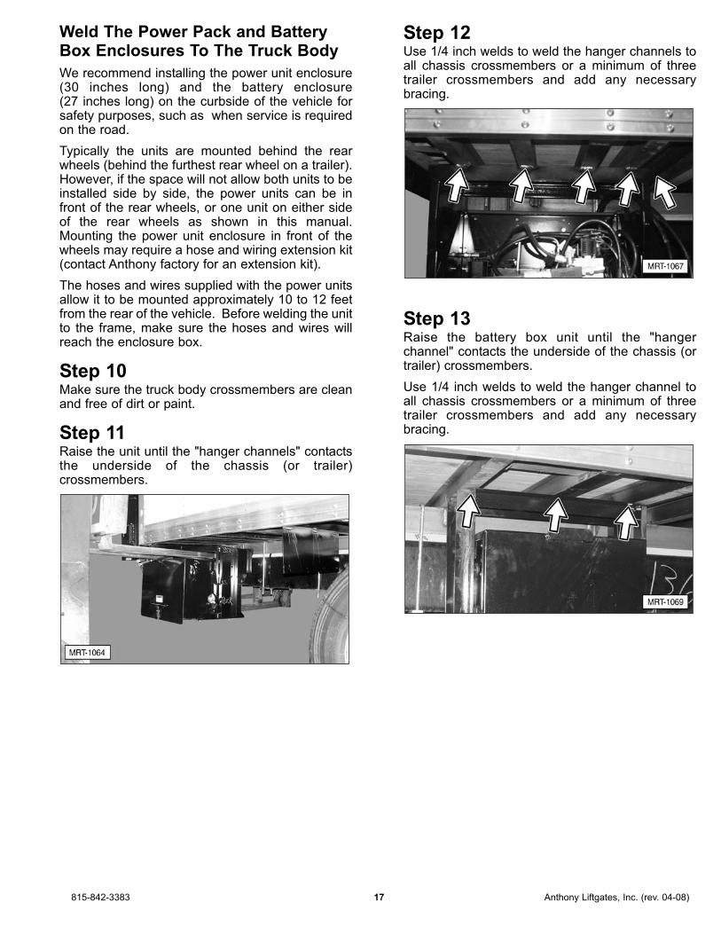
Step 10Make sure the truck body crossmembers are cleanand free of dirt or paint.
Step 11Raise the unit until the "hanger channels" contactsthe underside of the chassis (or trailer)crossmembers.
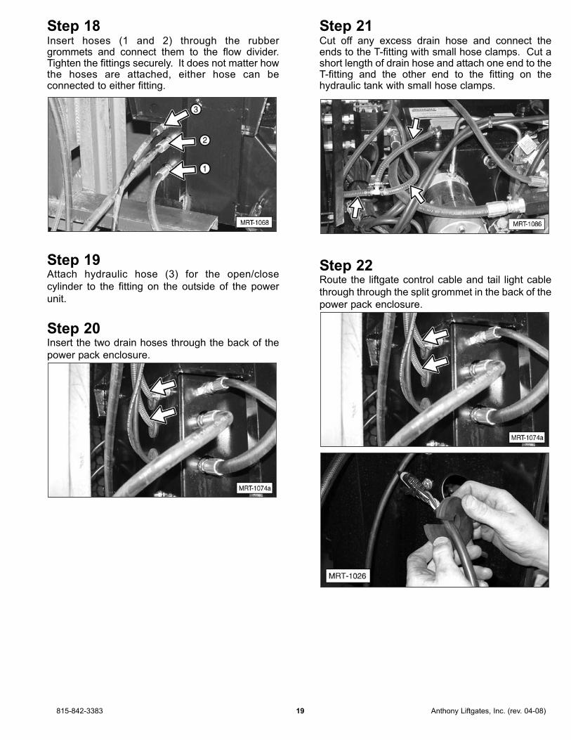
Step 12Use 1/4 inch welds to weld the hanger channels toall chassis crossmembers or a minimum of threetrailer crossmembers and add any necessarybracing.
Step 13Raise the battery box unit until the "hangerchannel" contacts the underside of the chassis (ortrailer) crossmembers.
Use 1/4 inch welds to weld the hanger channel toall chassis crossmembers or a minimum of threetrailer crossmembers and add any necessarybracing.
815-842-3383 17 Anthony Liftgates, Inc. (rev. 04-08)

Make The Electrical And HydraulicConnections
Three hydraulic hoses and one breather hose runfrom the liftgate to the power unit enclosure.
Step 14Route the street side high-pressure hose, low-pressure hose, and electrical wire through or underthe crossmembers and along the frame to thepower unit. Also route the curbside hoses and wireto the power unit.
Step 15Remove the cap from the fitting and the plug fromhose. Connect the hose to the fitting and tighten itsecurely.
Shown with optional batteries.
Step 16Remove the two caps from the flow divider,indicated by the arrows.
Step 17Remove the plugs from the end of each hydraulichose.
NOTE: This unit has been hydraulically tested atthe factory and the hoses are filled with oil. Takecare when removing the plugs not to drain oil fromthe hoses, as this will create an air bubble withinthe hose.
Anthony Liftgates, Inc. (rev. 04-08) 18 815-842-3383
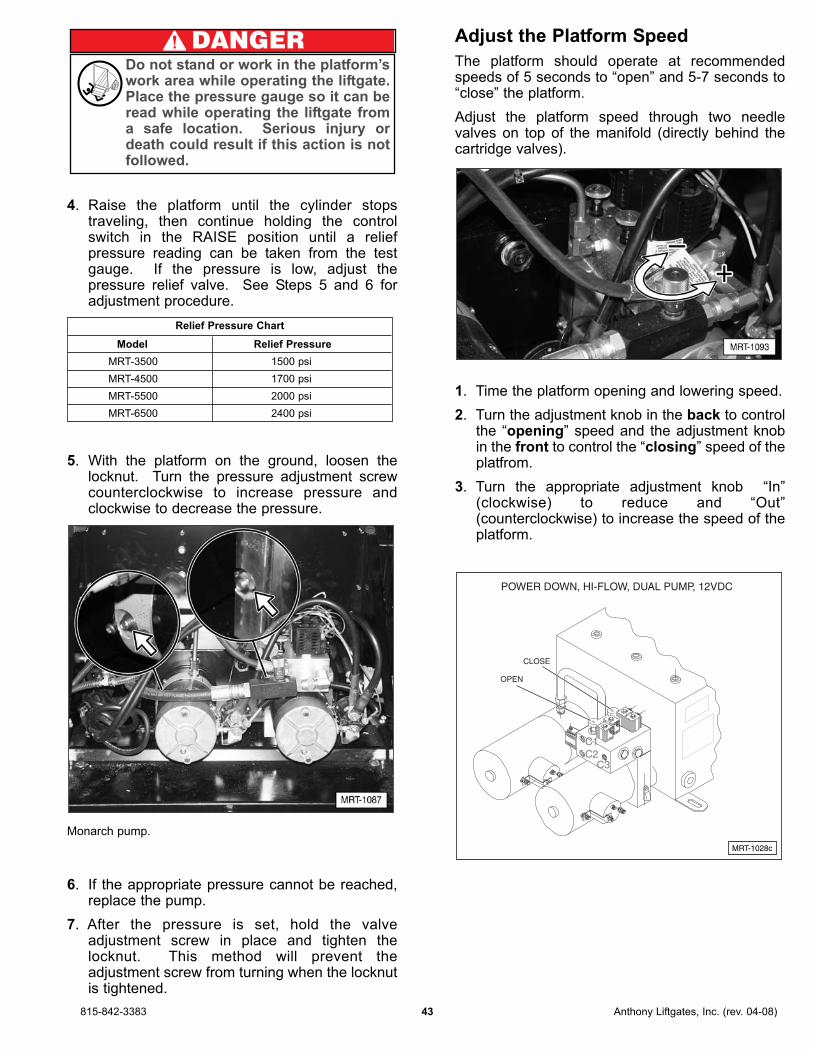
Step 18Insert hoses (1 and 2) through the rubbergrommets and connect them to the flow divider.Tighten the fittings securely. It does not matter howthe hoses are attached, either hose can beconnected to either fitting.
Step 19Attach hydraulic hose (3) for the open/close
cylinder to the fitting on the outside of the power
unit.
Step 20Insert the two drain hoses through the back of the
power pack enclosure.
Step 21Cut off any excess drain hose and connect theends to the T-fitting with small hose clamps. Cut ashort length of drain hose and attach one end to theT-fitting and the other end to the fitting on thehydraulic tank with small hose clamps.
Step 22Route the liftgate control cable and tail light cable
through through the split grommet in the back of the
power pack enclosure.
815-842-3383 19 Anthony Liftgates, Inc. (rev. 04-08)

Step 23Connect the liftgate control cable, which controls all
the liftgate functions (up, down, open, and close) to
its mating connection inside the power pack
enclosure.
Step 24Connect the liftgate tail light cable, which controls
the running lights, backup lights, and brake lights,
to its mating connection inside the power pack
enclosure.
Step 25Use clamps or plastic ties (provided) to secure thehoses and wires to the crossmembers,approximately every three feet.
Anthony Liftgates, Inc. (rev. 04-08) 20 815-842-3383

Electrical Wiring
NOTE: The battery supply cable may need to becut to various lengths to connect the power pack,the batteries in the liftgate battery box, and thevehicles batteries. For information on properlycrimping battery lugs onto the cable, refer to theCable Lug Installation section in this manual.
NOTE: This installation uses two 12 Volt dedicatedbatteries located in a separate battery box. Thisconfiguration requires two circuit breakers. Onecircuit breaker is customer installed near thevehicle’s battery box. The other circuit breaker isinstalled in the power unit enclosure and ispreconnected to the On/Off power switch. Thesecircuit breakers provide the liftgate with protectionagainst anything that may contact the batteryterminals or other situations that could cause anelectrical short. The circuit breakers are able tocarry up to 200 Amps. The two circuit breakers inthis application will protect the "charge” cablebetween the liftgate batteries and the truckbatteries.
815-842-3383 21 Anthony Liftgates, Inc. (rev. 04-08)
CUT OFF
POWER UNIT
(TRUCK) BATTERY(IES)TRACTOR OR
CIRCUIT
+ -
ALTERNATIVE METHOD
SWITCH
MOUNTED INPUMP BOX
POWER CABLE
MOUNTED WITHIN
2 FT. OF BATTERY
BREAKER
(RELOCATED FROM LIFTGATE PUMP BOX)
TOWARD FRONT OF VEHICLE
EXISTING
#1 OT
GROUND
GROUND
12 VOLTW/ BRACKET200 AMP
MRT-1038
+ -
+ -
+ -
CUT OFF
POWER UNIT
LIFT GATE BATTERIES
CIRCUIT BREAKERCIRCUIT BREAKER
RECOMMENDED METHOD
SWITCH
PUMP BOX BATTERY BOX
TRUCK'S BATTERY BOX
POWER CABLE
2 FT. OF BATTERY)
(MOUNTED WITHIN
OPTIONAL
(TRUCK) BATTERY(IES)
EXISTINGTRACTOR OR#2 OT
GROUND
GROUND
GROUND
12 VOLT
12 VOLT
12 VOLT
200 AMP
200 AMPW/ BRACKET

Step 26Make sure the power unit cut-off switch is in the Offposition.
Step 27Route a ground cable (wire supplied with kit)through the back of the power unit enclosure.Connect one end to the pump body (A) and theother the frame (B).
Step 28Route the battery supply cable (wire supplied withkit) through the back of the power unit enclosure.Connect one end to the On/Off switch (C).
Anthony Liftgates, Inc. (rev. 04-08) 22 815-842-3383

Step 29Route the cable to the battery box and connect theend to the 200 Amp circuit breaker terminal (D).
Step 30Route the long battery cable through the right sideof the battery box and connect it to the positive (+)terminal (E) of the battery.
Step 31Route the other end of the battery cable from theliftgate battery box the vehicle’s battery box.
Step 32Install 200 Amp Circuit Breaker (1) somewherenear or in the truck battery compartment (within 24 inches), where it is easy to reach to be reset.
NOTE: An optional battery separator can also beinstalled at this time. The following steps cover theinstallation of the battery separator. If this option isnot used, connect the battery cable from the liftgatebattery box to circuit breaker terminal (H).
815-842-3383 23 Anthony Liftgates, Inc. (rev. 04-08)

Step 33Connect the battery cable from the liftgate batterybox to terminal (F) on the battery separator orterminal (H) of the circuit breaker.
Step 34Connect battery separator terminal (G) to circuitbreaker terminal (H).
Step 35Connect circuit breaker terminal (I) to the batteriespositive (+) post (J).
Step 36Connect a #14 gauge wire between chassis groundand the battery separator ground terminal. Thismay momentarily activate the battery separator.This is normal. For additional wiring options, referto the Battery Separator section in this manual.
Step 37Make sure all hoses and wires are securelyattached to the frame of the vehicle. Make surethat no wire or hose will be damaged by rubbingagainst another part.
Check The Operation Of The Liftgate
The standard Magnum RailTrac Liftgate operatesas a power up (close) and gravity down (open) unit.It can also be ordered to operate as a power up(close) and power down (open) unit, which providespower when lowering.
Step 38Press and hold the Up/Down switch in the Upposition until the platform raises up off the top of the"latches" (this will be approximately 1/8 inch ofupward movement).
Step 39Press and hold the Open/Close switch in the Closeposition until the closer cylinders remove thetension from the platform off the latch bars (or untilyou see the platform close a little).
Anthony Liftgates, Inc. (rev. 04-08) 24 815-842-3383
Make sure the area where the platform will befunctioning (up, down, open, and close) isfree of obstructions and people beforeoperating the liftgate.
CAUTION

Step 40Remove and discard the middle shipping supportthat attaches to both columns, just above the lights.
Step 41Release the "runner latches," one on the outside ofeach column, by moving the lever handle forward.
Step 42Press the Down switch to lower the platform(approximately 8 inches) until the platform latchblocks clear the column latch bars.
Tip The Magnum RailTrac Liftgate has a safetycatch feature on the platform latches, whichengage if the closer cylinder loses hydraulicpressure. The latch blocks on the platform flipsection will catch the latch bars as it is lowered(approximately 4 inches down). Raise theplatform and fold the platform closed, whichshould allow the platform to lower withoutopening unintentionally.
Step 43Press the Open switch to unfold the platform.
Step 44Raise and lower the platform to make sure itoperates without binding. Air introduced into thesystem during installation will work itself out afterseveral cycles of normal operaton.
815-842-3383 25 Anthony Liftgates, Inc. (rev. 04-08)

Step 45If the liftgate has been successfully operatedthrough its cycle, remove and discard the uppershipping support.
Complete The Final Welding
Thoroughly check the position of the liftgateassembly before starting the final welding.
1. The liftgate must be centered on the chassisor trailer.
2. The crossmember must be flush with thefloor.
3. Both columns must be tight against the rearframe.
4. The columns must be square with thevehicle body and parallel to each other.
If any of these items is not correct, reposition theliftgate.
Step 46Complete the final welding.
Weld the liftgate columns to the rear frame of thechassis or trailer using seven, equally spaced 3/16"wide by 2" long welds (A) down both sides (insideand outside) of each column (28 total welds).
Tip: Do not over weld the outside of the columns,because too much heat can damage thehoses and wires inside the columns.
A
MRT-1006
Anthony Liftgates, Inc. (rev. 04-08) 26 815-842-3383

Step 47Weld the floor extension crossmember to thechassis or trailer rear sill using seven, equallyspaced 3/16" wide by 2" long welds across the topedge of the floor extension crossmember.
Step 48Connect the liftgate tail light connector to thevehicle tail light cable. Make sure the connection iswatertight.
Step 49Attach the license plate and license plate light tothe chassis (or trailer) below the level of the truckfloor using the original bracket.
Step 50Attach all decals, as shown in the Decal section ofthis manual.
Step 51Complete the Final Inspection Checklist section.
815-842-3383 27 Anthony Liftgates, Inc. (rev. 04-08)

Cable Lug Installation
1. Strip insulation one inch back from the end ofthe cable to expose the copper wire.
Remove one inch of insulation.
2. Position the cable lug on the exposed wire, asshown. Crimp the cable lug using a cablecrimping tool (hydraulic or manual).
Install cable lug.
IMPORTANT NOTICEProper wire connections are crucial to thelife of the liftgate’s power unit. DO NOTsmash the cable lug with a hammer tosecure it to the cable. Poor connectionscan result in low voltage, and any attemptto operate below the minimum requiredvoltage could result in system failure.
3. Use the supplied heat shrink tube to insulate thenew connection. Heat the shrink tubing using aheat gun or propane torch until it shrinks aroundthe cable insulation and cable lug, leaving onlythe mounting hole exposed. DO NOT overheatthe heat shrink tubing.
Put heat shrink tubing over connection.
Mount The Inside Van Control(Optional)
The inside van control (optional) will allow anoperator to raise and lower the liftgate from insidethe trailer. The inside van control is designed tomount in the plywood lining of the trailer (up to 1/4 inch thick).
Tip: If the plywood lining is more than 1/4 inchthick, "spot face" the plywood lining or cut outa bigger hole and mount cup into a thin pieceof metal.
a. Place the inside van control approximately 3 feet above the floor of the trailer or at yourdesired location.
b. Drill a 2-1/4 inch diameter hole through theplywood lining for the recessed switch plate.
c. Drill a 1/2 inch hole in the bottom rail of the sidewall, directly below the switch location.
d. Feed the electrical cord inside the side wall andthrough the hole in bottom rail.
e. Secure the recessed plate and switch to theplywood lining with 3 wood screws.
f. Route the electrical cord through (or under) thevehicle crossmembers and tie any dangling cordto the vehicle.
g. Route the electrical cord into the power unitenclosure and connect the wires into theterminal strip by matching the wire numbers.
Tip: The white wire in the UP/DOWN controlshould be attached to the small post on themotor-start solenoid.
h. After connections are completed, close thepump enclosure door and secure the latch.
A-1012
TYPE SGT
TYPE SGT
A-1011
TYPE SGT
TYPE SGT
TYPE SGT
TYPE SGT
A-1010
1"
Anthony Liftgates, Inc. (rev. 04-08) 28 815-842-3383

❏❏ Check all welds to make sure they are doneproperly.
❏❏ Make sure all pins are in place and held withproper retainers.
❏❏ Make sure the power unit reservoir is filled.
• Power Down model – The fluid level shouldbe visible in the reservoir sight glass when theliftgate platform is in the unfolded andRAISED position.
❏❏ Fill the hydraulic fluid reservoir.
Use Mobile Multi-purpose ATF hydraulic oil orequivalent. For cold weather operation, werecommend Mobile 1 Synthetic ATF.
If an emergency situation occurs, then anautomotive transmission fluid such as Dexron IIcan be used.
NOTICEDO NOT thin hydraulic fluid with brakefluid, and DO NOT use brake fluid in placeof hydraulic fluid.
❏❏ Close the cover on the power pack enclosureand battery box. Make sure they are securedwith a padlock, lock pin, or wire (customersupplied).
❏❏ Make sure the platform is properly adjusted withthe necessary shims required to make it level.
❏❏ Operate the liftgate through its entire operationalcycle (Up, Down, Open, and Close) severaltimes. Make sure the liftgate operates evenly,freely, and smoothly throughout the entireoperating range and that there is no unusualnoise or vibration while operating the liftgate.
❏❏ Make sure the platform is operating at therecommended speeds of 5 seconds for“opening” and 5-7 seconds for “closing”. If not,refer to the Maintenance section for instructionson adjusting the speed of the platform.
❏❏ Make sure all decals are in place and legible.
❏❏ Make sure the license plate bracket is properlyinstalled, as required by law.
❏❏ Make sure the truck and/or trailer meets all local,state, and federal regulations; including, but notlimited to those required for bumpers, lighting,and reflectors.
❏❏ Put the Installation, Operation, and Maintenancemanual in the glove compartment of the vehicle.
815-842-3383 29 Anthony Liftgates, Inc. (rev. 04-08)
Final Inspection Checklist
Do not use the liftgate if any of the items inthe Final Inspection Checklist are notchecked and verified. If you have anyquestions, contact your nearest Anthonydistributor, or the Anthony Liftgates mainoffice.
DANGER

Safety decals provide a vital role in helping toreduce injuries and/or possibly even death. Toensure the greatest level of safety, all decals mustbe in place and legible at all times. Remember, it isthe users responsibility to maintain these decals.For a complete part number list of the decals usedon the Magnum RailTrac Liftgates, refer to theDecals section in the Parts manual.
For replacement decals contact: Anthony Liftgates, Inc.1037 West Howard StreetPontiac, Illinois 61764(815) 842-3383Web: w w w . a n t h o n y l i f t g a t e s . c o mEmail: [email protected]
All decals must be in place and legible or allwarranties are void.
1. SF-Series Decal (A-131003)
2. Operating Instructions Decal (A-176566)
3. Latch Decal (A-131017)
4. Maximum Capacity Decal
5500 lbs (A-131015)
3500 lbs. (ATU-177)
4500 lbs. (A-131024)
5500 lbs. (A-131010)
6500 lbs. (A-131025)
5. Urgent Warning Decal (Q-003013)
6. Danger: Clearance Decal (A-146982)
7. Runner Latch Decal (A-131006)
8. After Using Liftgate Decal (ATU-141)
9. Caution: PinchPoint Decal (AR-18-76)
10. Serial Number Plate
11. Weld Warning Decal (A-131028)
12. Electrical Overload Decal (A-150238)
13. Anthony Decal (A-131013)
14. Stand Clear Do Not Ride Decal (ATU-146)
15. Zero Leak Concept Decal (A-131026)
Anthony Liftgates, Inc. (rev. 04-08) 30 815-842-3383
Decals
Make sure all decals are attached to
the liftgate and/or truck and are
legible at all times.
N INGAR
DANGER

1. A-131003
2. A-176566
3. A-131017
A-131017 03/2008A-131003 03/2008
R
815-842-3383 31 Anthony Liftgates, Inc. (rev. 04-08)
A-176566 03/2008

4.
5. Q-003013
IMPORTANT NOTICEMake sure the proper “maximum capacity” decalgoes on the appropriate liftgate. For example, the“5500 Maximum Capacity” decal goes on MRT-5500 models only. Do not put a higher rated decal(6500 pound) on a smaller liftgate (model 5500);this could result in liftgate damage or possiblypersonal injury. 3500 lb. - ATU-1774500 lb. - A-1310245500 lb. - A-1310106500 lb. - A-131025
A-131010 03/2008
Anthony Liftgates, Inc. (rev. 04-08) 32 815-842-3383
Q-003013 03/2008
WARNING

6. A-146982
7a. A-131006
7b. A-131044(For use on Bed-Height Models.)
8. ATU-141
9. AR-18-76
10. Serial Number Plate
11. A-131028
AR-18-76 03/2008
ATU-141 03/2008
A-131044 03/2008
A-131006 03/2008
A-146982 03/2008
815-842-3383 33 Anthony Liftgates, Inc. (rev. 04-08)

12. A-150238
13. A-131013
14. ATU-146
15. A-131026
16. A-131030
A-131030, Rev. A 03/2008
A-131026 03/2008
Manufactured with ZLC
Zero
Leak
Concept
Another First from Anthony Liftgates, Exclusively!
™
™
ATU-146 03/2008
THIS LIFTGATE IS PROTECTEDWITH AN ELECTRICAL OVERLOAD
CIRCUIT BREAKER, LOCATED NEARTHE POWER SUPPLY.
NOTICE
A-150238 03/2008
Anthony Liftgates, Inc. (rev. 04-08) 34 815-842-3383

The following is a list of Do’s and Don’ts for theoperation of the liftgate.
✔✔ Do’s
✔ Read and follow warning decals, operatingdecals, and owners manual(s).
✔ Keep all decals in place and legible and retainthe owners manual(s) in the vehicle or allWarranties are void.
✔ Make sure the vehicle is properly and securelybraked before using the liftgate.
✔ Keep yourself clear of all moving parts.
✔ Make sure the area where the platform will befunctioning (up, down, open, and close) is free ofobstructions and people before operating theliftgate.
✔ Make sure the platform area, including the areain which loads may fall from the platform, is clearbefore, during, and at all times while operatingthe liftgate.
✔ Always place the load as close to the center ofthe platform as possible. Also, position the loadas close to the center of the truck’s rear sill aspossible.
✔ Make sure the slide runners move smoothlyinside the H-frame columns with no unusualnoise or vibration.
✔ Only operate the liftgate with the Up/Downcontrol mounted on the H-frame column or usingan optional, inside van control.
✔ Follow a complete, thorough lubrication andmaintenance schedule as directed by thismanual.
✔ Check the oil level in the hydraulic tank monthly.Change the oil if it is dirty or contaminated usingMobil Multi-Purpose ATF. For cold weatheroperation, we recommend Mobil 1 Synthetic ATF.
✔ Visually inspect your liftgate frequently and keepit properly adjusted.
✔ Visually inspect the platform chains and replacethem if signs of wear or damage are present.
✔ Repair any damage to the liftgate to preventaccidents.
✔ Place the liftgate into the storage position withthe platform latched when the liftgate is not inuse.
✘✘ Don’ts
✘ Do not overload the platform. The maximumrated capacity is based on an evenly distributedload on the platform’s flat surface.
✘ Do not ride on the liftgate. Always stand clear ofthe liftgate when it is operating.
✘ Do not allow children to play around or operatethe liftgate.
✘ Do not allow your liftgate to be used by personsnot familiar with its operation.
✘ Do not crash your liftgate into loading docks orother objects which can inflict serious damage tothe liftgate.
✘ Do not use your liftgate if it shows signs of abuseor fails to operate freely and smoothly.
✘ Do not allow the motor/pump to run after theliftgate is fully raised and has stopped moving.
✘ Do not use brake fluid in the hydraulic reservoir.
✘ Do not bounce the platform by pushing andreleasing the control button/switch abruptly.
✘ Do not use the liftgate for anything other than itsintended use of loading and unloading cargo.
✘ Do not operate lift trucks on or over any part ofthe platform.
✘ Do not stand under or place any object under theliftgate work area.
✘ Do not drive the truck unless the liftgate is in thestored position and the platform latches aresecured.
815-842-3383 35 Anthony Liftgates, Inc. (rev. 04-08)
General Safety Operating Instructions
Operation Section
Do not stand in the platform’s workarea while operating the liftgate.Serious injury or death could result ifthe load shifts or is unstable on theplatform.
DANGER

Position the Platform for DockLoading
1. Turn ON the main power to the liftgate. Theswitch is located on the side of the trailer withthe power unit enclosure or in the cab.
2. Disengage the runner latches located on theouter side of each column.
3. Press the “Down” switch to lower the liftgateplatform straight down until the platform is belowthe truck floor.
4. Reverse Steps 1 through 3 to return the liftgateto the in-transit storage position.
Anthony Liftgates, Inc. (rev. 04-08) 36 815-842-3383
Operating Instructions

Position the Platform for Loading
and Unloading
1. Turn ON the main power to the liftgate. Theswitch is located on the side of the trailer withthe pump box or in the cab.
2. Disengage the runner latches located on theouter side of each column.
3. Press the “Down” switch to lower the liftgateplatform straight down, approximately 8 inchesuntil the platform clears the platform latcheslocated on the inner rear edge of the columns.
Tip The Magnum RailTrac Liftgate has a safetycatch feature on the platform latches, whichengage if the closer cylinder loses hydraulicpressure. The latch blocks on the platform flipsection will catch the latch bars as it is lowered(approximately 4 inches down). Raise theplatform and fold the platform closed, whichshould allow the platform to lower withoutopening unintentionally.
4. Press the “Open” switch to unfold the platform.
5. Press the “Up” or “Down” switch to raise orlower the platform.
815-842-3383 37 Anthony Liftgates, Inc. (rev. 04-08)

Position the Platform to theIn-Transit Stored Position
1. Make sure the platform is clear of all objects andevery one is clear of moving parts of the liftgateplatform.
2. Position the platform approximately 8 inchesbelow the floor of the truck.
3. Press the “Close” switch to fold the liftgateplatform. Make sure the platform folds intoproper position for raising.
4. Press the “Up” switch to raise the liftgate into theplatform latches.
5. Engage the runner latches located on the outerside of each column.
6. Turn the liftgate control switch to “Off.”
Anthony Liftgates, Inc. (rev. 04-08) 38 815-842-3383

Preventative Maintenance
Preventative maintenance is one of the most costeffective practices that any equipment owner canimplement. Taking approximately 15 minutes ofyour time to inspect the Magnum RailTrac canresult in hundreds and even thousands of dollars insavings. These savings can come from:
— Increased operating time (no unscheduledbreakdowns at someone’s loading dock).
— Normal wear items will last longer because theyhave been properly maintained and lubricated.
— Less chance of someone becoming injured dueto parts that may fail because of mistreatment orabuse.
Preventative maintenance inspections should onlybe completed with qualified mechanical personnel.In no way are these steps intended to encourageusage or service of the liftgate by anyone who isnot qualified to do so. The overall performance ofthe liftgate is directly related to the skill andknowledge of the mechanic performing theinspection. If the mechanic cannot see potentialproblems, or is unaware of the signs of potentialproblems, the inspection procedure may be a costlywaste of time.
Anthony Liftgates, Inc. 39 815-842-3383
Maintenance Section
Preventative Maintenance Guide
Do not attempt to maintain the liftgatewithout fully understanding all of ourinstructions and safety precautions. Do notattempt to maintain a liftgate unless you haveread and understand all of the instructionsand warnings in the Installation, Operation,and Maintenance manual. If any doubt orquestion arises about the correct or safemethod of performing anything found in thisor other Anthony Liftgates’ manuals, contactyour Anthony Liftgates’ dealer or call theInside Sales and Service representatives atour main headquarters. Proper care is yourresponsibility.
To prevent injury, only qualified mechanicalpersonnel who are aware of and/or able tounderstand the signs of potential problemsshould maintain the liftgate.
DANGER

Monthly Inspection
Preventative maintenance should be performed ona monthly schedule or any time the unit showssigns of improper/abnormal operation or abuse.Following these steps helps to ensure maximumoperator safety and your overall performancesatisfaction.
This inspection procedure starts at the front of thetruck and works its way back to the liftgate. Makesure the vehicle is securely braked beforeperforming any of the following steps.
1. Check the truck’s battery.
❏ Make sure the cells of the battery are properlyfilled.
❏ Check the battery for cracks, leaks, or otherobvious damage.
❏ Make sure the battery hold-down clamp issecurely tightened.
❏ Make sure the liftgate power cable connection istight.
❏ Remove any corrosion, dirt, or grease from thebattery terminals and/or wire connections.
❏ Periodically replace the old battery. (Do not letthe battery fail and then replace it.)
2. Check the circuit breakers to make sure theconnections are tight. One circuit breaker islocated in the truck’s battery box and the otheris in the liftgate’s battery box. Check the powercut-off switch to make sure it disables the powerto the power unit when it is turned to the offposition.
3. Check the power cable from the truck batteryback to the liftgate power unit.
❏ Make sure all connections are free of dirt andcorrosion.
❏ Make sure all connections are tight.
❏ Make sure the entire length of the power cableis not cut or damaged.
4. Inspect the power pack enclosure and batterybox for damage.
❏ Remove any buildup of dirt or debris.
❏ Make sure all the rubber grommets are installedin the access holes through the side of the box.This prevents damage to wires and hoses fromrubbing against the metal surface of theenclosure.
5. Inspect the batteries in the battery boxenclosure using the inspection checks in Step 1.
6. Check the electrical and hydraulic connectionsinside the power pack enclosure and the batterybox.
❏ Check all control wires for corrosion and makesure they have tight connections. Whenreplacing connectors use only Heat ShrinkTerminals.
❏ Check the electrical connections to the startersolenoids.
❏ Check all hydraulic hoses and fittings for fluidleaks. Tighten the fittings to stop leaks orreplace them if they are damaged.
❏ Check the condition of the hydraulic hoses.Replace them if they show signs of leakage orexcessive abrasion of the covering.
7. Check the fluid level in the power unit hydraulictank. Fill the tank as required with Mobile Multi-purpose ATF hydraulic oil or equivalent. Forcold weather operation, we recommend Mobile1 Synthetic ATF.
IMPORTANT NOTICEUse only Mobil Multi-Purpose ATF hydraulicoil or equivalent in the power unit reservoir.For cold weather operation, we recommendMobil 1 Synthetic ATF. Do not use brakefluid.
8. Inspect the hoses and control wires comingfrom power unit to the liftgate.
❏ Check for signs of leaks or chaffing on theoutside covering of the hoses and wiring.
❏ Make sure the wires are securely fastened to thetruck body and not hanging loose where theycould be damaged.
❏ Remove any build-up of dirt and debris from thehoses and wires.
9. Make sure the liftgate is operating properlythrough the complete opening and closingcycle. Before operating the liftgate, make surethe area is free of all obstacles, obstructions, orpeople. Also, if the liftgate is equipped with apower cut-off switch, turn the switch to On.
❏ Check for any clearly visible damage that wouldprevent the liftgate from operating properly.
❏ Make sure both the streetside and curbsiderunner latches release.
❏ Check the control switches for corrosion, dirtbuild-up, or damage.
❏ Check for unusual noises or vibration as theliftgate operates.
Anthony Liftgates, Inc. (rev. 04-08) 40 815-842-3383

❏ Check for any mechanical interference in theslide runners or as the platform opens.
❏ Make sure the liftgate operates freely andsmoothly throughout its entire range ofmovement (up, down, open, and close).
❏ Make sure the platform is level when raised tobed height.
❏ Make sure the platform can be lowered straightdown (below dock level) for dock loading.
10. Inspect the liftgate.
❏ Inspect the liftgate for damage (bent platformmembers or slide runners, cracked welds, etc).
❏ Check all the fasteners on pins, brackets, etc.to make sure those parts are securely held inplace.
❏ Check the platform chains and connectionpoints. Make sure they are in good shape andthe ends are connected properly.
❏ Inspect the retention ramp and make sure itworks properly.
❏ Oil the platform hinge points.
11. Inspect the slide runners.
❏ Clean any build-up of grime or dirt off of theslide runners (power wash if necessary).
❏ Check both mechanical and hydraulicconnections to the cylinders.
❏ Check for any excessive wear or gouging ofslide pads.
❏ To decrease the effects of road salt, roadgrime, and dirt on the slide runners, you canclean the slides and runners with a powerwasher.
❏ Lubricate the slide runners. You can apply"Pam" cooking spray or other spray cooking oilto rejuvenate slides for smoother operation.
12. Check for hydraulic fluid leaks at all threecylinders, (one closing and two lifting) alongthe path of the hydraulic hoses, and in thepower unit enclosure. Replace the hoses ifthey show signs of excessive abrasion orleakage. Tighten any hydraulic fittingsshowing signs of leakage and replace anyhydraulic fittings which are damaged.
13. Examine all Warning, Capacity, andOperational Decals. If they are not readablethey should be replaced. New replacementdecals can be obtained from Anthony Liftgates,Inc.
14. Place the liftgate in the stored position and turnoff the power cut-off switch after each useand/or inspection.
15. If you find anything that shows signs ofexcessive wear or damage, replace that partand any mating parts that may also bedamaged.
If you have any doubts or questions about yourqualifications to operate or maintain the liftgate, callus at:Anthony Liftgates, Inc.1037 West Howard StreetPontiac, Illinois 61764(815) 842-3383Web: w w w . a n t h o n y l i f t g a t e s . c o mEmail: [email protected]
Semi-Annual Inspection
In addition to the items requiring monthlyinspection, also inspect the pump and motor.
1. Disconnect the power cable from the battery.
2. Remove the motor’s end cover.
3. Examine the armature brushes for wear.Brushes should be replaced if they are less than1/8 inch long.
4. Clean out any dirt or debris from inside of themotor housing.
5. Apply several drops of lightweight machine oil tothe armature shaft bearing in the motor endcover and re-assemble the motor.
6. If the oil in the hydraulic tank is dirty, drain the oiland flush the entire system. Refill the systemwith the recommended oil outlined in Step 7 ofthe “Monthly Inspection” section.
815-842-3383 41 Anthony Liftgates, Inc. (rev. 04-08)

Check the Lowering Valve Cartridgeand Coil
1. Place the platform on the ground in the openposition.
2. Place a steel screwdriver over the top of thelowering valve cartridge coil.
3. Momentarily activate the control switch in theDOWN position. The screwdriver should beattracted to the magnetic field created by thecoil.
4. If there is no magnetism, determine if there ispower from the control switch to the coil. If thereis no power, determine if the switch is bad or ifthe problem is in the wire from the switch to thecoil. If there is power to the coil, but it has nomagnetism, then the coil is bad and should bereplaced. If the coil is good, check the loweringvalve cartridge for proper operation.
5. Remove the coil from the lowering valvecartridge assembly.
6. Remove the lowering valve cartridge from thepump body.
7. Clean the lowering valve cartridge and blow itdry with compressed air (not greater than 30 psi). Also, blow out the pump body.
8. Use a small screwdriver and carefully press onthe poppet inside the lowering valve cartridge.The poppet is spring loaded and should movewhen it is pressed. If the poppet does not move,then the lowering valve cartridge should bereplaced.
Inspect the Cylinder Piston Seals
Inspect the cylinder piston rod seals for drifting,caused by seal leakage.
1. Remove the breather hose, if equipped.
2. Raise the platform all the way up and hold theswitch in the “ON” position while checking for oilcoming out of the breather port to the cylinder.
3. If a continuous flow of oil comes out of this port,while the platform is all the way up and theswitch is held “ON”, then the piston seals areleaking and the cylinder should be rebuilt orreplaced.
If the cylinder is under warranty, do not rebuild. Thecylinder will be replaced.
Check and Adjust the Relief Valve
For Magnum RailTrac Liftgates there are two reliefvalves for setting pressure, one on each of the twopump/motors.
To check the pressure setting:
1. Place the platform on the ground and removethe pressure hose from the port on the pump.
2. Install a tee (customer supplied) into the port.
3. Connect a pressure gauge to the tee (with acapacity rating of 4000 psi or above) andreconnect the hydraulic hose. The pressuregauge should be connected to a hose thatallows the mechanic to read the gauge withoutbeing near the platform.
Anthony Liftgates, Inc. (rev. 04-08) 42 815-842-3383
Maintenance and Troubleshooting Procedures
4. Raise the platform until the cylinder stopstraveling, then continue holding the controlswitch in the RAISE position until a reliefpressure reading can be taken from the testgauge. If the pressure is low, adjust thepressure relief valve. See Steps 5 and 6 foradjustment procedure.
5. With the platform on the ground, loosen thelocknut. Turn the pressure adjustment screwcounterclockwise to increase pressure andclockwise to decrease the pressure.
Monarch pump.
6. If the appropriate pressure cannot be reached,replace the pump.
7. After the pressure is set, hold the valveadjustment screw in place and tighten thelocknut. This method will prevent theadjustment screw from turning when the locknutis tightened.
Adjust the Platform Speed
The platform should operate at recommendedspeeds of 5 seconds to “open” and 5-7 seconds to“close” the platform.
Adjust the platform speed through two needlevalves on top of the manifold (directly behind thecartridge valves).
1. Time the platform opening and lowering speed.
2. Turn the adjustment knob in the back to controlthe “opening” speed and the adjustment knobin the front to control the “closing” speed of theplatfrom.
3. Turn the appropriate adjustment knob “In”(clockwise) to reduce and “Out”(counterclockwise) to increase the speed of theplatform.
C2C1
C3
POWER DOWN, HI-FLOW, DUAL PUMP, 12VDC
MRT-1028c
OPEN
CLOSE
815-842-3383 43 Anthony Liftgates, Inc. (rev. 04-08)
Do not stand or work in the platform’swork area while operating the liftgate.Place the pressure gauge so it can beread while operating the liftgate froma safe location. Serious injury ordeath could result if this action is notfollowed.
DANGER
Relief Pressure Chart
Model Relief Pressure
MRT-3500 1500 psi
MRT-4500 1700 psi
MRT-5500 2000 psi
MRT-6500 2400 psi

Raise/Lower Flow Control Valve
Depending on several factors, such as oil viscosity(thickness) and ambient temperature, the raiseand/or lower speed of the liftgate platform mayneed to be adjusted.
1. To increase the lifting and lowering speed turnthe knob on valve counterclockwise.
2. To decrease the speed, turn the knob clockwise.
Battery Separator
The optional battery separator is designed for usein MRT application as a solenoid priority system toprotect the chassis charging system fromexcessive loading while allowing the liftgatebatteries to be charged. The battery separator hastwo basic operational characteristics:
Protect The Charging System
The battery separator monitors the battery systemto determine if the batteries are being charged.When the engine or liftgate batteries reach 13.2 Volts, indicating charging is taking place, thebattery separator will engage, joining the twobattery banks. If the drain on the charging systemby the liftgate batteries or main battery bankreduces the system voltage below 12.8 Volts, thebattery separator will disconnect the batteries fromeach other, thus protecting the respective batterybanks from excessive drain.
A delay function has been incorporated in thecontrol circuit to prevent the battery separator fromreacting to momentary voltage fluctuations andchattering.
Assist In Engine Starting
When the starter is activated the battery separatorcompares the voltage of both battery banks. If thevehicle’s battery is lower than the liftgate batteries,the battery separator will engage allowing theliftgate batteries to aid in vehicle starting. The startsignal must be at least three volts for the operationto occur.
The priorities are to assist in engine starting, ifrequired, and to protect the charging system fromexcessive power drain.
Auxiliary Start Connection (optional)
Automatic operation. Connect a #14 gauge wirefrom the start position of the ignition switch to theStart terminal of the battery separator. Make thisconnection at the ignition switch. This wire shouldonly have voltage when the ignition switch is in thestart position.
NOTE: The start signal must be able to produce atleast 3 Volts in order to provide automatic boost,see connection diagram above for manualoperation option.
NOTE: The auxiliary start function should activatethe battery separator if the main battery voltage islower than the auxiliary battery. The start terminalmust see at least 3V* to activate. The auxiliarybattery must read at least 10 Volts.
Lamp Connections (optional)
Connect a #14 gauge wire from the lamp terminalof the battery separator to one end of an indicatorlamp (250 mA maximum current draw). Connectthe opposite end of the lamp to the chassis ground.This lamp will illuminate when the auxiliary startfunction is activated.
Checking Operation
The battery separator should now be operational.Start the vehicle or apply a charge to the mainbattery. Once the main battery rises to 13.2 Voltsthe battery separator should activate. Turn off thevehicle or remove the charge to the main battery.The battery separator should disconnect theauxiliary battery once the voltage on the mainbattery drops below 12.8 Volts.
LiftgateBattery
MainBattery
To Power Pack
Momentary BoostSwitch Mount
on Dash
AuxilliaryStart
IndicatorLight
For Automatic OperationConnect to Start Position ofIgnition Switch (see step 8)
Auxilliary Start ActivationOptional Connections
For Manual OperationConnect as Shown Here
MainLoads
MRT-1095
Anthony Liftgates, Inc. (rev. 04-08) 44 815-842-3383

Safety is Your Responsibility
It is the responsibility of any individual who installs,maintains, or operates this equipment to fullyunderstand and follow proper operatingprocedures.
Be aware of the inherent dangers in the use of thisproduct and the tools used to install it.
Read and understand all Dangers, Warnings,Cautions, and Important Notices in this manual andon the liftgate or truck.
Safety Signal Words
A signal word or words call attention to the safetysign and designate a degree or level of hazardseriousness. The signal words for AnthonyLiftgates’ product safety signs are DANGER,WARNING, CAUTION, and IMPORTANT NOTICE.
DANGER: Indicates an imminently hazardoussituation which, if not avoided, will result in death orserious injury. This signal word is limited to themost extreme situations.
WARNING: Indicates a potentially hazardoussituation which, if not avoided, could result in deathor serious injury.
CAUTION: Indicates a potentially hazardoussituation which, if not avoided, may result in minoror moderate injury. It may also be used to alertagainst unsafe practices.
IMPORTANT NOTICEIndicates that equipment or propertydamage can result if instructions are notfollowed.
Safety Rules
CAUTION
DANGER
DANGER
815-842-3383 45 Anthony Liftgates, Inc. (rev. 04-08)
Safety Section
Safety
To avoid personal injury or death,carefully read and understand allinstructions pertaining to the AnthonyLiftgates product.
DANGER
Do not attempt to install, operate, or maintainour product without fully understanding allour instructions and safety precautions. Donot operate or work on a truck or liftgateunless you read and understand theinstructions and warnings in the Installation,Operation, and Maintenance manual. If anydoubt or question arises about the correct orsafe method of performing anything found inthis or other Anthony Liftgates’ manuals,contact your Anthony Liftgates’ dealer or callthe Inside Sales and Service representativesat our main headquarters. Proper care isyour responsibility.
To prevent injury, the liftgate should only beinstalled by a qualified installer havingknowledge and skill in using weldingequipment and a cutting torch.
DANGER

Anthony Liftgates, Inc. (rev. 04-08) 46 815-842-3383
Always weld in a well ventilated areaand, if in an enclosed area, vent thefumes to the outside. Breathingwelding smoke and paint fumes cancause serious injury.
Always follow all State and Federalhealth and safety laws and/or localregulations when using an arc welder,mig welder, or cutting torch. Also, followall manufacturers’ safety guidelines. Ifother people are present during theinstallation of the liftgate, make sure thewelding area is shielded from their view.This will help prevent serious eye injuryfrom the bright light.
To avoid eye injury during welding,always wear a welding helmet with theproper lens to shield your eyes fromthe bright light.
Failure to prevent the truck frommoving during the installation of theliftgate could result in seriouspersonal injury or crushing of theinstaller(s).
DANGERTo prevent injury, make sure all decalsare attached to the liftgate and/ortruck and are legible at all times.
To prevent serious bodily injury, keepsparks, lighted matches, and openflames away from the top of thebattery, because battery gas canexplode. Always follow all themanufacturers’ safetyrecommendations when workingaround the truck’s battery.
Take precautions to avoid sparkscoming into contact with the truck’sfuel tank, brake lines, or otherflammable components. Sparks cancause an explosion of combustiblematerials, resulting in serious injuryor death.
Never secure the power cable toanything which allows it to contactsharp edges, other wiring, fuel tank,fuel lines, brake lines, air lines,exhaust system, or any other objectthat could cause the power cable towear or be damaged. A cut batterycable can cause sparks resulting inloss of vehicle control, serious injury,or even death.
N INGAR
DANGER

815-842-3383 47 Anthony Liftgates, Inc. (rev. 04-08)
To avoid personal injury, do not workunder the platform. Failure to safelysecure the liftgate to the truck bodyduring installation could result inserious personal injury. Do notremove the lifting device(s) until theliftgate is completely welded onto thetruck.
To prevent personal injury, clean upany spilled fluids immediately.
To avoid tripping, do not leave toolsor components laying around in thework area.
Do not place hands or feet in pinchpoints.
Do not ride on the platform.
Do not place your feet under theplatform.
Always use/set the truck’s parkingbrake before operating the liftgate.Failure to follow this recommendationcan result in injury.
Most accidents involving theoperation, maintenance, or repair ofproducts made by Anthony Liftgatesoccur because the installer/owner/operator failed to observe basic safetyrules or operating instructions.
WARNING
Take precautions to avoid weldingsparks or the flame from a cuttingtorch coming into contact with thetruck bed’s wooden floor or otherflammable components.
Tack welds must be strong enough tohold the weight of the individualcomponents being held in place.Insufficient tack welds may not holdthe parts in place, resulting inpossible bodily harm.
CAUTION
Many liftgate models provide steps fordrivers as a convenience feature. Whensteps are present, customer-supplied grabhandles and other ingress/egress itemsshould be installed.
Even though the Anthony Liftgate is easy toinstall, the installation should be done with atleast two people.
CAUTION
Accidents can often be avoided by being alertand recognizing potentially hazardoussituations. Any individuals installing,operating, maintaining, or repairing productsmanufactured by Anthony Liftgates shouldhave the necessary training, skills, and toolsrequired to perform these functions properlyand safely. The safety information in thismanual serves as a basic guide in an attemptto prevent injury or death.
Anthony Liftgates cannot anticipate everypossible circumstance that might involve apotential hazard. The warnings in thismanual and on the product itself are,therefore, not all inclusive. If tools,procedures, work methods, or operatingtechniques that are not specificallymentioned by Anthony Liftgates are used,you must satisfy yourself that they are safefor you and for others. Make sure the liftgateor truck it is mounted onto will not bedamaged or made unsafe by any operation,lubrication, maintenance, or repairprocedures that you choose.
DO NOT proceed, if any doubt arises aboutthe correct or safe method of performinganything found in this or other AnthonyLiftgates’ manuals. Seek out expertassistance from a qualified person beforecontinuing.
WARNING
IMPORTANT NOTICEUse only Mobil Multi-Purpose ATFhydraulic oil or equivalent in the powerunit reservoir. For cold weatheroperation, we recommend Mobil 1Synthetic ATF. Do not use brake fluid.
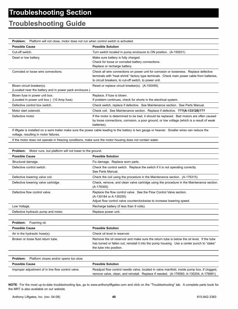
Problem: Platform will not close, motor does not run when control switch is activated.
Possible Cause Possible Solution
Cut-off switch. Turn switch located in pump enclosure to ON position. (A-150031)
Dead or low battery. Make sure battery is fully charged.
Check for loose or corroded battery connections.
Replace or recharge battery.
Corroded or loose wire connections. Check all wire connections on power unit for corrosion or looseness. Replace defective
terminals with “heat shrink” factory type terminals. Check main power cable from batteries,
to circuit breakers, to cut-off switch, to power unit.
Blown circuit breaker(s). Reset or replace circuit breaker(s). (A-150495)
(Located near the battery and in power pack enclosure.)
Blown fuse in power unit box. Replace, if fuse is blown.
(Located in power unit box.) (10 Amp fuse) If problem continues, check for shorts in the electrical system.
Defective control box switch. Check switch, replace if defective. See Maintenance section. See Parts Manual.
Motor start solenoid. Check coil. See Maintenance section. Replace if defective. ???(A-133128)???
Defective motor. If the motor is determined to be bad, it should be replaced. Bad motors are often caused
by loose connections, corrosion, a poor ground, or low voltage (which is a result of weak
batteries).
If liftgate is installed on a semi trailer make sure the power cable leading to the battery is two gauge or heavier. Smaller wires can reduce the
voltage, resulting in motor failures.
If the motor does not operate in freezing conditions, make sure the motor housing does not contain water.
Problem: Motor runs, but platform will not lower to the ground.
Possible Cause Possible Solution
Structural damage. Fix damage. Replace worn parts.
Defective control switch. Check the control switch. Replace the switch if it is not operating correctly.
See Parts Manual.
Defective lowering valve coil. Check the coil using the procedure in the Maintenance section. (A-176315)
Defective lowering valve cartridge. Check, remove, and clean valve cartridge using the procedure in the Maintenance section.
(A-176305)
Defective flow control valve. Replace the flow control valve. See the Flow Control Valve section.
(A-130184 or A-130255)
Adjust flow control valve counterclockwise to increase lowering speed.
Low Voltage. Recharge battery (if less than 9 volts).
Defective hydraulic pump and motor. Replace power unit.
Problem: Foaming oil.
Possible Cause Possible Solution
Air in the hydraulic hose(s). Check oil level in reservoir.
Broken or loose fluid return tube. Remove the oil reservoir and make sure the return tube is below the oil level. If the tube
has turned or fallen out, reinstall it into the pump housing. Use a center punch to “stake”
the tube into position.
Problem: Platform closes and/or opens too slow.
Possible Cause Possible Solution
Improper adjustment of in line flow control valve. Readjust flow control needle valve, located in valve manifold, inside pump box..If clogged,
remove valve, clean, and reinstall. Replace if needed. (A-176560, A-130204, A-176681)
NOTE: For the most up-to-date troubleshooting tips, go to www.anthonyliftgates.com and click on the “Troubleshooting” tab. A complete parts book for
the MRT is also available on our website.
Anthony Liftgates, Inc. (rev. 04-08) 48 815-842-3383
Troubleshooting Section
Troubleshooting Guide

Problem: Motor runs, but platform will not raise, will not raise rated capacity, or raises but drifts down when control switch is released.
Possible Cause Possible Solution
Load capacity has been exceeded. Verify load capacity and adjust load weight.
Structural damage. Replace damaged parts.
Low fluid level. Fill reservoir (with the platform completely lowered to the ground).
Low Voltage. Inspect the battery connection terminals and check the battery’s Voltage
(9 Volts minimum).
Dirty or defective lowering valve. Coil or cartridge may need cleaning or replacement. See Maintenance section.
Bad piston seals. See Maintenance section for Checking Cylinder for Leakage.
Pump relief valve needs adjusted. See Maintenance section for Checking and Adjusting System Pressure.
Hydraulic pump is worn. Replace hydraulic pump.
Air in hydraulic lines. Fill reservoir to within 1/2’ of full with platform on ground with Pennzoil Arctic hydraulic fluid
factory recommended. Use Dextron II ATF as an alternative if Pennzoil is not available.
Power down models fill to 1/2’ of full with platform raised.
Cylinder piston seals blown, allowing fluid to leak Remove breather hose from end of cylinder. Activate power unit to raise position, if
past piston when trying to raise platform. hydraulic fluid pumps out of breather port, repack or replace cylinder. (If under warranty,
replace cylinder - DO NOT repack or dismantle. (A130181)
Lowering valve stuck partially or fully open. With platform on ground, remove lowering valve and inspect. Clean if dirty. Replace if
plunger not freely moveable. (A-176305)
Problem: Platform will not open.
Possible Cause Possible Solution
Platform is still latched. Release the runner latches on each rail.
Blown circuit breaker. Check all connectors and connections for worn or loose parts, replace any worn terminals
with “heat shrink” factory terminals. (A-150495)
Reset circuit breaker.
In line fuse blown. Replace blown fuse with ATO or ATC fuse (10 Amp).
Bad opening valve coil. Remove coil from cartidge and test magnetism of inside of coil with metal object
(screwdriver) while energizing down control side of switch only. (A-176316)
Clogged or bad opening valve on power unit. Remove valve, clean and inspect. If plunger will not move freely, replace. (A-176305)
Problem: Platform lowers slower than normal.
Possible Cause Possible Solution
Improper oil in hydraulic reservoir. Change it to multi-viscosity hydraulic fluid. See Monthly Inspection section.
(Pennzoil Arctic, or Dextron II if not available.)
Damaged or kinked hydraulic hose. Repair or replace hose. See Parts Manual for part numbers.
Cylinder rod is scored, pitted, or bent. Repair or replace cylinder rod. See Parts Manual for part numbers.
Defective flow control valve. Readjust flow control valve (inside pump box, in line of hydraulic hose). One valve is for
open and close speed, the other is for lowering speed.
Replace the flow control valve. See the Flow Control Valve section.
(A-130184, A-130255)
Slide runners or wear strips are dirty, damaged, Clean columns and oil slide runners with 30W motor oil. Replace slide runners or wear
or need oil. strips if they are bent or damaged. See Parts Manual for part numbers.
Clogged or defective lowering valve. Coil or cartridge may need cleaning or replacement. See Maintenance section.
(A-176305)
Problem: Platform raises partially and stops.
Possible Cause Possible Solution
Load capacity has been exceeded. Verify load capacity and adjust load weight.
Structural damage. Replace damaged parts (lift chains, sprockets, slides, cylinder, etc.).
Low Voltage. Recharge battery (if less than 9 volts).
Low pressure. Refill reservoir. Check pump and motor.
815-842-3383 49 Anthony Liftgates, Inc. (rev. 04-08)

Problem: Platform will not close completely.
Possible Cause Possible Solution
Power unit relief valve set too low on liftgate. Loosen lock nut and turn alien screw clockwise to increase pressure. Turn in all the way,
then back out one full turn, retighten lock nut, test liftgate with load. If liftgate performs
well, set pump pressure according to factory settings.
Twisted paltform hinge pin (hex pin). Check to see if twisted by lowering platform below column to see hex pin. Check
alignment of hex pin and lower cylinder pin, should be in between the 8 o’clock and
9 o’clock position with platform open. If not, replace by sawing pin in half and removing
pin and bushings. Replace hex pin and both hex bushings.
(S-070011 or ATU-344, A176457, A-176481, A-176482)
Closure cylinder defective. Repack or replace cylinder. If under warranty, replace cylinder. DO NOT repack or
dismantle. (A-176430, A-176626)
Problem: Platform will not close at all, motor does run.
Possible Cause Possible Solution
Bad cartridge valve coil. Remove coil from cartidge and test magnetism of inside of coil with metal object
(screwdriver) while energizing down control side of switch only. (A-176316)
Closer valve stuck in the closed position. With platform on the ground, remove closing valve, clean and inspect. If plunger not
moving freely, replace valve. (A-176304)
Anthony Liftgates, Inc. (rev. 04-08) 50 815-842-3383

815-842-3383 51 Anthony Liftgates, Inc. (rev. 04-08)
Anthony LIftgates, Inc.Magnum Railtrac Hydraulic Liftgate Inspection Record
Date of Inspection Notes, observations, maintenance performed, etc.

Limited Warranty
Magnum RailTrac
3 yrs Mechanical + 3 yrs Electric/Hydraulic
Thank you for purchasing an Anthony liftgate. Westrive to produce the most trouble free and reliableliftgates in the market. We believe you willexperience years of reliable operation andminimum downtime interruptions. To further insureyour confidence in Anthony, this warranty will coveryour unit for 3 years or 8,000 cycles (whicheveroccurs first) on mechanical/structure, electrical, andhydraulic operating parts. This warranty isextended to the original purchaser (user only) andis not transferable. The warranty term begins fromthe date of shipment from our factory orwarehouse.
Anthony Liftgates Inc. will cover all failedcomponents during the warranty period. Labor willbe provided under our Flat Rate WarrantySchedule, in effect at the time of the part failure,and includes diagnosis time. Contact Anthony forcurrent reimbursement amounts. For repairs NOTlisted on the Flat Rate Warranty Schedule, contactthe Anthony Warranty Department for approvedreimbursement, prior to performing repairs.Anthony Liftgates Inc. reserves the right ofdetermination of whether a component is defectiveor has failed. This warranty applies to Anthonyliftgates installed, operated, and maintained inaccordance with Anthony Liftgates Inc. installation,operation, and maintenance manuals, videos, etc.
Certain Anthony models have published LifetimeWarranties on listed components, as published incurrent literature. This additional coverage will bedetailed on the published operation components,providing the unit has been operated andmaintained within the intended usage.
Anthony Liftgates, Inc. will process all claims anddetermine their eligibility for authorization upon thereceipt of the failed part, the identification of theclaimant, and the liftgate serial number. All partsmust be returned freight prepaid and following theinstructions given by the Anthony WarrantyDepartment. Freight collect shipments will not beaccepted.
PLEASE NOTE THAT NO CLAIMS WILL BEPROCESSED WITHOUT THE PART, THECLAIMANT’S INFORMATION, AND THELIFTGATE SERIAL NUMBER.
Claims not submitted within 30 days of repair datewill be denied.
NOTE: ALL CLAIMS MUST BE COMPLETED ONTHE ANTHONY LIFTGATES INC. WARRANTYCLAIM FORM.
This form provides all the necessary information.
Upon approval of the claim, Anthony will, at thedirection of the claimant, return a replacement partand labor allowance, or a parts credit based oncurrent distributor net pricing, and the appropriateflat rate labor allowance.
Anthony Liftgates, Inc. is not responsible or liablefor loss of time, cost, labor, material, profits, director indirect damages caused by failed components,whether due to rights arising under purchase,order, contract of sale or independently thereof,and whether or not such claim is based on contract,tort, or warranty. The sale of products of AnthonyLiftages, Inc. under any other warranty orguarantee express or implied is not authorized.This warranty does not cover misuse, abuse,damage, or product finish, normal wear,maintenance adjustments, careless or negligenceof use or maintenance. Modifications to ourproduct are not covered unless prior authorized byAnthony.
Purchased Parts warranty is 1 year from date ofpurchase and covers replacement of part only.
If you require assistance or have questions, pleasecontact Anthony Liftgates Inc. at 815-842-3383.
NOTE: Most (not all) Anthony liftgate modelsincorporate our Service-Free feature. Service-Freerefers to the fact that these models require noroutine or scheduled lubrication of the major pivotpoints that contain our service-free bushings.Normal repair and maintenance of your liftgate, perour instruction, is necessary for ALL Anthonyliftgates.
Anthony Liftgates, Inc.1037 W. Howard St. P.O. Box 615Pontiac, IL 61764-0615
PH: 815-842-3383FAX: 815-844-3612E-Mail: [email protected]
Anthony Liftgates, Inc. (rev. 04-08) 52 815-842-3383

Warranty Policy and Procedure
All warranty claims must be completed on theAnthony Liftgates Warranty Claim Form utilizing theFlat Rate Warranty Schedule. See the currentrates as listed for each model. Using this processwill allow for quick and accurate credit payment.
Claims will not be processed without the failed partreturned (pre-paid) to Anthony Liftgates, and thewarranty claim form completed.
NOTE: When returning defective parts for warrantyconsideration, be sure to call ahead for a ReturnAuthorization Number.
If you require further assistance or have questions,please contact the Anthony Liftgates WarrantyDept. at 815-842-3383 or [email protected].
815-842-3383 53 Anthony Liftgates, Inc. (rev. 04-08)

Anthony Liftgates, Inc. (rev. 04-08) 54 815-842-3383

815-842-3383 55 Anthony Liftgates, Inc. (rev. 04-08)

Form No. MRT-IO-04/08
Anthony Liftgates, Inc.1037 W. Howard Street • P.O. Box 615 • Pontiac, IL 61764-0615Ph: 815.842.3383 • Fax: 815.844.3612 • Toll Free: 800.482.0003www.anthonyliftgates.com