anti-lock brake system - lil evo hyundai elantra 16v... · general 58a-3 system component the...
TRANSCRIPT
ANTI-LOCKBRAKESYSTEMReturn To Main Table of ContentsGENERAL ................................................................... 2ABS MODULATOR AND ABS RELAY ........................ 9ABSCM (ABS Control Module) ............................. 11WHEEL SPEED SENSOR .......................................... 12BLEEDING OF BRAKE SYSTEM ................................. 14TROUBLESHOOTING ............................................... 1 5

GENERAL
GENERALSPECIFICATIONS
ABSCM (Anti-Lock Brake System Control Module)Operating voltage rangePower consumptionController fuseOperating temperature range
ABS Service Reminder IndicatorPower consumptionService Reminder Indicator fuse
ModulatorOperating voltage rangeRated voltagePump Motor fuseSolenoid fuseOperating temperature range
9.0-16.2V150 mA or below10A-40o to +80oC
1.2W10A
9.0-16.2V12V30A20A-40°C to 120°C
TIGHTENING TORQUE N.m kg.cm Ib.ft
Sensor mounting bolt on the brake plateFrontRear
Hydraulic unit mounting boltHydraulic unit mounting bracket boltSix brake tubes on the Hydraulic Unit
7-11 70-110 5-817-26 170-260 12-1917-26 170-260 12-1917-26 170-260 12-1913-17 130-170 9-12

GENERAL 58A-3
SYSTEM COMPONENT
The Anti-Lock Brake System (ABS) controls the hydraulic brake pressure of all four wheels during sudden braking andbraking on hazardous road surfaces, preventing the wheels from locking. The ABS provides the following benefits:
(1) Enables steering around obstacles with a greater degree of certainty even during panic braking(2) Enables stopping during panic braking while allowing stability and steerability to a minimum, even on curves.
In case a malfunction occurs, a diagnosis function and fail-safe system have been included for serviceability.
58A-4 GENERAL
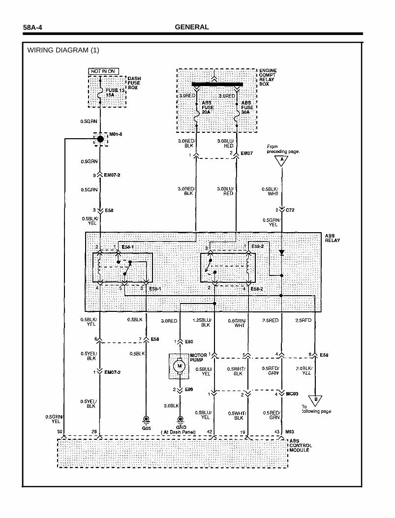
WIRING DIAGRAM (1)

GENERAL 58A-5
WIRING DIAGRAM (2)
GENERAL
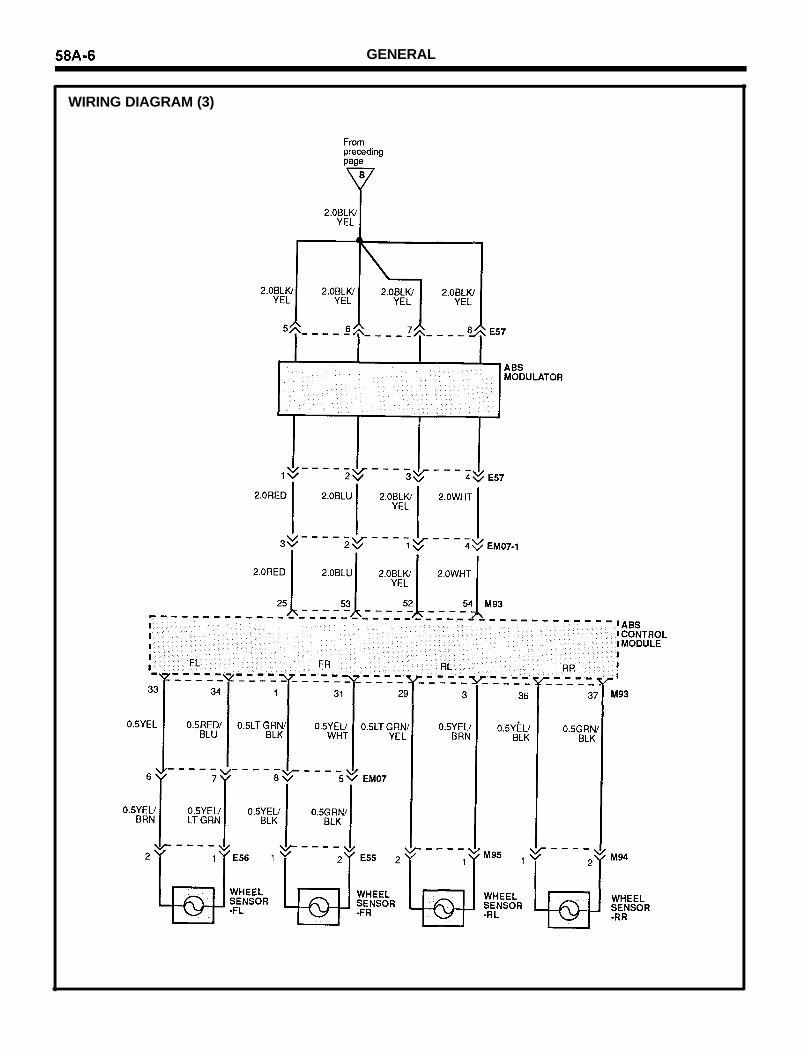
WIRING DIAGRAM (3)
GENERAL
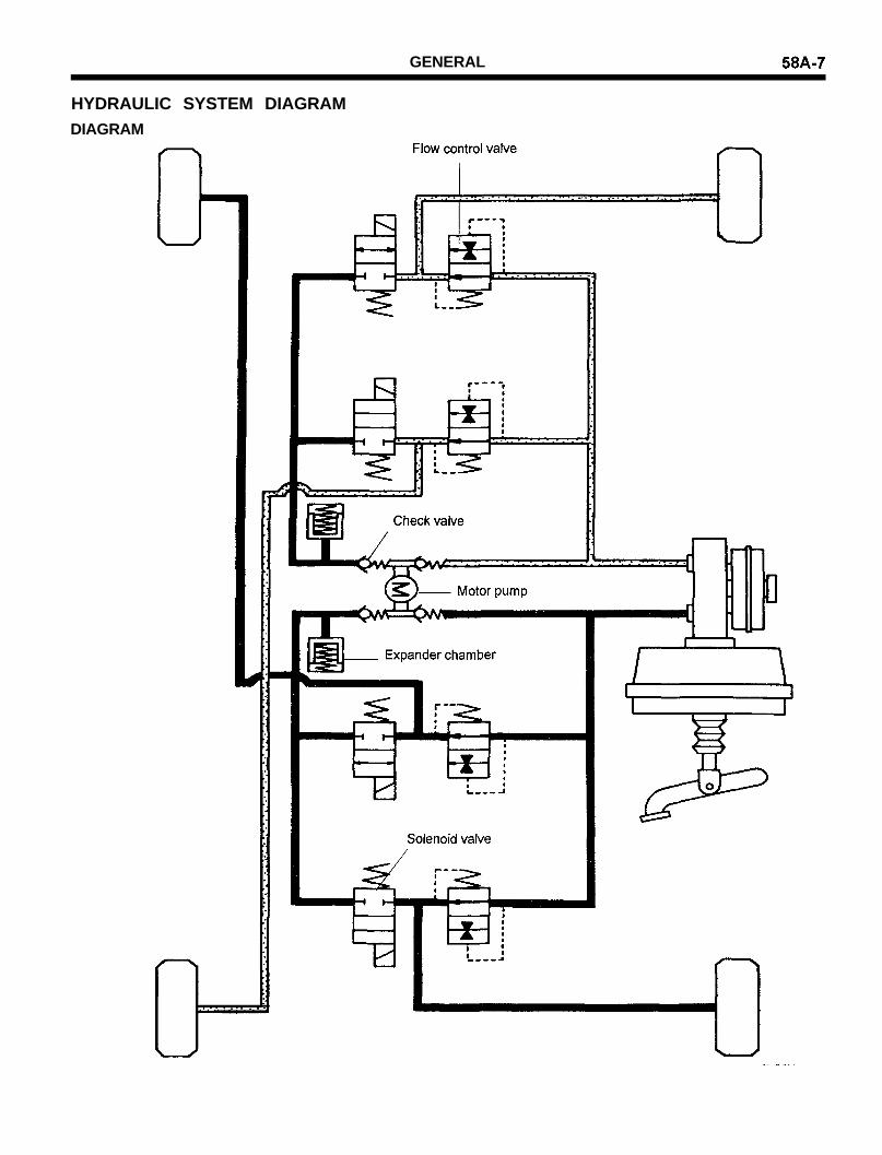
HYDRAULIC SYSTEM DIAGRAMDIAGRAM

58A-8 GENERAL
ABSCM CONNECTOR
I : INPUTO : OUTPUT F/SF : Fail safeSRI : Service Reminder Indicator DLC : Data Link Connector
Modulator connector (E57)
Relay Box connector (E58)
ABS MODULATOR AND ABS RELAY 58A-9
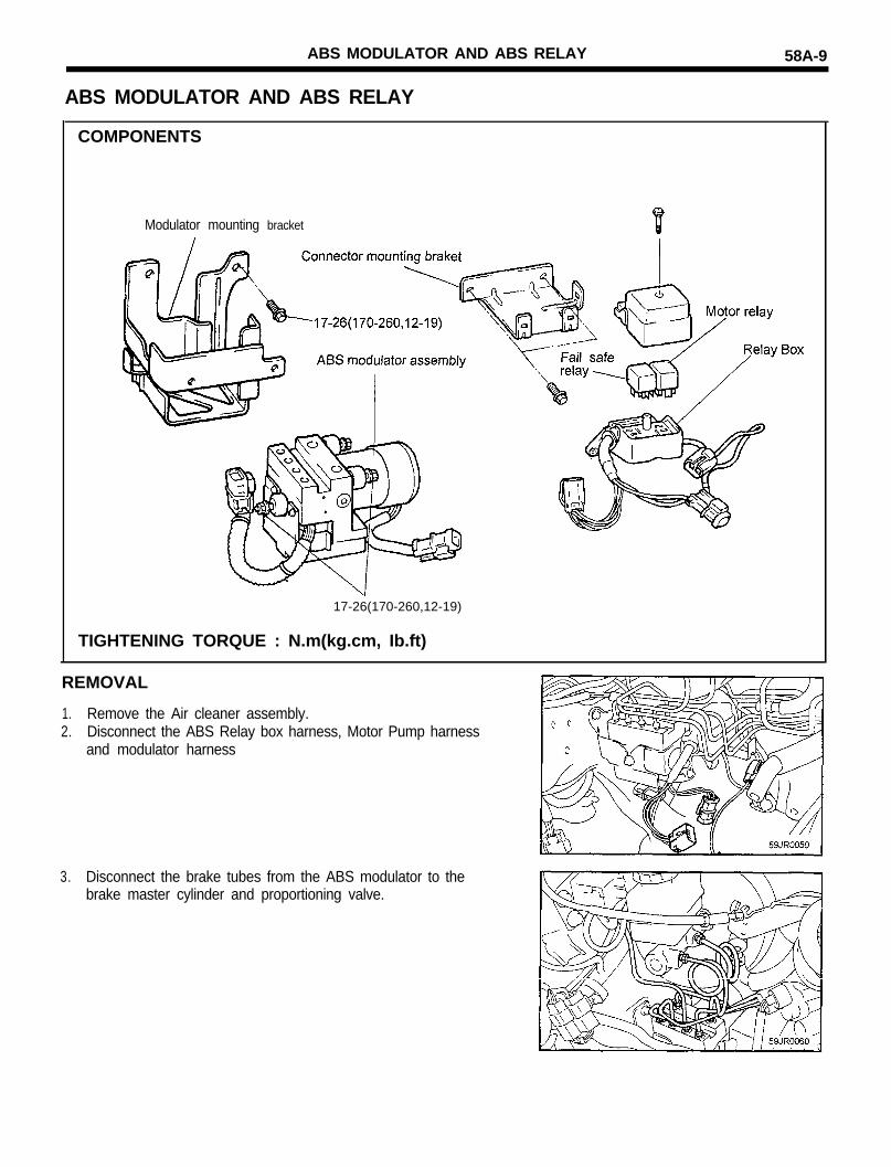
ABS MODULATOR AND ABS RELAY
COMPONENTS
Modulator mounting bracket
17-26(170-260,12-19)
TIGHTENING TORQUE : N.m(kg.cm, Ib.ft)
REMOVAL
1. Remove the Air cleaner assembly.2. Disconnect the ABS Relay box harness, Motor Pump harness
and modulator harness
3. Disconnect the brake tubes from the ABS modulator to thebrake master cylinder and proportioning valve.
58A-10 ABS MODULATOR AND ABS RELAY
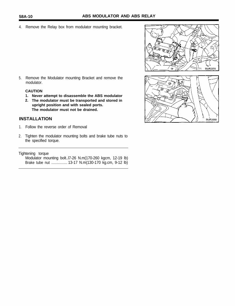
4. Remove the Relay box from modulator mounting bracket.
5. Remove the Modulator mounting Bracket and remove themodulator.
CAUTION1. Never attempt to disassemble the ABS modulator2. The modulator must be transported and stored in
upright position and with sealed ports.The modulator must not be drained.
INSTALLATION
1. Follow the reverse order of Removal
2. Tighten the modulator mounting bolts and brake tube nuts tothe specified torque.
Tightening torqueModulator mounting bolt..l7-26 N.m(170-260 kgcm, 12-19 lb)Brake tube nut ................ 13-17 N.m(130-170 kg.cm, 9-12 lb)

ABSCM (ABS control module) 58A-11
ABSCM (ABS Control Module)
2. Remove the ABSCM.
REMOVAL
1. Remove the luggage side trim
58A-12 WHEEL SPEED SENSOR
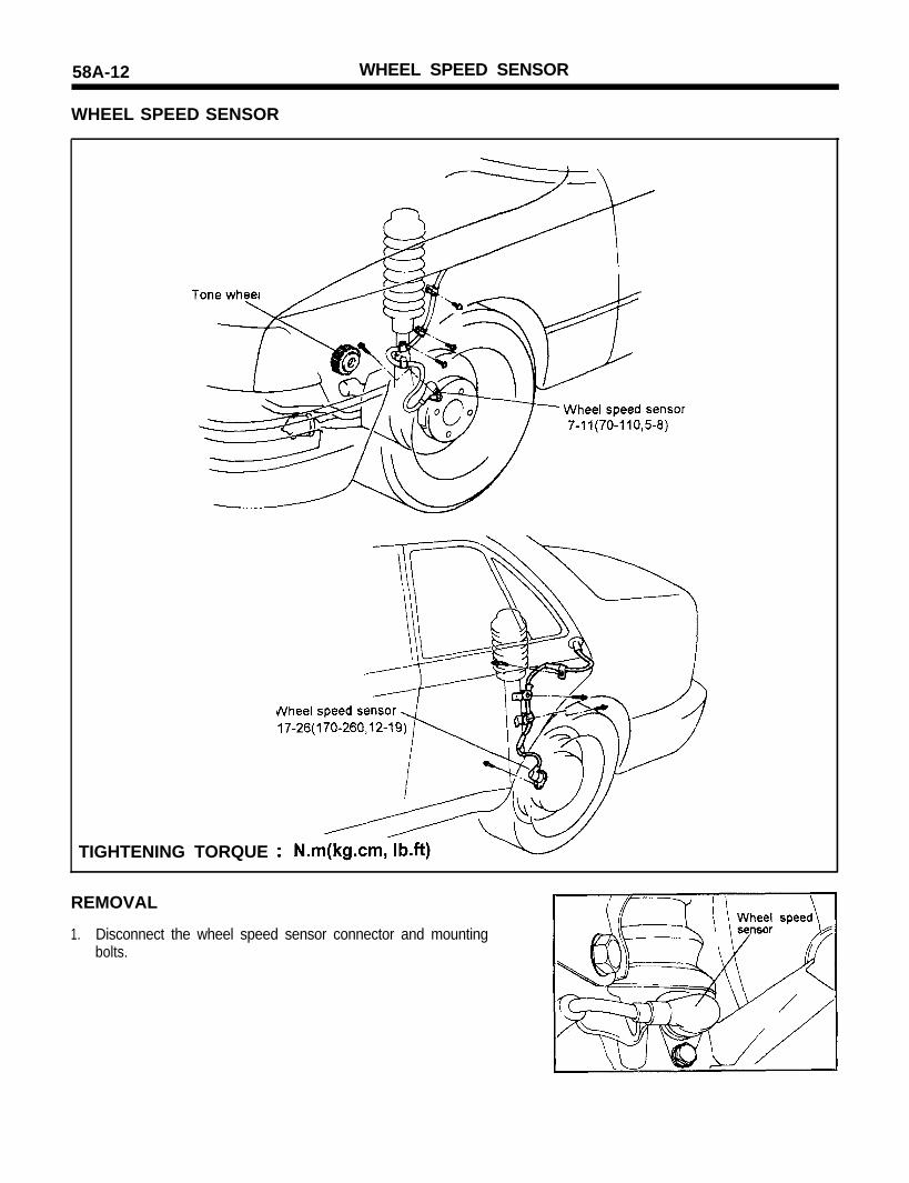
WHEEL SPEED SENSOR
TIGHTENING TORQUE
REMOVAL
1. Disconnect the wheel speed sensor connector and mountingbolts.

WHEEL SPEED SENSOR 58A-13
INSPECTION
1. Connect an ohmmeter between the wheel speed sensor termi-nals and measure the resistance.
Service standard : Front : 1275-1495Rear : 1260-1540
2. Connect a voltmeter between the wheel speed sensor termi-nals, and measure the voltage by turning the wheel.
NOTESet the voltmeter to measure AC voltage.
Service standard : AC voltage detected.

58A-14 BLEEDING OF BRAKE SYSTEM
BLEEDING OF BRAKE SYSTEM
NOTEThere are no special bleeding procedure for the ABS SYS-TEM. For bleeding please use the standard rules as describedfor the conventional brake system as follows.
BLEEDING OF BRAKE SYSTEM
1. Remove the reservoir cap and fill the brake reservoir withbrake fluid.
CAUTIONDo not allow brake fluid remain on a painted surface.Wash it off immediately.
NOTEWhen bleeding by pressurized fluid, do not depress thebrake pedal.
2.
3.4.
Connect the vinyl tube to the wheel cylinder bleeder screw, andinsert the other end of tube in a half full container of brake fluid.Slowly pump the brake pedal several times.While depressing the brake pedal fully, loosen the bleederscrewuntil fluid starts to run out. Then close the bleeder screw.
5. Repeat the 3 and 4 until there are no more bubbles in the fluid.6. Tighten the bleeder plug screw.
7.
Bleeder screw tightening torque ...........................................Front : 7-13 Nm (70-130 kg.cm, 5-10 Ib.ft)Rear : 8-20 Nm (80-200 kg.cm, 6-15 Ib.ft)
Repeat the above procedure for each wheel in the sequenceshown in the illustration.

TROUBLESHOOTING 58A-15
SYSTEM DIAGNOSIS STEPINDICATOR CHECK
When the ignition switch is turned on, check that the ABS SRI goesON for 6 seconds.If the SRI is not illuminated immediately after ignition on, the ABSfail safe relay may be at fault.
SCAN TOOL CHECK
1. Turn the ignition OFF.2. Connect the scan tool to the data link connector in the fuse box.3. Connect the power-source terminal of the scan tool to the
cigarette lighter socket.4. Turn the ignition ON.5. Use the scan tool to check the self-diagnosis codes.6. After completion of the repair or correction of the problems, turn
OFF the ignition switch; then erase the stored diagnostictrouble codes using the scan tool.
7. Disconnect the scan tool.
CONNECTOR CHECK
1. Remove the battery negative (-) terminal.2. Disconnect the connectors and check the terminals following
the troubleshooting procedure.
NOTEWhen performing the test procedures, be careful not todamage the connector terminals.
ABS Servicereminder indicator
Anti-lock Brake system
GROUND
DATA LINK CONNECTOR

TROUBLESHOOTING
Diagnostic trouble code chart
Diagnostictrouble
code No.Scan Tool display Diagnosis item Description
19 TONE WHEEL
21 SOL. LF-SHRT
CHECK THE TONEWHEELSLEFT FRONT SOLENOID
Check for a defective tone wheel on awheel.
Detection for short circuit to +I2 Volt forthe left front solenoid.
22 SOL. LF-OPEN LEFT FRONT SOLENOID Detection for open circuit or short circuit toGND for the left front solenoid.
23 SOL. RF-SHRT RIGHT RIGHT SOLENOID Detection for short circuit to +12 Volt forthe right front solenoid.
24 SOL. RF-OPEN RIGHT FRONT SOLENOID Detection for open circuit or short circuit toGND for the right front solenoid.
25 SOL. LR-SHRT LEFT REAR SOLENOID Detection for short circuit to +I2 Voltfor the left rear solenoid.
26 SOL. LR-OPEN LEFT REAR SOLENOID Detection for open circuit or short circuit toGND for the left rear solenoid.
27 SOL. RR-SHRT RIGHT REAR SOLENOID Detection for short circuit to +I2 Voltfor the right rear solenoid.
28 SOL. RR-OPEN RIGHT REAR SOLENOID Detection for open circuit or short circuit toGND for the right rear solenoid.
31 SNSR. LF-GAP LEFT FRONT SENSOR Detection for the air gap of the tone wheel.This detection will be activated if all wheelspeeds are zero and the ABS-function is notactive.
32 SNSR. RF-GAP RIGHT FRONT SENSOR Detection for the air gap of the tone wheel.This detection will be activated if all wheelspeeds are zero and the ABS-function is notactive.
33 SNSR. LR-GAP LEFT REAR SENSOR Detection for the air gap of the tone wheel.This detection will be activated if all wheelspeeds are zero and the ABS-function is notactive.
34 SNSR. RR-GAP RIGHT REAR SENSOR Detection for the air gap of the tone wheel.This detection will be activated if all wheelspeeds are zero and the ABS-function is notactive.
35 MOTOR PUMP MOTOR PUMP Faulty or seized up motor pump.

TROUBLESHOOTING 58A-17
Diagnostictrouble
code No.Scan Tool display Diagnosis item Description
36 MP RLY-OPEN MOTOR RELAY CIRCUIT Detection for a open circuit or a shortcircuit to GND from the motor pump relay.
37 MP RLY-SHRT MOTOR RELAY CIRCUIT Detection for a short circuit to +12 Voltfrom the motor pump relay.
38 MP BATT-SHRT
39 MP GND-SHRT
41 FAIL RLY-SHRT
FAIL RLY-OPEN
PUMP MOTOR
PUMP MOTOR
FAIL SAFE RELAY
FAIL SAFE RELAY
Detection for a short circuit at the motorpumpDetection for a short circuit to GND at themotor pump
Fail safe relay contacts are short circuit.
42 Fail safe relay contacts are open circuit
43 FAIL COIL FAIL SAFE RELAY COIL The current from the fail safe relay is toohigh or too low
44 ABS SRI-GND Detection of a short circuit of the ServiceReminder Indicator (Permanently on)
45 ABS SRI-DIODE Detection for a open circuit of the diode forthe Service Reminder Indicator ABS.
54 ABS SRI-BATT Detection for a short circuit to +12V ofthe Service Reminder Indicator.
55 ABS SRI-OPEN Detection for a open circuit of the ServiceReminder Indicator ABS.
56 BATT. VOLT-LO
SERVICE REMINDERINDICATOR
SERVICE REMINDERINDICATOR DIODE
SERVICE REMINDERINDICATOR
SERVICE REMINDERINDICATOR
BATTERY VOLTAGE Battery voltage out of the function range(Under voltage) for the system.
57 BATT. VOLT-HI Battery voltage out of the function range(Over voltage) for the system.
62 SNSR. LF-OPEN Sensor open circuit or short to 12 Voltdetection for the left front wheel
63 SNSR. RF-OPEN
BATTERY VOLTAGE
LEFT FRONT SENSORCIRCUIT
RIGHT FRONT SENSORCIRCUIT
LEFT REAR SENSORCIRCUIT
Sensor open circuit or short to 12 Voltdetection for the right front wheel.
64 SNSR. LR-OPEN Sensor open circuit or short to 12 Voltdetection for the left rear wheel.
65 SNSR. RR-OPEN
SNSR. LF-SHRT
RIGHT REAR SENSORCIRCUIT
LEFT FRONT SENSORCIRCUIT
Sensor open circuit or short to 12 Voltdetection for the right rear wheel.
66 Sensor short to GND detection for the leftfront wheel

58A-18 TROUBLESHOOTING
Diagnostictrouble
code No.Scan Tool display Diagnosis item Description
Sensor short to GND detection for theright front wheel.
Sensor short to GND detection for theleft rear wheel.
Sensor short to GND detection forthe right rear wheel.
Detection for missing teeth on the tonewheel or speed jumps over-100g on theleft front wheel.
Detection for missing teeth on the tonewheel or speed jumps over-100g on theright front wheel.
Detection for missing teeth on the tonewheel or speed jumps over-100g on theleft rear wheel.
Detection for missing teeth on the tonewheel or speed jumps over-100g on theright rear wheel.
Detection of a ABSCM (ABS Controlmodule) error.
67 SNSR. RF-SHRT RIGHT FRONT SENSORCIRCUIT
LEFT REAR SENSORCIRCUIT
RIGHT REAR SENSORCIRCUIT
68 SNSR. LR-SHRT
SNSR. RR-SHRT
SNSR. LF-S. JMP
SNSR. RF-S.JMP
SNSR. LR-S.JMP
SNSR. RR-S.JMP
69
LEFT FRONT TONE WHEEL71
RIGHT FRONT TONEWHEEL
72
LEFT REAR TONE WHEEL73
74 RIGHT REAR TONEWHEEL
77 ABSCM-FAIL ABSCM ERROR
ACTUATOR TEST- Test condition : Ignition “ON”-
SCAN TOOL (MUT) DISPLAY RECOGNITION REMARKS
Front left solenoid valve operation(Click sounds)
Actuation time is limited toMAX. 20 seconds
21. SOLENOID - LF
23. SOLENOID - RF
25. SOLENOID - LR
Front right solenoid valve operation(Click sounds)
Rear left solenoid valve operation(Click sounds)
Rear right solenoid valve operation(Click sounds)
Motor pump relay operation(Click sounds)
27. SOLENOID - RR
36. MP. RLY
99. ACT. TST. STOP Stop actuator test
58A-19
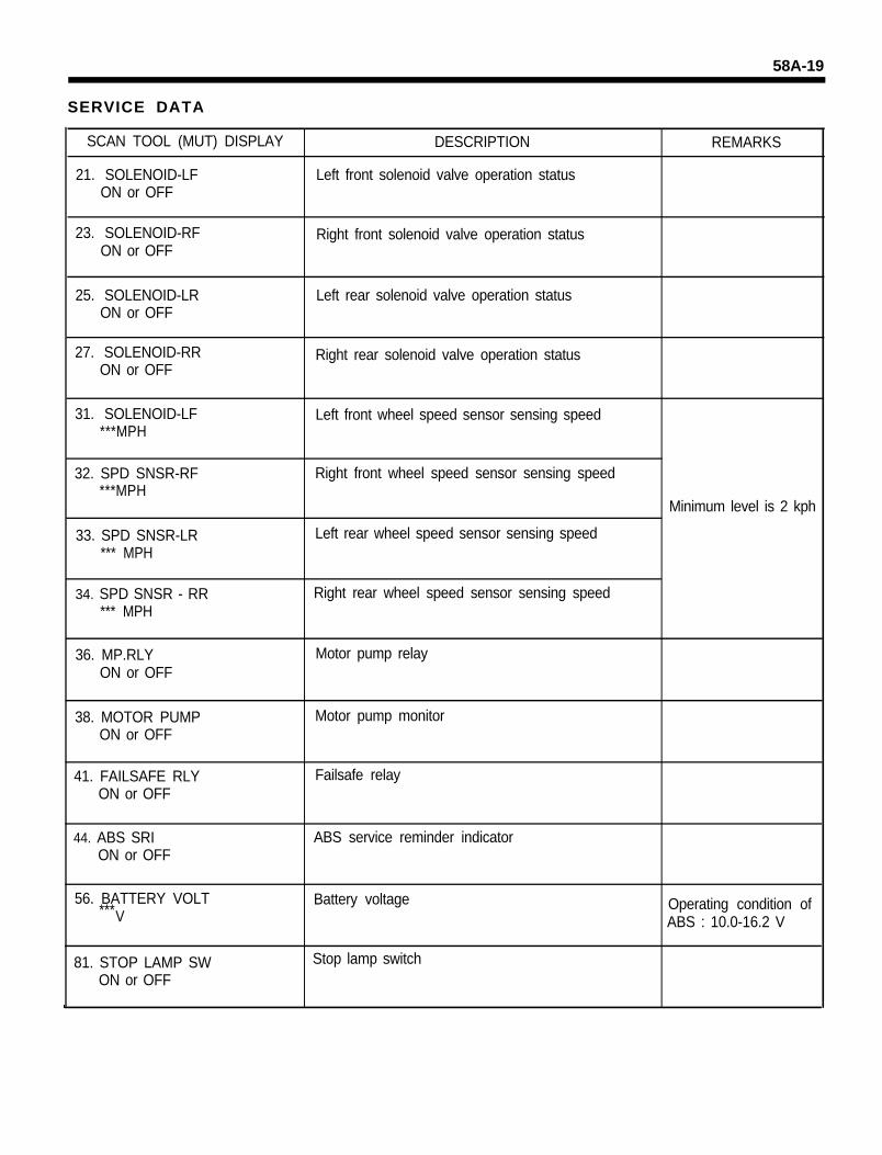
SERVICE DATA
SCAN TOOL (MUT) DISPLAY
21. SOLENOID-LFON or OFF
DESCRIPTION
Left front solenoid valve operation status
REMARKS
23. SOLENOID-RFON or OFF
Right front solenoid valve operation status
25. SOLENOID-LRON or OFF
Left rear solenoid valve operation status
27. SOLENOID-RRON or OFF
Right rear solenoid valve operation status
31. SOLENOID-LF***MPH
Left front wheel speed sensor sensing speed
32. SPD SNSR-RF***MPH
33. SPD SNSR-LR*** MPH
Right front wheel speed sensor sensing speed
Left rear wheel speed sensor sensing speed
Minimum level is 2 kph
34. SPD SNSR - RR*** MPH
Right rear wheel speed sensor sensing speed
36. MP.RLYON or OFF
Motor pump relay
38. MOTOR PUMPON or OFF
Motor pump monitor
41. FAILSAFE RLYON or OFF
Failsafe relay
44. ABS SRION or OFF
ABS service reminder indicator
56. BATTERY VOLT***V
Battery voltage Operating condition ofABS : 10.0-16.2 V
81. STOP LAMP SWON or OFF
Stop lamp switch
58A-20 TROUBLESHOOTING
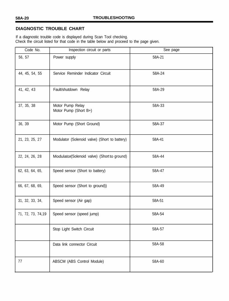
DIAGNOSTIC TROUBLE CHART
If a diagnostic trouble code is displayed during Scan Tool checking.Check the circuit listed for that code in the table below and proceed to the page given.
Code No. Inspection circuit or parts See page
56, 57 Power supply 58A-21
44, 45, 54, 55 Service Reminder Indicator Circuit 58A-24
41, 42, 43 Fault/shutdown Relay 58A-29
37, 35, 38 Motor Pump Relay 58A-33Motor Pump (Short B+)
36, 39 Motor Pump (Short Ground) 58A-37
21, 23, 25, 27 Modulator (Solenoid valve) (Short to battery) 58A-41
22, 24, 26, 28 Modulator to(Solenoid valve) (Short ground) 58A-44
62, 63, 64, 65, Speed sensor (Short to battery) 58A-47
66, 67, 68, 69, Speed sensor (Short to ground)) 58A-49
31, 32, 33, 34, Speed sensor (Air gap) 58A-51
71, 72, 73, 74,19 Speed sensor (speed jump) 58A-54
Stop Light Switch Circuit 58A-57
Data link connector Circuit 58A-58
77 ABSCM (ABS Control Module) 58A-60

TROUBLESHOOTING 58A-21
CIRCUIT INSPECTION
POWER SOURCE VOLTAGE
Detection of battery voltage out of the function range for thesystem.
Error Code Scan tool display
56 BATT. VOLT-LO
57 BATT. VOLT-HI
Symptom Possible Cause
ABSCM power supply voltage is o Battery8.9V or below o Charging circuit
o Harness connector between batteryABSCM power supply voltage and ABSCM, ABSCM and bodyis 16.2V or higher ground.
WIRING DIAGRAM

58A-22 TROUBLESHOOTING
INSPECTION PROCEDURE
1. Check the ABSCM fuse
1. Remove the FUSE 13 and Inspect in theDASH FUSE BOX.
Continuity
Replace Fuse 13 then recheck withScan Tool procedure.
2. Check Voltage between Battery (+) and GND of ABSCM connector
M93 ABSCM harnessside connector
Connect the ABSCM and re-check the diagnosticcode, if code 56, 57 displayed, check and refit theABSCM.
1. Remove battery negative(-) terminal.2. Remove the ABSCM and disconnect the
connector3. Connect battery negative(-) terminal4. Turn ignition switch to ON position5. Measure the supply voltage between terminals
50 and 27.
9.5V ~ 14.2V
TROUBLESHOOTING 58A-23
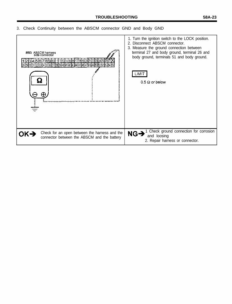
3. Check Continuity between the ABSCM connector GND and Body GND
Check for an open between the harness and theconnector between the ABSCM and the battery
1. Turn the ignition switch to the LOCK position.2. Disconnect ABSCM connector.3. Measure the ground connection between
terminal 27 and body ground, terminal 26 andbody ground, terminals 51 and body ground.
1 Check ground connection for corrosionand loosing
2. Repair harness or connector.

58A-24 TROUBLESHOOTING
ABS SRI (Service Reminder Indicator) Circuit.
If the trouble occurs, ABSCM lights the ABS-SRI while at the sametime terminating ABS operation. At this time, the ABSCM recordsa diagnostic code in memory.If the ABSCM detects a fault in the Anti-Lock Brake System, theABSCM turns the ABS SRI on and dissables the ABS. At the sametime a trouble code is stored in the ABSCM memory.
Code No. Scan tool display Symptom Possible Cause
44
45
54
55
ABS SRI-GND
ABS SRI-DIODE
ABS SRI-BATT
ABS SRI-OPEN
Service Reminder Indicator short to groundService Reminder Indicator
Service Reminder Indicator diode not OKBox (Fail safe Relay)
Service Reminder Indicator short to 12V
Service Reminder Indicator open circuitFuse
WIRING DIAGRAM
0.5BLK/W H T
TROUBLESHOOTING 58A-25
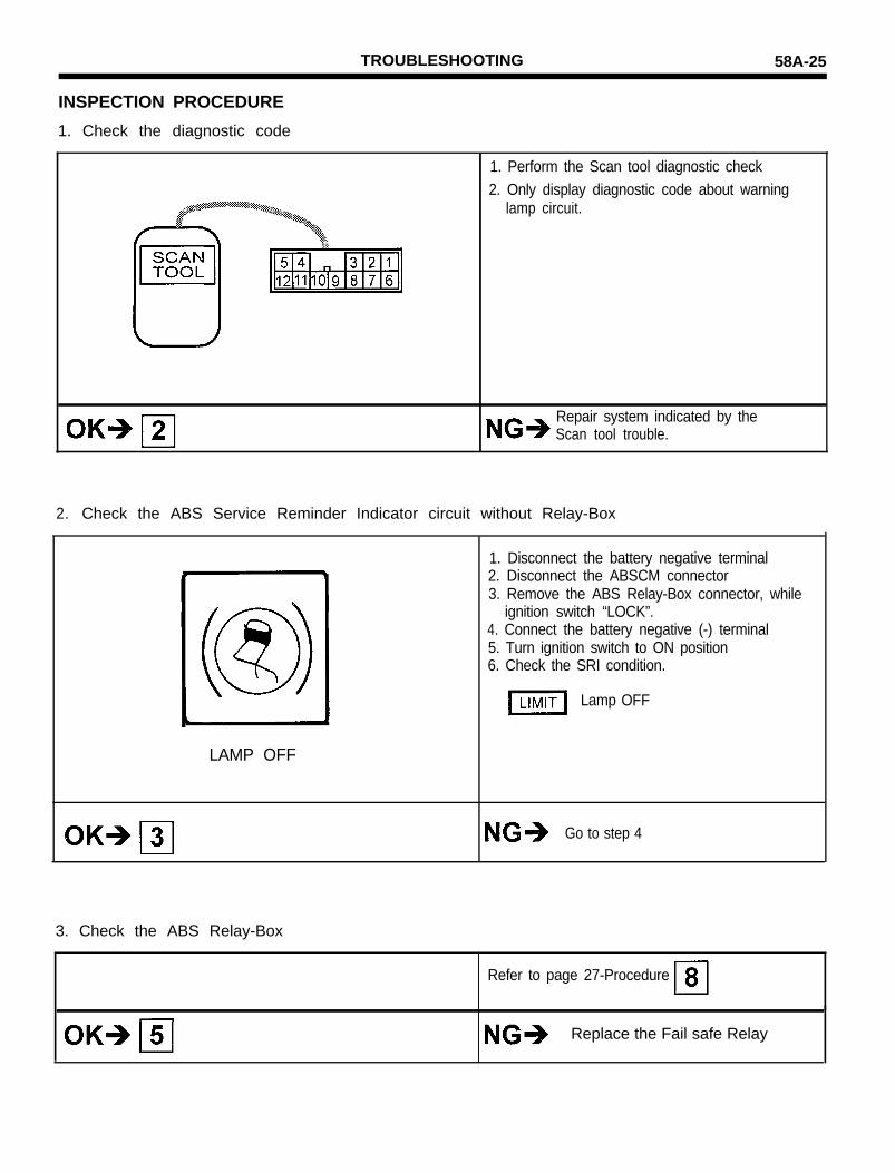
INSPECTION PROCEDURE
1. Check the diagnostic code
1. Perform the Scan tool diagnostic check2. Only display diagnostic code about warning
lamp circuit.
Repair system indicated by theScan tool trouble.
2. Check the ABS Service Reminder Indicator circuit without Relay-Box
LAMP OFF
1. Disconnect the battery negative terminal2. Disconnect the ABSCM connector3. Remove the ABS Relay-Box connector, while
ignition switch “LOCK”.4. Connect the battery negative (-) terminal5. Turn ignition switch to ON position6. Check the SRI condition.
Lamp OFF
Go to step 4
3. Check the ABS Relay-Box
Refer to page 27-Procedure
Replace the Fail safe Relay

56A-26 TROUBLESHOOTING
4. Check the ABS Relay-Box harness
E58 Relay Box harnessside connector
5. Check the ABSCM connector harness
M93 ABSCM harnessside connector
Refit the ABSCM and recheck
1. Turn ignition switch to “LOCK” position.2. Disconnect the Relay Box connector.3. Check the continuity between the Relay-Box
harness terminal 3 and body ground.
No continuity
Repair the harness
1. Disconnect the battery negative terminal.2. Disconnect the ABSCM connector.3. Check the continuity between ABSCM.
connector harness pin No. 17 and body ground.
No continuity
Repair the harness

TROUBLESHOOTING 58A-27
6. Check the fuse
Inspect the fuse No.10 located in the Dash Fuse Box
7. Check the ABS SRI Circuit

58A-28 TROUBLESHOOTING
9. Check the Fail safe relay
1. Turn ignition switch to “LOCK” position.2. Remove the Relay-box cover.3. Remove the Fail-safe relay.4. Check continuity between terminals as follows.
5. Apply battery voltage between terminals 2
CautionNever attempt to continue 2 sec. or more
6. Check continuity between terminals as follows.
Terminals 1 and 5
Terminals 3 and 5
Continuity
No continuity
Re-connect the ABS-Relay Replace the Fail safe relay

TROUBLESHOOTING 58A-29
ABS RELAY BOX CIRCUIT(FAIL SAFE RELAY)
Fail safe relay supplies battery voltage to the modulator, After theignition switch is turned ON position, the relay goes on, if the initialcheck is good.If a problem occurs in the ABS system, the ABSCM disables therelay and the ABS is disabled.
Code No. MUT display Symptom Possible Cause
FAIL RLY-SHRT Fail safe relay not set activecontact signal stay close
FAIL RLY-OPEN Fail safe relay set active contactsignal stay not closed
FAIL COIL
o Fail safe relayo Harness between Relay box and
ABSCMo ABSCM
o Fail safe Relayo Harness between Relay box and Power
sourceo Harness between Relay box and
ABSCMo ABSCM
WIRING DIAGRAM

58A-30 TROUBLESHOOTING
INSPECTION PROCEDURE
1. Check ABS power supply.
2. Check the ABS Relay Box (Fail safe Relay)
1. Turn ignition switch to “LOCK” position.2. Disconnect the ABS Relay Box connector3. Measure the voltage between terminal E58-7
and E59-1 at harness side connector
Between 9.5--14.2V
Repair the harness and connector fromBattery Voltage, Relay box and bodyground
1. Turn ignition switch to “LOCK” position.2. Disconnect the ABS Relay Box connector.3. Check for continuity between as follows.
4. Apply battery voltage between terminal 2 and 7.
CautionNever attempt to continue 2 sec. or more
5. Check for continuity as follows.
TROUBLESHOOTING 58A-31
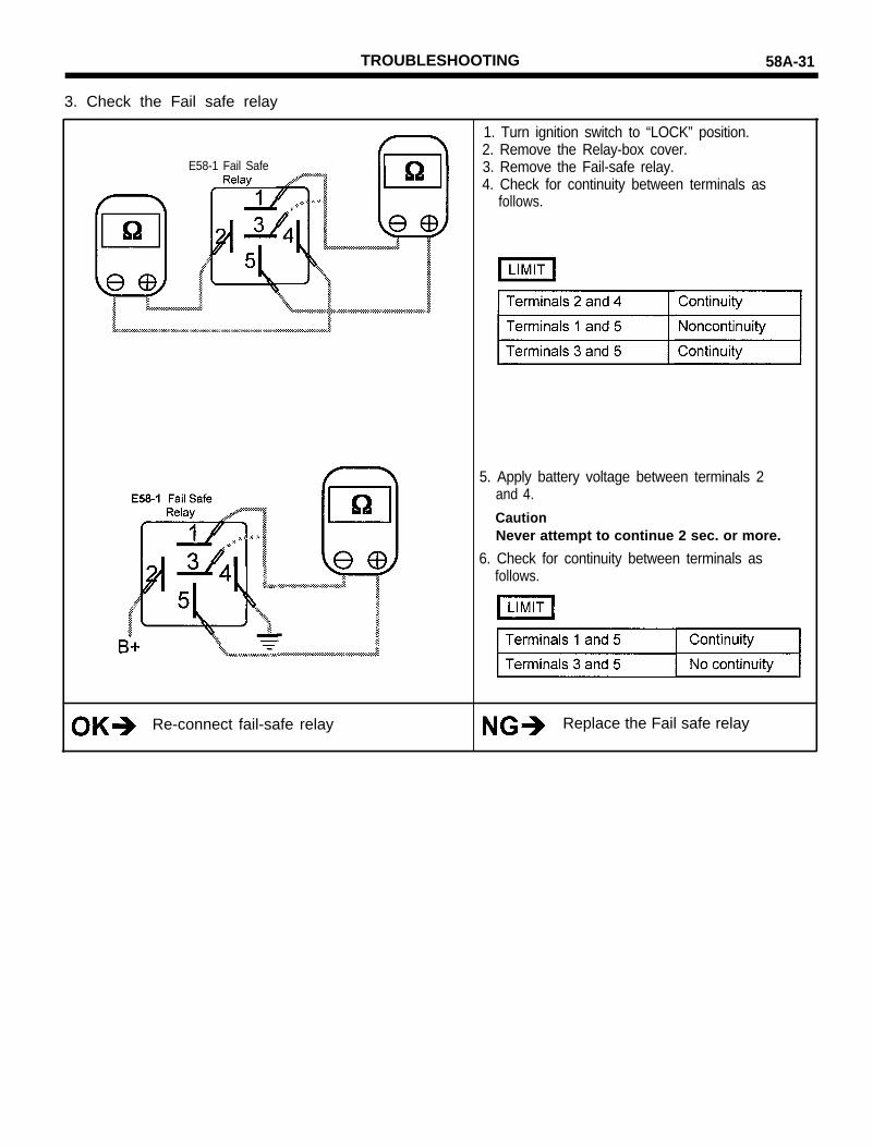
3. Check the Fail safe relay
E58-1 Fail Safe
Re-connect fail-safe relay
1. Turn ignition switch to “LOCK” position.2. Remove the Relay-box cover.3. Remove the Fail-safe relay.4. Check for continuity between terminals as
follows.
5. Apply battery voltage between terminals 2and 4.
CautionNever attempt to continue 2 sec. or more.
6. Check for continuity between terminals asfollows.
Replace the Fail safe relay
58A-32 TROUBLESHOOTING
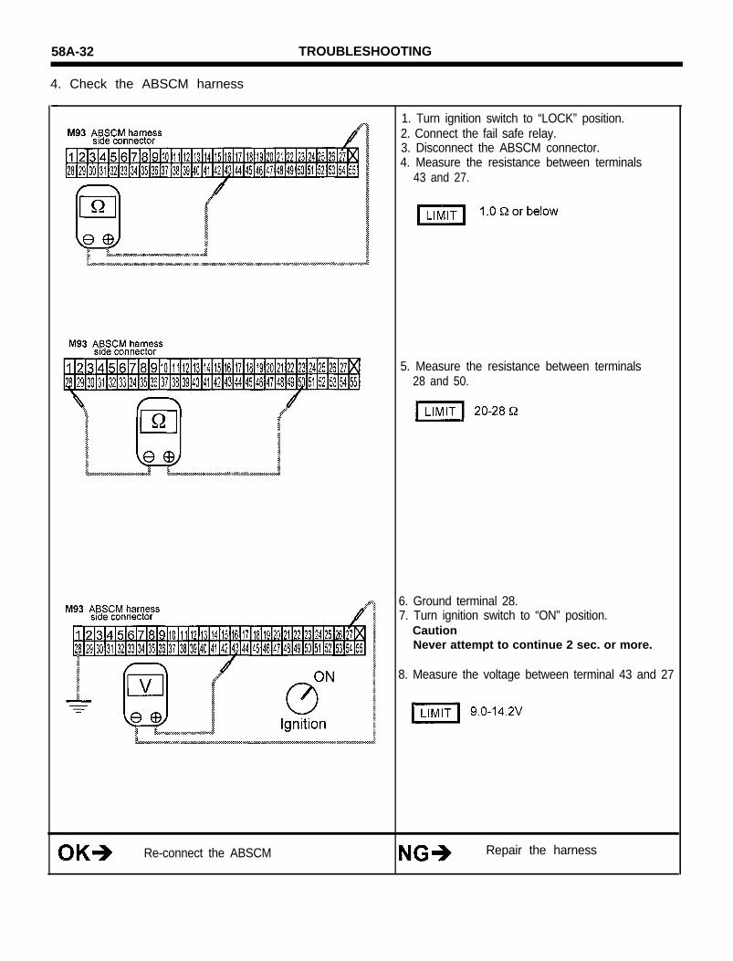
4. Check the ABSCM harness
1. Turn ignition switch to “LOCK” position.2. Connect the fail safe relay.3. Disconnect the ABSCM connector.4. Measure the resistance between terminals
43 and 27.
5. Measure the resistance between terminals28 and 50.
6. Ground terminal 28.7. Turn ignition switch to “ON” position.
CautionNever attempt to continue 2 sec. or more.
8. Measure the voltage between terminal 43 and 27
Re-connect the ABSCM Repair the harness
TROUBLESHOOTING 58A-33
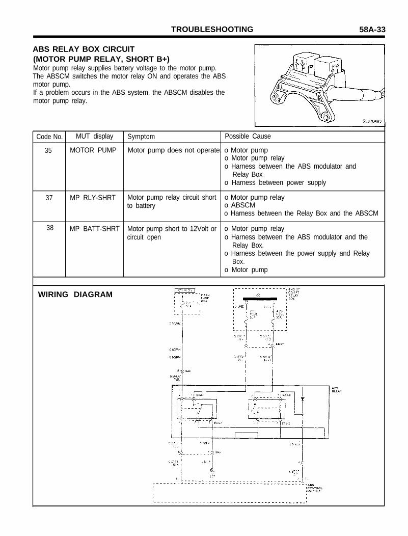
ABS RELAY BOX CIRCUIT(MOTOR PUMP RELAY, SHORT B+)Motor pump relay supplies battery voltage to the motor pump.The ABSCM switches the motor relay ON and operates the ABSmotor pump.If a problem occurs in the ABS system, the ABSCM disables themotor pump relay.
Code No. MUT display Symptom Possible Cause
35 MOTOR PUMP Motor pump does not operate. o Motor pumpo Motor pump relayo Harness between the ABS modulator and
Relay Boxo Harness between power supply
37 MP RLY-SHRT Motor pump relay circuit short o Motor pump relayto battery o ABSCM
o Harness between the Relay Box and the ABSCM
38 MP BATT-SHRT Motor pump short to 12Volt or o Motor pump relaycircuit open o Harness between the ABS modulator and the
Relay Box.o Harness between the power supply and Relay
Box.o Motor pump
WIRING DIAGRAM
58A-34 TROUBLESHOOTING
INSPECTION PROCEDURE
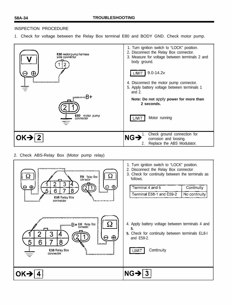
1. Check for voltage between the Relay Box terminal E80 and BODY GND. Check motor pump.
1. Turn ignition switch to “LOCK” position.2. Disconnect the Relay Box connector.3. Measure for voltage between terminals 2 and
body ground.
9.0-14.2v
4. Disconnect the motor pump connector.5. Apply battery voltage between terminals 1
and 2.
Note: Do not apply power for more than2 seconds.
Motor running
1. Check ground connection forcorrosion and loosing.
2. Replace the ABS Modulator.
2. Check ABS-Relay Box (Motor pump relay)
1. Turn ignition switch to “LOCK” position.2. Disconnect the Relay Box connector3. Check for continuity between the terminals as
follows.
4. Apply battery voltage between terminals 4 and5.
5. Check for continuity between terminals EL8-Iand E59-2.
TROUBLESHOOTING 58A-35
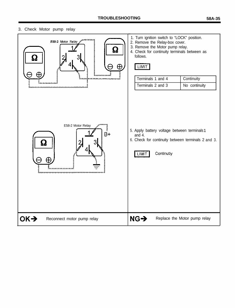
3. Check Motor pump relay
E58-2 Motor Relay
Reconnect motor pump relay
1. Turn ignition switch to “LOCK” position.2. Remove the Relay-box cover.3. Remove the Motor pump relay.4. Check for continuity terminals between as
follows.
Terminals 1 and 4
Terminals 2 and 3
Continuity
No continuity
5. Apply battery voltage between terminals1and 4.
6. Check for continuity between terminals 2 and 3.
Replace the Motor pump relay

56A-36 TROUBLESHOOTING
4. Check resistance between each terminal of ABSCM connector
Reconnect the ABSCM
1. Turn ignition switch to “LOCK” position.2. Disconnect the ABSCM connector.3. Check for resistance between terminals 19 and
43.
4. Turn ignition switch to “ON” position.5. Measure the voltage between terminals as
follows.
6. Turn ignition switch “LOCK” position.7. Ground terminal 19 and 28.8. Turn ignition switch “ON” position.
Motor running
NOTEDo not apply power for more than 2 seconds.
Repair the Harness

TROUBLESHOOTING 58A-37
ABS RELAY BOX CIRCUIT(MOTOR PUMP RELAY, SHORT GND)
Motor pump relay supplies battery voltage to the motor pump. TheABSCM switches the motor relay ON and operates the ABS motorpump.If a problem occurs in the ABS system, the ABSCM disables themotor pump relay.
Code No.
36
39
MUT display
MP RLY-OPEN
MP GND-SHRT
Symptom
Motor pump relay circuitopen or short to ground
Motor pump short toground
Possible Cause
o Motor pump relayo ABSCMo Harness between the Relay Box and the ABSCMo Harness between the power supply and the relay box
o Motor pump relayo Harness between the ABS modulator and Relay
Box.o Harness between the power supply and Relay Box.o Motor pump
WIRING DIAGRAM

50A-38 TROUBLESHOOTING
INSPECTION PROCEDURE
1. Check for voltage between the Relay Box terminal E59 and BODY GND.
2. Check the ABS Relay Box (Motor pump relay).
1. Turn ignition switch to “LOCK” position.2. Disconnect the Relay Box connector.3. Measure the voltage between terminals 2 and
body ground.
9.0-14.2V
Repair the Motor harness
1. Turn ignition switch to “LOCK” position.2. Disconnect the Relay Box connector.3. Check for continuity between the terminals as
follows.
4. Apply battery voltage between terminals 4and 5.
5. Check for continuity between terminals E58-1and E59-2.
Continuity
TROUBLESHOOTING 58A-39
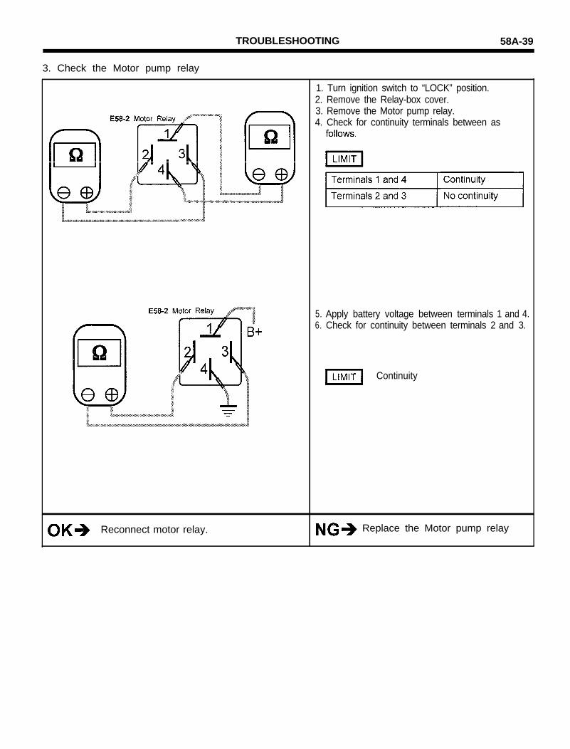
3. Check the Motor pump relay
Reconnect motor relay.
1. Turn ignition switch to “LOCK” position.2. Remove the Relay-box cover.3. Remove the Motor pump relay.4. Check for continuity terminals between as
5. Apply battery voltage between terminals 1 and 4.6. Check for continuity between terminals 2 and 3.
Continuity
Replace the Motor pump relay
TROUBLESHOOTING
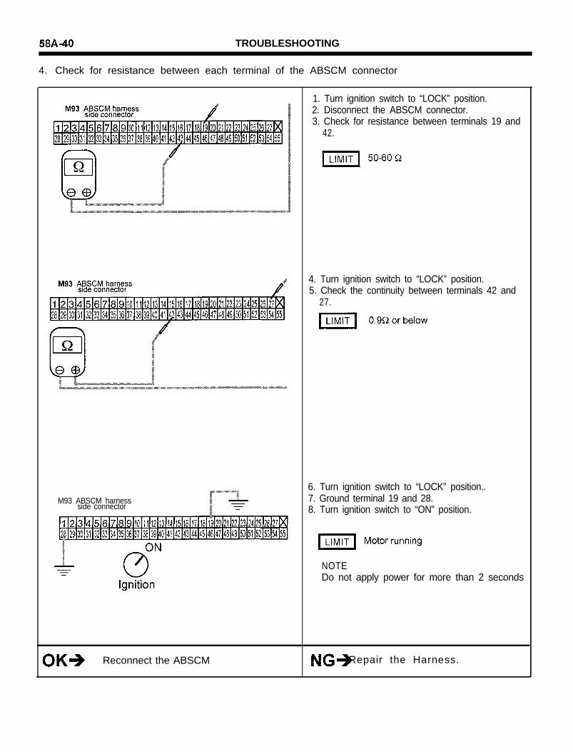
4. Check for resistance between each terminal of the ABSCM connector
M93 ABSCM harnessside connector
Reconnect the ABSCM Repair the Harness.
1. Turn ignition switch to “LOCK” position.2. Disconnect the ABSCM connector.3. Check for resistance between terminals 19 and
42.
4. Turn ignition switch to “LOCK” position.5. Check the continuity between terminals 42 and
27.
6. Turn ignition switch to “LOCK” position..7. Ground terminal 19 and 28.8. Turn ignition switch to “ON” position.
NOTEDo not apply power for more than 2 seconds

TROUBLESHOOTING 58A-41
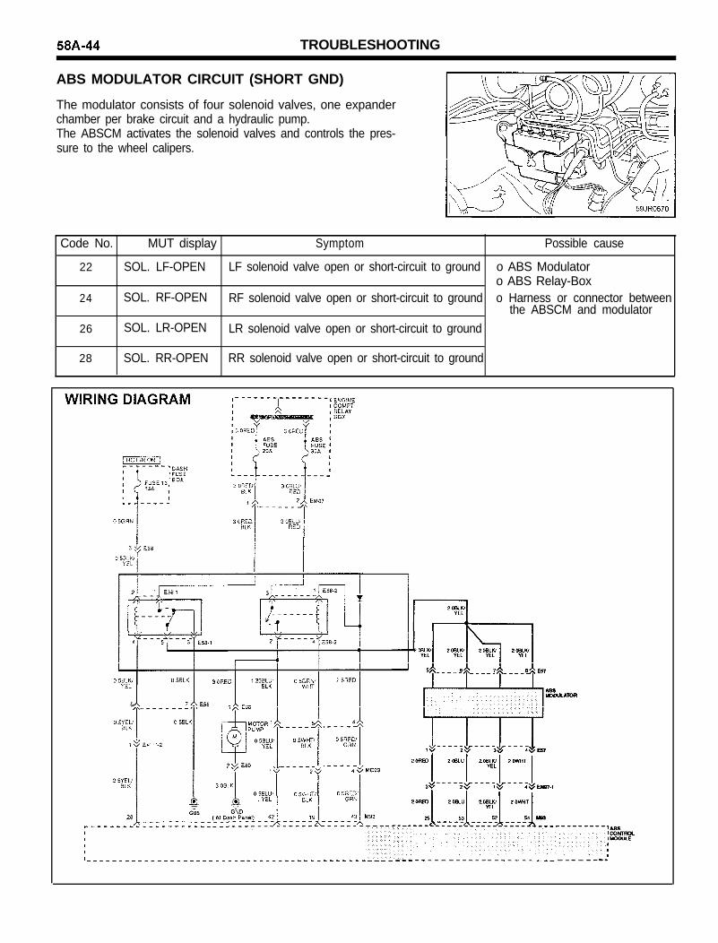
ABS MODULATOR CIRCUIT (SHORT B+)
The modulator consists of four solenoid valves, one expanderchamber per brake circuit and a hydraulic pump.The ABSCM activates the solenoid valves and controls the pres-sure to the wheel calipers.
Code No. MUT display Symptom Possible cause
21 SOL. LF-SHRT LF solenoid valve short-circuit to 12V o ABS Modulatoro ABS Relay-Box
23 SOL. RF-SHRT RF solenoid valve short-circuit to 12V o Harness or connector betweenABSCM and modulator
25 SOL. LR-SHRT LR solenoid valve short-circuit to 12V
27 SOL. RR-SHRT RR solenoid valve short-circuit to 12V
WIRING DIAGRAM

58A-42 TROUBLESHOOTING
INSPECTION PROCEDURE
1. Check for voltage between each terminal of the ABS modulator harness
2. Check the ABS-Modulator
1. Disconnect the battery negative (-) terminal.2. Disconnect the ABS modulator connector and
ABSCM connector.3. Connect the battery negative terminal and
ignition ON.4. Measure the voltage between terminals and
body ground as follows:
SOL. RR Terminal 5 and ground
SOL. LR Terminal 6 and ground
SOL. RF Terminal 7 and ground
SOL. LF Terminal 8 and ground
OV
OV
OV
OV
Check and repair harness betweenterminal 5, 6, 7, 8 and relay box ground.
1. Turn ignition switch to “LOCK” position.2. Disconnect the ABS modulator connector.3. Check the resistance between terminals as
follows.
Replace the ABS modulator.
SOL. : Solenoid
TROUBLESHOOTING 58A-43
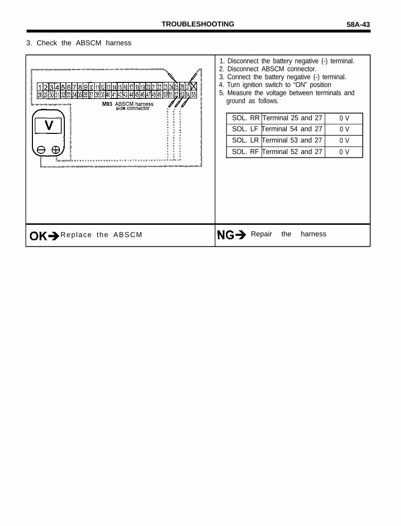
3. Check the ABSCM harness
1. Disconnect the battery negative (-) terminal.2. Disconnect ABSCM connector.3. Connect the battery negative (-) terminal.4. Turn ignition switch to “ON” position5. Measure the voltage between terminals and
ground as follows.
SOL. RR Terminal 25 and 27
SOL. LF Terminal 54 and 27
SOL. LR Terminal 53 and 27
SOL. RF Terminal 52 and 27
0 V
0 V
0 V
0 V
Replace the ABSCM Repair the harness
TROUBLESHOOTING
ABS MODULATOR CIRCUIT (SHORT GND)
The modulator consists of four solenoid valves, one expanderchamber per brake circuit and a hydraulic pump.The ABSCM activates the solenoid valves and controls the pres-sure to the wheel calipers.
Code No. MUT display Symptom Possible cause
22
24
26
SOL. LF-OPEN LF solenoid valve open or short-circuit to ground o ABS Modulatoro ABS Relay-Box
SOL. RF-OPEN RF solenoid valve open or short-circuit to ground o Harness or connector betweenthe ABSCM and modulator
SOL. LR-OPEN LR solenoid valve open or short-circuit to ground
28 SOL. RR-OPEN RR solenoid valve open or short-circuit to ground

TROUBLESHOOTING 58A-45
INSPECTION PROCEDURE
1. Check for continuity between each terminal of the ABS modulator harness
1. Disconnect the battery negative (-) terminal.2. Disconnect the ABS modulator connector and
ABSCM connector.3. Check for continuity between the terminals and
body ground as follows.
SOL. RR Terminal 5 and ground Continuity
SOL. RL Terminal 6 and ground Continuity
SOL. FR Terminal 7 and ground Continuity
SOL. FL Terminal 8 and ground Continuity
M93 ABSCM harnessside connector 4. Disconnect the ABSCM connector.
5. Ground ABSCM connector terminal 28.6. Connect the battery negative terminal7. Turn ignition switch to “ON” position.8. Measure voltage between terminals and body
SOL. : SOLENOID
Check and repair the harness betweenterminal 5, 6, 7, 8 and relay box ground.
58A-46 TROUBLESHOOTING
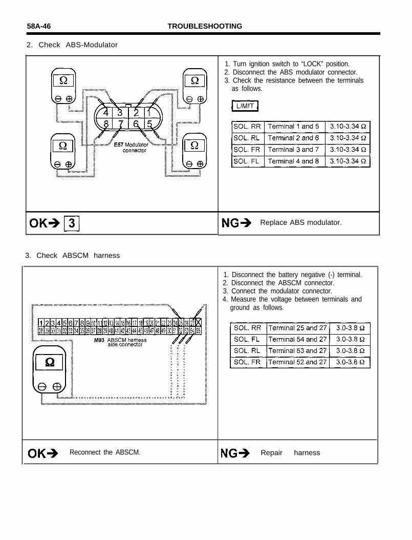
2. Check ABS-Modulator
3. Check ABSCM harness
1. Turn ignition switch to “LOCK” position.2. Disconnect the ABS modulator connector.3. Check the resistance between the terminals
as follows.
Replace ABS modulator.
1. Disconnect the battery negative (-) terminal.2. Disconnect the ABSCM connector.3. Connect the modulator connector.4. Measure the voltage between terminals and
ground as follows.
Reconnect the ABSCM. Repair harness
TROUBLESHOOTING 58A-47
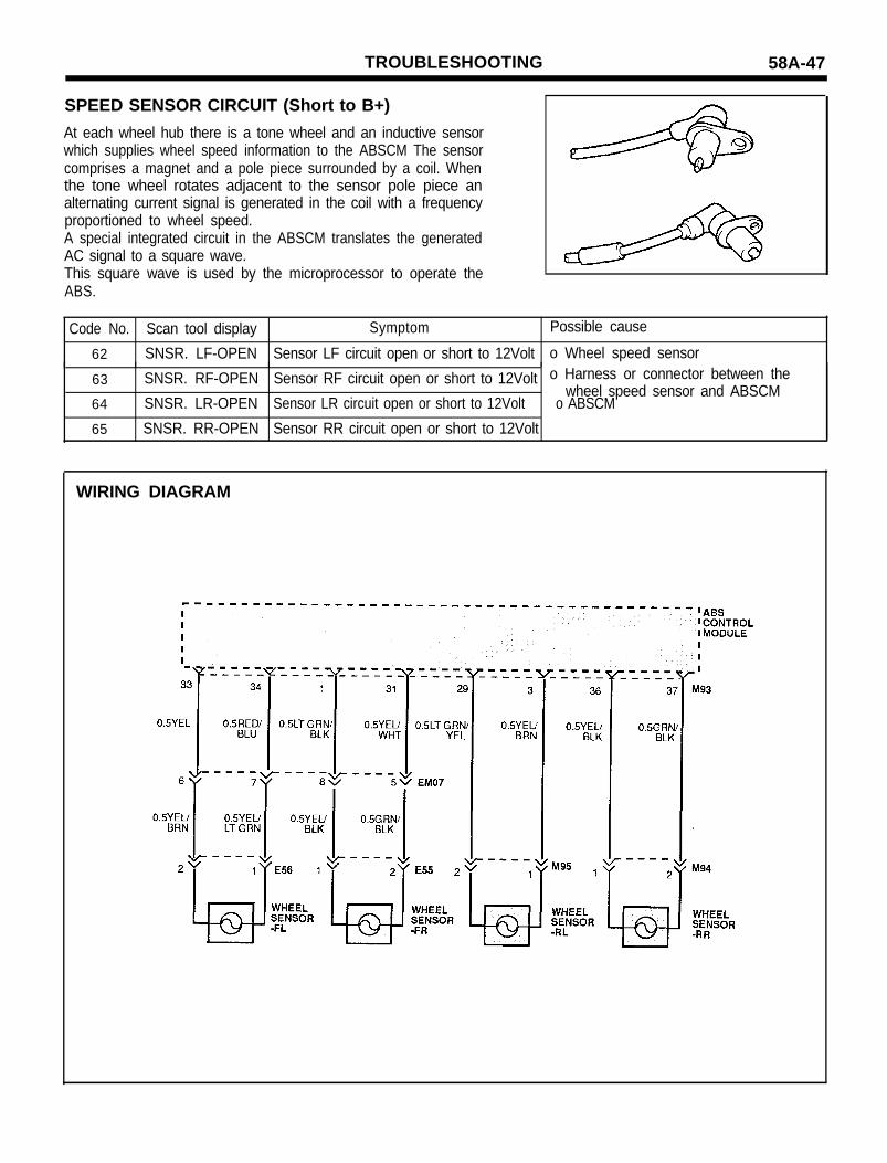
SPEED SENSOR CIRCUIT (Short to B+)
At each wheel hub there is a tone wheel and an inductive sensorwhich supplies wheel speed information to the ABSCM The sensorcomprises a magnet and a pole piece surrounded by a coil. Whenthe tone wheel rotates adjacent to the sensor pole piece analternating current signal is generated in the coil with a frequencyproportioned to wheel speed.A special integrated circuit in the ABSCM translates the generatedAC signal to a square wave.This square wave is used by the microprocessor to operate theABS.
Code No. Scan tool display Symptom Possible cause
62 SNSR. LF-OPEN Sensor LF circuit open or short to 12Volt o Wheel speed sensor
63
64
65
SNSR. RF-OPEN Sensor RF circuit open or short to 12Volt o Harness or connector between the
SNSR. LR-OPENwheel speed sensor and ABSCM
Sensor LR circuit open or short to 12Volt o ABSCM
SNSR. RR-OPEN Sensor RR circuit open or short to 12Volt
WIRING DIAGRAM

58A-48 TROUBLESHOOTING
INSPECTION PROCEDURE
1. Check Wheel Speed Sensor
1. Disconnect the wheel speed sensor.2. Measure the resistance between terminals 1
and 2 the of wheel speed sensor connector.
3. Measure voltage between wheel speed sensorconnector terminals 1, 2 and body ground.
Replace wheel speed sensor
2. Check the harness and to connector between the ABSCM and each wheel speed sensor
Re connect the ABSCM and re-check
1. Turn ignition switch to “LOCK” position2. Disconnect the ABSCM connector harness3. Turn ignition switch to “ON” position.4. Measure the resistance between the terminals
as follows.
5. Measure the voltage between sensor terminalsand body ground terminals as follows.
Repair the harness
SNSR.: SENSOR
TROUBLESHOOTING 58A-49
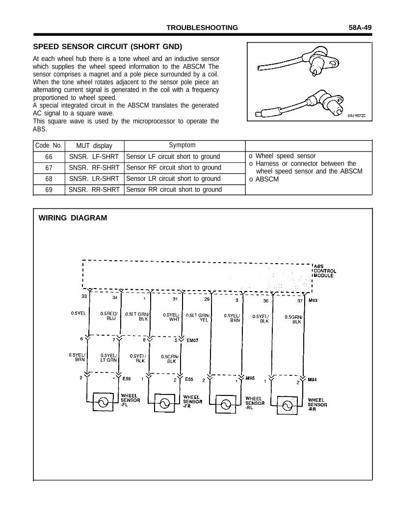
SPEED SENSOR CIRCUIT (SHORT GND)
At each wheel hub there is a tone wheel and an inductive sensorwhich supplies the wheel speed information to the ABSCM Thesensor comprises a magnet and a pole piece surrounded by a coil.When the tone wheel rotates adjacent to the sensor pole piece analternating current signal is generated in the coil with a frequencyproportioned to wheel speed.A special integrated circuit in the ABSCM translates the generatedAC signal to a square wave.This square wave is used by the microprocessor to operate theABS.
Code No. MUT display Symptom
66 SNSR. LF-SHRT Sensor LF circuit short to ground o Wheel speed sensor
67 SNSR. RF-SHRT Sensor RF circuit short to ground o Harness or connector between thewheel speed sensor and the ABSCM
68 SNSR. LR-SHRT Sensor LR circuit short to ground o ABSCM
69 SNSR. RR-SHRT Sensor RR circuit short to ground
WIRING DIAGRAM
58A-50 TROUBLESHOOTING
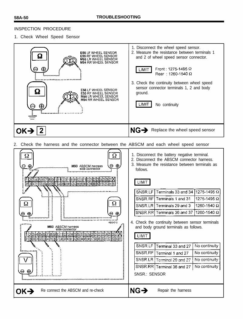
INSPECTION PROCEDURE
1. Check Wheel Speed Sensor
1. Disconnect the wheel speed sensor.2. Measure the resistance between terminals 1
and 2 of wheel speed sensor connector.
3. Check the continuity between wheel speedsensor connector terminals 1, 2 and bodyground.
No continuity
Replace the wheel speed sensor
2. Check the harness and the connector between the ABSCM and each wheel speed sensor
Re connect the ABSCM and re-check
1. Disconnect the battery negative terminal.2. Disconnect the ABSCM connector harness.3. Measure the resistance between terminals as
follows.
4. Check the continuity between sensor terminalsand body ground terminals as follows.
SNSR.: SENSOR
Repair the harness

58A-51
SPEED SENSOR CIRCUIT
At each wheel hub there is a tone wheel and an inductive sensorwhich supplies the wheel speed information to the ABSCM Thesensor comprises a magnet and a pole piece surrounded by a coil.When the tone wheel rotates adjacent to the sensor pole piece analternating current signal is generated in the coil with a frequencyproportioned to wheel speed.A special integrated circuit in the ABSCM translates the generatedAC signal to a square wave.This square wave is used by the microprocessor to operate theABS.
Code No. Scan tool display Symptom Possible cause
31 SNSR. LF-GAP Air gap ON sensor LF incorrect o Wheel speed sensor air gap32
33
SNSR. RF-GAP Air gap ON sensor RF incorrect o Wheel speed sensoro Harness or connector between the
SNSR. LR-GAP Air gap ON sensor LR incorrect wheel speed sensor and ABSCM34 SNSR. RR-GAP Air gap ON sensor RR incorrect o ABSCM
WIRING DIAGRAM

58A-52
INSPECTION PROCEDURE
1. Check Wheel Speed Sensor
1. Disconnect the wheel speed sensor.2. Measure the resistance between terminals 1
and 2 of wheel speed sensor connector.
3. Check the continuity between wheel speedsensor connector terminals 1, 2 and bodyground.
No continuity
Replace the wheel speed sensor
2. Check wheel speed sensor with scan tool
1. Connect scan tool carry out service data31 WHEEL SPEED SENSOR test by usingscan tool.
2. Drive the car about 20 kPh (12.5 mph)
18 kPh (11.25 mph) or more.

TROUBLESHOOTING 58A-53
3. Check the harness and the connector between the ABSCM and each wheel speed sensor

58A-54 TROUBLESHOOTING
SPEED SENSOR CIRCUIT
At each wheel hub there is a tone wheel and an inductive sensorwhich supplies the wheel speed information to the ABSCM Thesensor comprises a magnet and a pole piece surrounded by a coil.When the tone wheel rotates adjacent to the sensor pole piece analternating current signal is generated in the coil with a frequencyproportioned to wheel speed.A special integrated circuit in the ABSCM translates the generatedAC signal to a square wave.This square wave is used by the microprocessor to operate theABS.
Code No. Scan tool display
73
72
71
Symptom Possible cause
74
SNSR. LF-S.JMP Speed jump on the exciter wheel FL o Tone wheelSNSR. RF-S.JMP Speed jump on the exciter wheel FR o Wheel speed sensor
o Harness or connector between theSNSR. LR-S.JMP Speed jump on the exciter wheel RL wheel speed sensor and the ABSCMSNSR. RR-S.JMP Speed jump on the exciter wheel RR o ABSCM
19 TONE WHEEL Check the tone wheels o Tone wheelo Wheel speed sensor and harness
WIRING DIAGRAM

TROUBLESHOOTING 58A-55
INSPECTION PROCEDURE
1. Check Wheel Speed Sensor
1. Disconnect the wheel speed sensor2. Measure the resistance between terminals 1
and 2 of wheel speed sensor connector
3. Connect a voltmeter between the wheel speedsensor terminals, and measure the voltmeter byturning the wheel.
NOTESet the voltmeter to measure AC voltage.
AC Voltage detected
Replace wheel speed sensor
2. Check the harness and the connector between the ABSCM and each wheel speed sensor
1. Disconnect the battery negative terminal.2. Disconnect the ABSCM connector harness3. Measure the resistance between the terminals
as follows :
Re connect the ABSCM and re-check Replace wheel speed sensor
SNSR. : SENSOR

58A-56 TROUBLESHOOTING
3. Check tone wheel and sensor installation
Re connect the ABSCM and re-check
Fronto Remove the front tone wheelo Check the tone wheel teeth for missing or
scratches.
Tone wheel OK
Rear
o Check the tone wheel teeth for missing orscratches.
Tone wheel OK
ALL
o Check the air gap between the wheel speedsensors and the tone wheel teeth.
FRONT:0.2-1.1mm(0.008-0.043in.)REAR : 0.2-1.2 mm(0.008-0.047in.)
Replace the components.

TROUBLESHOOTING 58A-57
STOP LAMP SWITCH CIRCUIT
The stop lamp switch senses whether the brake pedal is depressedor released, and sends the signal to the ABSCM
INSPECTION PROCEDURE1. Check the stop light switch circuit
Re connect the ABSCM and re-check
1. Disconnect the ABSCM connector.2. Turn ignition switch to “ON” position.3. Press the brake pedal.4. Measure the voltage between terminals 15 and
27.
9.5-14.2V
Repair the harness

58A-58 TROUBLESHOOTING
DATA-LINK CIRCUIT
When a fault is detected by the ABSCM, a code is stored in theABSCM memory. The SCAN TOOL can be used to read the codesin the ABSCM memory.
INSPECTION PROCEDURE
1. Check for voltage supply of ABSCM
1. Turn ignition switch to “LOCK” position.2. Disconnect the ABSCM connector.3. Turn ignition switch to “ON” position4. Check for voltage between terminal 5 and body
ground.
9.5-14.2V
Refer to page 58A-21Power source voltage

TROUBLESHOOTING 58A-59
2. Check continuity between the ABSCM connector GND and Body GND
Check for an open between the harness and theconnector between the ABSCM and the battery
1. Turn the ignition switch to the “LOCK” position.2. Measure the ground connection between
terminal 27 and body ground, terminal 26 andbody ground, terminals 51 and body ground.
1. Check ground connection forcorrosion and loosing
2. Repair harness or connector.
3. Check for continuity between the data-link connector and the ABSCM connector

58A-60 TROUBLESHOOTING
ABSCM (ABS Control Module)
If a diagnostic trouble code is 77, replace the ABSCM.
Code No.
77
Scan tool display
ABSCM-FAIL
Symptom Possible cause
o ABSCM