anything wrong here? discussion topics--beam types 1--solid timber beam 2--built-up dimensional...
TRANSCRIPT


Anything wrong here?Anything wrong here?

Discussion Topics--Beam TypesDiscussion Topics--Beam Types
• 1--Solid timber beam• 2--Built-up dimensional lumber beam• 3--Glued Laminated beam• 4--Parallel strand lumber beam (PSL)• 5--Laminated veneer lumber beam (LVL)• 6--Truss I-Joist beam• 7--Box or Plywood beam• 8--Flitch beam (wood and steel)• 9--Steel beams

Beam Type—Solid Lumber BeamBeam Type—Solid Lumber Beam

Beam Type—Built-up Beam Type—Built-up Dimensional Lumber BeamDimensional Lumber Beam
• Dimensional lumber (2x6, 2x8, 2x10, 2x12) nailed, screwed, and/or glued together
• Vertical placement—– Large size placed
vertical

Example: Beam and Joist Example: Beam and Joist Attached with joist hangersAttached with joist hangers
• Joist are attached to beams with metal joist hangers
• What type of beam is shown?

Beam Type—Glued LaminatedBeam Type—Glued Laminated
• Dimensional lumber placed horizontally and glued together

Beam Type—Parallel Strand Beam Type—Parallel Strand (Parallam) Lumber Beam(Parallam) Lumber Beam

Beam Type—Laminated Beam Type—Laminated Veneer Lumber BeamVeneer Lumber Beam
Laminated Veneer Lumber (LVL)
Made of ultrasonically graded douglas fir veneers with exterior adhesives under heat and pressure
1 3/4” wide x (5 1/2 to 18”) depth

Beam Type—Truss I-Joist BeamBeam Type—Truss I-Joist Beam
• Laminated or Solid wood (top and bottom chords)
• OSB or Plywood web

Beam Type—Box or Plywood BeamBeam Type—Box or Plywood Beam
• 2x @ 12” or 16” structure with plywood skin
• Designed by architect or engineer

Beam Type—Flitch BeamBeam Type—Flitch Beam
• A sandwich of wood and steel
• An architect/engineer designed beam

Beam Type—Steel BeamsBeam Type—Steel Beams
S shape (American Standard shape) Often called an
I-beamW & M shapes
Wide flange design
C shapeChannel shape S--
I ShapeW or MShape
C-ChannelShape

Beam Type—Steel BeamsBeam Type—Steel Beams
• Drawing Callouts:– Shape, Nominal height x Weight/foot– Example: W10x25
NOMINAL HEIGHT
SHAPE
WEIGHT PER FOOT OF BEAM

ReactionReaction
• Reaction is the portion of the load that is transferred to the bearing points of the beam
• A simple beam reaction to a load would be at the end supports. Each end would support or be required to carry half the total load

Calculating the Reactions of a BeamCalculating the Reactions of a Beam• Total load on beam should equal
reaction loads:
– 25 x 900 = 22500#
• R1 = 15/2 x 900# = 6750#
• R2 = 10/2 x 900# = 4500#
• R3 = (15/2 + 10/2) x 900 =11250#
R2R3R1
W = 900 #/ linear foot
Span = 15’-0”
Span = 10’-0”
Reaction formula
R = wl 2 W = uniform
load l = length of span

Simple Beam DesignSimple Beam Design
• Simple beam has a uniform load evenly distributed over the entire length of the beam and is supported at each end.
• Uniform load = equal weight applied to each foot of beam.
Simple Beam DesignSimple Beam Design
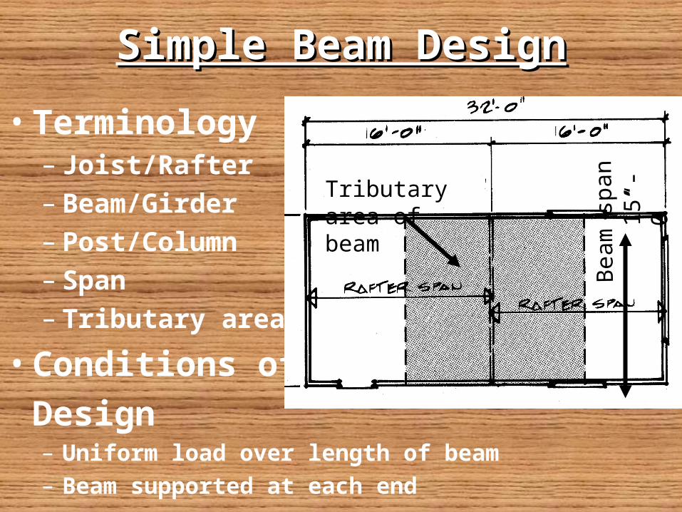
• Terminology– Joist/Rafter– Beam/Girder– Post/Column– Span– Tributary area
• Conditions of
Design– Uniform load over length of beam
– Beam supported at each end
Tributary area of beam
Bea
m s
pan
15’-
0”

Simple Beam DesignSimple Beam Design
• Tributary area– 16’ x 15’ = 240 sq ft
• Total Load on Beam– 240 x 50#/sq ft =
12,000#
• Load at each supporting end– 12,000/2 = 6000#
Bea
m s
panTributary
area of beam
15’-
0”

Table Design ConsiderationsTable Design Considerations
• Total lbs of load and span• Lbs of load per (lineal) foot• Deflection Allowances (Stiffness)
– Floor = 1/360: Meaning an allowance of 1” deflection for every 360” span, structure is solid with little deflection
– Roof = 1/240: Meaning an allowance of 1” deflection for every 240” span, structure springs or deflects more than floors

Determine the size of a Solid Determine the size of a Solid Wood Beam using Span TableWood Beam using Span Table
• 1)Determine the tributary area and calculate the total load (W) for the beam, LL = 50#, DL = 13#, therefore TL = 63# 10 x 12 x 63 = 7560 TLD
• Select beam size from table
12’-
0”
10’-0”
BEAM
20’-0”

7560 TLD w/ span of 12’
• Solution = 4 x 14 Beam
Roof Design Area 1/240
Floor Design Area 1/360

Crawl SpaceCrawl SpaceFloor Joist, Beam/PostFloor Joist, Beam/Post

Reading the Steel Table Reading the Steel Table
• Table values of load are given in kips– 1 kip = 1000 lbs
• Shape and nominal size across the top
• Weight per foot is given below designation
• Span is located along the left side of table

Example of Example of Using Steel Using Steel
TableTable
• Calculate load: 18 x 30 x 60 = 32400 TLD = 32.4 KIPS
30’-
0”
18’-0”
BEAM
•Selected Beam
S18 x 54.7

Glued-Laminated Beam TableGlued-Laminated Beam TableDesign Data: Span 18’, Load per linear feet = 674#

Columns and PostColumns and Post

Reading Column TablesReading Column Tables
• Determine the column load
• Establish the height of column
• Set the column size by height and load

Steel Column TableSteel Column TableConditions: Height = 4.5’, Load = 19.4 kips
Solution: 2 ½ Dia x 5.79 PIPE COLUMN

Wood Post TableWood Post TableConditions: Height = 4 feet, Load = 23,000
Solution: 4x6 WOOD POST

Load ConsiderationsLoad Considerations
• First floor loads (DL + LL) = 50#/sq ft
• First floor partitions (DL) = 10#/sq ft
• Second floor loads (DL + LL) = 50#/sq ft
• Second floor partitions (DL) = 10#/sq ft
• If Truss design no loads on interior structure(DL)
• If rafter/ceiling joist design (DL) = 20#/sq ft
• Roof load regionally varies (LL) = 20-50#/sq ft

Beam Sizing Beam Sizing and Post and Post SpacingSpacing
Trial & Error Method1--Locate tributary area
2--Determine various conditions placing post to shorten the beam span
3--Go to tables & choose beam
4--Smaller beams are less expensive and usually better

Handout on Structural Handout on Structural Analysis #2Analysis #2
• Before doing calculations sketch problem to visualize conditions
• Calculate the tributary loads for beams and columns conditions
• Use Handout charts and tables and select beams and columns for conditions
