ao-a 030 35«r the dynamics and thermodynamics of compressible fluid flow,, vol. ii, bonald press,...
TRANSCRIPT

AO-A 030 35«r UMDM|MMI*S[
nil inn MH. M^M,
5 0712 01010519 4
o i-H O
QO
AD bRL REPORT NO. 1919
ACOUSTIC THERM0METRIC MEASUREMENTS OF
PR0PELLANT GAS TEMPERATURES IN GUNS
Edward M. Schmidt Edmund J. Gion Donald D. Shear
TECHNICAL LIBRARY
August 1976
Approved for public release; distribution unlimited.
!yTIC QUALITY INSPECTED 8
USA BALLISTIC RESEARCH LABORATORIES ABERDEEN PROVING GROUND, MARYLAND
19971009 072

Destroy this report when it is no longer needed. Do not return it to the originator.
Secondary distribution of this report by originating or sponsoring activity is prohibited.
Additional copies of this report may be obtained from the National Technical Information Service, U.S. Department of Commerce, Springfield, Virginia 22151.
»
The findings in this report are not to be construed as an official Department of the Army position, unless so designated by other authorized documents.

UNCLASSIFIED SECURITY CLASSIFICATION OF THIS PAGE (When Dmta Entered)
REPORT DOCUMENTATION PAGE READ INSTRUCTIONS BEFORE COMPLETING FORM
I. REPORT NUMBER
BRL Report No. 1919
2. GOVT ACCESSION NO 3. RECIPIENT'S CATALOG NUMBER
4. TITLE (end .Subtitle)
ACOUSTIC THERMOMETRIC MEASUREMENTS OF PROPELLANT GAS TEMPERATURES IN GUNS
5. TYPE OF REPORT ft PERIOD COVERED
Final
6. PERFORMING ORG. REPORT NUMBER
7. AUTHORfe)
Edward M. Schmidt, Edmund J. Gion, and Donald D. Shear
8. CONTRACT OR GRANT NUMBERS
9. PERFORMING ORGANIZATION NAME AND ADDRESS
USA Ballistic Research Laboratories Aberdeen Proving Ground, Maryland 21005
10. PROGRAM ELEMENT. PROJECT. TASK AREA a. WORK UNIT NUMBERS
RDT§E 1W161102AH43
It. CONTROLLING OFFICE NAME AND ADDRESS
U.S. Army Materiel Development § Readiness Command 5001 Eisenhower Avenue Alexandria, Virginia 22333
12. REPORT DATE
AUGUST 1976 13. NUMBER OF PAGES
31 14 MONITORING AGENCY NAME 4 ADDRESSf// different tram Controlling Office,) IS. SECURITY CLASS, (ol thlm report)
UNCLASSIFIED I5«. DECLASSIFI CATION/DOWNGRADING
SCHEDULE
16. DISTRIBUTION STATEMENT (ol this Report)
Approved for public release; distribution unlimited.
17. DISTRIBUTION STATEMENT (ol the abstract entered In Block 20, ft dlllerent from Report)
18. SUPPLEMENTARY NOTES
19. KEY WORDS (Continue on reveree eide it neceemary and identity by block number)
Interior Ballistics Muzzle Blast Propellant Gas Temperature
20. ABSTRACT (Continue on reverem aide It neceeemry end Identity by block number) (l1QT^\
A technique is developed which permits propellant gas temperature to be ex- tracted from pressure measurements taken within the gun tube. Basically similar to acoustic thermometry, the wave speed of a signal propagating at the sonic velocity is determined. In this application, the speed of the expansion wave which propagates back up the gun tube following shot ejection is derived from pressure data taken at discrete axial locations within four calibers of the muzzle of a 20mm gun. The propellant gas temperature is calculated from the measured speed of this wave and the equation of statft.
DO,, FORM
AN 73 1473 EDITION OF t NOV 65 IS OBSOLETE UNCLASSIFIED
SECURITY CLASSIFICATION OF THIS PAGE (When Data Entered)

TABLE OF CONTENTS
Page
LIST OF ILLUSTRATIONS 5
I. INTRODUCTION 7
II. INSTRUMENTATION AND EXPERIMENTAL DATA 9
III. DATA REDUCTION AND PRESENTATION 11
IV. CONCLUSIONS 14
REFERENCES 24
LIST OF SYMBOLS 25
DISTRIBUTION LIST 27

LIST OF ILLUSTRATIONS
Figure Page
1. Shadowgraph of Muzzle Blast 16
2. Idealized, One-Dimensional Exit Flow 17
3. Ratio of Energy Efflux Rates Versus Incident Flow Mach Number 17
4. In-bore Wave Diagram 18
5. Schematic of Test Set-up 18
6. Muzzle Adaptor 19
7. Sample Pressure Traces at u = 366 m/s 20 m
8. Pressure Traces from Gauge 3 at Various Launch Velocities 21
9. Wave Diagram of Muzzle Flow 22
10. Measured Speed of Sound 22
11. Measured Exit Pressure 23
12. Measured Exit Temperature 23
I. INTRODUCTION
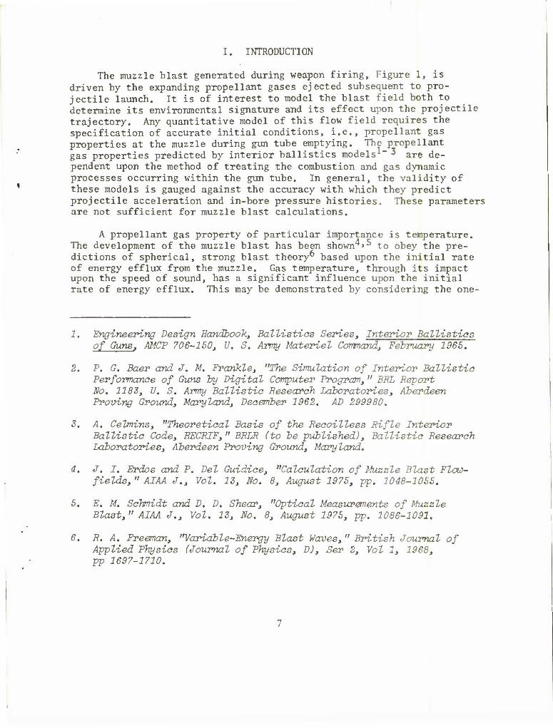
The muzzle blast generated during weapon firing, Figure 1, is driven by the expanding propellant gases ejected subsequent to pro- jectile launch. It is of interest to model the blast field both to determine its environmental signature and its effect upon the projectile trajectory. Any quantitative model of this flow field requires the specification of accurate initial conditions, i.e., propellant gas properties at the muzzle during gun tube emptying. The propellant gas properties predicted by interior ballistics models1" * are de- pendent upon the method of treating the combustion and gas dynamic processes occurring within the gun tube. In general, the validity of these models is gauged against the accuracy with which they predict projectile acceleration and in-bore pressure histories. These parameters are not sufficient for muzzle blast calculations.
A propellant gas property of particular importance is temperature. The development of the muzzle blast has been shown'*'^ to obey the pre- dictions of spherical, strong blast theory" based upon the initial rate of energy efflux from the muzzle. Gas temperature, through its impact upon the speed of sound, has a significant influence upon the initial rate of energy efflux. This may be demonstrated by considering the one-
1. Engineering Design Handbook Ballistics Series, Interior Ballistics of Guns, AMCP 706-1503 U. S. Army Materiel Command, February 1965.
2. P. G. Baer and J. M. Frankle, "The Simulation of Interior Ballistic Performance of Guns by Digital Computer Program, " BEL Beport No. 1183; U. S. Army Ballistic Research Laboratories, Aberdeen Proving Ground, Maryland, December 1962. AD 299980.
3. A. Celmins, "Theoretical Basis of the Recoilless Rifle Interior Ballistic Code, RECRIF," BRLR (to be published), Ballistic Research Laboratories, Aberdeen Proving Ground, Maryland.
4. J. I. Erdos and P. Del Guidice, "Calculation of Muzzle Blast Flow- fields," AIAA J., Vol. 13, No. 8, August 1975, pp. 1048-1055.
5. E. M. Schmidt and D. D. Shear, "Optical Measurements of Muzzle Blast," AIAA J., Vol. 13, No. 8, August 1975, pp. 1086-1091.
6. R. A. Freeman, ''Variable-Energy Blast Waves, " British Journal of Applied Physics (Journal of Physics, D), Ser 2, Vol 1, 1968, pp 1697-1710.

dimensional flow of an ideal gas. The energy flux past any station at a given time is
u2 E = pu (cvT + —) A
= pu Yi^ll (u 2 A> (1)
y-1 2 a
Neglecting the projectile presence and two dimensional effects, the idealized flow geometry shown in Figure 2 is used to approximate the arrival of the propellant gases at the muzzle and subsequent expansion of these gases once the muzzle is breached. Using one-dimensional, un- steady flow theory', an expression for the ratio of incident rate of energy flux, EL, to rate of energy passing the muzzle, E*, may be derived which is only a function of the ratio of specific heats and incident Mach number, u-./a... For y = 1.25, this ratio is plotted versus u^a.
in Figure 3. The energy flux ratio, E*/E1, varies strongly with
incident Mach number in the range 0 < u^a. <_ 0.6. As the sonic condi-
tion is approached, the energy flux ratio asymptotes toward unity due to decreasing strength of the muzzle expansion. For sonic and super- sonic values of u^a., there is obviously no return expansion from the
muzzle. Since several important classes of weapons (e.g.: mortars, howitzers) launch projectiles in the low incident Mach number regime, it is of interest to determine the detailed exit properties under these conditions.
A variety of techniques has been applied to the measurement of propellant gas temperature during the interior ballistic cycle. Thermocouples^ have been mounted to the inner wall of the gun tube in attempting to directly measure gas temperature. Since flush mounted devices are immersed in the propellant gas boundary/thermal layer, thermocouple output does not reflect temperature in the inviscid main stream. Optical techniques such as two-color pyrometry" and
7. A. H. Shapiroj The Dynamics and Thermodynamics of Compressible Fluid Flow,, Vol. II, Bonald Press, N.Y., 19S4.
8. G. S. Fulcher, "The Temperature of the Bore Surface of Guns," NDBC B A-201, National Defense Besearch Committee, July 1943.
9. F. C. Kracek and W. S. Benedict, "An Ecperimental Study of Powder Gas Badiation and Temperature, " NDBC B A-252, National Defense Besearch Committee, February 1944.

spectroscopy1^'11 are also complicated by the presence of the wall boundary layer. Additionally, contamination of optical surfaces by particulate deposition during the measurement period further degrade these approaches. Klingenberg and MachU present a calibration and data acquisition procedure which reduces the influence of this deposi- tion on spectroscopic measurements; however, the effect of the wall thermal layer remains to be assessed.
In the present report, a novel method to obtain in-bore tempera- ture measurements is presented. The approach is similar to that used in acoustic thermometryl2; namely, the velocity of propagation of an acoustic wave is determined by measuring the time required for it to travel a known distance. Unlike acoustic thermometry in which an external signal is introduced into the test medium, the present tech- nique measures the propagation velocity of an isentropic wave which is generated in the flow itself, the returning muzzle expansion, Figure 4. Pressure transducers, flush mounted in the tube wall, are used to sense passage of the muzzle expansion. Since pressure signals are impressed across the wall boundary layer, its affects upon the measurements are minimized. The details of the instrumentation and data reduction pro- cedures applied to a 20mm gun will be presented in the subsequent sections.
II. INSTRUMENTATION AND EXPERIMENTAL DATA
A schematic of the test set-up is shown in Figure 5. Data is taken on the launch of a standard,. 98 gram, training projectile from a 20mm gun. The gun has a length of 152cm, chamber volume of 41.7cm3, and twist of one turn in 25 calibers. A summary of launch velocities obtained by loading the cartridge with different weights of WC870 powder is shown in Table I. Launch velocity was measured from flash X-rays taken at three stations covering the first 60cm of projectile flight.
10. G. Klingenberg and H. Mach, "Spektroskopische Temperaturbestimmung im unmittelbaren Mundugsbereich H-ines Gewehres, " ABF B 4/74, Arbeitsgruppe fur Ballistische Forschung, Veil am Rhein, Germany, December 1974.
11. G. Klingenberg and H. Mach, "Experimental Study of Non-Steady Phenomena Associated with the Combustion of Solid Gun Propellants," presented at the Sixteenth International Symposium on Combustion, Boston, Massachusetts, August 1976.
12. L. C. Lynnworth and E. H. Carnevale, "Ultrasonic Thermometry Using Pulse Techniques," in: Temperature, Its Measurement and Control in Science and Industry, Vol.4, H. H. Plumb,ed., Instrument Society of America, Pittsburgh, 1972, pp 715-732.
9

Mc(Kg X 103) 3.56 5.76 8.10 10.04 12.63 18.15 22.02 25.93 33.33
um(m/s) 265 325 385 450 540 605 680 765 910
TABLE I: LAUNCH CONDITIONS
A muzzle adaptor, having an overall length of 8.6cm, Figure 6, was fabricated to accommodate and shock mount the array of pressure trans- ducers. The adaptor bore diameter is 21mm to permit projectile clear- ance of the gauge surfaces. Since the weapon groove diameter is 20.75mm, there is a 0.25mm clearance between the projectile rotating band and the adaptor bore surface. Including the contribution of the nine lands, there is a 4.3 percent increase in cross sectional area between the gun and adaptor bores. Assuming a sonic flow is generated in the annulus between the projectile and adaptor surfaces, the resulting change in the flow properties behind the projectile may be approximated using steady flow theory. This calculation shows the temperature and pressure decrease by 0.01 percent and 0.04 percent, respectively. Such property variations are not significant in the current experiments which are intended to prove the viability of the measurement technique. The active transducers are three Kistler, 603A, piezo-electric, pressure transducers spaced at 2.5cm intervals from the front face of the device. The outputs of the transducers are recorded on Tektronix, Type 551, Dual-Beam Oscilloscopes. A uniform time base between traces is provided by triggering all scopes simultaneously from the output of gauge 1 as the projectile passes. Additionally, the discharge of the first X-ray tube is placed on each oscilloscope record by chopping the lower beam. In this manner, the projectile location may be related to the measured pressure variations.
A sample set of pressure traces obtained for a launch velocity of 366 m/s is shown in Figure 7. As the projectile passes gauge 1, all scopes are triggered simultaneously. When the projectile passes a gauge location, there is a rapid pressure rise as the gauge becomes exposed to the high pressure propellant gases. Naturally, gauge station 1 is exposed first followed by stations 2 and 3. As the projectile moves down the tube, in-bore waves reflected from the breech and the projectile base pass the gauge location. This results in a gradual decay of the measured pressure at the gauge station.
When the projectile clears the muzzle, the propellant gases expand into the surrounding atmosphere. Simultaneously, an expansion propagates into the gun tube bringing the muzzle to a choked or sonic condition. As the expansion passes the gauge station, the pressure begins to decrease more rapidly. This is clearly observed as the sudden change in slope on the pressure traces. The wave is propagating into the gun tube; thus, it arrives first at station 3 and then moves
10

to stations 2 and 1. The difference in arrival times is evident from the three traces shown in Figure 7. Since station 3 is closest to the center of the muzzle expansion, the rate of change of properties occurs very rapidly. As the muzzle expansion propagates further into the gun, it spreads out; thus the change in slope of the pressure traces is less severe. It is desirable to locate the pressure gauges as near to the muzzle as possible in order to minimize property variation due to in-bore waves and to provide a strong signal upon passage of the muzzle expansion. This is particularly true at high launch veloc- ities, Figure 8. As the launch velocity increases, pressure decay due to in-bore waves arriving prior to the muzzle expansion becomes more severe. Simultaneously, the strength of the muzzle expansion decreases. In the limiting case, the launch velocity increases to a point where the propellant gas reaches a sonic condition prior to shot ejection. When this occurs, there is no muzzle expansion into the gun tube.
III. DATA REDUCTION AND PRESENTATION
A wave diagram of the near muzzle region is shown in Figure 9. The goal of this technique is to determine the velocity of propagation of the lead wave of the muzzle expansion, m-f-d-b. The instantaneous velocity of a left running wave is
c = £ = u - a, (2)
where u and a are the local flow velocity and speed of sound, respectively, The most direct means to obtain an estimate of the speed of sound is to assume the flow velocity is constant and equal to the launch velocity, u , evaluate the wave speed using the measured arrival times at the
gauge stations, and invert Equation (2);
VX1 a = Um-t7t7 ' •
t b
This approach does not account for property variations occurring prior to arrival of the muzzle expansion as evidenced by pressure decay in Figure 8.
A correction procedure may be developed from one-dimensional flow theory7 if the flow is assumed to be locally isentropic within test region, a-m-b. The following relation describes the property variations along a left running characteristic or within a region of right running simple waves:
11

where the subscript, 1, refers to a suitable reference point. For isentropic flow,
2y
v a Y_1
I = Cf-D (5) pi ai
These relations apply along the lead expansion wave, m-f-d-b; however, there is no pressure gauge exactly at the muzzle. This restricts the location of the initial reference point to be point e. The pressure- time history along the path e-f-d-b may be obtained from the measured data (pressures from e-f come directly from the trace of the third gauge, pressures at d and b come from the intercept values on traces 2 and 1).
If the projectile velocity is assumed to remain constant over the last 2.5cm of travel through the device, u = u , and if the path e-f
6 in
is approximated as a simple wave region, Equation (4) may be used to derive the following relation:
(6) u a
u i m ( 3-Y a 2 a a a y-1 a Y-1 e e e e
Substituting Equation (5),
Y-1
H_ . 2_ . jn + 3-Y ,£> _ _2_ () a a a Y-1 lP J Y-1 l J e e e ' re '
From Equation (2), the incremental displacement, dx, of the lead wave in time, dt, is
dx = (u-a) dt
Y-1 2Y 2a
Cu + =-L £-] a ?) dt, (8) v m Y-1 P e Y-1 e
12

This expression may be integrated over the path of the wave, f-d-b, and inverted to solve for a ,
Y-l
"**
tb 2y (AX-U At)/(H * ft-] dt - -=rr At) , (9) v m " Y-l t- Lp J Y-l e v m ^ V-l t,. lp J Y-l f re
where Ax = x, - xf ,
At = t. - t- . b f
All of the terms in Equation (9) may be obtained from the pressure traces. The resulting correction to the speed of sound is small for low launch velocities; however, at 800 m/s, the value of a obtained
from Equation (9) is fifteen percent lower than the speed of sound obtained from direct differencing, Equation (3).
The variation in speed of sound with launch velocity obtained by this method is presented in Figure 10. For launch velocities between 200 and 600 m/s, the speed of sound of the propellant gas prior to shot ejection remains constant at 675 m/s with a scatter of plus or minus 20 m/s in the data. Subsequent to the 600 m/s launch velocity, the propellant gas speed of sound begins to increase rapidly reaching a sonic value at a launch velocity of 780 m/s. Further variations in the speed of sound with launch velocity may not be measured using the present technique.
The pressure measured at gauge station 3 immediately after pro- jectile passage is plotted as a function of launch velocity in Figure 11. The muzzle pressure shows an almost linear variation with velocity until 600 m/s when it increases suddenly. After the dis- continuous jump, the pressure again increases linearly. This sudden increase in muzzle pressure occurs at the same launch velocity at which the speed of sound begins to increase; thus, suggesting the possibility of a change in the combustion process. The design launch velocity of the round is 1000 m/s. Lower velocities were obtained by simply removing propellant from the cartridge case without reducing the chamber volume. The propellant was held against the ignitor in the rear of the cartridge by a thin diaphragm. The free volume thus generated between the propellant bed and the base of the projectile may permit the establishment of pressure waves affecting the subsequent combustion history of the propellant.
The propellant gas temperature is computed from the measured sound speed by assuming the applicability of an equation of state. In the present case, it is assumed that by the time the propellant gases expand to the muzzle, they may be treated as an ideal gas. The
15

muzzle temperature may be evaluated from
2 l
where
T - £_ , (10)
Y = 1.25,
R = 365.5 m2/s2 °K .
The temperature evaluated from the measured sound speed is shown in Figure 12. At low launch velocities, the muzzle temperature remains roughly constant with a value of 1000°K. Subsequent to 600 m/s, the temperature increases to a maximum value of 1320°K at 800 m/s.
The present measurements are compared with the predictions of a closed form solutionl and numerical integration^ of the interior ballistics of the 20mm gun. The closed form solution, based on the Mayer-Hart System, requires input of empirical values of projectile velocity and muzzle pressure for each launch condition. The numerical solution requires adjusting of the friction and burning rate coeffi- cients to produce a match to the measured muzzle pressure and launch velocity at 1000 m/s. Subsequent solutions are extrapolated from this match condition. In both cases, the theoretical solutions predict temperature variations with launch velocity which are opposite to the measured trends. Agreement between theory and experiment occur only at a single intercept point. It should be noted that the "wiggle" in the Mayer-Hart solution occurs due to its reliance upon empirical input which possess discontinuities, Figure 11. Also shown in Figure 12 is the result of a spectroscopic measurement by Klingenberg and Mach11. Their measurement was obtain immediately behind a 20mm projectile as it passed an optical window located 120cm from the breech. This data point compares well with the results of the current technique taken at a station 158cm from the breech of a 20mm gun.
IV. CONCLUSIONS
A procedure is developed which permits the determination of propellant gas temperature immediately behind the projectile at shot ejection. Pressure gauges are used to observe the time of passage of the muzzle expansion at a known location. A differencing relation is presented to calculate the speed of sound of this wave. In- corporated in this relation are corrections to account for changes in speed of sound and flow velocity over the measurement period.
14

Figure 1. Shadowgraph of Muzzle Blast
lb

The procedure is used to determine the propellant gas temperature at the muzzle of a 20mm gun over a range of launch velocities. Compari- son of the measured temperature with simple interior ballistic analyses shows poor agreement indicating the need for continued investigation. Studies are being initiated to resolve this descrepancy. The results of the present technique are shown to compare favorably with spectro- scopic temperature measurements obtained on a similar gun.
15

t=o
"* t>o
^«.
Figure 2. Idealized, One-Dimensional Exit Flow
5r
E I 2
J L
U./0, .6 .8 1.0
Figure 3. Ratio of Energy Efflux Rates Versus Incident Flow Mach Number
17

MUZZLE EXPANSION
••X /////////////////////////////////////////////////////111,!
Figure 4. In-bore Wave Diagram
£
fl fl fl
j 2 3 h~ 30 cm -4— 30 cm —J
nlll'
X-RAY HEADS
rr—i—7—/////////////i FILM
Figure 5. Schematic of Test Set-up
18

Figure 6. Muzzle Adaptor
19

STATION 1
STATION 2
STATION 3
Figure 7. Sample Pressure Traces at u = 366 m/s
20

um = 247 m/s
u = 366 m/s
u = 469 m/s
um = 542 m/s
u = 634 m/s
um = 758 m/s
Figure 8. Pressure Traces from Gauge 3 at Various Launch Velocities
21

t
GAUGE I
Figure 9. Wave Diagram of Muzzle Flow
800
E 700 h
<D
600 0 200 400 600 800 1000
um (m/s)
Figure 10. Measured Speed of Sound
22

200 r
160
120
0
6 0)
8>
e/r rco 80
40
© 6>
6» cS
<5>
_L 200 400 600
um(m/s) 800 1000
1800
1600
Figure 11. Measured Exit Pressure
BAER & FRANKLE,REF.2
1400
T/K)
1200
1000
800
MAYER-HART.REF.I
d? X*' Q OCURRENT RESULTS
SPECTROSCOPIC, e1
o0O«)0o8
8° ° REF. II
± j
200 400 600 800 1000
Um(m/s)
Figure 12. Measured Exit Temperature
23

REFERENCES
1. Engineering Design Handbook, Ballistics Series, Interior Ballistics of Guns, AMCP 706-150, U. S. Army Materiel Command, February 1965.
2. P. G. Baer and J. M. Frankle, "The Simulation of Interior Ballistic Performance of Guns by Digital Computer Program," BRL Report No. 1183, U. S. Army Ballistic Research Laboratories, Aberdeen Proving Ground, Maryland, December 1962. AD 299980.
3. A Celmins, "Theoretical Basis of the Recoilless Rifle Interior Ballistic Code, RECRIF," BRLR (to be published), Ballistic Research Laboratories, Aberdeen Proving Ground, Maryland.
4. J. I. Erdos and P. Del Guidice, "Calculation of Muzzle Blast Flow- fields," AIAA J., Vol. 13, No. 8, August 1975, pp. 1048-1055.
5. E. M„ Schmidt and D. D. Shear, "Optical Measurements of Muzzle Blast," AIAA J., Vol. 13, No. 8, August 1975, pp. 1086-1091.
6. R. A. Freeman, "Variable-Energy Blast Waves," British Journal of Applied Physics (Journal of Physics, D), Ser 2, Vol 1, 1968, pp 1697-1710.
7. A. H. Shapiro, The Dynamics and Thermodynamics of Compressible Fluid Flow, Vol. II, Ronald Press, N.Y., 1954.
8. G. S. Fulcher, "The Temperature of the Bore Surface of Guns," NDRC R A-201, National Defense Research Committee, July 1943.
9. F. C. Kracek and W. S. Benedict, "An Experimental Study of Powder Gas Radiation and Temperature," NDRC R A-252, National Defense Research Committee, February 1944.
10. G. Klingenberg and H. Mach, "Spektroskopische Temperaturbestimmung im unmittelbaren Mundugsbereich Eines Gewehres," ABF R 4/74, Arbeitsgruppe fur Ballistische Forschung, Weil am Rhein, Germany, December 1974.
11. G. Klingenberg and H. Mach, "Experimental Study of Non-Steady Phenomena Associated with the Combustion of Solid Gun Propellants," presented at the Sixteenth International Symposium on Combustion, Boston, Massachusetts, August 1976.
12. L. C. Lynworth and E. H. Carnevale, "Ultrasonic Thermometry Using Pulse Techniques," in: Temperature, Its Measurement and Control in Scinece and Industry, Vol. 4, H. H. Plumb, ed., Instrument Society of America, Pittsburgh, 1972, pp 715-732.
24

LIST OF SYMBOLS
a speed of sound
A area
Cv specific heat at constant volume
c wave speed
• E rate at which energy passes a given point
P pressure
R gas constant
t time
T temperature
u velocity
X axial coordinate
•y ratio of specific heats
25

DISTRIBUTION LIST
No. of Copies
12
Organization
Commander Defense Documentation Center ATTN: DDC-TCA Cameron Station Alexandria, VA 22314
Director Defense Nuclear Agency Washington, DC 20305
1 Commander US Army Materiel Development
and Readiness Command ATTN: DRCDMA-ST 5001 Eisenhower Avenue Alexandria, VA 22333
1 Commander US Army Materiel Development
and Readiness Command ATTN: DRCDL 5001 Eisenhower Avenue Alexandria, VA 22333
3 Commander US Army Aviation Systems
Command ATTN: DRSAV-E
DRSAV-EQA, CPT Schrage DRCPM-AAH, G. Smith
12th and Spruce Streets St. Louis, MO 63166
1 Director US Army Air Mobility Research
and Development Laboratory Ames Research Center Moffett Field, CA 94035
1 Commander US Army Electronics Command ATTN: DRSEL-RD Fort Monmouth, NJ 07703
No. of Copies Organization
1 Commander US Army Jefferson Proving Ground ATTN: STEJP-TD-D Madison, IN 47250
4 Commander US Army Missile Command ATTN: DRSMI-R
DRSMI-RBL DRSMI-RDK
Mr. R. Becht Mr. R. Deep
Redstone Arsenal, AL 35809
1 Commander US Army Tank Automotive
Development Command ATTN: DRDTA-RWL Warren, MI 48090
2 Commander US Army Mobility Equipment
Research $ Development Command ATTN: Tech Docu Cen, Bldg. 315
DRSME-RZT Fort Belvoir, VA 22060
4 Commander US Army Armament Command ATTN: P. Ehle
E. Haug Technical Lib DRSAR-RDG, J. Blick
Rock Island, IL 61202
2 Commander US Army Armament Command ATTN: Rodman Laboratories
S. Thompson S. Burley
Rock Island, IL 61202
27

DISTRIBUTION LIST
No. of No. of Copies Organization Cop ies Organization
8 Commander 2 Commander US Army Frankford Arsenal US Army Harry Diamond Labs ATTN: Mr. T. Boldt ATTN: DRXDO-TI
SARFA-U2100 DRXDO-DAB, H.J. Davis Mr. J. Mitchell 2800 Powder Mill Road
SARFA-U3100, S. Fulton Adelphi, MD 20783 SARFA-73300
Mr. S. Hirshman Mr. A. Cianciosi
L4100-150-2 Mr. C. Sleischer, Jr.
SARFA-MDS-D 220 F. Puzycki C. Rueter
Philadelphia, PA 19137
Commander US Army Picatinny Arsenal ATTN: SARPA-DR-D, S. Wasserman
SARPA-DR-V, Mr. A. Loeb Mr. D. Mertz Mr. F. Friedman
SARPA-D, Mr. Lindner Dover, NJ 07801
Commander US Army Picatinny Arsenal ATTN: SARPA-C, E. Walbrecht
Mr. S. Verner SARPA-VE, Dr. Kaufman SARPA-FR-M-MA
Mr. E. Barrieres SARPA-PA-S, W.Dzingala
Dover, NJ 07801
Commander US Army Watervliet Arsenal ATTN: Tech Lib
SARWV-PDR-S, F. Sautter SARWV-PDR-AMM
Dr. J. Zweig SARWV-RDD-SE, P.A. Alto
Watervliet, NY 12189
1 Commander US Army Materials and
Mechanics Research Center ATTN: DRXMR-ATL Watertown, MA 02172
1 Commander US Army Natick Research and
Development Command ATTN: DRXRE, Dr. D. Sieling Natick, MA 01762
1 Director US Army TRADOC Systems
Analysis Activity ATTN: ATAA-SA White Sands Missile Range NM 88002
1 Commander US Army Research Office ATTN: CRD-AA-EH P. 0. Box 12211 Research Triangle Park NM 27709
1 Director US Army BMD Advanced
Technology Center P.O. Box 1500, West Station Huntsville, AL 35807
1 Commander US Army Ballistic Missile
Defense Systems Command Huntsville, AL 35804
28

DISTRIBUTION LIST
No. of Copies
<•
» *
Organization
Commander US Naval Air Systems Command ATTN: AIR-604 Washington, DC 20360
Commander US Naval Ordnance Systems
Command ATTN: ORD-9132 Washington, DC 20360
2 Commander and Director David W. Taylor Naval Ship
Research & Development Center ATTN: Tech Lib
Aerodynamic Lab Bethesda, MD 20084
3 Commander Naval Surface Weapons Center ATTN: Code 312, Mr. F. Regan
Mr. S. Hastings Code 730, Tech Lib
Silver Spring, MD 20910
3 Commander US Naval Surface Weapons Center ATTN: Code GX, Dr. W. Kemper
Mr. F. H. Maille Dr. G. Moore
Dahlgren, VA 22448
1 Commander US Naval Weapons Center ATTN: Code 553, Tech Lib China Lake, CA 93555
3 Director US Naval Research Laboratory ATTN: Tech Info Div
Code 7700, D. A. Kolb Code 7720, Dr.E.McClean
Washington, DC 20390
No. of Copies Organization
Commander US Naval Ordnance Station ATTN: Code FS13A, P. Sewell Indian Head, MD 20640
AFRPL/LKCB (Dr. Horning) Edwards AFB, CA 93523
ADTC (ADBPS-12) Eglin AFB, FL 32542
AFATL (DLDL) Eglin AFB, FL
AFATL (DLRA, F. Tech Lib
Eglin AFB, FL
32542
Burgess;
32542
AFWL (DEV) Kirtland AFB, NM 87117
ASD (ASBEE) Wright-Patterson AFB, OH 45433
Director NASA Scientific § Technical
Information Facility ATTN: SAK/DL P. 0. Box 8757 Baltimore/Washington International Airport, MD 21240
Director Jet Propulsion Laboratory ATTN: Tech Lib 2800 Oak Grove Drive Pasadena, CA 91103
Director National Aeronautics and
Space Administration George C. Marshall Space
Flight Center ATTN: MS-I, Lib
R-AERO-AE, A. Felix Huntsville, AL 35812
29

DISTRIBUTION LIST
No. of Copies Organization
Director National Aeronautics and
Space Administration Langley Research Center ATTN: MS 185, Tech Lib Langley Station Hampton, VA 23365
AAI Corporation ATTN: Dr. T. Stastny Cockeysville, MD 21030
1 Advanced Technology Laboratories ATTN: Dr. J. Erdos Merrick § Stewart Avenues Westbury, NY 11590
1 Aerospace Corporation ATTN: Dr. T. Taylor P. 0. Box 92957 Los Angeles, CA 90009
2 ARO, Inc. ATTN: Tech Lib Arnold AFS, TN 37389
1 ARTEC Associates, Inc. ATTN: Dr. S. Gill 26046 Eden Landing Road Hayward, CA 94545
1 AVCO Systems Division ATTN: Dr. W. Reinecke 201 Lowell Street Wilmington, MA 01887
1 Calspan Corporation ATTN: Mr. G. A. Sterbutzel P. 0. Box 235 Buffalo, NY 14221
1 Technical Director Colt Firearms Corporation 150 Huyshore Avenue Hartford, CT 14061
No. of Copies Organization
General Electric Corporation Armaments Division ATTN: Mr. R. Whyte Lakeside Avenue Burlington, VT 05401
Martin Marietta Aerospace ATTN: Mr. A. J. Culotta P. 0. Box 5387 Orlando, FL 32805
Northrop Corporation Aircraft Division ATTN: Dr. A. Wortman 3901 W. Broadway Hawthorne, CA 90250
1 Winchester-Western Division Olin Corporation New Haven, CT 06504
1 Sandia Laboratories ATTN: Aerodynamics Dept
Org 5620, R. Maydew P. 0. Box 5800 Albuquerque, NM 87115
1 S$D Dynamics Inc. ATTN: Dr. M. Soifer 755 New York Avenue Huntington, NY 11743
1 Guggenheim Aeronautical Laboratory
California Institute of Technology
ATTN: Tech Lib Pasadena, CA 91104
2 Franklin Institute ATTN: Dr. Carfagno
Dr. Wachtell Race $ 20th Streets Philadelphia, PA 19103
30

No. of Copies Organization
DISTRIBUTION LIST
No. of Copies Organization
1 Director Applied Physics Laboratory The Johns Hopkins University Johns Hopkins Road Laurel, MD 20810
1 Massachusetts Institute of Technology
Department of Aeronautics and Astronautics
ATTN: Tech Lib 77 Massachusetts Avenue Cambridge, MA 02139
1 Ohio State University Department of Aeronautics
and Astronautical Engineering ATTN: Tech Lib Columbus, OH 43210
2 Polytechnic Institute of Brooklyn
Graduate Center ATTN: Tech Lib
Dr. G. Moretti Farmingdale, NY 11735
1 Princeton University Forrestal Campus Library P. 0. Box 710 Princeton, NJ 08540
1 Southwest Research Institute ATTN: Mr. Peter S. Westine P. 0. Drawer 28510 8500 Culebra Road San Antonio, TX 78228
Aberdeen Proving Ground
Marine Corps Ln Ofc Dir, USAMSAA
ATTN: Dr. J. Sperrazza Cdr, USAEA
ATTN: A. Flatau, SAREA-DE-W Bldg. E3516
51