“simulink models of faulty induction machines for …summary “simulink models of faulty...
TRANSCRIPT
Cracow University of Technology
Department of Electrical and Computer Engineering Institute of Electromechanical Energy Conversion, E-2
“Simulink models of faulty induction
machines for drives applications”
SUMMARY OF DOCTORAL DISSERTATION
BY Alejandro Fernández Gómez, M.Sc.
Supervisor: Dr. Hab. Konrad Weinreb
Kraków 2015
Summary “Simulink models of faulty induction machines for drives applications”
Page 2
PhD Thesis Brief
Objectives
The aim of the research is to develop mathematical model of squirrel cage induction motors and to create
dynamic models in Matlab/Simulink ready to be implemented in drive applications. Following the classical model
of IM, faulty models can also be reduced to a system of four electrical equation, two equations either for stator
and rotor currents, and two mechanical equations. The use of models with a reduce number of equations will
reduce the simulation time (Despite of the fact that technology is improving incredible fast the time require to
run a simulation is still an important constrain to be taken into consideration).
Mathematical models of squirrel cage induction motor have been simplified considering tree phase rotor
windings as the configuration of a slip-ring induction motor. The rotor bar currents are not accessible, the
diagnosis of the fault is mainly conducted by studying the stator phase currents in different reference frames
applying Motor Current Signature Analysis techniques. Therefore, the rotor currents are not being subject to any
analysis. Theoretically, the effects of the rotor quantities and the physical phenomena inside the rotor cause the
same effect over the stator phase currents in both configurations of the induction motor.
The simplification is as follows: in case of considering the squirrel cage rotor the number of rotor currents to be
defined is equal to the number of bars plus one extra current which represent the current flowing through one
of the rings. The magneto-motive force (MMF) in each of the mesh is also approximated by a sinusoidal function
with small amplitude due to the fact that it depends on the angle between bars 𝛾 = 2 ∗ 𝑝𝑖/𝑁. Instead to
considering each independent mesh current the bars have been grouped in three sets and only one mesh current
has been considered. The sum of all MMFs along the rotor bars in both cases will be equivalent leading to the
same effects over the stator phase currents.
The objectives are listed below:
- Develop a Matlab/Simulink Library of faulty dynamic induction motor models for diagnosis purposes
- Design a test-bench and a data acquisition system
- Validation of simulation results with experimental data
- Apply advance signal processing techniques to the data stored
- Explore the suitability of these models for diagnosis of faults
In the market there are many software tools which offer friendly user interfaces and tools for modelling electrical
systems. However, Matlab/Simulink has been chosen due to the fact that offers the possibility of C and Hardware
Description Language (HDL) code generation and the compatibility it has with many industrial solutions.
The most important outcome of the research is to have a library of exchangeable models to investigate new
control laws that improve the ability of drives to control the induction motor. In the course of the thesis, it will
be proved, that despite the assumptions made, the models are suitable for studying the behavior of a fault by
means of MCSA techniques, widely used by the scientific community, supported by experimental results.
Summary “Simulink models of faulty induction machines for drives applications”
Page 3
Cele
Celem badań jest opracowanie modeli matematycznych silników indukcyjnych klatkowych i stworzenie modeli
dynamicznych z użyciem oprogramowania Matlab/Simulink, gotowych do stosowania w aplikacjach
napędowych. Zgodnie z klasycznym modelem silnika indukcyjnego, modele silnika z wadą również mogą być
sprowadzone do układu czterech równań: dwóch równań napięć stojana lub wirnika oraz dwóch równań
mechanicznych. Zastosowanie modeli ze zmniejszoną liczbą równań zmniejsza również czas potrzebny na
symulacje (pomimo bardzo szybkiego rozwoju i ciągłego ulepszania technologii, czas wymagany do
przeprowadzenia symulacji wciąż stanowi ważne ograniczenie, które musi zostać wzięte pod uwagę).
Modele matematyczne klatkowego silnika indukcyjnego zostały uproszczone przez przyjęcie trójfazowego
uzwojenia wirnika, jak w silniku pierścieniowym. Prądy w prętach wirnika nie są dostępne, a diagnoza
uszkodzenia jest przeprowadzana głównie poprzez badanie prądów fazowych stojana w różnych układach
odniesienia z zastosowaniem techniki MCSA. Dlatego też prądy wirnika nie są poddane żadnej analizie.
Teoretycznie, wpływ właściwości wirnika oraz zjawisk fizycznych zachodzących w jego wnętrzu na fazowe prądy
stojana jest taki sam w obydwu konfiguracjach silnika indukcyjnego.
Uproszczenie prowadzi do następującego spostrzeżenia: w przypadku silnika klatkowego liczba zdefiniowanych
prądów wirnika jest równa liczbie prętów, plus dodatkowo prąd, który reprezentuje prąd przepływający przez
jeden z pierścieni zwierających.
Siła magnetomotoryczna (MMF) w każdym z oczek klatki jest również aproksymowana funkcją sinusoidalną o
małej amplitudzie ze względu na fakt, iż zależy ona od kąta nachylenia pomiędzy prętami 𝛾 = 2𝜋/𝑁. Zamiast
rozważać prąd pojedynczego oczka, pręty zostały zebrane w trzy grupy, reprezentowane przez tylko jeden prąd
oczkowy w grupie. Suma wszystkich sił magnetomotorycznych wzdłuż prętów wirnika w obu przypadkach
będzie równa, co ma taki sam wpływ na fazowe prądy stojana.
Poniżej wymienione są cele badawcze:
- stworzenie biblioteki modeli dynamicznych uszkodzonych silników indukcyjnych za pomocą
oprogramowania Matlab/Simulink dla celów diagnostycznych
- zaprojektowanie stanowiska pomiarowego i systemu zbierania danych
- walidacja wyników symulacji z użyciem danych doświadczalnych
- zastosowanie zaawansowanych technik przetwarzania sygnałów na przechowywanych danych
- zbadanie adekwatności opracowanych modeli do celów diagnostycznych
Na rynku znajduje się wiele narzędzi oprogramowania, które oferują przyjazne użytkownikowi interfejsy i
narzędzia modelowania systemów elektrycznych. Niemniej jednak, dla celów tej pracy badawczej wybrano
narzędzie Matlab/Simulink, jako że oferuje możliwość generacji kodu C i HDL (Hardware Description Language)
oraz ze względu jego kompatybilność, z wieloma rozwiązaniami stosowanymi w przemyśle (w rozdziale drugim
przedstawione zostaną zalety wyboru programu Matlab/Simulink).
Najważniejszym wynikiem pracy badawczej jest stworzenie biblioteki wymiennych modeli w celu zbadania
nowych przepisów kontrolnych, które poprawiają zdolność napędów do kontroli silników indukcyjnych. W
ramach poniższej pracy zostanie udowodnione, że pomimo poczynionych założeń, modele te nadają się do,
Summary “Simulink models of faulty induction machines for drives applications”
Page 4
wspieranego przez wyniki doświadczalne, badania specyfiki danego uszkodzenia za pomocą technik MCSA,
powszechnie stosowanych przez środowiska naukowe.
Chapter Summary
The thesis has been structured as follows:
- Chapter 2 – State of Art: the common faults in IM will be described as well as the main signal processing
techniques. A review of the main contributions in the field of induction motor fault diagnosis and the
suitability of Matlab for modelling electromechanical systems are also discussed.
- Chapter 3 – Modelling electrical machines under fault condition: dynamic faulty machine models have
been developed following the winding function approach. The chapter will guide the lector through the
mathematical procedure. An explanation of the physical phenomena occurring inside the machine for
each fault will be described from the point of view of mathematics.
- Chapter 4 – Harmonic Balance Method: it is a method of steady-state analysis for electrical machine
equations with periodic coefficients which consists of a linear system of algebraic equations. The
method takes into consideration the physical phenomena inside the machine when it is affected by a
fault and their effects on the harmonic content of the stator currents. It is equivalent to the symbolic
calculus for electric circuits.
- Chapter 5 – Test Bench Set-up: it includes a description of the lab equipment used and the estimation of
the IM parameters.
- Chapter 6 – Matlab-Simulink Implementation of Dynamic IM Models: the Simulink model performance
is analyzed supported by simulation results.
- Chapter 7 – Matlab Implementation of Steady State IM Models: the Matlab model performance is
analyzed supported by simulation results.
- Chapter 8 – Experimental Results - Validation of Simulation Results: discussion about the simulation
results for different operation points of the induction motor validated by experimental data of dynamic
and steady state models.
- Chapter 9 – Drives Applications with Faulty Induction Motor models: Implementation into a Zynq all
programmable System on a Chip (SoC) (ARM+FPGA): practical case of model implementation. It shows
the results of the work carried out at ABB Corporate Research Center Poland as part of the task planned
within the Energy Smartops project.
- Chapter 10 – Analysis and Diagnosis of Electrical and Mechanical Faults in Induction Motors: it contains
a summary of the research work published by the author of the thesis in the field of fault diagnosis of
induction motors.
- Chapter 11 – Conclusions
State of Art
The main techniques used to diagnose fault on electrical machines has been discussed. Some of them are
mentioned below:

Summary “Simulink models of faulty induction machines for drives applications”
Page 5
1. Stator Faults: the common techniques used to diagnose faults in stator are [10]:
a. Magnetic Flux: a measure of the axial flux can reveal distortion of the air-gap flux or comparing
the voltages across different stator coils.
b. Rotor speed: studying the magnitude variations of the 100 Hz frequency component.
c. Temperature: degradation of the insulation material cause increased in losses. A detection of
hot spots in the stator core is used to detect such problems [15].
d. Stator currents: as it has been shown in table III the stator defects add frequency components
to the stator currents [19].
2. Rotor Faults – Broken bar detection: Detection of BBs typically performed studying the low-frequency
sidebands around the main component, i. e., the relation of the sideband magnitudes as fault indicator,
is not always effective [9]. High frequency components around the 3th, 4th, 5th, 7th and PSH harmonics
can be useful [1] [5] [12] [16]. The FFT is the basic analysis but it has some disadvantages such as the
need of knowing the motor speed, the confusion with mechanical fault or spectra leakage. In such
situations, WT or HT are a good solution to overcome those disadvantages [18]. In the following section
some of the research work done in this area is summarized.
3. Rotor Faults – Eccentricity detections: The difficulty in detecting types of eccentricities stems from the
fact that SE and DE usually appear simultaneously. Both types of eccentricities add similar additional
frequencies making it difficult to tell the difference between them. Moreover, not all frequency
components will appear in each motor (they depend on the number of rotor bars). Another difficulty is
that those frequencies can appear due to other fault types. Several models have been proposed in
literature [2] [3] [4] [6] [8] [11] [17] including all or main harmonics. For instance, each author had a
particular way of calculating the geometrical length of the air-gap in order to approximate the value of
the permenace function to the real one accounting for stator/rotor slots, saturation or simply the Carter
coefficient. Many of the analysis conducted in this field are based in the comparison of the low/high
frequency magnitudes well known in literature establishing different indexes with the aim of either
distinguish faults or detecting the severity level.
Finally, the suitability of MATLAB/SIMULINK as simulation software is also discussed:
Nowadays MATLAB/SIMULINK offers an integrated environment to simulate the transient and steady state of
electrical machines with time-varying variables under different conditions which allow the simulation of a large
number of operation modes. An important advantage of that package is the waveform representation of
electrical signals. The simple fact of knowing the equations is not enough to obtain results successfully. This
software requires a hard effort in understanding the procedure of resolution of differential equations.
In this Thesis, MATLAB/SIMULINK has been used to create a toolbox of Faulty Induction Motor models for
analysis and fault diagnosis purposes due to the fact that it is a software with extensive use in the teaching and
engineering field. It provides many toolboxes related to signal processing techniques, Digital Signal Processor
(DSP) programming and it offers compatibility with DAQ devices from many manufactures. Moreover it allows
creating and customizing user interfaces for easy visualization of model results and/or organization of simulation
Summary “Simulink models of faulty induction machines for drives applications”
Page 6
options for non-expert programmer users. Many publications have shown Simulink models for
implementation of IM [7] [13] [14] [17]; nevertheless, only the healthy machine has been studied.
Modelling Electrical Machines under Fault Condition
This chapter explains the methodology followed to develop dynamic induction motor models under fault
condition: Lagrange function and Winding Function Approach (WFA). The different physical phenomena that
occur inside the machine when it is affected by faults are analyzed by mathematical equations leading to models
with different levels of complexity. These models can be reduced to two sets of electrical and mechanical
equations following the classical model of IM by applying specific transformation matrices widely known by the
scientific community with the exception of the Mixed Eccentricity (ME) model.
Lagrange Equation and Winding Function Approach
The interaction of the stator and rotor magnetic fields is the fundamental mechanism by which the electrical
energy is converted into mechanical energy and vice versa in IMs. Since failures produces a distortion of the
magnetic fields it may seem logic to develop algorithms which describes the distribution of the magnetic field in
the machine an use software based on FEM to detect faults in IMs. Nevertheless, this type of analysis requires
solving Laplace and Poisson’s equations which is a time consuming process. As fault diagnosis of IMs is mainly
based on the study of the harmonic content of currents, fluxes torque and/or speed, the development of models
based on groups of magnetic circuits’ couple each other, provides a better alternative to understand the physical
phenomena associated with failures and the fault consequences in the IM’s variables. Those electromagnetic
circuits are composed by a set of resistance and inductance matrices.
Electromechanical converters such as induction motors can be mathematically described by Hamilton’s and
Lagrange’s functions but in practice only Lagrange equation is used as Hamilton’s development is much more
complicated.
Assuming the linearity of the magnetic circuit, the converter equations following the Lagrange’s functions are
as follows:
𝑑
𝑑𝑡(𝑳(𝜑) ∙ 𝒊) + 𝑹 ∙ 𝒊 = 𝒖 (3. 1)
𝐽𝑑2𝜑
𝑑𝑡+ 𝐷
𝑑𝜑
𝑑𝑡=
1
2∙ 𝒊𝑇 ∙
𝑳(𝜑)
𝜕𝜑∙ 𝒊 + 𝑇𝑚 (3. 2)
Winding Function Approach (WFA) is a method for estimation of the machine inductances and for the geometry
definition of the air-gap. The inductances values are calculated as function of the linked flux along the air-gap of
the machine, which is defined by so-called permeance function. This method has some limitation due to the fact
that following assumptions have to be taken:
- Linear magnetic field
- The magnetic material has infinite permeance
- Fluxes crossed the air-gap radially
- Eddy and Hysteresis currents are neglected

Summary “Simulink models of faulty induction machines for drives applications”
Page 7
In addition it has been assumed that saturation and slotting effects are also neglected.
In order to obtain the magnetic field distribution is needed to define the MMF function of all windings. The MMF
is quasi periodic, hence, it can be represented by Fourier series. For distributed coils in stator the general form
used for the MMF function is:
𝜃(𝑥, 𝑡) = 𝑖(𝑡) ∙ ∑4
𝜋∙𝑤 ∙ 𝑘𝜌
2 ∙ 𝜌
∞
𝜌=1
∙ cos 𝜌(𝑥 − 𝛼) (3.3)
where “𝑖(𝑡)” is the current flowing through the coil, “𝑘𝜌” is the winding factor, “𝑤” is number of winding turns,
“𝜌” the order of the harmonic and “𝛼” is the angle between coils.
The permeance function depends on the magnetic circuit type and defines the geometry of the air-gap along the
circumference. One important property of the permeance function is that is a periodic function. λ(𝑥, 𝜑) is the
inverse of the air-gap length:
λ(𝑥, 𝜑) =1
δ(𝑥, 𝜑) (3. 4)
A new function is introduced: The Ampere-turn function 𝑤(𝑥, 𝑡) based on MMF function.
w(x, 𝑡) =1
𝑖(𝑡)∙𝑑𝜃(𝑥, 𝑡)
𝑑𝑥= ∑ (−
2
𝜋)𝑤𝑘𝜌 sin 𝜌(𝑥 − 𝛼𝜌)
∞
𝜌=1
(3. 5)
The final expression for linked flux of the winding “n” due to magnetic field forced by the winding “k” for “𝜌”
harmonic is as follows:
Ψ𝑛,𝑘 = 𝑟 ∙ 𝑙 ∙ ∑ (∫ (∑ (−2
𝜋)𝑤𝑛𝑘𝑛,𝜌 sin 𝜌(𝑥 − 𝛼𝜌)
𝜌
𝑚=1
)𝛼𝑛,𝜌
𝛼𝑛,𝜌−𝜋𝜌
∙ ∫ B𝑘(𝜍, 𝜑, 𝑡)𝑑𝛼𝑘,𝑚
𝛼𝜌,𝑚
𝜍)𝑑𝑥
∞
𝜌=1
(3. 6)
Inductance values are obtained as,
L𝑛,𝑘 = Ψ𝑛,𝑘
/i𝑛 (3. 7)
In addition, there is another type of inductance left: the Leakage inductance. In a real machine part of the linked
flux do not cross the air-gap, for instance, those lines that encircle only the stator and rotor coils (bars).
The linked fluxes can be classified in:
- Stator and rotor slot leakage inductance
- Zig-zag leakage inductance
- Differential leakage inductance
- End connection leakage inductance
- Skewing leakage inductance
Generally, total leakage inductance is accounted as the 10% of the self-inductance.
It may happens that the machine inductance depends on the rotation angle “𝜑”. With the aim of simplified the
calculations following transformation matrices are used to eliminate such dependence. As a result, the converter
equations can be reduced to a system of differential equations with constant coefficient matrices. When
applying these transformation matrices, the zero sequence of the symmetrical components can be neglected. If
the steady state of the machine is considered, for a given speed, the converters equations are even reduced to
a set of simply lineal equations by means of the Harmonic Balance Method (HBM) explained in next chapter.
Equation 3.1 and 3.2 can be expressed in matrix form:
Summary “Simulink models of faulty induction machines for drives applications”
Page 8
[𝑼𝒔
𝑼𝒓] = [
𝑹𝒔 00 𝑹𝒓
] ∙ [𝑰𝒔
𝑰𝒓] +
𝑑
𝑑𝑡[𝑳𝒔,𝒔(𝜑) + 𝑳𝒔
𝝈 𝑳𝒔,𝒓(𝜑)
𝑳𝒓,𝒔(𝜑) 𝑳𝒓,𝒓(𝜑) + 𝑳𝒓𝝈] ∙ [
𝑰𝒔
𝑰𝒓] (3. 8)
𝐽𝑑2𝜑
𝑑𝑡+ 𝐷
𝑑𝜑
𝑑𝑡= 𝑇𝑒𝑙𝑒𝑐 + 𝑇𝑚 =
1
2∙ [(𝑰𝒔)
𝑇 (𝑰𝒓)𝑇] ∙
[ 𝑳𝒔,𝒔(𝜑)
𝜕𝜑
𝑳𝒔,𝒓(𝜑)
𝜕𝜑𝑳𝒓,𝒔(𝜑)
𝜕𝜑
𝑳𝒓,𝒓(𝜑)
𝜕𝜑 ]
∙ [𝑰𝒔
𝑰𝒓] + 𝑇𝑚 (3. 9)
For all the dynamic models develop on the thesis, the inductances and resistances are changed according the
fault. For instance, when it comes to model broken bars, 𝑹𝒓 is substitute for and equivalent matrix, 𝑹𝒆𝒒, that
contains the asymmetry and symmetry coefficients, 𝑘𝑎𝑠 & 𝑘𝑠, well known among the research community.
The following models with faults has been created: 1/ Cage Asymmetry; 2/ Static Eccentricity; 3/ Dynamic
Eccentricity; 4/ Simulation of Mechanical faults.
Moreover, the electromagnetic torque, 𝑇𝑒𝑙𝑒𝑐, will depend on the transformation matrices applied as well.
Examples of Final Induction motor Models Following the WFA
3.2.1 Modelling Induction motor Mechanical Faults: Eccentricities
The Eccentricity is inherited to the electrical machine. It occurs when the air-gap is not constant, which means,
the distance between the inner-circumference of the stator and the outer circumference of the rotor is not
constant. In fact that happens since the stator and rotor are built with slots to allocate the windings.
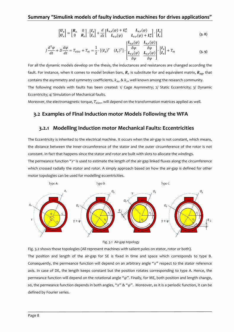
The permeance function “𝜆” is used to estimate the length of the air-gap linked fluxes along the circumference
which crossed radially the stator and rotor. A simply approach based on how the air-gap is defined for other
motor topologies can be used for modelling eccentricities.
Fig. 3.2 shows those topologies (All represent machines with salient poles on stator, rotor or both).
The position and length of the air-gap for SE is fixed in time and space which corresponds to type B.
Consequently, the permeance function will depend on an arbitrary angle “𝑥” respect to the stator reference
axis. In case of DE, the length keeps constant but the position rotates corresponding to type A. Hence, the
permeance function will depend on the rotational angle “𝜑”. Finally, for ME, both position and length change,
s0, the permeance function depends in both angles, “𝑥” & “𝜑”. Moreover, as it is a periodic function, it can be
defined by Fourier series.
Summary “Simulink models of faulty induction machines for drives applications”
Page 9
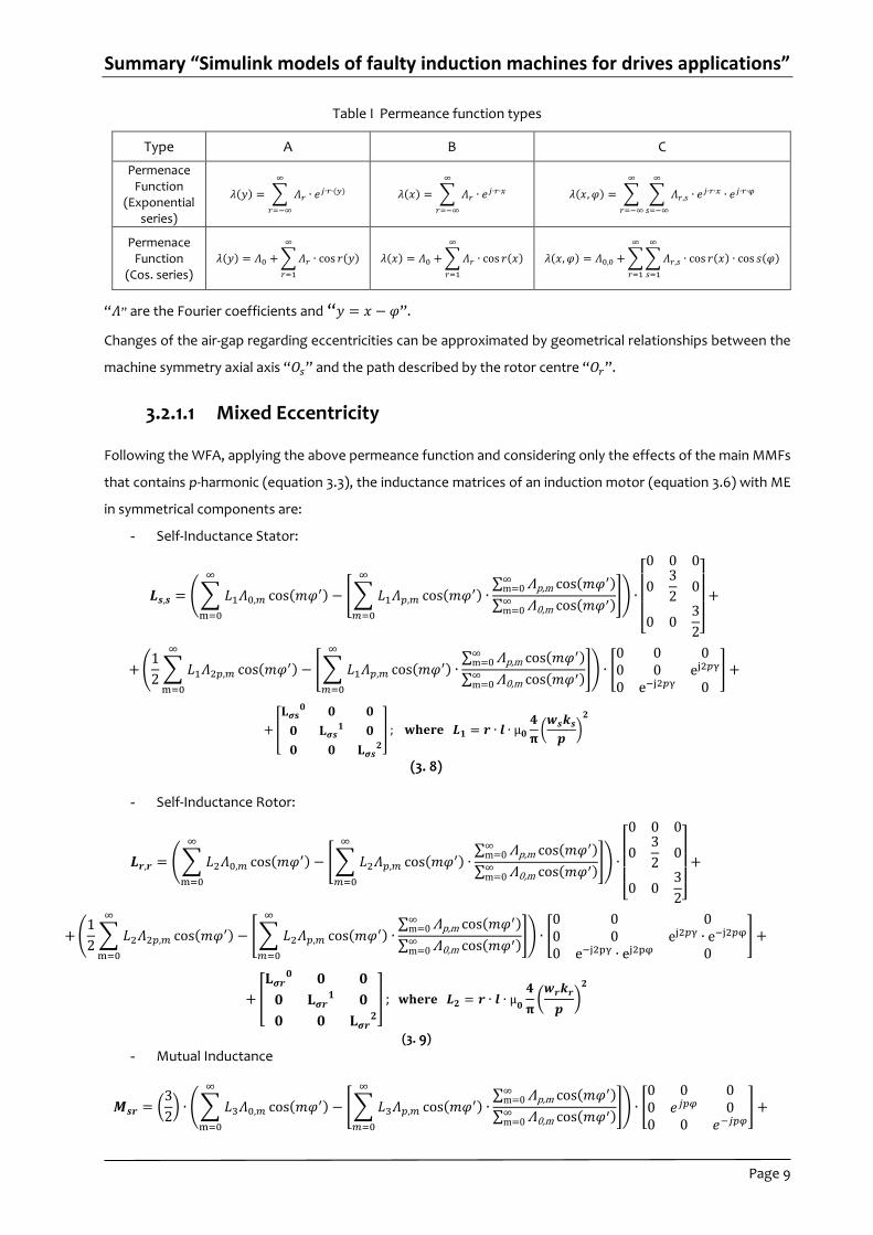
Table I Permeance function types
Type A B C
Permenace Function
(Exponential series)
𝜆(𝑦) = ∑ 𝛬𝑟 ∙ 𝑒𝑗∙𝑟∙(𝑦)
∞
𝑟=−∞
𝜆(𝑥) = ∑ 𝛬𝑟 ∙ 𝑒𝑗∙𝑟∙𝑥
∞
𝑟=−∞
𝜆(𝑥, 𝜑) = ∑ ∑ 𝛬𝑟,𝑠 ∙ 𝑒𝑗∙𝑟∙𝑥 ∙ 𝑒𝑗∙𝑟∙𝜑
∞
𝑠=−∞
∞
𝑟=−∞
Permenace Function
(Cos. series)
𝜆(𝑦) = 𝛬0 + ∑𝛬𝑟 ∙ cos 𝑟(𝑦)
∞
𝑟=1
𝜆(𝑥) = 𝛬0 + ∑𝛬𝑟 ∙ cos 𝑟(𝑥)
∞
𝑟=1
𝜆(𝑥, 𝜑) = 𝛬0,0 + ∑∑𝛬𝑟,𝑠 ∙ cos 𝑟(𝑥) ∙ cos 𝑠(𝜑)
∞
𝑠=1
∞
𝑟=1
“𝛬” are the Fourier coefficients and “𝑦 = 𝑥 − 𝜑”.
Changes of the air-gap regarding eccentricities can be approximated by geometrical relationships between the
machine symmetry axial axis “𝑂𝑠” and the path described by the rotor centre “𝑂𝑟”.
3.2.1.1 Mixed Eccentricity
Following the WFA, applying the above permeance function and considering only the effects of the main MMFs
that contains p-harmonic (equation 3.3), the inductance matrices of an induction motor (equation 3.6) with ME
in symmetrical components are:
- Self-Inductance Stator:
𝑳𝒔,𝒔 = (∑ 𝐿1𝛬0,𝑚 cos(𝑚𝜑′)
∞
m=0
− [∑ 𝐿1𝛬𝑝,𝑚 cos(𝑚𝜑′)
∞
𝑚=0
∙∑ Λp,m cos(𝑚𝜑′)∞
m=0
∑ Λ0,m cos(𝑚𝜑′)∞m=0
]) ∙
[ 0 0 0
03
20
0 03
2]
+
+(1
2∑ 𝐿1𝛬2𝑝,𝑚 cos(𝑚𝜑′)
∞
m=0
− [∑ 𝐿1𝛬𝑝,𝑚 cos(𝑚𝜑′)
∞
𝑚=0
∙∑ Λp,m cos(𝑚𝜑′)∞
m=0
∑ Λ0,m cos(𝑚𝜑′)∞m=0
]) ∙ [0 0 00 0 ej2𝑝γ
0 e−j2𝑝γ 0] +
+[
𝐋𝝈𝐬𝟎 𝟎 𝟎
𝟎 𝐋𝝈𝒔𝟏 𝟎
𝟎 𝟎 𝐋𝝈𝒔𝟐
] ; 𝐰𝐡𝐞𝐫𝐞 𝑳𝟏 = 𝒓 ∙ 𝒍 ∙ µ𝟎
𝟒
𝛑(𝒘𝒔𝒌𝒔
𝒑)𝟐
(3. 8)
- Self-Inductance Rotor:
𝑳𝒓,𝒓 = (∑ 𝐿2𝛬0,𝑚 cos(𝑚𝜑′)
∞
m=0
− [∑ 𝐿2𝛬𝑝,𝑚 cos(𝑚𝜑′)
∞
𝑚=0
∙∑ Λp,m cos(𝑚𝜑′)∞
m=0
∑ Λ0,m cos(𝑚𝜑′)∞m=0
]) ∙
[ 0 0 0
03
20
0 03
2]
+
+(1
2∑ 𝐿2𝛬2𝑝,𝑚 cos(𝑚𝜑′)
∞
m=0
− [∑ 𝐿2𝛬𝑝,𝑚 cos(𝑚𝜑′)
∞
𝑚=0
∙∑ Λp,m cos(𝑚𝜑′)∞
m=0
∑ Λ0,m cos(𝑚𝜑′)∞m=0
]) ∙ [0 0 00 0 ej2𝑝γ ∙ e−j2𝑝φ
0 e−j2pγ ∙ ej2pφ 0] +
+[
𝐋𝝈𝒓𝟎 𝟎 𝟎
𝟎 𝐋𝝈𝒓𝟏 𝟎
𝟎 𝟎 𝐋𝝈𝒓𝟐
] ; 𝐰𝐡𝐞𝐫𝐞 𝑳𝟐 = 𝒓 ∙ 𝒍 ∙ µ𝟎
𝟒
𝛑(𝒘𝒓𝒌𝒓
𝒑)
𝟐
(3. 9)
- Mutual Inductance
𝑴𝒔𝒓 = (3
2) ∙ (∑ 𝐿3𝛬0,𝑚 cos(𝑚𝜑′)
∞
m=0
− [∑ 𝐿3𝛬𝑝,𝑚 cos(𝑚𝜑′)
∞
𝑚=0
∙∑ Λp,m cos(𝑚𝜑′)∞
m=0
∑ Λ0,m cos(𝑚𝜑′)∞m=0
]) ∙ [0 0 00 𝑒𝑗𝑝𝜑 00 0 𝑒−𝑗𝑝𝜑
] +
Summary “Simulink models of faulty induction machines for drives applications”
Page 10
+(1
2∑ 𝐿3𝛬2𝑝,𝑚 cos(𝑚𝜑′)
∞
m=0
− [∑ 𝐿3𝛬𝑝,𝑚 cos(𝑚𝜑′)
∞
𝑚=0
∙∑ Λp,m cos(𝑚𝜑′)∞
m=0
∑ Λ0,m cos(𝑚𝜑′)∞m=0
]) ∙3
2∙ [(
0 0 00 0 𝑒−𝑗𝑝𝜑+𝑗2𝑝γ
0 𝑒𝑗𝑝𝜑−𝑗2𝑝γ 0) ] +
where 𝐿3 = 𝑟 ∙ 𝑙 ∙ µ0
1
π∙ (
𝑤𝑠𝑘𝑠
𝑝) (
𝑤𝑟𝑘𝑟
𝑝)
(3. 10)
Harmonic Balance Method
In the previous chapter it has been shown that the converter’s equations can be reduced to two sets of four
electrical and two mechanical linear differential equations with constant coefficients periodic matrices. Classical
method based on circuit theory can easily solve the system in analytical form. Furthermore, if the steady state
of the machine is considered, which means that the solution of the mechanical equation is known, the system
can be reduced to linear equations.
A method for steady state analysis of electrical machines with non-linear differential equations with periodic
coefficient is presented for those cases in which the transformation matrix does not obtain matrices with
constant coefficients: “Harmonic Balance Method” (HBM). This methodology has been applied to determine the
steady state of an induction motor affected by ME. Additionally, models for SE and DE has also been created to
compare with dynamic models obtained from WFA. They have accounted the main MMFs and the presence of
air-gap asymmetry which cause the appearance of additional harmonics of magnetic permeance assuming linear
magnetic circuit, three symmetrical stator and rotor windings, “p” pair of poles and there phase rotor mesh
currents. Moreover, the same assumptions made in order to obtain a dynamic model of IM are also assumed.
Model of all the eccentrities are listed below, where:
- Ω𝑜 and Ω are the angular velocity of the net and rotor
- 𝑬 is the identity matrix
- 𝑳𝒔𝒔𝟎 , 𝑴𝒔𝒓
𝟎 , 𝑰𝒓 , 𝑰𝒔 , 𝑼𝒔 and 𝑼𝒓 are matrices with the self and mutual inductance, stator and rotor currents
and voltages values associated to inductance, current and voltage harmonics
- 𝑅𝑠 and 𝑅𝑟 the stator and rotor resistances
In the bellow equations, indexes of factors (inductances and currents) are strictly defined and correspond to the
algebraic multiple of the angular velocity.
Summary “Simulink models of faulty induction machines for drives applications”
Page 11
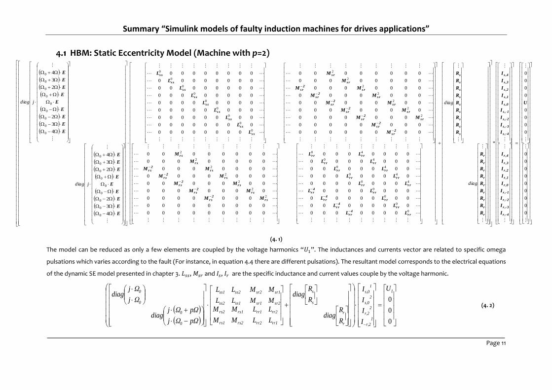
HBM: Static Eccentricity Model (Machine with p=2)
0
0
0
0
0
0
0
0
0
0
0
0
0
0
0
0
0
*
0000000
0000000
0000000
0000000
0000000
0000000
0000000
0000000
0000000
000000000
000000000
0000000
0000000
0000000
0000000
0000000
00000000
00000000
00000000
00000000
0000000
0000000
0000000
0000000
0000000
00000000
00000000
00000000
00000000
00000000
00000000
00000000
00000000
00000000
00000000
00000000
4
3
2
2
3
4
4
3
2
2
3
4
0
0
0
0
40
40
40
40
40
2
2
2
2
2
2
2
2
2
2
2
2
2
2
0
0
0
0
0
0
0
0
0
0
0
0
0
0
0
0
0
0
0
0
0
0
0
0
0
0
0
U
I
I
I
I
I
I
I
I
I
I
I
I
I
I
I
I
I
I
R
R
R
R
R
R
R
R
R
R
R
R
R
R
R
R
R
R
LL
LL
LL
LL
LL
LL
LL
LL
LL
MM
MM
MM
MM
MM
M
M
M
M
MM
MM
MM
MM
MM
M
M
L
L
L
L
L
L
L
L
L
E
E
E
E
E
E
E
E
E
E
E
E
E
E
E
E
E
E
4r ,
3r ,
2r ,
1r ,
r ,0
r ,1
r ,2
r ,3
r ,4
4s ,
3s ,
2s ,
1s ,
s ,0
s ,1
s ,2
s ,3
s ,4
r
r
r
r
r
r
r
r
r
s
s
s
s
s
s
s
s
s
r r4
r r
r r4
r r
r r4
r r
r r4
r r
r rr r
r rr r
r rr r
r rr r
r rr r
r s2
r s
r s2
r s
r s2
r s
r s2
r s
r s2
r s
r s
r s
2s r
2s r
s r2
s r
s r2
s r
s r2
s r
s r2
s r
s r2
s r
s r
s r
s s
s s
s s
s s
s s
s s
s s
s s
s s
diag
diag
jdiag
jdiag
(4. 1)
The model can be reduced as only a few elements are coupled by the voltage harmonics “𝑈1”. The inductances and currents vector are related to specific omega
pulsations which varies according to the fault (For instance, in equation 4.4 there are different pulsations). The resultant model corresponds to the electrical equations
of the dynamic SE model presented in chapter 3. 𝐿𝑠𝑠, 𝑀𝑠𝑟 and 𝐼𝑠, 𝐼𝑟 are the specific inductance and current values couple by the voltage harmonic.
0
0
0
1
1
r,2
2
r,2
2
s,0
1
s,0
r
r
s
s
rr1rr2
rr2rr1
rs2rs1
rs1rs2
sr2sr1
sr1sr2
ss1ss2
ss2ss1
0
0
0
0U
I
I
I
I
R
Rdiag
R
Rdiag
LL
LL
MM
MM
MM
MM
LL
LL
pΩΩj
pΩΩjdiag
Ωj
Ωjdiag
(4. 2)
Summary “Simulink models of faulty induction machines for drives applications”
Page 12
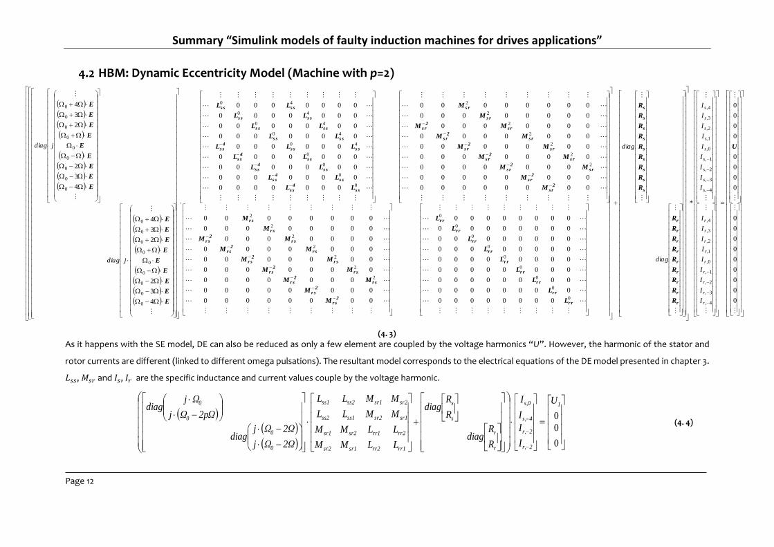
HBM: Dynamic Eccentricity Model (Machine with p=2)
As it happens with the SE model, DE can also be reduced as only a few element are coupled by the voltage harmonics “U”. However, the harmonic of the stator and
rotor currents are different (linked to different omega pulsations). The resultant model corresponds to the electrical equations of the DE model presented in chapter 3.
𝐿𝑠𝑠, 𝑀𝑠𝑟 and 𝐼𝑠, 𝐼𝑟 are the specific inductance and current values couple by the voltage harmonic.
0
0
0
1
2r,
2r,
4s,
s,0
r
r
s
s
rr1rr2sr1sr2
rr2rr1sr2sr1
sr1sr2ss1ss2
sr2sr1ss2ss1
0
0
0
0 U
I
I
I
I
R
Rdiag
R
Rdiag
LLMM
LLMM
MMLL
MMLL
2ΩΩj
2ΩΩjdiag
2pΩΩj
Ωjdiag
(4. 4)
0
0
0
0
0
0
0
0
0
0
0
0
0
0
0
0
0
*
00000000
00000000
00000000
00000000
00000000
00000000
00000000
00000000
00000000
00000000
00000000
0000000
0000000
0000000
0000000
0000000
00000000
00000000
00000000
00000000
0000000
0000000
0000000
0000000
0000000
00000000
00000000
0000000
0000000
0000000
0000000
000000
0000000
0000000
0000000
0000000
4
3
2
2
3
4
4
3
2
2
3
4
4,
3,
2,
1,
0,
1,
2,
3,
4,
4,
3,
2,
1,
0,
1,
2,
3,
4,
0
0
0
0
0
0
0
0
0
2
2
2
2
2
2
2
2
2
2
2
2
2
2
0
0
0
0
40
40
40
40
40
0
0
0
0
0
0
0
0
0
0
0
0
0
0
0
0
0
0
U
R
R
R
R
R
R
R
R
R
R
R
R
R
R
R
R
R
R
L
L
L
L
L
L
L
L
L
M
M
MM
MM
MM
MM
MM
M
M
M
M
MM
MM
MM
MM
MM
M
M
LL
LL
LL
LL
LLL
LL
LL
LL
LL
E
E
E
E
E
E
E
E
E
E
E
E
E
E
E
E
E
E
r
r
r
r
r
r
r
r
r
s
s
s
s
s
s
s
s
s
r r
r r
r r
r r
r r
r r
r r
r r
r r
2r s
2r s
r s2
r s
r s2
r s
r s2
r s
r s2
r s
r s2
r s
r s
r s
2s r
2s r
s r2
s r
s r2
s r
s r2
s r
s r2
s r
s r2
s r
s r
s r
s s4
s s
s s4
s s
s s4
s s
s s4
s s
s ss s4
s s
s ss s
s ss s
s ss s
s ss s
r
r
r
r
r
r
r
r
r
s
s
s
s
s
s
s
s
s
I
I
I
I
I
I
I
I
I
I
I
I
I
I
I
I
I
I
diag
diag
jdiag
jdiag
(4. 3)
Summary “Simulink models of faulty induction machines for drives applications”
Page 13
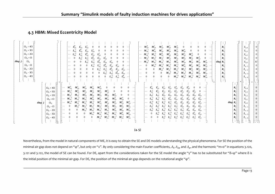
HBM: Mixed Eccentricity Model
0
0
0
0
0
0
0
0
0
0
0
0
0
0
0
0
0
*
00
0
0
00
0000
000
00
0
0
00
000
0000
0000
000
00
0
0
00
000
0000
000000
.00000
0000
0000
0000
0000
0000
00000
000000
4
3
2
2
3
4
4
3
2
2
3
4
4,
3,
2,
1,
0,
1,
2,
3,
4,
4,
3,
2,
1,
0,
1,
2,
3,
4,
0123456
10123456
210123456
321012345
432101234
543210123
654321012
65432101
6543210
01234
101234
2101234
32101234
432101234
43210123
4321012
432101
43210
01234
101234
2101234
32101234
432101234
43210123
4321012
432101
43210
12
112
2112
2112
2112
2112
2112
211
21
0
0
0
0
0
0
0
0
0
0
0
0
0
0
0
0
0
0
U
I
I
I
I
I
I
I
I
I
I
I
I
I
I
I
I
I
I
R
R
R
R
R
R
R
R
R
diag
R
R
R
R
R
R
R
R
R
diag
LLLLLLL
LLLLLLLL
LLLLLLLLL
LLLLLLLLL
LLLLLLLLL
LLLLLLLLL
LLLLLLLLL
LLLLLLLL
LLLLLLL
MMMMM
MMMMMM
MMMMMMM
MMMMMMMM
MMMMMMMMM
MMMMMMMM
MMMMMMM
MMMMMM
MMMMM
MMMMM
MMMMMM
MMMMMMM
MMMMMMMM
MMMMMMMMM
MMMMMMMM
MMMMMMM
MMMMMM
MMMMM
LLL
LLLL
LLLLL
LLLLL
LLLLL
LLLLL
LLLLL
LLLL
LLL
jdiag
jdiag
r
r
r
r
r
r
r
r
r
s
s
s
s
s
s
s
s
s
r
r
r
r
r
r
r
r
r
s
s
s
s
s
s
s
s
s
r rr rr rr rr rr rr r
r rr rr rr rr rr rr rr r
r rr rr rr rr rr rr rr rr r
r rr rr rr rr rr rr rr rr r
r rr rr rr rr rr rr rr rr r
r rr rr rr rr rr rr rr rr r
r rr rr rr rr rr rr rr rr r
r rr rr rr rr rr rr rr r
r rr rr rr rr rr rr r
r sr sr sr sr s
r sr sr sr sr sr s
r sr sr sr sr sr sr s
r sr sr sr sr sr sr sr s
r sr sr sr sr sr sr sr sr s
r sr sr sr sr sr sr sr s
r sr sr sr sr sr sr s
r sr sr sr sr sr s
r sr sr sr sr s
s rs rs rs rs r
s rs rs rs rs rs r
s rs rs rs rs rs rs r
s rs rs rs rs rs rs rs r
s rs rs rs rs rs rs rs rs r
s rs rs rs rs rs rs rs r
s rs rs rs rs rs rs r
s rs rs rs rs rs r
s rs rs rs rs r
0s ss ss s
s s0s ss ss s
s ss s0s ss ss s
s ss s0s ss ss s
s ss s0s ss ss s
s ss s0s ss ss s
s ss s0s ss ss s
s ss s0s ss s
s ss s0s s
(4. 5)
Nevertheless, from the model in natural components of ME, it is easy to obtain the SE and DE models understanding the physical phenomena. For SE the position of the
minimal air-gap does not depend on “φ”, but only on “x”. By only considering the main Fourier coefficients, 𝛬0 𝛬2𝑝 and 𝛬𝑝, and the harmonic “m=0” in equations 3.120,
3.121 and 3.122, the model of SE can be found. For DE, apart from the considerations taken for the SE model the angle “γ” has to be substituted for “δ+φ” where δ is
the initial position of the minimal air-gap. For DE, the position of the minimal air-gap depends on the rotational angle “φ”.
Summary “Simulink models of faulty induction machines for drives applications”
Page 14
Matlab/Simulink Implementation of Dynamic Induction Motor
Models
The aim of the thesis is developing dynamic models of IM for drives applications which accounts the effects of
main MMFs. They will be used to study the interactions of drive polities running fault machines in order to
develop new control laws. In this chapter dynamic models of induction motor for drives applications are
presented including some of the model’s results.
Drives application are usually employed for signal processing of measurements or control applications. The
implementation of the algorithms and dynamic systems involved are naturally discrete-time as the computer
execute and collect data in discrete points of the time, for instance, observers, state estimator as KF or filters.
Due to the fact that models develop in the thesis are non-linear (the state space variables depends on the speed
rotor or stator speed) the Euler’s forward method has been selected. Additionally this method allows to find an
explicit formula of output (e.g., stator and rotor currents or fluxes).
Some of the Simulink model are discussed below:
Healthy Induction Motor Model
The healthy induction motor model has been used as a reference to analyze the differences between the
electrical machine signatures from each model. Fault models have been developed based on the classical
mathematical model of IM, which means, they are constituted by four electrical equations and two mechanical
equations (with the exception of the steady state model of ME).
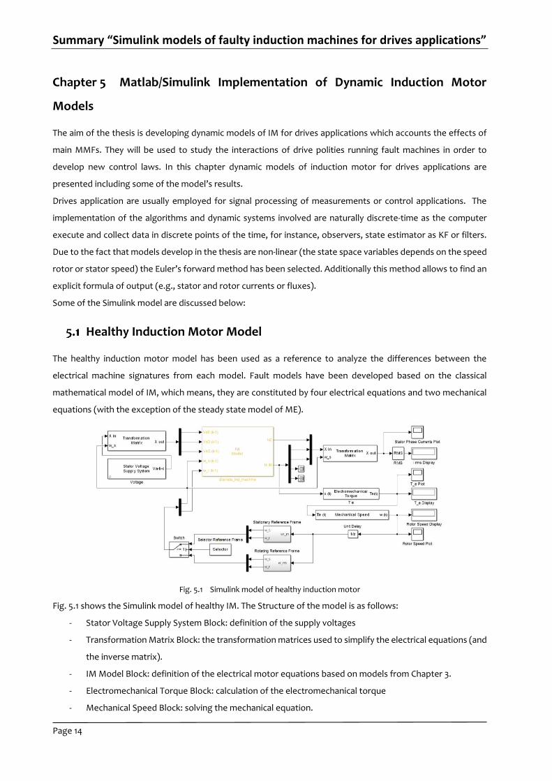
Fig. 5.1 shows the Simulink model of healthy IM. The Structure of the model is as follows:
- Stator Voltage Supply System Block: definition of the supply voltages
- Transformation Matrix Block: the transformation matrices used to simplify the electrical equations (and
the inverse matrix).
- IM Model Block: definition of the electrical motor equations based on models from Chapter 3.
- Electromechanical Torque Block: calculation of the electromechanical torque
- Mechanical Speed Block: solving the mechanical equation.
Summary “Simulink models of faulty induction machines for drives applications”
Page 15
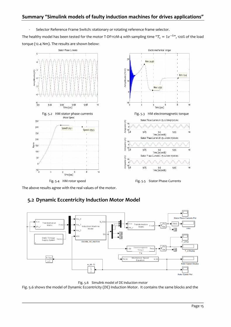
- Selector Reference Frame Switch: stationary or rotating reference frame selector.
The healthy model has been tested for the motor T-DF112M-4 with sampling time “𝑇𝑠 = 1𝑒−5”, 120% of the load
torque (12.4 Nm). The results are shown below:
The above results agree with the real values of the motor.
Dynamic Eccentricity Induction Motor Model
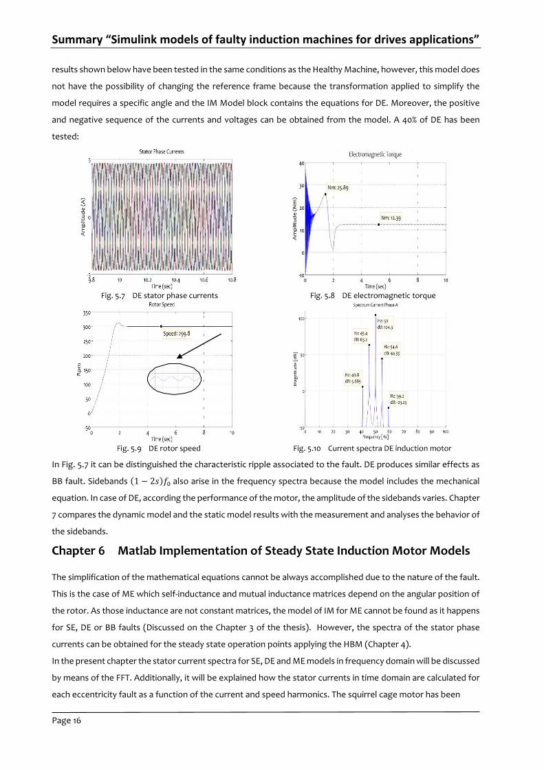
Fig. 5.6 shows the model of Dynamic Eccentricity (DE) Induction Motor. It contains the same blocks and the
Summary “Simulink models of faulty induction machines for drives applications”
Page 16
results shown below have been tested in the same conditions as the Healthy Machine, however, this model does
not have the possibility of changing the reference frame because the transformation applied to simplify the
model requires a specific angle and the IM Model block contains the equations for DE. Moreover, the positive
and negative sequence of the currents and voltages can be obtained from the model. A 40% of DE has been
tested:
In Fig. 5.7 it can be distinguished the characteristic ripple associated to the fault. DE produces similar effects as
BB fault. Sidebands (1 − 2𝑠)𝑓0 also arise in the frequency spectra because the model includes the mechanical
equation. In case of DE, according the performance of the motor, the amplitude of the sidebands varies. Chapter
7 compares the dynamic model and the static model results with the measurement and analyses the behavior of
the sidebands.
Matlab Implementation of Steady State Induction Motor Models
The simplification of the mathematical equations cannot be always accomplished due to the nature of the fault.
This is the case of ME which self-inductance and mutual inductance matrices depend on the angular position of
the rotor. As those inductance are not constant matrices, the model of IM for ME cannot be found as it happens
for SE, DE or BB faults (Discussed on the Chapter 3 of the thesis). However, the spectra of the stator phase
currents can be obtained for the steady state operation points applying the HBM (Chapter 4).
In the present chapter the stator current spectra for SE, DE and ME models in frequency domain will be discussed
by means of the FFT. Additionally, it will be explained how the stator currents in time domain are calculated for
each eccentricity fault as a function of the current and speed harmonics. The squirrel cage motor has been
Summary “Simulink models of faulty induction machines for drives applications”
Page 17
models as a rotor winding induction motor applying the assumption of stator and rotor windings are equal.
For instance, the stator currents in time domain of the DE model are calculated as follows:
The HBM is solved considering only the voltage harmonic with pulsation Ω0,
𝑈𝜂 =𝑈𝑛
2∙ 𝑒𝑗∙(Ω0)∙𝑡 +
𝑈𝑛
2∙ 𝑒𝑗∙(−Ω0)∙𝑡 (6.1)
Only two current harmonics are different than zero:
[
𝐼𝑠𝑐0𝐷𝐸(𝑡)
𝐼𝑠𝑐1𝐷𝐸(𝑡)
𝐼𝑠𝑐2𝐷𝐸(𝑡)
] = [0
𝐼1𝐷𝐸
0] ∙ 𝑒𝑗∙(Ω0)∙𝑡 + [
00
𝐼2𝐷𝐸
] ∙ 𝑒𝑗∙(Ω0−2𝑝Ω𝑚)∙𝑡; (𝑓𝑜𝑟 𝑈𝑛
2∙ 𝑒𝑗∙(Ω0)∙𝑡) ; (6. 2)
Applying the principle of superposition, the current harmonics for the voltage harmonic with pulsation −Ω0are,
[
𝐼𝑠𝑐0𝐷𝐸(𝑡)
𝐼𝑠𝑐1𝐷𝐸(𝑡)
𝐼𝑠𝑐2𝐷𝐸(𝑡)
] = [
00
𝐼1𝐷𝐸
] ∙ 𝑒𝑗∙(−Ω0)∙𝑡 + [(0
𝐼2𝐷𝐸
0
) ∙] 𝑒−𝑗∙(Ω0−2𝑝Ω𝑚)∙𝑡; (𝑓𝑜𝑟 𝑈𝑛
2∙ 𝑒𝑗∙(−Ω0)∙𝑡) ; (6. 3)
The backward and forward symmetrical component can be found as:
[
𝐼𝑠𝑐0𝐷𝐸(𝑡)
𝐼𝑠𝑐1𝐷𝐸(𝑡)
𝐼𝑠𝑐2𝐷𝐸(𝑡)
] = [
0𝐼1𝐷𝐸 ∙ 𝑒𝑗∙(Ω0)∙𝑡
𝐼1𝐷𝐸 ∙ 𝑒𝑗∙(−Ω0)∙𝑡
] + [
0
𝐼2𝐷𝐸 ∙ 𝑒−𝑗∙(Ω0−2𝑝Ω𝑚)∙𝑡
𝐼2𝐷𝐸 ∙ 𝑒𝑗∙(Ω0−2𝑝Ω𝑚)∙𝑡
] ; 𝑓𝑜𝑟 (𝑈𝜂 , 𝜂 = ±1); (6. 4)
From equation 6.4 it can be proved that backward symmetrical component is equal to the conjugate forward
symmetrical component:
𝐼𝑠𝑐2𝐷𝐸 = 𝐼𝑠𝑐1
𝐷𝐸 (6.5)
Finally, the time domain stator currents are obtained applying the inverse SC transformation matrix:
[
𝐼𝑎𝐷𝐸(𝑡)
𝐼𝑏𝐷𝐸(𝑡)
𝐼𝑐𝐷𝐸(𝑡)
] =1
√3∙ [
1 1 11 𝑎2 𝑎1 𝑎 𝑎2
] ∙ [
𝐼𝑠𝑐0𝐷𝐸(𝑡)
𝐼𝑠𝑐1𝐷𝐸(𝑡)
𝐼𝑠𝑐2𝐷𝐸(𝑡)
] (6. 6)
This chapter includes simulations of the motor model “T-DF112M-4” with different levels of eccentricity for all
eccentricity types. In order to present the content, this summary shows only one of the models discussed:
1. DE static model tested with 40% of eccentricity
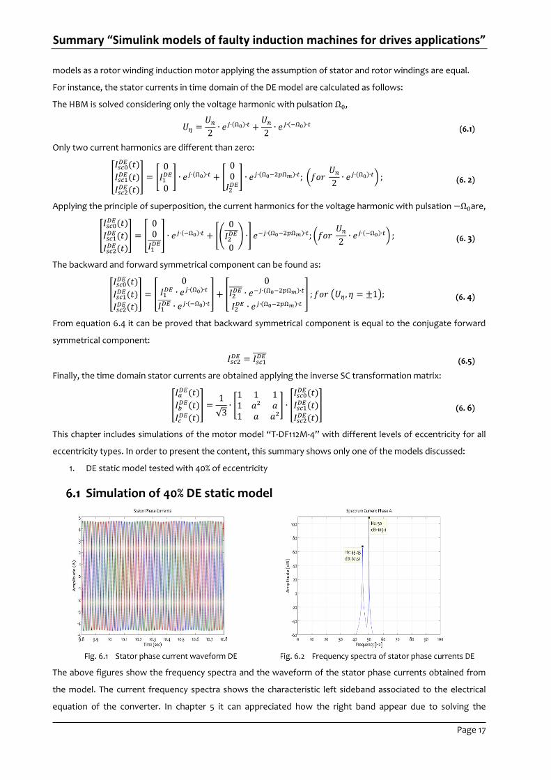
Simulation of 40% DE static model
The above figures show the frequency spectra and the waveform of the stator phase currents obtained from
the model. The current frequency spectra shows the characteristic left sideband associated to the electrical
equation of the converter. In chapter 5 it can appreciated how the right band appear due to solving the
Summary “Simulink models of faulty induction machines for drives applications”
Page 18
mechanical equation. Furthermore, it can also be seen the ripple on the stator phase currents characteristic of
this type of faults. As it was mentioned, the simulation results are discussed based on the measurement results
on chapter 7.
Validation of Model Results by Experimental Test
In the previous chapter, the dynamic and static models for DE were presented and the simulation results were
showed. The simulation results agree with the expected values of the real machine when it is affected by those
faults, for instance, the additional frequencies on the stator phase currents. However, the final validation is done
by studying the evolution of the sidebands when the motor is working under different conditions.
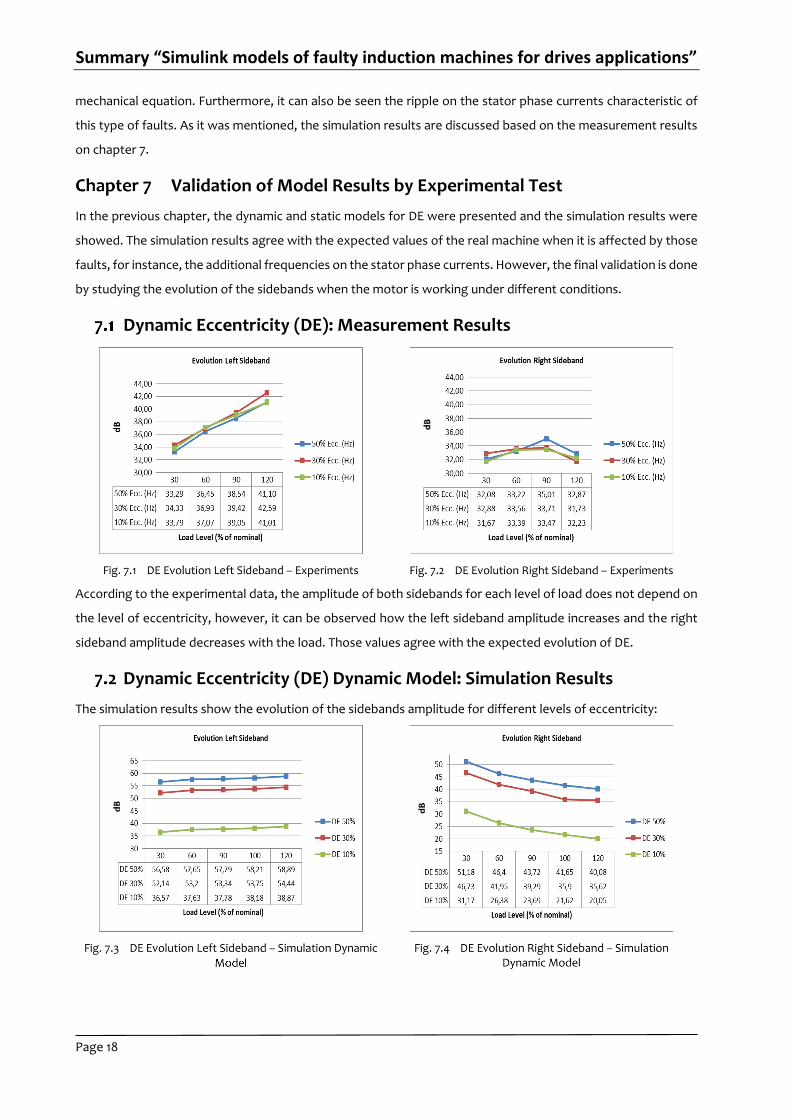
Dynamic Eccentricity (DE): Measurement Results
According to the experimental data, the amplitude of both sidebands for each level of load does not depend on
the level of eccentricity, however, it can be observed how the left sideband amplitude increases and the right
sideband amplitude decreases with the load. Those values agree with the expected evolution of DE.
Dynamic Eccentricity (DE) Dynamic Model: Simulation Results
The simulation results show the evolution of the sidebands amplitude for different levels of eccentricity:
Summary “Simulink models of faulty induction machines for drives applications”
Page 19
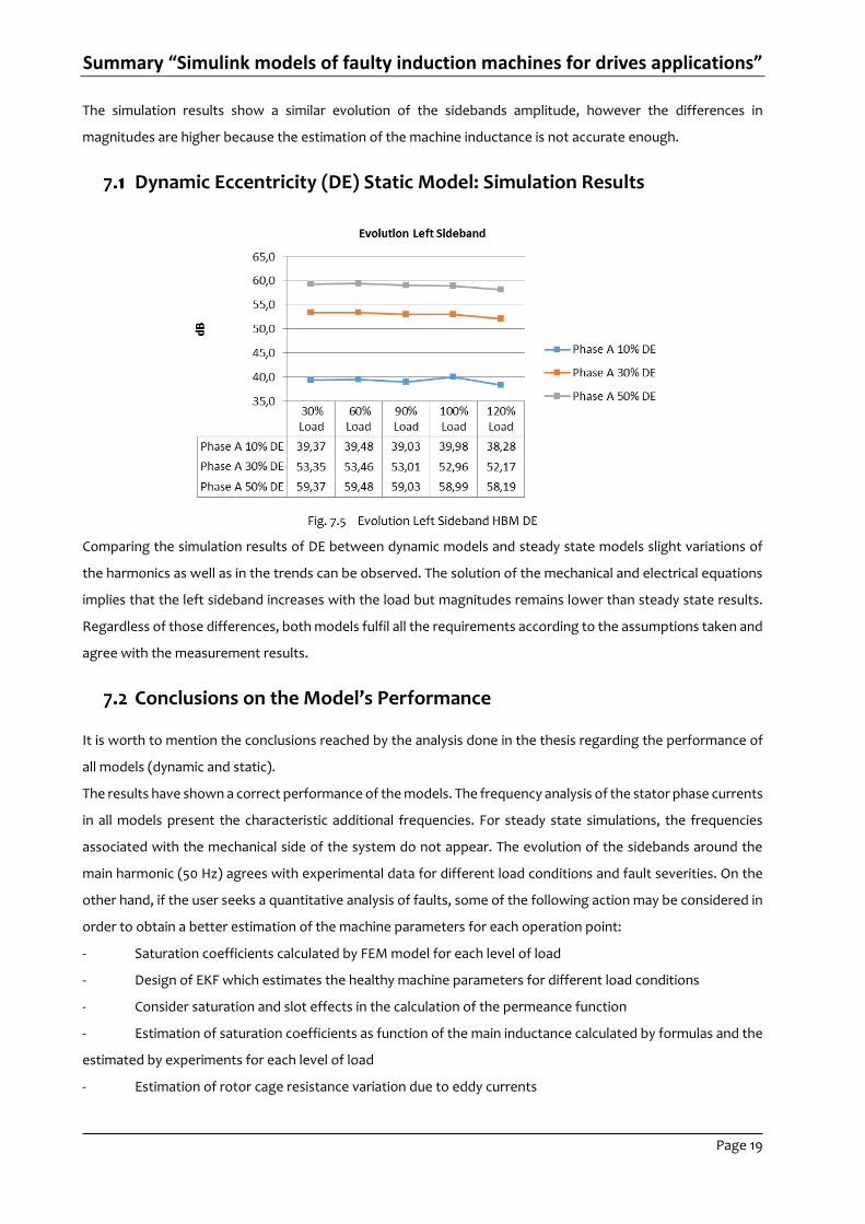
The simulation results show a similar evolution of the sidebands amplitude, however the differences in
magnitudes are higher because the estimation of the machine inductance is not accurate enough.
Dynamic Eccentricity (DE) Static Model: Simulation Results
Comparing the simulation results of DE between dynamic models and steady state models slight variations of
the harmonics as well as in the trends can be observed. The solution of the mechanical and electrical equations
implies that the left sideband increases with the load but magnitudes remains lower than steady state results.
Regardless of those differences, both models fulfil all the requirements according to the assumptions taken and
agree with the measurement results.
Conclusions on the Model’s Performance
It is worth to mention the conclusions reached by the analysis done in the thesis regarding the performance of
all models (dynamic and static).
The results have shown a correct performance of the models. The frequency analysis of the stator phase currents
in all models present the characteristic additional frequencies. For steady state simulations, the frequencies
associated with the mechanical side of the system do not appear. The evolution of the sidebands around the
main harmonic (50 Hz) agrees with experimental data for different load conditions and fault severities. On the
other hand, if the user seeks a quantitative analysis of faults, some of the following action may be considered in
order to obtain a better estimation of the machine parameters for each operation point:
- Saturation coefficients calculated by FEM model for each level of load
- Design of EKF which estimates the healthy machine parameters for different load conditions
- Consider saturation and slot effects in the calculation of the permeance function
- Estimation of saturation coefficients as function of the main inductance calculated by formulas and the
estimated by experiments for each level of load
- Estimation of rotor cage resistance variation due to eddy currents
Summary “Simulink models of faulty induction machines for drives applications”
Page 20
In conclusion, the dynamic and steady models presented in the thesis demonstrate that a qualitative analysis of
faults can be carried out by only considering MMFs effects fulfilling all requirements needed for drives
applications as the tendencies shown in simulations match the experimental data.
Drives Applications with Faulty Induction Motor models: Hardware
in the Loop Simulations HIL
In the past the construction of prototypes was a common practice during the test phase of new ideas/concepts
and products. This testing stage required long periods of time and the investment of many resources. Another
important factor was the safety during the tests as the operators could suffer accidents. In the past few decades,
the evolution of the computers and the development of new platforms for modelling implementation have
helped to reduce the time invested to transform an idea into a product, the total cost of the whole process and
have improved the work conditions decreasing the risk of prospective accidents.
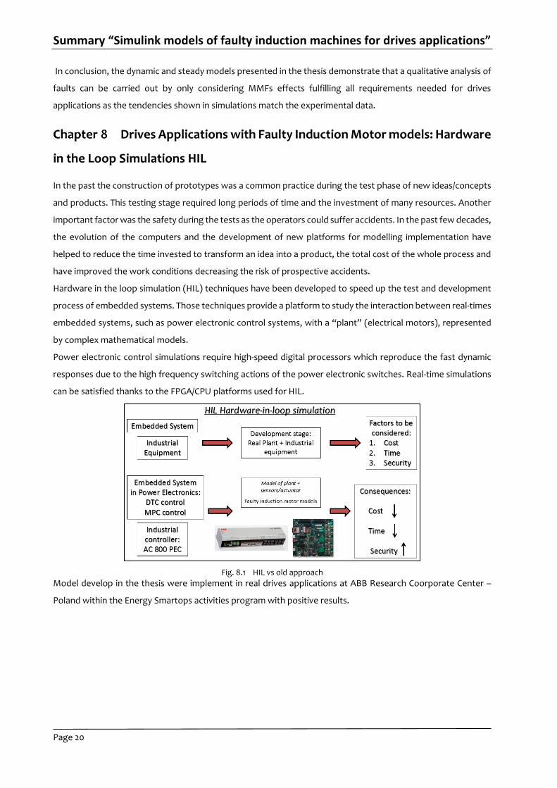
Hardware in the loop simulation (HIL) techniques have been developed to speed up the test and development
process of embedded systems. Those techniques provide a platform to study the interaction between real-times
embedded systems, such as power electronic control systems, with a “plant” (electrical motors), represented
by complex mathematical models.
Power electronic control simulations require high-speed digital processors which reproduce the fast dynamic
responses due to the high frequency switching actions of the power electronic switches. Real-time simulations
can be satisfied thanks to the FPGA/CPU platforms used for HIL.
Model develop in the thesis were implement in real drives applications at ABB Research Coorporate Center –
Poland within the Energy Smartops activities program with positive results.

Summary “Simulink models of faulty induction machines for drives applications”
Page 21
Implementation of Healthy Induction Motor model into Zynq-7000 All
Programmable SoC - Discussion of Results
Following figures show supply voltages, electromagnetic torque and rotor speed signals calculated by ZYNQ
during the execution of the Healthy machine model (Fig. 8.4 / Fig. 8.5) and BB model (Fig. 8.6 / Fig. 8.7) running
at the same operation point, using the stationary reference frame and expressed in d-q components. The
magnitude and behaviour of the machine signatures were equal to the simulation results obtained in Simulink
after applying the proper scale factors.
Analysis and Diagnosis of Electrical and Mechanical Faults in
Induction Motors
The content of this chapter summarizes some of the work carried out in the field of fault diagnosis of IMs through
simulation and experimental data.
9.1 Evaluation of the Asymmetry Factor for BB Simulations Changes of simulation: symmetry and asymmetry
coefficient are used to model BB faults. Some of the assumptions taken in modelling are review as well
as the evolution of their values for different faults.
Summary “Simulink models of faulty induction machines for drives applications”
Page 22
9.2 Diagnosis of Static Eccentricity vs Unbalance Supply Voltages: difficulties in diagnosis of both faults are
pointed out. Furthermore, a method to find differences is suggested.
9.3 Modelling DE and Cage asymmetry: the possibilities offer by combining BB and DE models for fault
diagnosis purposes are investigated supported by experimental data.
9.4 Comparison of Mechanical and Broken Bar Faults by means of Positive and Negative Frequency Spectrum
of the Stator Phase Current in IM: an alternative algorithm of Fourier transform has been applied in order
to find differences between faults in the frequency spectra of the stator currents.
9.5 Interactions between Electrical and mechanical faults by means of MCSA: study based on the evolution of
the (1 − 2𝑠)𝑓0 sidebands when an induction motor with BB is also affected by a mechanical fault with
similar frequency range.
For example:
9.3 Modelling DE and Cage asymmetry
DE and BB faults are difficult to distinguish due to the fact that same sidebands around the main harmonic
appear. In both cases the evolution of the sideband’s magnitudes is similar, for instance, regarding changes in
the load. With the aim to bringing light to this challenge, mathematical models based on main MMFs may be
used to study new algorithm of fault diagnosis. Three models have been tested: Model of BB, model of DE and
a third one that combines the faults. The results obtained from all models in comparison with the experimental
data reveals similar trends proving the suitability of the model for diagnosis purposes.
- Experimental Results
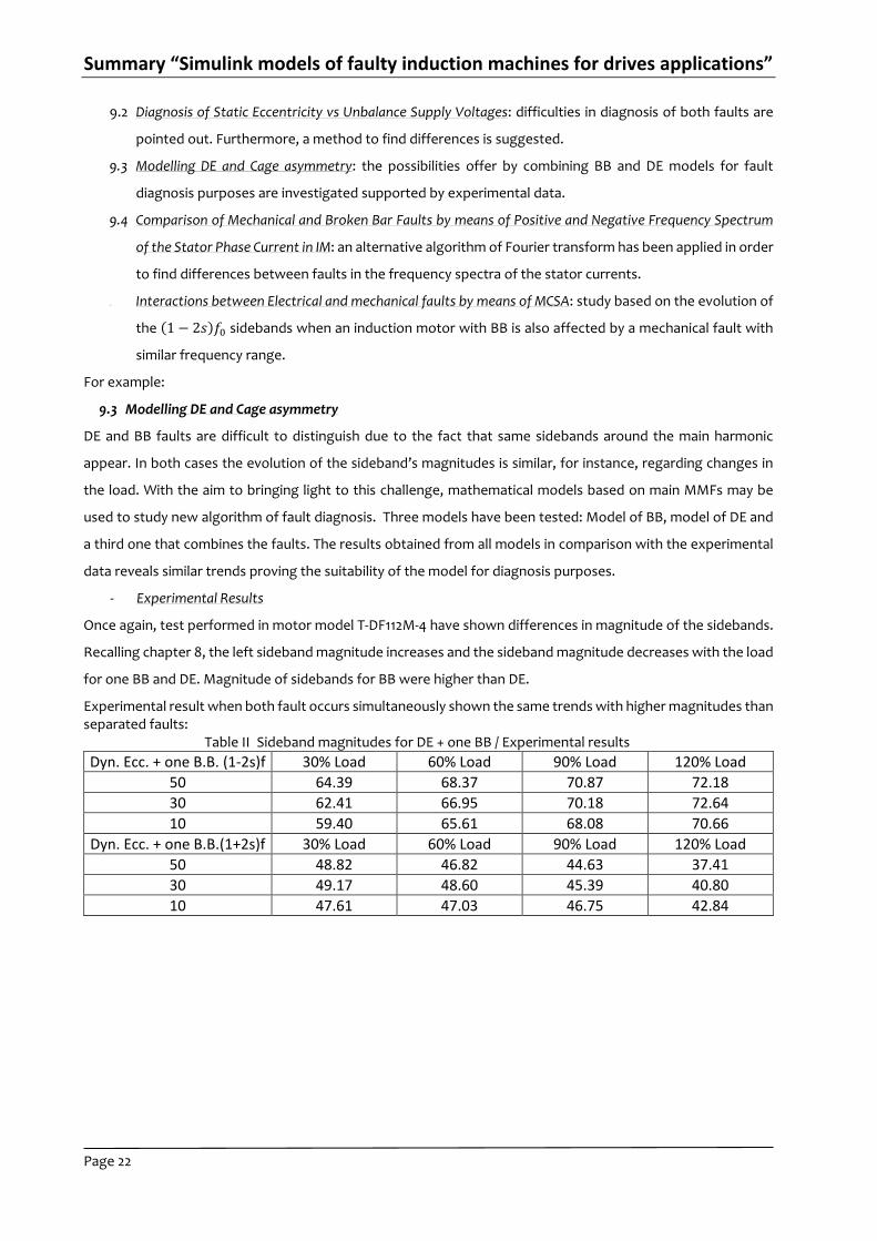
Once again, test performed in motor model T-DF112M-4 have shown differences in magnitude of the sidebands.
Recalling chapter 8, the left sideband magnitude increases and the sideband magnitude decreases with the load
for one BB and DE. Magnitude of sidebands for BB were higher than DE.
Experimental result when both fault occurs simultaneously shown the same trends with higher magnitudes than separated faults:
Table II Sideband magnitudes for DE + one BB / Experimental results
Dyn. Ecc. + one B.B. (1-2s)f 30% Load 60% Load 90% Load 120% Load
50 64.39 68.37 70.87 72.18
30 62.41 66.95 70.18 72.64
10 59.40 65.61 68.08 70.66
Dyn. Ecc. + one B.B.(1+2s)f 30% Load 60% Load 90% Load 120% Load
50 48.82 46.82 44.63 37.41
30 49.17 48.60 45.39 40.80
10 47.61 47.03 46.75 42.84

Summary “Simulink models of faulty induction machines for drives applications”
Page 23
Regarding simulation results, it can be proven the same trends in the sidebands as well as the magnitudes values.
Sorting from highest to lowest: DE + one BB / one BB / DE.
Table III Sideband magnitudes for DE + one BB / Simulation results
Dyn. Ecc. + one B.B. - (1-2s)f 30% Load 60% Load 90% Load 100% Load 120% Load
50 58.96 64.37 65.67 67.86 68.55
45 56.91 63.38 64.96 67.28 68.1
40 55.01 62.58 64.35 66.67 67.68
Dyn. Ecc. + one B.B. - (1+2s)f 30% Load 60% Load 90% Load 100% Load 120% Load
50 53.17 52.61 51.08 50.78 47.96
45 51.11 51.63 50.37 50.2 47.44
40 49.2 50.83 49.77 49.69 48.34
It is true that differences between DE + one BB and BB fault are not big enough as it was shown in experimental
results, but it is also true that parameters for estimation of BB may be not fully correct. In the light of results
presented, it can be concluded that mono harmonic models accounting simultaneously BB and DE faults may be
use for diagnosis purposes.
Conclusions
The main contribution of the thesis has been the development of a library in Simulink of dynamic induction motor
models under electrical and mechanical faults for drives applications. These model have been based on the
Summary “Simulink models of faulty induction machines for drives applications”
Page 24
winding function approach for mathematical modelling of IMs accounting only effects of the main MMFs.
Furthermore, steady state models accounting eccentricities faults have been created in Matlab following the
HBM. The main advantage of the methodology presented is that it allows developing models of different types
of electrical machines or considering effects of multi-harmonics. In addition, effects of saturation or slotting can
be taken into account by adding additional terms to the permeance function. The research seeks a qualitative
analysis of the electrical and mechanical faults by means of MCSA applied to the stator phase currents.
Simulation results shown in the thesis have mainly been focused in the analysis of the frequency spectra of the
stator phase currents with the objective of studying the evolution of the characteristic frequencies for each type
of fault. Performance of the models has been supported by experimental data. It has been necessary to design
a DAQ system for data collecting and the estimation of the machine parameters. A simple user graphic interface
for estimation of machine parameter has also been designed. Experimental results have validated the trend
shown in Simulation results regarding evolution of the frequencies associated to faults and magnitudes of
machine signatures such as amplitude of currents, torque and speed for different operation points of the motor.
However, it has been observed a strong dependence between the magnitude of these frequencies and the
machine signatures with the parameters.
Fault diagnosis of induction motors has been another of the objectives. The work carried out in this field has
been published in international conferences and journals. Despite the fact that models only account main MMFs,
results proved the suitability of them for this purpose.
Summarizing, models presented allow the user to carry out a qualitative analysis of electrical and mechanical
faults on IMs based on main MMFs offering an accurate representation of the main fault effects over the currents
suitable for drives applications.
R e f e r e n c e s - s e l e c t e d p o s i t i o n s
[1]. G.B. Kliman, J. Stein, R.D. Endicott, R.A. Koegl, “Noninvasive Detection of Broken Rotor Bars in
Operating Induction Motor”, Energy Conversion, IEEE Transactions on, vol. 3, no 4, pp. 873-879, 1988.
[2]. T. J. Sobczyk, P. Drozdowski, “Inductances of electrical machine winding with a non-uniform air-gap”,
Archiv fur Elektrotechnik, vol. 76, pp. 213-218, 1993.
[3]. T. J. Sobczyk, P. Vas, C. Tassoni, “Models for Induction motors with air-gap asymmetry for diagnosis
purposes”, ICEM Proceedings International Conference on Electrical Machines, vol. II, pp. 79-78, 1996.
[4]. T. J. Sobczyk, K. Weinreb, T. Wegiel, M. Sulowicz, “Theoretical study of effects due to rotor eccentricities
in induction motors", In IEEE International Symposium on Diagnostics for Electrical Machines, Power
Electronics and Drives (SDEMPED’99), pp.289 -295, 1999.
[5]. T.J. Sobczyk, W. Maciołek, “Effects due to higher space harmonics in induction motor with faulty cage”,
Archives of Electrical Engineering, PWN, Warsaw, vol. 51, pp. 203-215, 2002.
[6]. S. Nandi, R.M. Bharadwaj, H.A. Toliyat, “Mixed eccentricity in three phase induction machines: analysis,
simulation and experiments”, Industry Applications Conference, 2002. 37th IAS Annual Meeting.
Conference Record of the, vol.3, pp. 1525-1532, 2002.
[7]. B. Ozpineci, L. M. Tolbert, “Simulink implementation of induction machine model - a modular approach”,
IEMDC 2003 In Electric Machines and Drives Conference, vol. 2, pp. 728-734, 2003.
Summary “Simulink models of faulty induction machines for drives applications”
Page 25
[8]. J. Faiz, I. T. Ardekanei, H. A. Toliyat, “An evaluation of inductances of a squirrel-cage induction motor
under mixed eccentric conditions”, Energy Conversion, IEEE Transactions on , vol. 18, no. 2, pp. 252-258,
2003.
[9]. T.J. Sobczyk, W. Maciołek, “Does the component (1-2s)fo in stator currents is sufficient for detection of
rotor cage faults?”, Proc. 5th IEEE Symp. on Diagnostics of Electric Machines, Power Electronics and
Drives, (SDEMPED 2005), pp. 175-179, 2005.
[10]. A. Siddique, G.S. Yadava, B. Singh, “A review of stator fault monitoring techniques of induction motors”,
Energy conversion, IEEE transactions on, vol. 20, no. 1, pp. 106-114, 2005.
[11]. G. M. Joksimović, “Dynamic simulation of cage induction machine with air gap eccentricity”, IEE
Proceedings-Electric Power Applications, vol. 152, no. 4, pp. 803-811, 2005.
[12]. A. Bellini, C. Concari, G. Franceschini, E. Lorenzani, C. Tassoni, A. Toscani, “Thorough understanding and
experimental validation of current sideband components in induction machines rotor monitoring”, IEEE
Industrial Electronics, IECON 2006 - 32nd Annual Conference on, pp. 4957-4962, 2006.
[13]. A. A. Ansari, D. M. Deshpande, “Mathematical Model of Asynchronous Machine in MATLAB Simulink”,
International Journal of Engineering Science and Technology, vol. 2, no. 5, pp. 1260-1267, 2010.
[14]. A. Aktaibi, D. Ghanim, “Dynamic simulation of a three phase induction motor using Matlab Simulink”,
2011.
[15]. C. Kreischer, L. Golebiowski, “Comparison of different methods to determine defects in the stator core”,
Electrical Machines (ICEM), 2012 XXth International Conference on, pp. 1608-1611, 2012.
[16]. J. Martinez, A Belahcen, A. Arkkio, “Broken bar indicators for cage induction motors and their
relationship with the number of consecutive broken bars”, IET Electric Power Applications, vol. 7, no. 8,
pp. 633-642, 2013.
[17]. W. L. Leedy, “Simulink/MATLAB Dynamic Induction Motor Model for Use as A Teaching and Research
Tool”, International Journal of Soft Computing and Engineering (IJSCE), vol. 3, no. 4, pp. 102-107, 2013.
[18]. K. Weinreb, “Diagnostics of an induction-motor rotor by the spectral analysis of stator currents”,
Thermal Engineering, vol. 60, no. 14, pp. 1006-1023, 2013.
[19]. J. Anju, V. Jose, D. Sebastian, “Stator fault detection in induction motor under unbalanced supply
voltage”, Emerging Research Areas: Magnetics, Machines and Drives (AICERA/iCMMD), 2014 Annual
International Conference on, pp. 1-6, 2014.
B o o k s
[1]. G. M. Fitchtenholz, “Differential and integral calculus”, tom. 3, Warsaw: PWN (in Polish), 1980.
[2]. P. Vas, “Sensorless Vector and Direct Torque Control”, Oxford: Oxford Science Publications, 1998.
[3]. J. Fraile Mora, “Electrical Machines”, edn.VI. Madrid: McGraw-Hill, 2003.
[4]. T.J. Sobczyk, “Methodological aspects of mathematical modelling of induction machines” (in Polish),
WNT, Warsaw, 2004.
[5]. I. Boldea, “The induction machines design handbook”, CRC press, 2009.
[6]. A. D. Poularikas, “Handbook of formulas and tables for signal processing”, CRC Press, 2010.

Summary “Simulink models of faulty induction machines for drives applications”
Page 26
[7]. P. Waide, C. U. Brunner “Energy-Efficiency Policy Opportunities for Electric Motor-Driven Systems”, IEA
- International Energy Agency, Energy Efficiency Series, 2011.
[8]. Krause, Paul C, Wasynczuk O., Sudhoff S. D, Pekarek S., “Analysis of electric machinery and drive
systems”, John Wiley & Sons, 2013.
P u b l i c a t i o n s i s s u e d b y t h e a u t h o r i n c o n f e r e n c e s
[1]. A.J. Fernandez Gomez, T.J. Sobczyk, “Comparison of Fourier spectra of induction machine for cage
asymmetry and faults in mechanical part of a drive”, CM 2013 and MFPT 2013, 2013.
[2]. A. J. Fernandez Gomez, T. J. Sobczyk, “Motor current signature analysis apply for external mechanical
fault and cage asymmetry in induction motors”, Diagnostics for Electric Machines, Power Electronics
and Drives (SDEMPED), 2013 9th IEEE International Symposium on, pp. 136-141, 2013, (IEEE Xplore Digital
Library) .
[3]. A. J. Fernandez Gomez, A. Dziechciarz, T.J. Sobczyk, “Mathematical modeling of eccentricities in
induction machines by the mono-harmonic model”, Diagnostics for Electric Machines, Power Electronics
and Drives (SDEMPED), 2013 9th IEEE International Symposium on, pp. 317-322, 2013, (IEEE Xplore Digital
Library).
[4]. A. J. Fernandez Gomez, “Simulink models of faulty induction machines for drivers applications”,
International PhD Workshop OWD13, conference archives PTETiS, vol. 33, pp. 204-209, 2013.
[5]. A. J. Fernandez Gomez, Victor H. Jaramillo, James R. Ottewill, “Fault detection in electric motors by
means of the extended Kalman Filter as disturbance estimator”, Control (CONTROL), 2014 UKACC
International Conference on, pp. 432 - 437, 2014, (IEEE Xplore Digital Library).
[6]. A. J. Fernandez Gomez, T.J. Sobczyk, K. Weinreb, “Influence on Rotor Broken Bar Faults Diagnosis of
Mechanical Torque Pulsations by Means of FFT”, Diagnostics for Electric Machines, Power Electronics
and Drives (SDEMPED), 2015 10th IEEE International Symposium on (Submitted), 2015.
P u b l i c a t i o n s i s s u e d b y t h e a u t h o r i n J o u r n a l s
[1]. A.J. Fernandez Gomez, T.J. Sobczyk, “Influence of design data of induction motor on effects of cage
asymmetry”, Prace Naukowe Instytutu Maszyn, Napedów I Pomiarów Elektrycznych Politechniki
Wroclawskiej, Vol. I, pp 357-364, 2012.
[2]. A. J. Fernandez Gomez, T.J. Sobczyk, “Influence of Induction Motor Design Data on Effects of Cage
Asymmetry”, Journal of Energy and Power Engineering, vol. 7, no. 8, pp 1586-1591, 2013.
[3]. A. J. Fernandez Gomez, M. Sułowicz, T.J. Sobczyk, “Induction motor signatures analysis under influence
of mechanical and electrical fault”, Instytut Napedów I Maszyn Elektrycznuch KOMEL, vol. 104, pp 293-
300, 2014.
[4]. A. J. Fernandez Gomez, M. Sułowicz, T.J. Sobczyk, “Influence of mechanical faults on induction
machines with electrical faults”, Czasopismo Techniczne Elektrotechnika, 2015.