apex target system
TRANSCRIPT
APEXTarget System
Philip Schuster (co-spokesperson)Perimeter Institute
on behalf of the APEX Collaboration
1Tuesday, September 21, 2010
Outline
• Physics considerations on the APEX target
• Target design
• Performance studies
• Alignment and Optics Calibration
• Outlook
2Tuesday, September 21, 2010
Physics Considerations
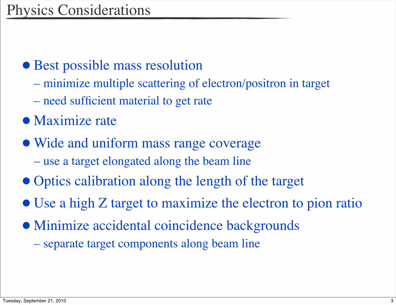
• Best possible mass resolution– minimize multiple scattering of electron/positron in target– need sufficient material to get rate
• Maximize rate
• Wide and uniform mass range coverage– use a target elongated along the beam line
• Optics calibration along the length of the target
• Use a high Z target to maximize the electron to pion ratio
• Minimize accidental coincidence backgrounds– separate target components along beam line
3Tuesday, September 21, 2010
Design Considerations
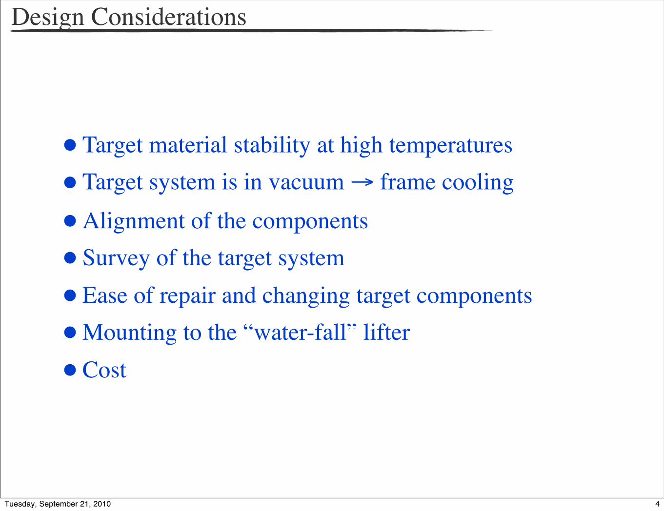
• Target material stability at high temperatures
• Target system is in vacuum → frame cooling
• Alignment of the components
• Survey of the target system
• Ease of repair and changing target components
• Mounting to the “water-fall” lifter
• Cost
4Tuesday, September 21, 2010

Target Design
Designed and built largely by the SLAC group for 2-
pass APEX test run conditions5Tuesday, September 21, 2010
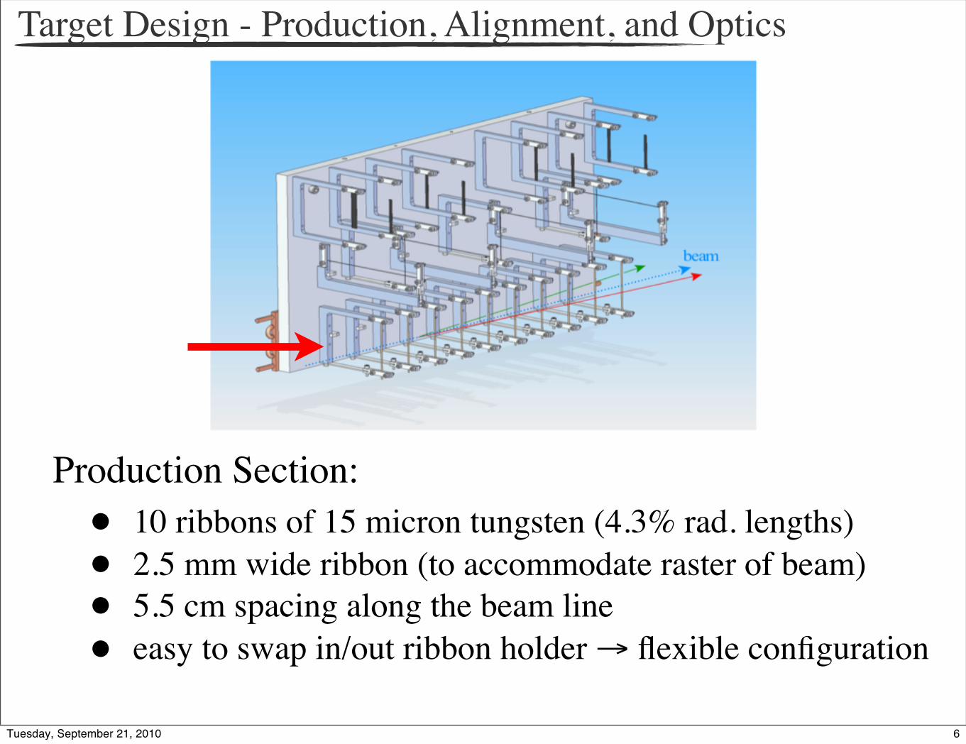
Target Design - Production, Alignment, and Optics
Production Section:• 10 ribbons of 15 micron tungsten (4.3% rad. lengths)• 2.5 mm wide ribbon (to accommodate raster of beam)• 5.5 cm spacing along the beam line• easy to swap in/out ribbon holder → flexible configuration
6Tuesday, September 21, 2010
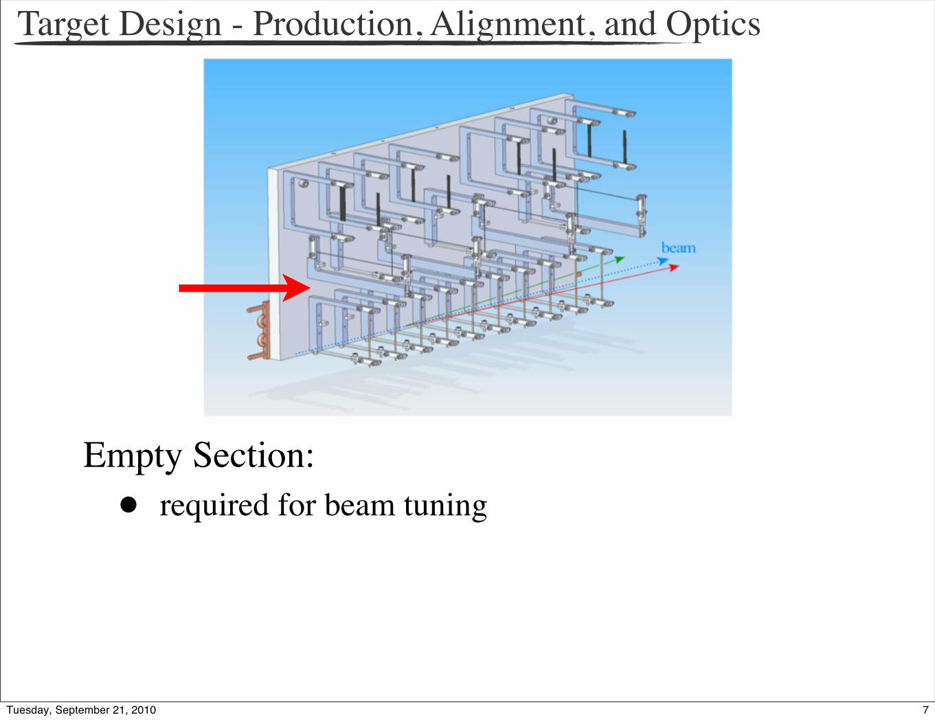
Target Design - Production, Alignment, and Optics
Empty Section:• required for beam tuning
7Tuesday, September 21, 2010
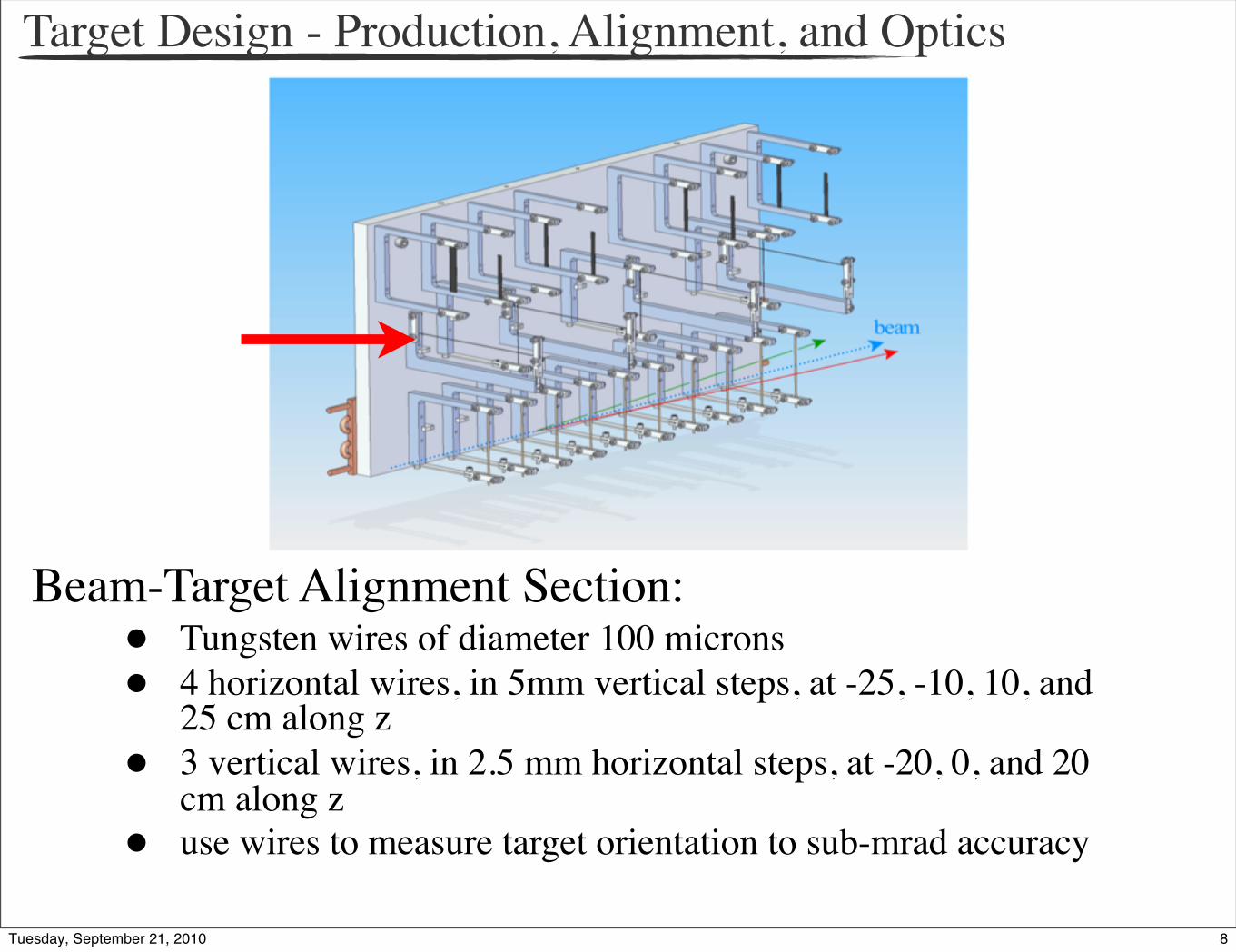
Beam-Target Alignment Section:• Tungsten wires of diameter 100 microns• 4 horizontal wires, in 5mm vertical steps, at -25, -10, 10, and
25 cm along z• 3 vertical wires, in 2.5 mm horizontal steps, at -20, 0, and 20
cm along z• use wires to measure target orientation to sub-mrad accuracy
Target Design - Production, Alignment, and Optics
8Tuesday, September 21, 2010
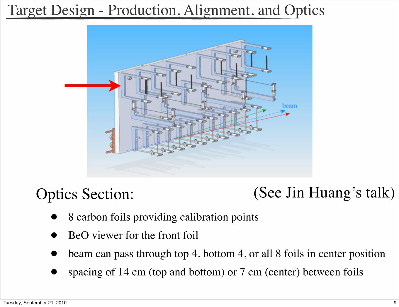
Target Design - Production, Alignment, and Optics
Optics Section:• 8 carbon foils providing calibration points
• BeO viewer for the front foil
• beam can pass through top 4, bottom 4, or all 8 foils in center position
• spacing of 14 cm (top and bottom) or 7 cm (center) between foils
(See Jin Huang’s talk)
9Tuesday, September 21, 2010
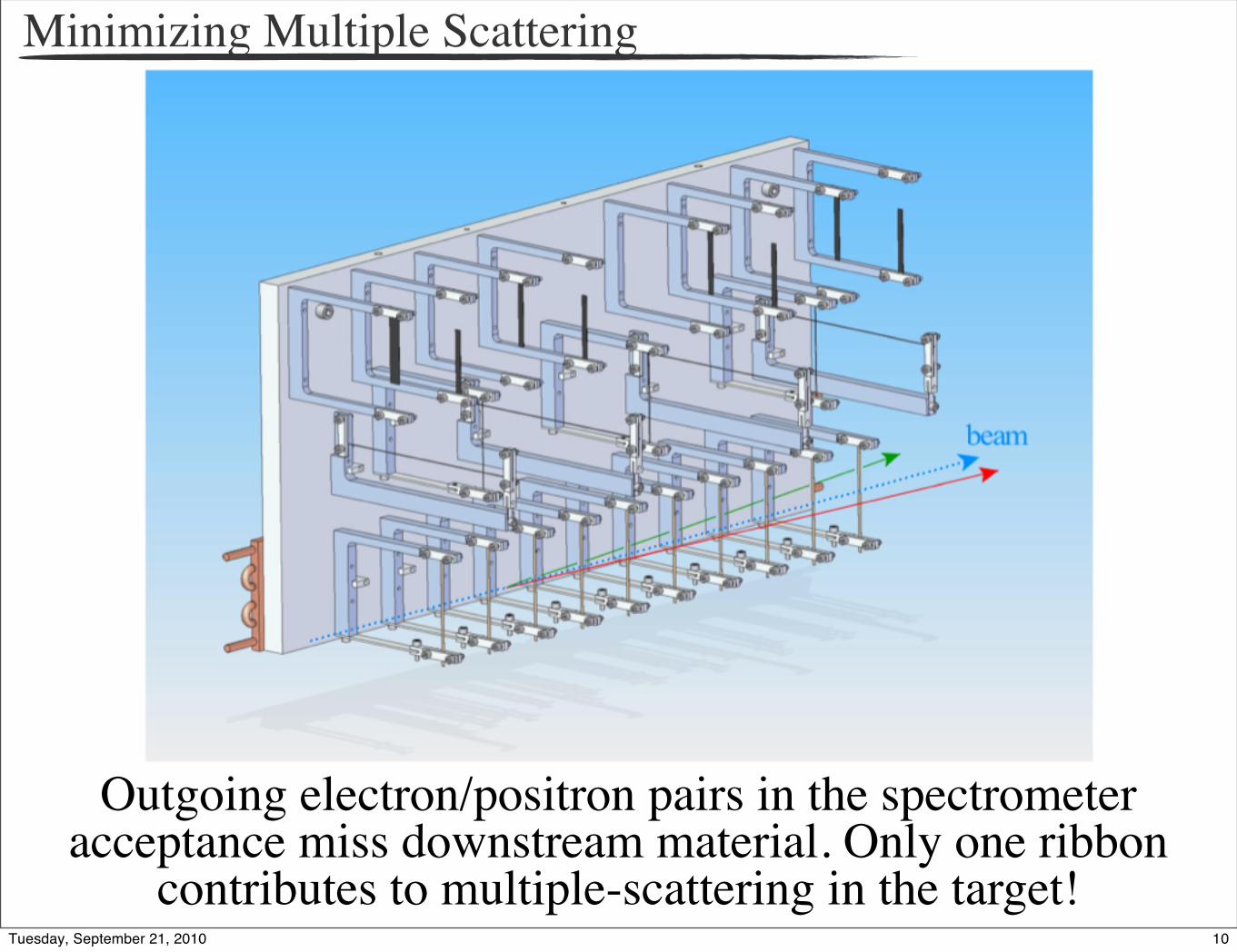
Minimizing Multiple Scattering
Outgoing electron/positron pairs in the spectrometer acceptance miss downstream material. Only one ribbon
contributes to multiple-scattering in the target!10Tuesday, September 21, 2010

Extended Mass Range Coverage
• 11 degree (horizontal) maximum angular clearance
• Variation of 1 degree over the extent of the target
• 50% increase in mass coverage per setting
11Tuesday, September 21, 2010
Reducing Accidental Coincidence Backgrounds
• See Jin Huang’s talk on optics calibration and optics from the E06010 experiment for illustration
• Transverse position resolution of 1 mm expected → 1 cm resolution along the beam line
• By requiring electron/positron pair to come from the same vertex, we can reduce accidental backgrounds
• Even with 5 cm resolution, we obtain a factor of 4 rejection (assumed in proposal), but we expect to do better.
12Tuesday, September 21, 2010
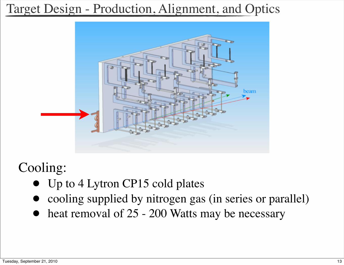
Target Design - Production, Alignment, and Optics
Cooling:• Up to 4 Lytron CP15 cold plates• cooling supplied by nitrogen gas (in series or parallel)• heat removal of 25 - 200 Watts may be necessary
13Tuesday, September 21, 2010

Target Design - Production, Alignment, and Optics
Cooling:• Up to 4 Lytron CP15 cold plates• cooling supplied by nitrogen gas (in series or parallel)• heat removal of 25 - 200 Watts may be necessary
13Tuesday, September 21, 2010

Target Design - Tensioned Holders
3 24
A
3 2 14
REV DESCRIPTION DWN CHKRAPVD DATE
D D
C C
C
B
OF
SH
APPROVALSDEC
TOLERANCES:
FRACTIONS
.XX
DIMENSIONS ARE IN
.XXX
.XXXX
BREAK EDGES .005-.015
INCHES.
INTERNAL CORNERS R.015 MAX
ALL SURF
ENGR
DWN
CHKR
DATE
UNLESS OTHERWISE SPECIFIED
ASME Y14.5M-1994 AND Y14.41-2003DIMENSIONING AND TOLERANCING IS IAW
NEXT ASSEMBLIES:
SCALE:
C
CAD FILE NAME:
±
±±±
DRAWING NUMBER REVISION NUMBER
ANGLE ±
DO NOT SCALE DRAWING
THE DRAWINGS, SPECIFICATIONS AND OTHER DATA HEREIN PROVIDED SHALLNOT BE COPIED, PUBLISHED OR OTHERWISE FURTHER DISSEMINATED WITHOUT
PRIOR WRITTEN PERMISSION OF STANFORD UNIVERSITY/SLAC
SLAC FORMAT V3.0
!"
#"$
#%
3 24
A
3 2 14
REV DESCRIPTION DWN CHKRAPVD DATE
D D
C C
C
B
OF
SH
APPROVALSDEC
TOLERANCES:
FRACTIONS
.XX
DIMENSIONS ARE IN
.XXX
.XXXX
BREAK EDGES .005-.015
INCHES.
INTERNAL CORNERS R.015 MAX
ALL SURF
ENGR
DWN
CHKR
DATE
UNLESS OTHERWISE SPECIFIED
ASME Y14.5M-1994 AND Y14.41-2003DIMENSIONING AND TOLERANCING IS IAW
NEXT ASSEMBLIES:
SCALE:
C
CAD FILE NAME:
±
±±±
DRAWING NUMBER REVISION NUMBER
ANGLE ±
DO NOT SCALE DRAWING
THE DRAWINGS, SPECIFICATIONS AND OTHER DATA HEREIN PROVIDED SHALLNOT BE COPIED, PUBLISHED OR OTHERWISE FURTHER DISSEMINATED WITHOUT
PRIOR WRITTEN PERMISSION OF STANFORD UNIVERSITY/SLAC
SLAC FORMAT V3.0
!"#
"$
Tensioning beam keeps ribbons/wires straight as
temperatures increase
14Tuesday, September 21, 2010

Performance Studies - Production Target
• heating of production ribbons is not overly severe
• elongation of hot ribbons is much smaller than range of tensioning beam
• horizontal temperature profile on ribbons is uniform so that transverse stresses are not severe
from Clive Field
15Tuesday, September 21, 2010
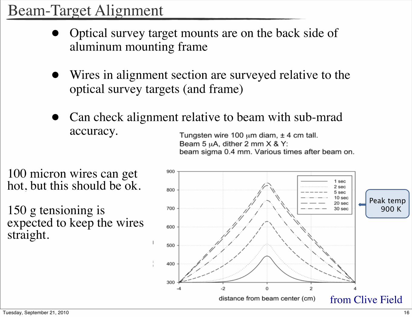
Beam-Target Alignment• Optical survey target mounts are on the back side of
aluminum mounting frame
• Wires in alignment section are surveyed relative to the optical survey targets (and frame)
• Can check alignment relative to beam with sub-mrad accuracy.
Peak temp 900 K
100 micron wires can get hot, but this should be ok.
150 g tensioning is expected to keep the wires straight.
from Clive Field16Tuesday, September 21, 2010

Summary of APEX Target System
The target system was constructed by SLAC and is currently at JLab.
17Tuesday, September 21, 2010
Additional Studies
• For 1-, 3-, and 4-pass configuration, swap in different target holders (easy to do)
• Less material (~x8) for 1-pass
• More material (~x2) for 3- and 4-pass
• Purchase additional ribbon material (need 30 micron thickness) - extra ~$1000
• Additional study of ribbon temperature and cooling for 3- and 4-pass running needed
Target system in this talk was designed for the 2-pass beam test run → additional studies required to plan for use in full experimentWe were unable to test the target system during the test runDid learn: Ta was not evaporated at 150 uA in PREX setup, beam-target alignment can be achieved using a hole, we developed detailed installation plan and preliminary alignment procedure
18Tuesday, September 21, 2010
Summary of APEX Target System
Target system has been constructed to meet the physics and design demands for 2-pass running
We expect that this system can be adapted for use in all running configurations of the full experiment
19Tuesday, September 21, 2010