api 3200™ system hardware guide - sciex overview 1 the api 3200™ lc/ms/ms system includes a...
TRANSCRIPT
Hardware Guide
API 3200™ SystemD1000092204 B
May 2010
This document is provided to customers who have purchased AB SCIEX equipment to use in the operation of such AB SCIEX equipment. This document is copyright protected and any reproduction of this document or any part of this document is strictly prohibited, except as AB SCIEX may authorize in writing.
Equipment that may be described in this document is protected under one or more patents filed in the United States, Canada, and other countries. Additional patents are pending.
Software that may be described in this document is furnished under a license agreement. It is against the law to copy, modify, or distribute the software on any medium, except as specifically allowed in the license agreement. Furthermore, the license agreement may prohibit the software from being disassembled, reverse engineered, or decompiled for any purpose.
Portions of this document may make reference to other manufacturers and/or their products, which may contain parts whose names are registered as trademarks and/or function as trademarks of their respective owners. Any such usage is intended only to designate those manufacturers' products as supplied by AB SCIEX for incorporation into its equipment and does not imply any right and/or license to use or permit others to use such manufacturers' and/or their product names as trademarks.
AB SCIEX makes no warranties or representations as to the fitness of this equipment for any particular purpose and assumes no responsibility or contingent liability, including indirect or consequential damages, for any use to which the purchaser may put the equipment described herein, or for any adverse circumstances arising therefrom.
For research use only. Not for use in diagnostic procedures.
The trademarks mentioned herein are the property of AB Sciex Pte. Ltd. or their respective owners.AB SCIEX™ is being used under license.
AB SCIEX
71 Four Valley Dr., Concord, Ontario, Canada. L4K 4V8.
AB SCIEX LP is ISO 9001 registered.
© 2010 AB SCIEX.
Printed in Canada.

Document Number: D1000092204 B 3
Contents
Chapter 1 System Overview. . . . . . . . . . . . . . . . . . . . . . . . . . . . . . . 5Principles of the System . . . . . . . . . . . . . . . . . . . . . . . . . . . . . . . . . . . 6
Applications for the System . . . . . . . . . . . . . . . . . . . . . . . . . . . . . . . 6Features of the Instrument . . . . . . . . . . . . . . . . . . . . . . . . . . . . . . . . 6How the Instrument Works. . . . . . . . . . . . . . . . . . . . . . . . . . . . . . . . 6
Parts of the Instrument . . . . . . . . . . . . . . . . . . . . . . . . . . . . . . . . . . . . 7Power Controls. . . . . . . . . . . . . . . . . . . . . . . . . . . . . . . . . . . . . . . . . 8Sample Introduction Features and Status Indicators . . . . . . . . . . . . 8I/O Panel . . . . . . . . . . . . . . . . . . . . . . . . . . . . . . . . . . . . . . . . . . . . . 9Gas Panel . . . . . . . . . . . . . . . . . . . . . . . . . . . . . . . . . . . . . . . . . . . . 10Source Exhaust System . . . . . . . . . . . . . . . . . . . . . . . . . . . . . . . . . 11Vacuum Chamber . . . . . . . . . . . . . . . . . . . . . . . . . . . . . . . . . . . . . 12
Shutting Down and Turning on the System . . . . . . . . . . . . . . . . . . . 12Instrument Safe Fluids . . . . . . . . . . . . . . . . . . . . . . . . . . . . . . . . . . . 14Source/Gas Parameters . . . . . . . . . . . . . . . . . . . . . . . . . . . . . . . . . . 14Turbo V™ Ion Source Settings . . . . . . . . . . . . . . . . . . . . . . . . . . . . . 15Compound Parameters . . . . . . . . . . . . . . . . . . . . . . . . . . . . . . . . . . 15Related Documentation . . . . . . . . . . . . . . . . . . . . . . . . . . . . . . . . . . 16Technical Support. . . . . . . . . . . . . . . . . . . . . . . . . . . . . . . . . . . . . . . 16
Chapter 2 3200 Series Parameters . . . . . . . . . . . . . . . . . . . . . . . . . 17

Contents
4 Document Number: D1000092204 B

Document Number: D1000092204 B 5
1System Overview
The API 3200™ LC/MS/MS system includes a triple quadrupole mass spectrometer, a Turbo V™ ion source, a computer, and the Analyst® software.
Figure 1-1 API 3200™ instrument and bench
WARNING! If you need to move the system, contact an FSE to assist you. Risk of personal injury or instrument damage.
Note: Before you operate the instrument, make sure you have read the Safety Practices guide.
Line AdjustmentTransformer
Roughing Pump
Bench
Mass Spectrometer
Front View
Ion Source
System Overview
6 Document Number: D1000092204 B
Principles of the SystemThis section describes features and applications of the API 3200™ LC/MS/MS system.
Applications for the System
The API 3200 system is designed for quantitative analysis of small molecules.
This application involves measurement of specific molecular weight compounds, usually a drug or metabolite in a liquid sample, and their resulting fragment ions for determining the exact quantity of the compound in the sample of interest. Quantitation is performed using a standard curve of mass spectrometer signal intensity for various known concentrations of the compound. The signal in the test sample is then compared to the standard curve to determine the concentration.
The typical scan type used for this application is MRM (Multiple Reaction Monitoring).
Features of the Instrument
The API 3200 system is a benchtop triple quadrupole mass spectrometer for sensitive quantitative analyses of biomolecules found in a wide variety of biological matrices. It has the following features:
• The standard Turbo V™ ion source provides a plug-and-play TurboIonSpray® probe and APCI probe, a durable ceramic interface, and compatibility with high flow rates.
• LINAC® collision cell eliminates cross-talk and allows for multi-component analysis during an LC run.
• Rugged Curtain Gas™ interface technology combined with improved gas dynamics reduces maintenance and increases uptime.
• Scanning in a mass range of m/z 5–1800.• Integrated switching valve and integrated syringe pump provide
convenient sample introduction flexibility.• Additional compatible sources, including the DuoSpray™ ion source,
PhotoSpray® ion source, and NanoSpray® III ion source components, provide further flexibility.
• IDA (Information Dependent Acquisition) maximizes the amount of information that can be acquired in an LC scan.
• Compatible with additional software packages, such as Metabolite ID software, Automaton software, BioAnalyst™ software, and more.
How the Instrument Works
The API 3200 mass spectrometer has a series of quadrupole filters that transmit ions according to their m/z (mass-to-charge ratios). Ions entering the ion path are first focused by Q0 before passing into Q1.
Q1 is a filtering quadrupole that sorts the ions before they enter Q2, a LINAC collision cell in which ions can be broken into fragments by collisions with gas molecules. This technique allows for the design of experiments that measure the m/z of product ions to determine the composition of the parent ions. After
Hardware Guide
Document Number: D1000092204 B 7
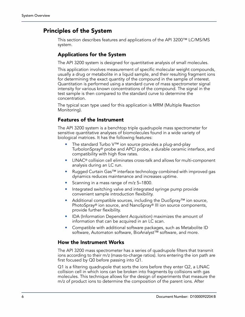
passing through Q2 the ions enter Q3 for additional filtering, and then enter the detector. In the detector, the ions create a current that is converted into a voltage pulse. The voltage pulses leaving the detector are directly proportional to the quantity of ions entering the detector. The instrument monitors these voltage pulses and converts the information into a signal. The signal represents the ion intensity for a particular m/z and the instrument displays this formation as a mass spectrum. For more information, see the following figure, Figure 1-2 Ion optics path.
Figure 1-2 Ion optics path
The API 3200 system uses the Turbo V ion source to produce ions from liquid samples. The Turbo V source can use either the TurboIonSpray probe or the APCI (atmospheric pressure chemical ionization) probe. The instrument is configured to perform complex MS/MS analysis, but for less rigorous analytical requirements it can perform single MS scans.
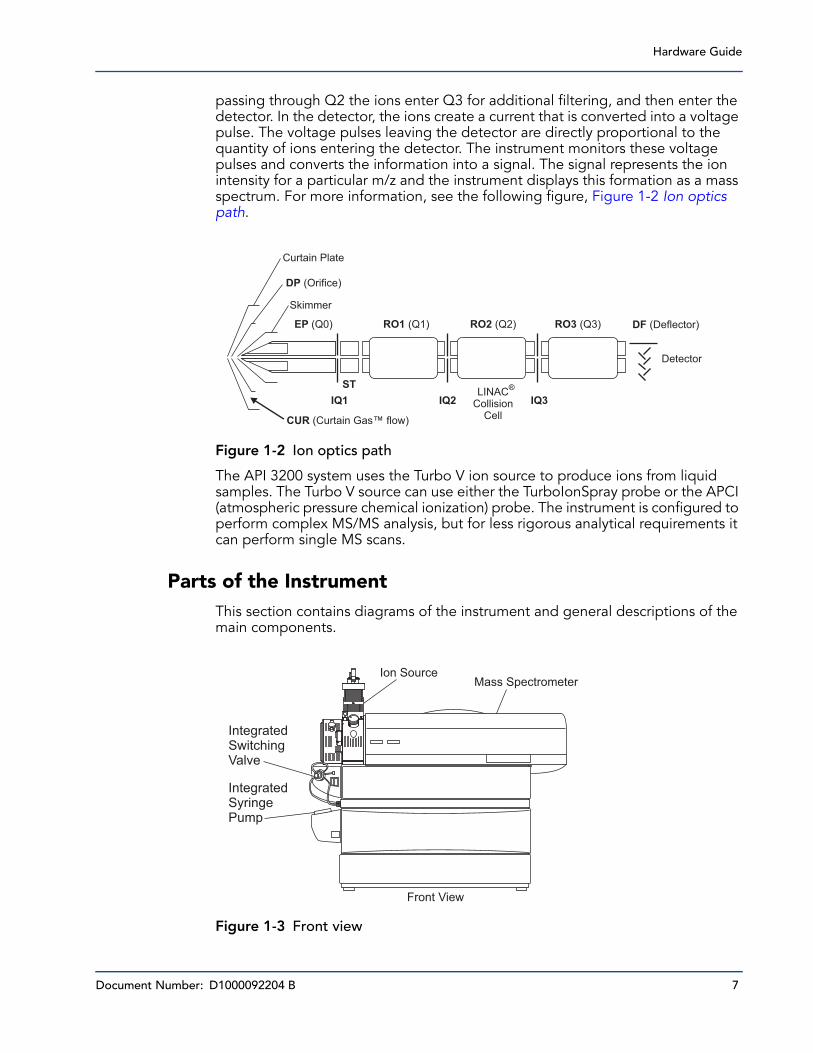
Parts of the InstrumentThis section contains diagrams of the instrument and general descriptions of the main components.
Figure 1-3 Front view
Curtain Plate
DP (Orifice)
Skimmer
IQ1 IQ2LINAC
®
CollisionCell
IQ3
ST
DF (Deflector)
Detector
CUR (Curtain Gas™ flow)
EP (Q0) RO1 (Q1) RO2 (Q2) RO3 (Q3)
Front View
Mass SpectrometerIon Source
IntegratedSwitchingValve
IntegratedSyringePump
System Overview
8 Document Number: D1000092204 B
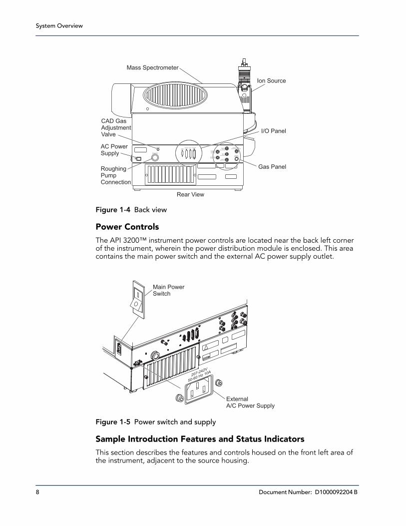
Figure 1-4 Back view
Power Controls
The API 3200™ instrument power controls are located near the back left corner of the instrument, wherein the power distribution module is enclosed. This area contains the main power switch and the external AC power supply outlet.
Figure 1-5 Power switch and supply
Sample Introduction Features and Status Indicators
This section describes the features and controls housed on the front left area of the instrument, adjacent to the source housing.
SHEATHGAS
MAX 105 PSIG
CAD
GASMAX 60 PSIG
VALVEWASTE OUT
EXHAUST
WASTE OUT
CURTAIN GASSUPPLY
Max 60 PSIG
GAS 1 / GAS 2
Max 105 PSIG
EXHAUST SUPPLY
MIN 55 PSIG MAX 60 PSIGSERIAL
SOURCESCAD GAS
BACKING PUMP
AUX I/O IEEE-4888
Rear View
Ion Source
Mass Spectrometer
I/O Panel
Gas PanelRoughingPumpConnection
AC PowerSupply
CAD GasAdjustmentValve
Main PowerSwitch
207-242V
50-60 Hz 10A
ExternalA/C Power Supply

Hardware Guide
Document Number: D1000092204 B 9
The Instrument Status lights indicate the status of the instrument vacuum. When the operational vacuum conditions are satisfied and the instrument is in analysis mode, the Ready light (green) is illuminated and the Fault light (red) is extinguished. The Fault light flashes when a vacuum fault is detected. In Pump-Down mode, the Ready light flashes for the duration of the sequence.
Directly below the source housing is a set of conveniently integrated sample introduction features. An integrated switching valve with associated Load and Inject buttons (marked A and B, respectively) can be used as a manual injector when optimizing for an analyte using FIA, or for diverting LC flow when any precipitate or salts initially come off the LC column. Below that, an integrated syringe pump is available for infusing standards when calibrating the instrument or optimizing for an analyte.
Figure 1-6 Sample introduction features and status indicators
I/O Panel
The input/output panel is located at the center back of the chassis. This panel contains several connection ports for the system:
• The IEEE-488 (GPIB) port provides a connection to the system’s computer.
LOAD INJECT
A B
IntegratedSwitchingValve
IntegratedSyringePump
INSTRUMENT STAUS
INSTRUMENT STATUS
FAULT
FAULT
READY
READY
LOAD INJECT
A B

System Overview
10 Document Number: D1000092204 B
• The sources port facilitates communication to optional ion sources, such as the control valve for the DuoSpray™ ion source, or provision of 24 VDC for the PhotoSpray® ion source.
• The AUX I/O outlet allows for communication with necessary peripheral devices, such as autosamplers or UV detectors.
• A serial port provides a connection point for additional device communications.
Figure 1-7 I/O panel
Gas Panel
The gas panel houses the gas supply connections and the external connections for the source exhaust system.
I/O Panel
SERIAL
SOURCES AUX I/O IEEE-488
Hardware Guide
Document Number: D1000092204 B 11
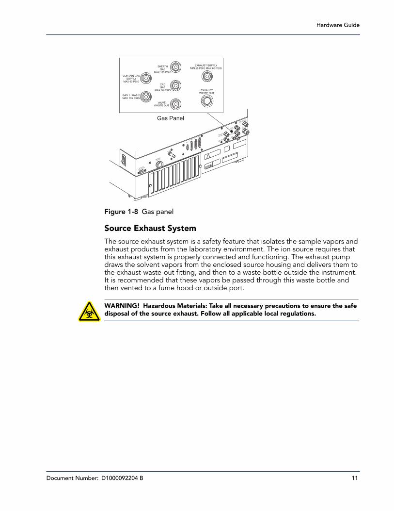
Figure 1-8 Gas panel
Source Exhaust System
The source exhaust system is a safety feature that isolates the sample vapors and exhaust products from the laboratory environment. The ion source requires that this exhaust system is properly connected and functioning. The exhaust pump draws the solvent vapors from the enclosed source housing and delivers them to the exhaust-waste-out fitting, and then to a waste bottle outside the instrument. It is recommended that these vapors be passed through this waste bottle and then vented to a fume hood or outside port.
WARNING! Hazardous Materials: Take all necessary precautions to ensure the safe disposal of the source exhaust. Follow all applicable local regulations.
EXHAUST SUPPLY
MIN55 PSIG
MAX 60 PSIG
SHEATH
GAS
MAX 105 PSIG
CAD
GAS
MAX 60 PSIG
CAD GAS
VALVE
WASTE OUT
EXHAUST
WASTE OUT
CURTAIN GAS
SUPPLY
Max 60 PSIG
GAS 1 / GAS 2
Max 105 PSIG
SERIAL
SOURCESAUX I/O
IEEE-488
207-242V
50-60 Hz 10A
BACKING
PUMP
Gas Panel
SHEATHGAS
MAX 105 PSIG
CADGAS
MAX 60 PSIG
VALVEWASTE OUT
EXHAUSTWASTE OUT
CURTAIN GASSUPPLY
MAX 60 PSIG
GAS 1 / GAS 2MAX 105 PSIG
EXHAUST SUPPLYMIN 55 PSIG MAX 60 PSIG

System Overview
12 Document Number: D1000092204 B
Figure 1-9 Source exhaust system
A filtered nitrogen or zero air gas supply (oil free) is delivered to the source exhaust pump at pressures indicated on the gas panel at the back of the instrument. The preceding figure shows the exhaust supply connection points for the API 3200 instrument.
Vacuum Chamber
The vacuum chamber houses the mass filter rail, including the ion optics, the quadrupole rod sets, the collision cell, and the ion detector.
Shutting Down and Turning on the SystemUse the following procedures if you need to shut down or turn on the system.
To shut down the system
1. In the Analyst® software, complete or stop any ongoing scans.
2. Turn off the sample flow to the instrument.
EXHAUST SUPPLY
MIN55 PSIG
MAX 60 PSIG
SHEATH
GAS
MAX 105 PSIG
CAD
GAS
MAX 60 PSIG
CAD GAS
VALVE
WASTE OUT
EXHAUST
WASTE OUT
CURTAIN GAS
SUPPLY
Max 60 PSIG
GAS 1 / GAS 2
Max 105 PSIG
SERIAL
SOURCESAUX I/O
IEEE-488
207-242V
50-60 Hz 10A
BACKING
PUMP
Gas Panel
Front BulkheadAssembly
PressureSwitch
VenturiPump
Exhaust Waste Out
Exhaust Supply
Ion Source
EXHAUST SUPPLYMIN 55 PSIG MAX 60 PSIG
SHEATHGAS
MAX 105 PSIG
CADGAS
MAX 60 PSIG
VALVEWASTE OUT
EXHAUSTWASTE OUT
CURTAIN GASSUPPLY
MAX 60 PSIG
GAS 1 / GAS 2MAX 105 PSIG
Hardware Guide
Document Number: D1000092204 B 13
CAUTION! Potential Instrument Damage: Shut off the sample flow before you shut down the instrument.
3. In the Analyst software, deactivate the hardware profile and then close the application software.
4. Stop the Analyst® Service. (See the Software Reference Guide for the Analyst software.)
CAUTION! Leave the roughing pump running for a minimum of 15 minutes after turning off the instrument’s main power switch. When the main power switch is turned off, the turbo pumps continue to rotate without power for a few minutes and continue to provide vacuum to the vacuum chamber. If, during this time, the roughing pump is turned off, the pressure in the vacuum line between the roughing pump and the turbo pumps increases. The increase in back pressure can create an incorrect load on the turbo pumps’ bearings and can cause a catastrophic failure of the turbo pumps.
CAUTION! If the instrument is to be shut down for any length of time, we recommend that the vacuum chamber be vented to prevent exhaust from the roughing pump being sucked back into the vacuum chamber. To vent the vacuum chamber, follow steps 5 to 7.
CAUTION! If the vacuum chamber is not going to be vented while the instrument is shut down, we recommend the roughing pump remain turned on to prevent the pump exhaust from being sucked back into the vacuum chamber. If you do not want to vent the vacuum chamber, skip steps 6 and 7.
5. Turn off the main power to the instrument. As you face the instrument where the instrument name is visible and with the source to your left, the switch is located on the bulkhead at the back right corner of the chassis.
6. After fifteen minutes, turn off the roughing pump. The power switch is located beside the power supply input attachment on the roughing pump.
7. Let the vacuum chamber vent naturally through the orifice for ten minutes to allow the instrument to reach atmospheric pressure.
8. Unplug the mains power cord to the instrument from the rear bulkhead near the main power switch for the instrument.
To turn on the system
Certain conditions outside the direct control of the instrument firmware must be satisfied before the turbo pumps will be initiated. The Curtain Gas™ supply must be turned on at the source, and the roughing pump must be turned on manually.
Note: The roughing pump has its own power toggle switch and must be turned off manually. The roughing pump is not controlled remotely by the system controller.

System Overview
14 Document Number: D1000092204 B
Interlocks (pressure switches) monitored by the firmware detect if the Curtain Gas supply and the roughing pump are switched on. If the interlocks are not satisfied, the turbo pumps are not initiated.
CAUTION! If the ion source is removed, the system electronics will be disabled, interrupting any data acquisition tasks. The turbo pump and the vacuum system will not be affected.
1. Turn on the roughing pump, if it was turned off. The power switch is located beside the power supply input attachment on the roughing pump.
2. Make sure that all gas supplies are flowing correctly to the instrument.
3. Plug the mains power cord into the bulkhead.
4. Turn on the main power switch.
5. Make sure that the GPIB (general purpose interface bus) cable is connected to both the instrument and the computer.
6. Turn on the computer, if it was turned off, and then start the Analyst® software.
Instrument Safe FluidsThe following fluids can safely be used with the instrument:
• Methanol (0 to 100%)• Acetonitrile (0 to 100%)• Water • Formic acid (0 to 1%)• Ammonium acetate (0 to 1%)
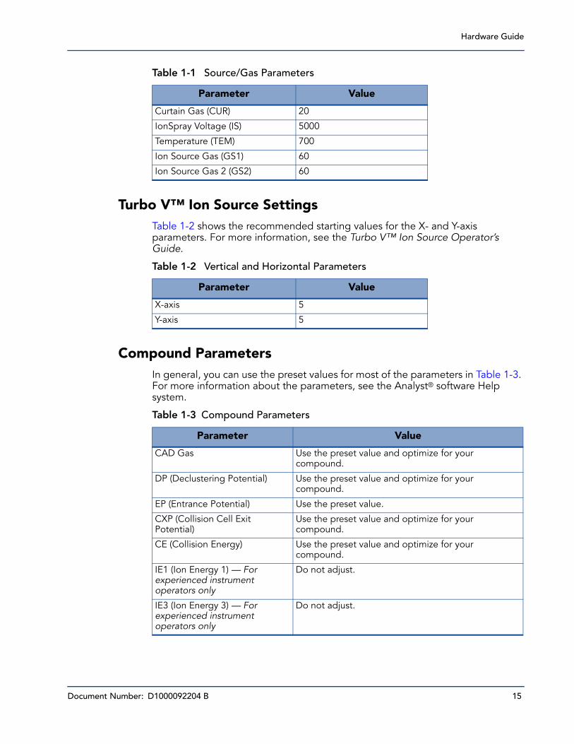
Source/Gas ParametersThe parameters in Table 1-1 are optimized for different LC conditions involving flow rate. For more information about the parameters, see the Analyst® software Help system.
Note: The roughing pump has its own power toggle switch and must be turned on manually. The roughing pump is not controlled remotely by the system controller.
Note: This list is not complete. If you are uncertain about a specific fluid, do not use the fluid until confirmation is received from AB SCIEX that it will not present a hazard.
Note: We recommend that you run the instrument with the Curtain Gas™ flow set to at least 20 to maintain good instrument performance.
Hardware Guide
Document Number: D1000092204 B 15
Turbo V™ Ion Source SettingsTable 1-2 shows the recommended starting values for the X- and Y-axis parameters. For more information, see the Turbo V™ Ion Source Operator’s Guide.
Compound ParametersIn general, you can use the preset values for most of the parameters in Table 1-3. For more information about the parameters, see the Analyst® software Help system.
Table 1-1 Source/Gas Parameters
Parameter Value
Curtain Gas (CUR) 20
IonSpray Voltage (IS) 5000
Temperature (TEM) 700
Ion Source Gas (GS1) 60
Ion Source Gas 2 (GS2) 60
Table 1-2 Vertical and Horizontal Parameters
Parameter Value
X-axis 5
Y-axis 5
Table 1-3 Compound Parameters
Parameter Value
CAD Gas Use the preset value and optimize for your compound.
DP (Declustering Potential) Use the preset value and optimize for your compound.
EP (Entrance Potential) Use the preset value.
CXP (Collision Cell Exit Potential)
Use the preset value and optimize for your compound.
CE (Collision Energy) Use the preset value and optimize for your compound.
IE1 (Ion Energy 1) — For experienced instrument operators only
Do not adjust.
IE3 (Ion Energy 3) — For experienced instrument operators only
Do not adjust.

System Overview
16 Document Number: D1000092204 B
Related DocumentationThe guides and tutorials for the instrument and the Analyst software are installed automatically with the software and are available from the Start menu: All Programs > AB SCIEX. A complete list of the available documentation can be found in the online Help. To view the Analyst software Help, press F1.
Technical SupportAB SCIEX and its representatives maintain a staff of fully-trained service and technical specialists located throughout the world. They can answer questions about the instrument or any technical issues that may arise. For more information, visit the web site at http://www.absciex.com.
Document Number: D1000092204 B 17
23200 Series Parameters
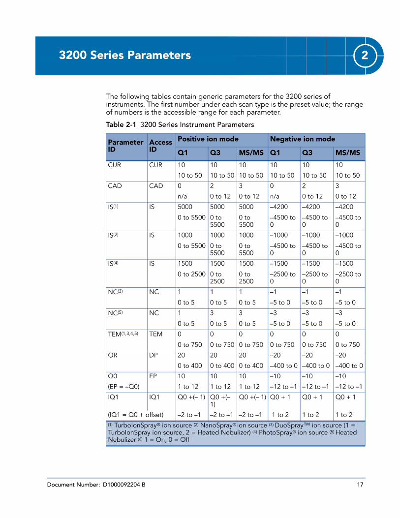
The following tables contain generic parameters for the 3200 series of instruments. The first number under each scan type is the preset value; the range of numbers is the accessible range for each parameter.
Table 2-1 3200 Series Instrument Parameters
Parameter ID
Access ID
Positive ion mode Negative ion mode
Q1 Q3 MS/MS Q1 Q3 MS/MS
CUR CUR 10 10 10 10 10 10
10 to 50 10 to 50 10 to 50 10 to 50 10 to 50 10 to 50
CAD CAD 0 2 3 0 2 3
n/a 0 to 12 0 to 12 n/a 0 to 12 0 to 12
IS(1) IS 5000 5000 5000 –4200 –4200 –4200
0 to 5500 0 to 5500
0 to 5500
–4500 to 0
–4500 to 0
–4500 to 0
IS(2) IS 1000 1000 1000 –1000 –1000 –1000
0 to 5500 0 to 5500
0 to 5500
–4500 to 0
–4500 to 0
–4500 to 0
IS(4) IS 1500 1500 1500 –1500 –1500 –1500
0 to 2500 0 to 2500
0 to 2500
–2500 to 0
–2500 to 0
–2500 to 0
NC(3) NC 1 1 1 –1 –1 –1
0 to 5 0 to 5 0 to 5 –5 to 0 –5 to 0 –5 to 0
NC(5) NC 1 3 3 –3 –3 –3
0 to 5 0 to 5 0 to 5 –5 to 0 –5 to 0 –5 to 0
TEM(1,3,4,5) TEM 0 0 0 0 0 0
0 to 750 0 to 750 0 to 750 0 to 750 0 to 750 0 to 750
OR DP 20 20 20 –20 –20 –20
0 to 400 0 to 400 0 to 400 –400 to 0 –400 to 0 –400 to 0
Q0 EP 10 10 10 –10 –10 –10
(EP = –Q0) 1 to 12 1 to 12 1 to 12 –12 to –1 –12 to –1 –12 to –1
IQ1 IQ1 Q0 +(– 1) Q0 +(– 1)
Q0 +(– 1) Q0 + 1 Q0 + 1 Q0 + 1
(IQ1 = Q0 + offset) –2 to –1 –2 to –1 –2 to –1 1 to 2 1 to 2 1 to 2(1) TurboIonSpray® ion source (2) NanoSpray® ion source (3) DuoSpray™ ion source (1 = TurboIonSpray ion source, 2 = Heated Nebulizer) (4) PhotoSpray® ion source (5) Heated Nebulizer (6) 1 = On, 0 = Off

3200 Series Parameters
18 Document Number: D1000092204 B
ST ST Q0 +(–5) Q0 +(–5)
Q0 +(–5) Q0 + 5 Q0 + 5 Q0 + 5
(ST = Q0 + offset) –8 to –2 –8 to –2 –8 to –2 2 to 8 2 to 8 2 to 8
RO1 IE1 1 n/a 1 –1 n/a –1
(IE1 = Q0 – RO1) 0.5 to 2 0.5 to 2 –2 to –0.5
–2 to –0.5
RO1 RO1 n/a Q0 + (– 2)
n/a n/a Q0 + 2 n/a
(RO1 = Q0 + offset) –2 to –0.5
0.5 to 2
IQ2 CEP Mass Dependent
n/a Mass Dependent
Mass Dependent
n/a Mass Dependent
(CEP = Q0 – IQ2) 0 to 188 0 to 188 –188 to 0 –188 to 0
IQ2 IQ2 n/a RO2 + 0 n/a n/a RO2 + 0 n/a
(IQ2 = RO2 + offset) 0 to 2 –2 to 0
RO2 CE n/a n/a 30 n/a n/a –30
(CE = Q0 – RO2) 5 to 130 –130 to –5
RO2 RO2 –100 –20 n/a 100 20 n/a
–150 to –20
–130 to –5
20 to 150 5 to 130
IQ3 CXP n/a Mass Dependent
5 n/a Mass Dependent
–5
(CXP = RO2 – IQ3) 0 to 58 0 to 58 –58 to 0 –58 to 0
IQ3 IQ3 –125 n/a n/a 125 n/a n/a
–200 to –100
100 to 200
RO3 IE3 n/a 4 4 n/a –4 –4
(IE3 = RO2 – RO3) 0.5 to 8 0.5 to 8 –8 to –0.5 –8 to –0.5
RO3 RO3 –150 n/a n/a 150 n/a n/a
–200 to –150
150 to 200
EX EX –200 –200 –200 200 200 200
n/a n/a n/a n/a n/a n/a
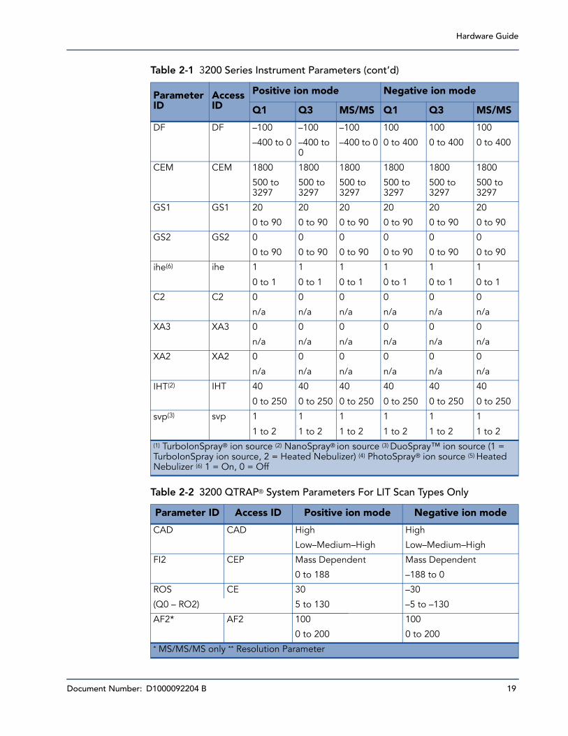
Table 2-1 3200 Series Instrument Parameters (cont’d)
Parameter ID
Access ID
Positive ion mode Negative ion mode
Q1 Q3 MS/MS Q1 Q3 MS/MS
(1) TurboIonSpray® ion source (2) NanoSpray® ion source (3) DuoSpray™ ion source (1 = TurboIonSpray ion source, 2 = Heated Nebulizer) (4) PhotoSpray® ion source (5) Heated Nebulizer (6) 1 = On, 0 = Off
Hardware Guide
Document Number: D1000092204 B 19
DF DF –100 –100 –100 100 100 100
–400 to 0 –400 to 0
–400 to 0 0 to 400 0 to 400 0 to 400
CEM CEM 1800 1800 1800 1800 1800 1800
500 to 3297
500 to 3297
500 to 3297
500 to 3297
500 to 3297
500 to 3297
GS1 GS1 20 20 20 20 20 20
0 to 90 0 to 90 0 to 90 0 to 90 0 to 90 0 to 90
GS2 GS2 0 0 0 0 0 0
0 to 90 0 to 90 0 to 90 0 to 90 0 to 90 0 to 90
ihe(6) ihe 1 1 1 1 1 1
0 to 1 0 to 1 0 to 1 0 to 1 0 to 1 0 to 1
C2 C2 0 0 0 0 0 0
n/a n/a n/a n/a n/a n/a
XA3 XA3 0 0 0 0 0 0
n/a n/a n/a n/a n/a n/a
XA2 XA2 0 0 0 0 0 0
n/a n/a n/a n/a n/a n/a
IHT(2) IHT 40 40 40 40 40 40
0 to 250 0 to 250 0 to 250 0 to 250 0 to 250 0 to 250
svp(3) svp 1 1 1 1 1 1
1 to 2 1 to 2 1 to 2 1 to 2 1 to 2 1 to 2
Table 2-2 3200 QTRAP® System Parameters For LIT Scan Types Only
Parameter ID Access ID Positive ion mode Negative ion mode
CAD CAD High High
Low–Medium–High Low–Medium–High
FI2 CEP Mass Dependent Mass Dependent
0 to 188 –188 to 0
ROS CE 30 –30
(Q0 – RO2) 5 to 130 –5 to –130
AF2* AF2 100 100
0 to 200 0 to 200* MS/MS/MS only ** Resolution Parameter
Table 2-1 3200 Series Instrument Parameters (cont’d)
Parameter ID
Access ID
Positive ion mode Negative ion mode
Q1 Q3 MS/MS Q1 Q3 MS/MS
(1) TurboIonSpray® ion source (2) NanoSpray® ion source (3) DuoSpray™ ion source (1 = TurboIonSpray ion source, 2 = Heated Nebulizer) (4) PhotoSpray® ion source (5) Heated Nebulizer (6) 1 = On, 0 = Off
3200 Series Parameters
20 Document Number: D1000092204 B
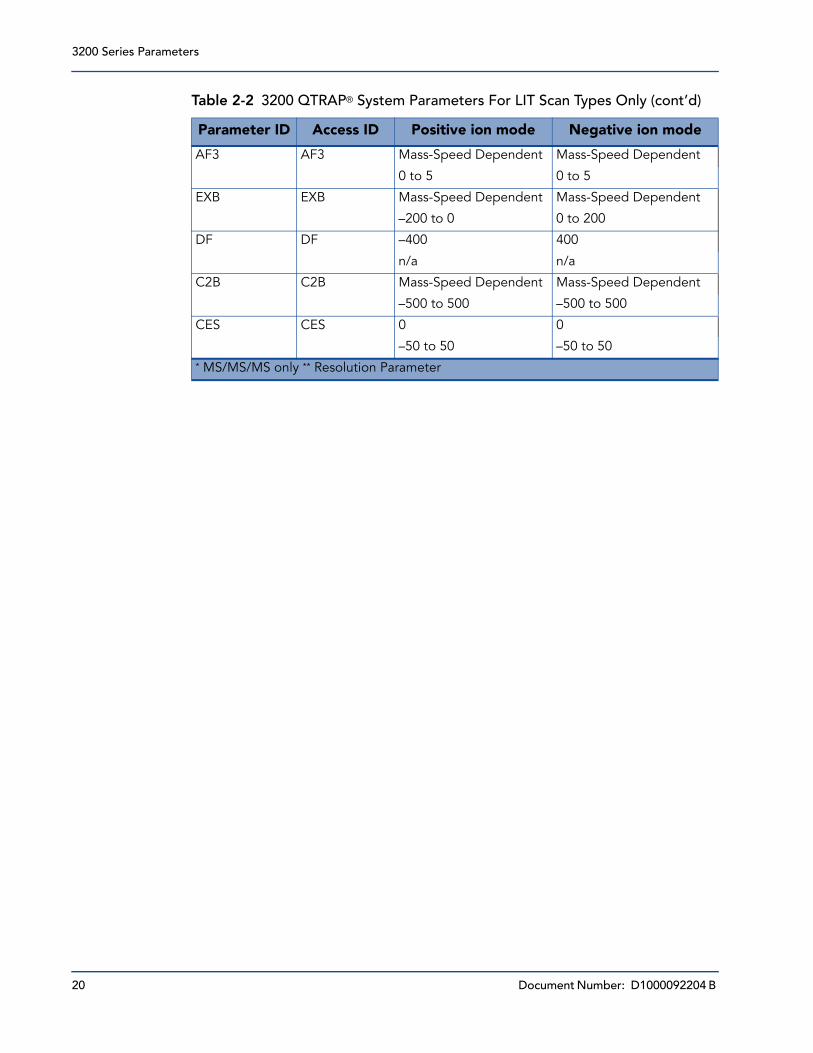
AF3 AF3 Mass-Speed Dependent Mass-Speed Dependent
0 to 5 0 to 5
EXB EXB Mass-Speed Dependent Mass-Speed Dependent
–200 to 0 0 to 200
DF DF –400 400
n/a n/a
C2B C2B Mass-Speed Dependent Mass-Speed Dependent
–500 to 500 –500 to 500
CES CES 0 0
–50 to 50 –50 to 50
Table 2-2 3200 QTRAP® System Parameters For LIT Scan Types Only (cont’d)
Parameter ID Access ID Positive ion mode Negative ion mode
* MS/MS/MS only ** Resolution Parameter