apm30h&tmc11h&ibbs200d&ibbs200t(ver.b) user guide(v200r303_11)
TRANSCRIPT

APM30H&TMC11H&IBBS200D&IBBS200T(Ver.B)V200R303
User Guide
Issue 11
Date 2011-06-10
HUAWEI TECHNOLOGIES CO., LTD.


Copyright © Huawei Technologies Co., Ltd. 2011. All rights reserved.No part of this document may be reproduced or transmitted in any form or by any means without prior writtenconsent of Huawei Technologies Co., Ltd. Trademarks and Permissions
and other Huawei trademarks are trademarks of Huawei Technologies Co., Ltd.All other trademarks and trade names mentioned in this document are the property of their respective holders. NoticeThe purchased products, services and features are stipulated by the contract made between Huawei and thecustomer. All or part of the products, services and features described in this document may not be within thepurchase scope or the usage scope. Unless otherwise specified in the contract, all statements, information,and recommendations in this document are provided "AS IS" without warranties, guarantees or representationsof any kind, either express or implied.
The information in this document is subject to change without notice. Every effort has been made in thepreparation of this document to ensure accuracy of the contents, but all statements, information, andrecommendations in this document do not constitute the warranty of any kind, express or implied.
Huawei Technologies Co., Ltd.Address: Huawei Industrial Base
Bantian, LonggangShenzhen 518129People's Republic of China
Website: http://www.huawei.com
Email: [email protected]
Issue 11 (2011-06-10) Huawei Proprietary and ConfidentialCopyright © Huawei Technologies Co., Ltd.
i


About This Document
PurposeThis document describes the functions, specifications, hardware, and cables of the APM30HVer.B, TMC11H Ver.B, IBBS200D Ver.B, and IBBS200T Ver.B. It also provides instructionsfor the hardware installation check and hardware maintenance.l The APM30H is the Advance Power Module with heat-exchanger cooler.l The TMC11H is the Transmission Cabinet of 11 U high with heat exchanger.l The IBBS200T B is the Integrated Battery Backup System with TEC cooler.l The IBBS200D is the Integrated Battery Backup System with direct ventilation.
Product VersionThe following table lists the product version related to this document.
Product Name Product Version
APM30H Ver.B(hereinafter referred to asAPM30H)
V200R303
TMC11H Ver.B(hereinafter referred to asTMC11H)
IBBS200T Ver.B(hereinafter referred to asIBBS200T)
IBBS200D Ver.B(hereinafter referred to asIBBS200D)
Intended Audience
This document is intended for:
l System Engineersl Base station installation engineersl Site maintenance engineers
APM30H&TMC11H&IBBS200D&IBBS200T(Ver.B)User Guide About This Document
Issue 11 (2011-06-10) Huawei Proprietary and ConfidentialCopyright © Huawei Technologies Co., Ltd.
iii

Organization1 Changes in the APM30H&TMC11H&IBBS200D&IBBS200T(Ver.B) User Guide
This describes the changes in the APM30H&TMC11H&IBBS200D&IBBS200T(Ver.B) UserGuide.
2 Overview of the APM30H Family
The APM30H family consists of the APM30H, TMC11H, IBBS200T, and IBBS200D.
3 Overview of the APM30H
This describes the exterior, structure, and components of the APM30H.
4 Overview of the IBBS200T
This describes the exterior, structure, components, and cables of the IBBS200T.
5 Overview of the IBBS200D
This describes the exterior, structure, components, and cables of the IBBS200D.
6 Overview of the TMC11H
This describes the exterior, structure, components, and cables of the TMC11H.
7 SLPU
The signal lightning protection unit (SLPU), which can be optionally configured with the UFLP,UELP, or USLP2, provides the signal surge protection.
8 Maintaining the Hardware for the APM30H&TMC11H&IBBS200D&IBBS200T
If the APM30H&TMC11H&IBBS200D&IBBS200T must be powered off for maintenance, theduration of the power-off state cannot exceed 48 hours.
ConventionsSymbol Conventions
The symbols that may be found in this document are defined as follows.
Symbol Description
Indicates a hazard with a high level of risk, which if notavoided, will result in death or serious injury.
Indicates a hazard with a medium or low level of risk, whichif not avoided, could result in minor or moderate injury.
Indicates a potentially hazardous situation, which if notavoided, could result in equipment damage, data loss,performance degradation, or unexpected results.
Indicates a tip that may help you solve a problem or savetime.
About This DocumentAPM30H&TMC11H&IBBS200D&IBBS200T(Ver.B)
User Guide
iv Huawei Proprietary and ConfidentialCopyright © Huawei Technologies Co., Ltd.
Issue 11 (2011-06-10)
Symbol Description
Provides additional information to emphasize or supplementimportant points of the main text.
General Conventions
The general conventions that may be found in this document are defined as follows.
Convention Description
Times New Roman Normal paragraphs are in Times New Roman.
Boldface Names of files, directories, folders, and users are inboldface. For example, log in as user root.
Italic Book titles are in italics.
Courier New Examples of information displayed on the screen are inCourier New.
Command Conventions
The command conventions that may be found in this document are defined as follows.
Convention Description
Boldface The keywords of a command line are in boldface.
Italic Command arguments are in italics.
[ ] Items (keywords or arguments) in brackets [ ] are optional.
{ x | y | ... } Optional items are grouped in braces and separated byvertical bars. One item is selected.
[ x | y | ... ] Optional items are grouped in brackets and separated byvertical bars. One item is selected or no item is selected.
{ x | y | ... }* Optional items are grouped in braces and separated byvertical bars. A minimum of one item or a maximum of allitems can be selected.
[ x | y | ... ]* Optional items are grouped in brackets and separated byvertical bars. Several items or no item can be selected.
GUI Conventions
The GUI conventions that may be found in this document are defined as follows.
APM30H&TMC11H&IBBS200D&IBBS200T(Ver.B)User Guide About This Document
Issue 11 (2011-06-10) Huawei Proprietary and ConfidentialCopyright © Huawei Technologies Co., Ltd.
v
Convention Description
Boldface Buttons, menus, parameters, tabs, window, and dialog titlesare in boldface. For example, click OK.
> Multi-level menus are in boldface and separated by the ">"signs. For example, choose File > Create > Folder.
Keyboard Operations
The keyboard operations that may be found in this document are defined as follows.
Format Description
Key Press the key. For example, press Enter and press Tab.
Key 1+Key 2 Press the keys concurrently. For example, pressing Ctrl+Alt+A means the three keys should be pressed concurrently.
Key 1, Key 2 Press the keys in turn. For example, pressing Alt, A meansthe two keys should be pressed in turn.
Mouse Operations
The mouse operations that may be found in this document are defined as follows.
Action Description
Click Select and release the primary mouse button without movingthe pointer.
Double-click Press the primary mouse button twice continuously andquickly without moving the pointer.
Drag Press and hold the primary mouse button and move thepointer to a certain position.
About This DocumentAPM30H&TMC11H&IBBS200D&IBBS200T(Ver.B)
User Guide
vi Huawei Proprietary and ConfidentialCopyright © Huawei Technologies Co., Ltd.
Issue 11 (2011-06-10)
Contents
About This Document...................................................................................................................iii
1 Changes in the APM30H&TMC11H&IBBS200D&IBBS200T(Ver.B) User Guide........1-1
2 Overview of the APM30H Family...........................................................................................2-12.1 Functions of the APM30H, IBBS200T, IBBS200D, and TMC11H...............................................................2-22.2 Application Scenarios of the APM30H Family..............................................................................................2-62.3 Technical Specifications of the APM30H Family..........................................................................................2-8
2.3.1 Electrical Specifications of the APM30H and TMC11H.......................................................................2-92.3.2 Engineering Specifications of the APM30H, IBBS200T, IBBS200D, and TMC11H........................2-112.3.3 Surge Protection Specifications of the APM30H.................................................................................2-152.3.4 Environmental Requirements of the APM30H, IBBS200T, IBBS200D, and TMC11H.....................2-16
3 Overview of the APM30H........................................................................................................3-13.1 Exterior of the APM30H.................................................................................................................................3-23.2 Structure of the APM30H...............................................................................................................................3-23.3 Cable Connections of the APM30H................................................................................................................3-33.4 APM30H Components....................................................................................................................................3-5
3.4.1 Fan Box..................................................................................................................................................3-63.4.2 AC/DC Power System..........................................................................................................................3-153.4.3 Power Equipment (DC/DC).................................................................................................................3-253.4.4 Core of the Heat Exchanger.................................................................................................................3-283.4.5 Junction Box.........................................................................................................................................3-293.4.6 ELU......................................................................................................................................................3-303.4.7 Heater (Optional)..................................................................................................................................3-313.4.8 SOU (Optional)....................................................................................................................................3-323.4.9 Door Status Sensor...............................................................................................................................3-33
3.5 APM30H Cables...........................................................................................................................................3-343.5.1 PGND Cable.........................................................................................................................................3-353.5.2 Input Power Cables for the APM30H..................................................................................................3-363.5.3 Power Cable for the SOU.....................................................................................................................3-373.5.4 Power Cable for the Heater..................................................................................................................3-383.5.5 Power Cable for the Fan Box in the APM30H.....................................................................................3-393.5.6 ELU Signal Cable.................................................................................................................................3-403.5.7 APM30H Door Status Monitoring Cable.............................................................................................3-40
APM30H&TMC11H&IBBS200D&IBBS200T(Ver.B)User Guide Contents
Issue 11 (2011-06-10) Huawei Proprietary and ConfidentialCopyright © Huawei Technologies Co., Ltd.
vii
3.5.8 Monitoring Signal Cable for the Fan on the Front Door......................................................................3-413.5.9 Environment Monitoring Signal Cable................................................................................................3-423.5.10 Monitoring Signal Transfer Cable......................................................................................................3-44
4 Overview of the IBBS200T.......................................................................................................4-14.1 Exterior of the IBBS200T...............................................................................................................................4-24.2 Structure of the IBBS200T..............................................................................................................................4-24.3 Cable Connections of the IBBS200T..............................................................................................................4-34.4 IBBS200T Components..................................................................................................................................4-4
4.4.1 TEC Cooler............................................................................................................................................4-54.4.2 Power Distribution Box..........................................................................................................................4-64.4.3 CMUA....................................................................................................................................................4-84.4.4 Storage Battery.....................................................................................................................................4-134.4.5 ELU......................................................................................................................................................4-144.4.6 Door Status Sensor...............................................................................................................................4-154.4.7 Temperature Sensor for the Storage Batteries......................................................................................4-16
4.5 IBBS200T Cables..........................................................................................................................................4-174.5.1 PGND Cable.........................................................................................................................................4-184.5.2 Equipotential Cable..............................................................................................................................4-194.5.3 Power Cables for the Storage Batteries................................................................................................4-194.5.4 Power Cables for the TEC Cooler........................................................................................................4-204.5.5 ELU Signal Cable.................................................................................................................................4-214.5.6 Door Status Monitoring Cable.............................................................................................................4-224.5.7 Monitoring Signal Cable for the Storage Battery Cabinet...................................................................4-22
5 Overview of the IBBS200D.......................................................................................................5-15.1 Exterior of the IBBS200D Cabinet.................................................................................................................5-25.2 IBBS200D Structure.......................................................................................................................................5-25.3 Cable Connections of the IBBS200D..............................................................................................................5-35.4 IBBS200D Components..................................................................................................................................5-4
5.4.1 Fan Box..................................................................................................................................................5-55.4.2 Power Distribution Box..........................................................................................................................5-65.4.3 CMUA....................................................................................................................................................5-85.4.4 Storage Battery.....................................................................................................................................5-135.4.5 ELU......................................................................................................................................................5-145.4.6 Heating Film.........................................................................................................................................5-155.4.7 Door Status Sensor...............................................................................................................................5-165.4.8 Temperature Sensor for the Storage Batteries......................................................................................5-17
5.5 IBBS200D Cables.........................................................................................................................................5-185.5.1 PGND Cable.........................................................................................................................................5-195.5.2 Equipotential Cable..............................................................................................................................5-205.5.3 Power Cables for the Storage Batteries................................................................................................5-205.5.4 Power Cables for the Fans in the IBBS200D.......................................................................................5-215.5.5 Power Cable for the Heating Film........................................................................................................5-22
ContentsAPM30H&TMC11H&IBBS200D&IBBS200T(Ver.B)
User Guide
viii Huawei Proprietary and ConfidentialCopyright © Huawei Technologies Co., Ltd.
Issue 11 (2011-06-10)
5.5.6 ELU Signal Cable.................................................................................................................................5-235.5.7 Door Status Monitoring Cable.............................................................................................................5-245.5.8 Monitoring Signal Cable for the Storage Battery Cabinet...................................................................5-24
6 Overview of the TMC11H........................................................................................................6-16.1 Exterior of the TMC11H.................................................................................................................................6-26.2 Structure of the TMC11H............................................................................................................................... 6-26.3 Cable Connections of the TMC11H................................................................................................................6-36.4 TMC11H Components....................................................................................................................................6-4
6.4.1 Fan Box..................................................................................................................................................6-56.4.2 DCDU-03.............................................................................................................................................6-136.4.3 Core of the Heat Exchanger.................................................................................................................6-166.4.4 Junction Box.........................................................................................................................................6-176.4.5 ELU......................................................................................................................................................6-186.4.6 Heater (Optional)..................................................................................................................................6-196.4.7 Door Status Sensor...............................................................................................................................6-20
6.5 TMC11H Cables...........................................................................................................................................6-216.5.1 Equipotential Cable..............................................................................................................................6-216.5.2 Input Power Cable for the TMC11H....................................................................................................6-226.5.3 Power Cable for the Fan Box in the TMC11H.....................................................................................6-236.5.4 ELU Signal Cable.................................................................................................................................6-236.5.5 Door Status Monitoring Cable.............................................................................................................6-246.5.6 Monitoring Signal Cable for the Fan on the Front Door......................................................................6-25
7 SLPU.............................................................................................................................................7-17.1 Exterior of SLPU.............................................................................................................................................7-27.2 Configuration of the SLPU............................................................................................................................. 7-27.3 UELP...............................................................................................................................................................7-37.4 UFLP...............................................................................................................................................................7-57.5 USLP2.............................................................................................................................................................7-6
8 Maintaining the Hardware for the APM30H&TMC11H&IBBS200D&IBBS200T........8-18.1 Routine Maintenance.......................................................................................................................................8-38.2 Replacing the PMU.........................................................................................................................................8-38.3 Replacing the PSU.......................................................................................................................................... 8-68.4 Replacing the EPS Subrack.............................................................................................................................8-88.5 Replacing the AC Surge Protector................................................................................................................8-118.6 Replacing the Fuse........................................................................................................................................8-138.7 Replacing the Fan Box in the APM30H .......................................................................................................8-168.8 Replacing the Fan on the Front Door of the APM30H.................................................................................8-18
8.8.1 Querying the Type of Fan....................................................................................................................8-188.8.2 Replacing the Fan for the Modularized Heat Exchanger Installed on the Front Door.........................8-198.8.3 Replacing the Fan for the Non-Modularized Heat Exchanger Installed on the Front Door................8-23
8.9 Replacing the Heater.....................................................................................................................................8-26
APM30H&TMC11H&IBBS200D&IBBS200T(Ver.B)User Guide Contents
Issue 11 (2011-06-10) Huawei Proprietary and ConfidentialCopyright © Huawei Technologies Co., Ltd.
ix
8.10 Replacing the Fan Box in the TMC11H......................................................................................................8-288.11 Replacing the Batteries................................................................................................................................8-308.12 Replacing the TEC Cooler of the IBBS200T..............................................................................................8-328.13 Replacing the Fan on the Front Door of the IBBS200D.............................................................................8-358.14 Replacing the CMUA..................................................................................................................................8-388.15 Replacing the ELU......................................................................................................................................8-42
ContentsAPM30H&TMC11H&IBBS200D&IBBS200T(Ver.B)
User Guide
x Huawei Proprietary and ConfidentialCopyright © Huawei Technologies Co., Ltd.
Issue 11 (2011-06-10)

Figures
Figure 2-1 APM30H (stacked on the battery cabinet) working with a distributed base station.......................... 2-7Figure 2-2 APM30H working with a separated macro base station.....................................................................2-8Figure 3-1 Exterior of the APM30H.................................................................................................................... 3-2Figure 3-2 Internal structure of the APM30H......................................................................................................3-3Figure 3-3 Cable connections of the APM30H working with a distributed base station.....................................3-4Figure 3-4 Cable connections of the APM30H working with a separated macro base station............................3-5Figure 3-5 Fan Box...............................................................................................................................................3-6Figure 3-6 Fan......................................................................................................................................................3-7Figure 3-7 HPMI..................................................................................................................................................3-8Figure 3-8 Ports on the panel of an HPMI........................................................................................................... 3-8Figure 3-9 CMUA..............................................................................................................................................3-10Figure 3-10 Ports on a CMUA (plan view)........................................................................................................3-11Figure 3-11 Positions of the DIP switches on the CMUA (plan view)..............................................................3-14Figure 3-12 DIP switch settings of the CMUA in different cabinets.................................................................3-15Figure 3-13 Structure of the EPS subrack in a distributed base station.............................................................3-16Figure 3-14 Structure of the EPS subrack in a separated macro base station....................................................3-17Figure 3-15 PMU................................................................................................................................................3-19Figure 3-16 Ports, LEDs, and Switch on the front panel of a PMU...................................................................3-20Figure 3-17 Rear panel of a PMU......................................................................................................................3-21Figure 3-18 DIP switch on the right of a PMU..................................................................................................3-23Figure 3-19 Panel of the PSU (AC/DC).............................................................................................................3-24Figure 3-20 Power equipment (DC/DC)............................................................................................................3-25Figure 3-21 Panel of the PSU (DC/DC).............................................................................................................3-26Figure 3-22 Power Subrack (DC/DC)................................................................................................................3-27Figure 3-23 Core of the heat exchanger.............................................................................................................3-29Figure 3-24 Junction box....................................................................................................................................3-29Figure 3-25 Structure of the junction box..........................................................................................................3-30Figure 3-26 ELU................................................................................................................................................3-31Figure 3-27 Heater..............................................................................................................................................3-31Figure 3-28 SOU................................................................................................................................................3-32Figure 3-29 Different types of sockets...............................................................................................................3-33Figure 3-30 Magnet part of the door status sensor.............................................................................................3-33Figure 3-31 Switch part of the door status sensor..............................................................................................3-34
APM30H&TMC11H&IBBS200D&IBBS200T(Ver.B)User Guide Figures
Issue 11 (2011-06-10) Huawei Proprietary and ConfidentialCopyright © Huawei Technologies Co., Ltd.
xi
Figure 3-32 PGND cable for the cabinet............................................................................................................3-35Figure 3-33 PGND cable for the modules..........................................................................................................3-35Figure 3-34 220 V AC single-phase input power cable.....................................................................................3-36Figure 3-35 +24 V DC power cable...................................................................................................................3-36Figure 3-36 Power cable for the SOU................................................................................................................3-38Figure 3-37 Power cable for the heater..............................................................................................................3-39Figure 3-38 Power cable for the fan box in the APM30H.................................................................................3-39Figure 3-39 ELU signal cable............................................................................................................................3-40Figure 3-40 APM30H door status monitoring cable..........................................................................................3-41Figure 3-41 Monitoring signal cable for the fan on the front door....................................................................3-42Figure 3-42 Environment monitoring signal cable.............................................................................................3-43Figure 3-43 Monitoring signal transfer cable.....................................................................................................3-44Figure 4-1 Exterior of the IBBS200T...................................................................................................................4-2Figure 4-2 Internal structure of the IBBS200T....................................................................................................4-3Figure 4-3 Cable connections of the IBBS200T..................................................................................................4-4Figure 4-4 TEC cooler..........................................................................................................................................4-5Figure 4-5 PDB....................................................................................................................................................4-6Figure 4-6 External structure of a PDB................................................................................................................4-8Figure 4-7 CMUA................................................................................................................................................4-9Figure 4-8 Ports on a CMUA (plan view)............................................................................................................4-9Figure 4-9 Positions of the DIP switches on the CMUA (plan view)................................................................4-13Figure 4-10 DIP switch settings of the CMUA in different cabinets.................................................................4-13Figure 4-11 Exterior of the 12 V 92 Ah storage battery.....................................................................................4-14Figure 4-12 ELU................................................................................................................................................4-15Figure 4-13 Magnet part of the door status sensor.............................................................................................4-15Figure 4-14 Switch part of the door status sensor..............................................................................................4-16Figure 4-15 Installation position of the temperature sensor for the storage batteries in the IBBS200D...........4-16Figure 4-16 Installation position of the temperature sensor for the storage batteries in the IBBS200T............4-17Figure 4-17 PGND cable for the cabinet............................................................................................................4-18Figure 4-18 PGND cable for the modules..........................................................................................................4-18Figure 4-19 Equipotential cable.........................................................................................................................4-19Figure 4-20 Input power cables for the storage batteries...................................................................................4-19Figure 4-21 Power cable between the storage batteries and the copper bar in the junction box........................4-20Figure 4-22 Inter-battery connection copper bar................................................................................................4-20Figure 4-23 Input power cable for the TEC cooler............................................................................................4-21Figure 4-24 Power transfer cable for the TEC cooler........................................................................................4-21Figure 4-25 ELU signal cable............................................................................................................................4-21Figure 4-26 Door status monitoring cable..........................................................................................................4-22Figure 4-27 Monitoring signal cable for the storage battery cabinet.................................................................4-23Figure 5-1 Exterior of the IBBS200D cabinet......................................................................................................5-2Figure 5-2 Internal structure of an IBBS200D.....................................................................................................5-3Figure 5-3 Cable connections of the IBBS200D..................................................................................................5-4
FiguresAPM30H&TMC11H&IBBS200D&IBBS200T(Ver.B)
User Guide
xii Huawei Proprietary and ConfidentialCopyright © Huawei Technologies Co., Ltd.
Issue 11 (2011-06-10)
Figure 5-4 Fan box...............................................................................................................................................5-5Figure 5-5 PDB....................................................................................................................................................5-6Figure 5-6 External structure of a PDB................................................................................................................5-8Figure 5-7 CMUA................................................................................................................................................5-9Figure 5-8 Ports on a CMUA (plan view)............................................................................................................5-9Figure 5-9 Positions of the DIP switches on the CMUA (plan view)................................................................5-13Figure 5-10 DIP switch settings of the CMUA in different cabinets.................................................................5-13Figure 5-11 Exterior of the 12 V 92 Ah storage battery.....................................................................................5-14Figure 5-12 ELU................................................................................................................................................5-15Figure 5-13 Heating film....................................................................................................................................5-15Figure 5-14 Magnet part of the door status sensor.............................................................................................5-16Figure 5-15 Switch part of the door status sensor..............................................................................................5-17Figure 5-16 Installation position of the temperature sensor for the storage batteries in the IBBS200D...........5-17Figure 5-17 Installation position of the temperature sensor for the storage batteries in the IBBS200T............5-18Figure 5-18 PGND cable for the cabinet............................................................................................................5-19Figure 5-19 PGND cable for the modules..........................................................................................................5-19Figure 5-20 Equipotential cable.........................................................................................................................5-20Figure 5-21 Input power cables for the storage batteries...................................................................................5-20Figure 5-22 Power cable between the storage batteries and the copper bar in the junction box........................5-21Figure 5-23 Inter-battery connection copper bar................................................................................................5-21Figure 5-24 Input power cable for the fans in the IBBS200D...........................................................................5-22Figure 5-25 Power transfer cable for the fans in the IBBS200D.......................................................................5-22Figure 5-26 Power cable for the heating film.....................................................................................................5-22Figure 5-27 ELU signal cable............................................................................................................................5-23Figure 5-28 Door status monitoring cable..........................................................................................................5-24Figure 5-29 Monitoring signal cable for the storage battery cabinet.................................................................5-24Figure 6-1 TMC11H.............................................................................................................................................6-2Figure 6-2 Internal structure of the TMC11H......................................................................................................6-3Figure 6-3 Cable connections of the TMC11H....................................................................................................6-4Figure 6-4 Fan Box...............................................................................................................................................6-5Figure 6-5 Fan......................................................................................................................................................6-5Figure 6-6 HPMI..................................................................................................................................................6-7Figure 6-7 Ports on the panel of an HPMI...........................................................................................................6-7Figure 6-8 CMUA................................................................................................................................................6-9Figure 6-9 Ports on a CMUA (plan view)............................................................................................................6-9Figure 6-10 Positions of the DIP switches on the CMUA (plan view)..............................................................6-13Figure 6-11 DIP switch settings of the CMUA in different cabinets.................................................................6-13Figure 6-12 DCDU-03........................................................................................................................................6-14Figure 6-13 Ports on the panel of the DCDU-03................................................................................................6-15Figure 6-14 Core of the heat exchanger.............................................................................................................6-17Figure 6-15 Junction box....................................................................................................................................6-17Figure 6-16 Structure of the junction box..........................................................................................................6-18
APM30H&TMC11H&IBBS200D&IBBS200T(Ver.B)User Guide Figures
Issue 11 (2011-06-10) Huawei Proprietary and ConfidentialCopyright © Huawei Technologies Co., Ltd.
xiii
Figure 6-17 ELU................................................................................................................................................6-19Figure 6-18 Heater..............................................................................................................................................6-19Figure 6-19 Magnet part of the door status sensor.............................................................................................6-20Figure 6-20 Switch part of the door status sensor..............................................................................................6-20Figure 6-21 Equipotential cable.........................................................................................................................6-21Figure 6-22 Input power cable for the TMC11H (1)..........................................................................................6-22Figure 6-23 Input power cable for the TMC11H (2)..........................................................................................6-22Figure 6-24 Input power cable for the TMC11H (3)..........................................................................................6-23Figure 6-25 Power cable for the fan box in the TMC11H................................................................................. 6-23Figure 6-26 ELU signal cable............................................................................................................................ 6-24Figure 6-27 Door status monitoring cable..........................................................................................................6-24Figure 6-28 Monitoring signal cable for the fan on the front door.................................................................... 6-25Figure 7-1 SLPU..................................................................................................................................................7-2Figure 7-2 Slots of the SLPU...............................................................................................................................7-2Figure 7-3 UELP panel.........................................................................................................................................7-3Figure 7-4 DIP switch on the UELP....................................................................................................................7-4Figure 7-5 Panel of the UFLP..............................................................................................................................7-5Figure 7-6 Panel of the USLP2............................................................................................................................7-6Figure 7-7 Mapping relationship between the pins in the input and output ports on the USLP2........................7-6Figure 8-1 Installation position of the PMU........................................................................................................8-4Figure 8-2 Removing the PMU............................................................................................................................8-5Figure 8-3 The position of the DIP switch...........................................................................................................8-5Figure 8-4 Installing the PMU..............................................................................................................................8-6Figure 8-5 Installation position of the PSU..........................................................................................................8-7Figure 8-6 Removing the PSU.............................................................................................................................8-7Figure 8-7 Installing the PSU...............................................................................................................................8-8Figure 8-8 Replacing the EPS subrack...............................................................................................................8-10Figure 8-9 Installation position of the AC surge protector................................................................................ 8-12Figure 8-10 Removing the surge protector.........................................................................................................8-12Figure 8-11 Installation position of the fuse and spare fuse box........................................................................8-13Figure 8-12 Position of the extraction tool in the cabinet..................................................................................8-14Figure 8-13 Removing the faulty fuse................................................................................................................8-15Figure 8-14 Taking the spare fuse......................................................................................................................8-15Figure 8-15 Top view of the fan box in the APM30H.......................................................................................8-17Figure 8-16 Removing the fan box from the APM30H..................................................................................... 8-17Figure 8-17 Position of the fan in the APM30H................................................................................................8-19Figure 8-18 Remove the faulty cable for the fan................................................................................................8-20Figure 8-19 Removing the air duct.....................................................................................................................8-21Figure 8-20 Removing the heat exchanger.........................................................................................................8-21Figure 8-21 Removing the cover plate of the fan cavity....................................................................................8-22Figure 8-22 Removing the faulty fan.................................................................................................................8-22Figure 8-23 Position of the fan in the APM30H................................................................................................8-24
FiguresAPM30H&TMC11H&IBBS200D&IBBS200T(Ver.B)
User Guide
xiv Huawei Proprietary and ConfidentialCopyright © Huawei Technologies Co., Ltd.
Issue 11 (2011-06-10)

Figure 8-24 Removing the fan from the front door of the APM30H.................................................................8-25Figure 8-25 Removing the faulty heater.............................................................................................................8-27Figure 8-26 Installing the new heater.................................................................................................................8-27Figure 8-27 Top view of the fan box in the TMC11H.......................................................................................8-28Figure 8-28 Removing the fan box from the TMC11H.....................................................................................8-29Figure 8-29 Removing the cover plate from the batteries..................................................................................8-31Figure 8-30 Removing cables from the batteries...............................................................................................8-31Figure 8-31 Installation position of the TEC cooler...........................................................................................8-33Figure 8-32 Removing the retention screws from the CMUA...........................................................................8-34Figure 8-33 Removing the faulty TEC cooler....................................................................................................8-34Figure 8-34 Installation position of the fan on the front door of the IBBS200D...............................................8-36Figure 8-35 Removing the fan box from the IBBS200D...................................................................................8-37Figure 8-36 Removing the faulty fan.................................................................................................................8-37Figure 8-37 DIP settings of the CMUA in different cabinets............................................................................8-38Figure 8-38 Installation position of the CMUA.................................................................................................8-39Figure 8-39 Removing the fan box from the IBBS200D...................................................................................8-40Figure 8-40 Removing the CMUA box from the IBBS200T.............................................................................8-40Figure 8-41 Positions for attaching the bar codes of the CMUA.......................................................................8-41Figure 8-42 Position of the ELU in a TMC11H.................................................................................................8-42Figure 8-43 Position of the ELU in an IBBS200D or IBBS200T......................................................................8-43Figure 8-44 Removing the upper-left storage battery........................................................................................8-44Figure 8-45 Opening the housing of the ELU....................................................................................................8-44Figure 8-46 Removing the faulty ELIA.............................................................................................................8-44
APM30H&TMC11H&IBBS200D&IBBS200T(Ver.B)User Guide Figures
Issue 11 (2011-06-10) Huawei Proprietary and ConfidentialCopyright © Huawei Technologies Co., Ltd.
xv

Tables
Table 2-1 Functions of the APM30H...................................................................................................................2-2Table 2-2 DC power distribution functions of the APM30H...............................................................................2-3Table 2-3 Functions of the IBBS200T.................................................................................................................2-5Table 2-4 Functions of the IBBS200D.................................................................................................................2-5Table 2-5 Functions of the TMC11H...................................................................................................................2-6Table 2-6 Electrical specifications of the APM30H.............................................................................................2-9Table 2-7 Electrical specifications of the TMC11H...........................................................................................2-11Table 2-8 Engineering specifications of the APM30H......................................................................................2-12Table 2-9 Engineering specifications of the IBBS200T.....................................................................................2-13Table 2-10 Engineering specifications of the IBBS200D..................................................................................2-13Table 2-11 Engineering specifications of the TMC11H....................................................................................2-14Table 2-12 Surge protection specifications of the APM30H.............................................................................2-15Table 2-13 Environmental requirements of the APM30H.................................................................................2-16Table 2-14 Environmental requirements of the IBBS200T................................................................................2-17Table 2-15 Environmental requirements of the IBBS200D...............................................................................2-18Table 3-1 Technical specifications of the fan.......................................................................................................3-7Table 3-2 Specifications of the ports on the panel of an HPMI...........................................................................3-8Table 3-3 Ports on a CMUA...............................................................................................................................3-11Table 3-4 LEDs..................................................................................................................................................3-14Table 3-5 DC power distribution functions of the EPS subrack used for a distributed base station..................3-18Table 3-6 DC power distribution functions of the EPS used for a separated macro base station......................3-18Table 3-7 Ports and switch on a PMU................................................................................................................3-21Table 3-8 LEDs on the panel of a PMU.............................................................................................................3-22Table 3-9 LEDs on the panel of the PSU (AC/DC)...........................................................................................3-24Table 3-10 Components of the power equipment (DC/DC)...............................................................................3-25Table 3-11 LEDs on the panel of the PSU (DC/DC).........................................................................................3-26Table 3-12 Ports and terminals on the power subrack (DC/DC)........................................................................3-28Table 3-13 Technical specifications of the SOU................................................................................................3-32Table 3-14 PGND cables....................................................................................................................................3-35Table 3-15 Specifications of different types of AC input power cables.............................................................3-37Table 3-16 Pin assignment for the wires of the power cable for the SOU.........................................................3-38Table 3-17 Pin assignment for the wires of the power cable for the heater.......................................................3-39Table 3-18 Pin assignment for the wires of the ELU signal cable.....................................................................3-40
APM30H&TMC11H&IBBS200D&IBBS200T(Ver.B)User Guide Tables
Issue 11 (2011-06-10) Huawei Proprietary and ConfidentialCopyright © Huawei Technologies Co., Ltd.
xvii

Table 3-19 Pin assignment for the wires of the monitoring signal cable for the fan on the front door..............3-42Table 3-20 Pin assignment for the wires of the environment monitoring signal cable......................................3-43Table 3-21 Pin assignment of the monitoring signal transfer cable...................................................................3-45Table 4-1 Wiring terminals and switches on the panel of the PDB.....................................................................4-7Table 4-2 Ports on a CMUA...............................................................................................................................4-10Table 4-3 LEDs..................................................................................................................................................4-12Table 4-4 Technical specifications of the 12 V 92 Ah storage battery..............................................................4-14Table 4-5 PGND cables......................................................................................................................................4-18Table 4-6 Equipotential cable.............................................................................................................................4-19Table 4-7 Pin assignment for the wires of the ELU signal cable.......................................................................4-22Table 4-8 Pin assignment for the wires of the monitoring signal cable for the storage battery cabinet.............4-23Table 5-1 Wiring terminals and switches on the panel of the PDB.....................................................................5-6Table 5-2 Ports on a CMUA...............................................................................................................................5-10Table 5-3 LEDs..................................................................................................................................................5-12Table 5-4 Technical specifications of the 12 V 92 Ah storage battery..............................................................5-14Table 5-5 PGND cables......................................................................................................................................5-19Table 5-6 Equipotential cable.............................................................................................................................5-20Table 5-7 Pin assignment for the wires of the ELU signal cable.......................................................................5-23Table 5-8 Pin assignment for the wires of the monitoring signal cable for the storage battery cabinet.............5-24Table 6-1 Technical specifications of the fan.......................................................................................................6-6Table 6-2 Specifications of the ports on the panel of an HPMI...........................................................................6-7Table 6-3 Ports on a CMUA...............................................................................................................................6-10Table 6-4 LEDs..................................................................................................................................................6-12Table 6-5 DC power distribution functions of the DCDU-03............................................................................6-14Table 6-6 Ports on the panel of the DCDU-03...................................................................................................6-15Table 6-7 Equipotential cable.............................................................................................................................6-22Table 6-8 Pin assignment for the wires of the ELU signal cable.......................................................................6-24Table 6-9 Pin assignment for the wires of the monitoring signal cable for the fan on the front door................6-25Table 7-1 Configuration principles of the SLPU (1)............................................................................................7-3Table 7-2 Configuration principles of the SLPU (2)............................................................................................7-3Table 7-3 Ports of the UELP................................................................................................................................7-4Table 7-4 DIP switch on the UELP......................................................................................................................7-5Table 7-5 Ports on the panel of the UFLP............................................................................................................7-5Table 7-6 Ports on the panel of the USLP2..........................................................................................................7-6Table 7-7 Mapping relationship between the pins in the input and output ports on the USLP2..........................7-7Table 8-1 Routine maintenance items..................................................................................................................8-3
TablesAPM30H&TMC11H&IBBS200D&IBBS200T(Ver.B)
User Guide
xviii Huawei Proprietary and ConfidentialCopyright © Huawei Technologies Co., Ltd.
Issue 11 (2011-06-10)
1 Changes in theAPM30H&TMC11H&IBBS200D&IBBS200T
(Ver.B) User Guide
This describes the changes in the APM30H&TMC11H&IBBS200D&IBBS200T(Ver.B) UserGuide.
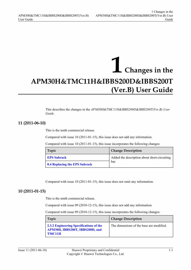
11 (2011-06-10)This is the tenth commercial release.
Compared with issue 10 (2011-01-15), this issue does not add any information.
Compared with issue 10 (2011-01-15), this issue incorporates the following changes:
Topic Change Description
EPS Subrack Added the description about short-circuitingbar.
8.4 Replacing the EPS Subrack
Compared with issue 10 (2011-01-15), this issue does not omit any information.
10 (2011-01-15)This is the ninth commercial release.
Compared with issue 09 (2010-12-15), this issue does not add any information.
Compared with issue 09 (2010-12-15), this issue incorporates the following changes:
Topic Change Description
2.3.2 Engineering Specifications of theAPM30H, IBBS200T, IBBS200D, andTMC11H
The dimensions of the base are modified.
APM30H&TMC11H&IBBS200D&IBBS200T(Ver.B)User Guide
1 Changes in theAPM30H&TMC11H&IBBS200D&IBBS200T(Ver.B) User
Guide
Issue 11 (2011-06-10) Huawei Proprietary and ConfidentialCopyright © Huawei Technologies Co., Ltd.
1-1

Compared with issue 09 (2010-12-15), this issue does not omit any information.
09 (2010-12-15)
This is the eighth commercial release.
Compared with issue 08 (2010-11-30), this issue does not add any information.
Compared with issue 08 (2010-11-30), this issue incorporates the following changes:
Topic Change Description
6.4.2 DCDU-03 The specifications of the ports on theDCDU-03 are modified.
4.4.4 Storage Battery The related information of the 50 Ah batteryhas been deleted.
8.11 Replacing the Batteries A caution has been added in the context.
Compared with issue 08 (2010-11-30), this issue does not omit any information.
08 (2010-11-30)
This is the seventh commercial release.
Compared with issue 07 (2010-08-30), this issue does not add any information.
Compared with issue 07 (2010-08-30), this issue incorporates the following changes:
Topic Change Description
CMUA The Ports descriptions of the COM_OUTand COM_IN are modified.
Compared with issue 07 (2010-08-30), this issue does not omit any information.
07 (2010-08-30)
This is the sixth commercial release.
Compared with issue 06 (2010-06-30), this issue does not add any information.
Compared with issue 06 (2010-06-30), this issue incorporates the following changes:
Topic Change Description
HPMI The specifications of the ports on the HPMIare modified.
CMUA The Ports descriptions on the CMUA aremodified.
1 Changes in theAPM30H&TMC11H&IBBS200D&IBBS200T(Ver.B) UserGuide
APM30H&TMC11H&IBBS200D&IBBS200T(Ver.B)User Guide
1-2 Huawei Proprietary and ConfidentialCopyright © Huawei Technologies Co., Ltd.
Issue 11 (2011-06-10)
Topic Change Description
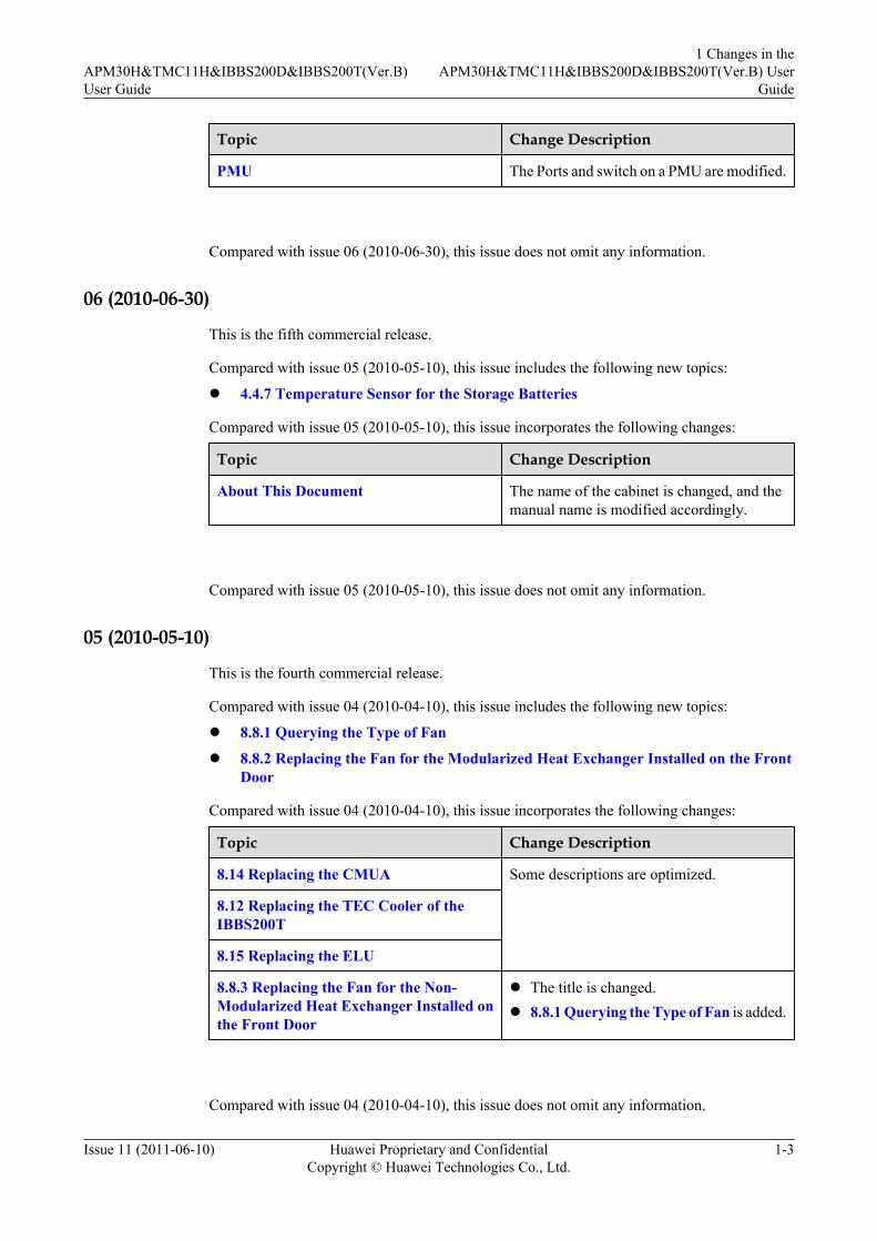
PMU The Ports and switch on a PMU are modified.
Compared with issue 06 (2010-06-30), this issue does not omit any information.
06 (2010-06-30)
This is the fifth commercial release.
Compared with issue 05 (2010-05-10), this issue includes the following new topics:
l 4.4.7 Temperature Sensor for the Storage Batteries
Compared with issue 05 (2010-05-10), this issue incorporates the following changes:
Topic Change Description
About This Document The name of the cabinet is changed, and themanual name is modified accordingly.
Compared with issue 05 (2010-05-10), this issue does not omit any information.
05 (2010-05-10)
This is the fourth commercial release.
Compared with issue 04 (2010-04-10), this issue includes the following new topics:
l 8.8.1 Querying the Type of Fan
l 8.8.2 Replacing the Fan for the Modularized Heat Exchanger Installed on the FrontDoor
Compared with issue 04 (2010-04-10), this issue incorporates the following changes:
Topic Change Description
8.14 Replacing the CMUA Some descriptions are optimized.
8.12 Replacing the TEC Cooler of theIBBS200T
8.15 Replacing the ELU
8.8.3 Replacing the Fan for the Non-Modularized Heat Exchanger Installed onthe Front Door
l The title is changed.l 8.8.1 Querying the Type of Fan is added.
Compared with issue 04 (2010-04-10), this issue does not omit any information.
APM30H&TMC11H&IBBS200D&IBBS200T(Ver.B)User Guide
1 Changes in theAPM30H&TMC11H&IBBS200D&IBBS200T(Ver.B) User
Guide
Issue 11 (2011-06-10) Huawei Proprietary and ConfidentialCopyright © Huawei Technologies Co., Ltd.
1-3

04 (2010-04-10)This is the third commercial release.
Compared with issue 03 (2009-12-30), this issue does not add any information.
Compared with issue 03 (2009-12-30), this issue incorporates the following changes:
Topic Change Description
PMU Some descriptions of the DIP switches areoptimized.
3.4.7 Heater (Optional) The technical specifications of the heater aremodified.
2.1 Functions of the APM30H, IBBS200T,IBBS200D, and TMC11H
The DC power distribution functions of theAPM30H are modified.
EPS Subrack The DC power distribution functions of theEPS subrack are modified.
8.6 Replacing the Fuse Some descriptions and figures are optimized.
8.11 Replacing the Batteries
Compared with issue 03 (2009-12-30), this issue does not omit any information.
03 (2009-12-30)This is the second commercial release.
Compared with issue 02 (2009-09-30), this issue does not add any information.
Compared with issue 02 (2009-09-30), this issue incorporates the following changes:
Topic Change Description
2.3.1 Electrical Specifications of theAPM30H and TMC11H
The known defects are cleared.
2.3.4 Environmental Requirements of theAPM30H, IBBS200T, IBBS200D, andTMC11H
7.2 Configuration of the SLPU The configuration principles of the SLPU aremodified.
Compared with issue 02 (2009-09-30), the following topics are deleted in this issue:l Replacing the Core of the Heat Exchanger
02 (2009-09-30)This is the first commercial release.
1 Changes in theAPM30H&TMC11H&IBBS200D&IBBS200T(Ver.B) UserGuide
APM30H&TMC11H&IBBS200D&IBBS200T(Ver.B)User Guide
1-4 Huawei Proprietary and ConfidentialCopyright © Huawei Technologies Co., Ltd.
Issue 11 (2011-06-10)

Compared with issue 01 (2009-08-14), no information is added.
Compared with issue 01 (2009-08-14), the known defects are cleared.
Compared with issue 01 (2009-08-14), no information is deleted.
01 (2009-08-14)This is the draft release.
APM30H&TMC11H&IBBS200D&IBBS200T(Ver.B)User Guide
1 Changes in theAPM30H&TMC11H&IBBS200D&IBBS200T(Ver.B) User
Guide
Issue 11 (2011-06-10) Huawei Proprietary and ConfidentialCopyright © Huawei Technologies Co., Ltd.
1-5


2 Overview of the APM30H Family
About This Chapter
The APM30H family consists of the APM30H, TMC11H, IBBS200T, and IBBS200D.
2.1 Functions of the APM30H, IBBS200T, IBBS200D, and TMC11HThe APM30H, IBBS200T, IBBS200D, and TMC11H provides auxiliary solutions to the outdoorapplications of Huawei wireless products. It supplies DC power to and provides backup powerfor distributed or separated base stations in outdoor scenarios. It can also be used for the outdoorapplications of the indoor BBUs and transmission equipment.
2.2 Application Scenarios of the APM30H FamilyThe APM30H family can work with the distributed or separated base stations, meeting therequirements in different scenarios.
2.3 Technical Specifications of the APM30H FamilyThe technical specifications of the APM30H family consist of the electrical specifications,engineering specifications, surge protection specifications, and specifications concerning theenvironmental requirements.
APM30H&TMC11H&IBBS200D&IBBS200T(Ver.B)User Guide 2 Overview of the APM30H Family
Issue 11 (2011-06-10) Huawei Proprietary and ConfidentialCopyright © Huawei Technologies Co., Ltd.
2-1

2.1 Functions of the APM30H, IBBS200T, IBBS200D, andTMC11H
The APM30H, IBBS200T, IBBS200D, and TMC11H provides auxiliary solutions to the outdoorapplications of Huawei wireless products. It supplies DC power to and provides backup powerfor distributed or separated base stations in outdoor scenarios. It can also be used for the outdoorapplications of the indoor BBUs and transmission equipment.
Functions of the APM30HTable 2-1 describes the functions of the APM30H.
Table 2-1 Functions of the APM30H
Function Description
Providing space for thecustomer equipment
The APM30H provides a 7 U space for the customer equipment.
Providing backuppower
The APM30H can connect to a single battery cabinet to support upto the 48 V 184 Ah battery pack or connect to two stacked batterypacks to support up to 48 V 368 Ah battery pack.
Providing built-inPSUs
l The PSU converts the input AC mains power into -48 V DCpower.
l The PSU is hot-swappable.
Providing a built-inPMU
l The PMU manages the PSUs and implements the batterycharging and discharging functions.
l The PMU provides RS485 communication ports and dry contactalarm ports for remote and unattended monitoring.
l The PMU supports the battery low voltage disconnect (BLVD)and load low voltage disconnect (LLVD) functions.
l The PMU is hot-swappable.
Supporting AC input The APM30H provides a built-in AC/DC power system, whichsupports single-phase 220 V AC, three-phase 220 V AC, and dual-live wire 110 V AC or 120 V AC.
Distributing AC power Through the EPS, the AC power is distributed into two AC outputs:l One output provides AC power for the SOU.l The other output is connected to the AC power distribution box
on the left of the cabinet. Through the power distribution, fourAC outputs are provided to the heater or heating film.
Distributing DC power For details, see Table 2-2.
2 Overview of the APM30H FamilyAPM30H&TMC11H&IBBS200D&IBBS200T(Ver.B)
User Guide
2-2 Huawei Proprietary and ConfidentialCopyright © Huawei Technologies Co., Ltd.
Issue 11 (2011-06-10)
Function Description
Providing surgeprotection for thepower supply andsignal ports
External surge protection modules for AC/DC power ports andsurge protection circuits for signal ports provide safe and reliablesurge protection and lightning protection.
Dissipating heat Heat dissipation of the APM30H is based on the heat exchangersystem that consists of a core and two air circulation fans. This caneffectively prevent dust from entering the cabinet. The APM30Hcan also work with the diesel generator.
Supporting thegrounding
The grounding busbar for the cabinet and the PGND cables for thecomponents are all connected to the grounding bar of the cabinet.
Reporting the cabinettype automatically
The type of the cabinet is automatically reported through the ELU.
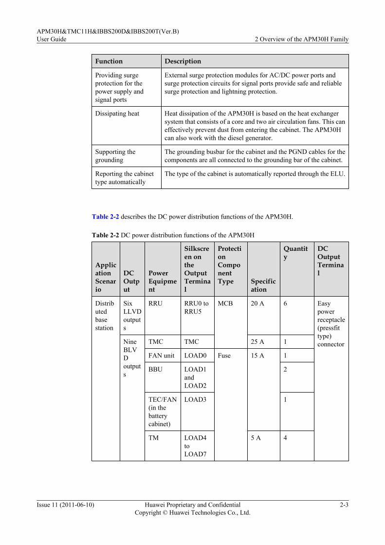
Table 2-2 describes the DC power distribution functions of the APM30H.
Table 2-2 DC power distribution functions of the APM30H
ApplicationScenario
DCOutput
PowerEquipment
Silkscreen ontheOutputTerminal
ProtectionComponentType Specific
ation
Quantity
DCOutputTerminal
Distributedbasestation
SixLLVDoutputs
RRU RRU0 toRRU5
MCB 20 A 6 Easypowerreceptacle(pressfittype)connectorNine
BLVDoutputs
TMC TMC 25 A 1
FAN unit LOAD0 Fuse 15 A 1
BBU LOAD1andLOAD2
2
TEC/FAN(in thebatterycabinet)
LOAD3 1
TM LOAD4toLOAD7
5 A 4
APM30H&TMC11H&IBBS200D&IBBS200T(Ver.B)User Guide 2 Overview of the APM30H Family
Issue 11 (2011-06-10) Huawei Proprietary and ConfidentialCopyright © Huawei Technologies Co., Ltd.
2-3

ApplicationScenario
DCOutput
PowerEquipment
Silkscreen ontheOutputTerminal
ProtectionComponentType Specific
ation
Quantity
DCOutputTerminal
Batterypowerbackup
BAT - MCB 100 A 1 Powerseries 120connector(grey)
Separatedmacrobasestation
TwoLLVDoutputs
RFC - MCB 80 A 2 Powerseries 120connector(blue)
NineBLVDoutputs
TMC TMC 25 A 1 Easypowerreceptacle(pressfittype)connector
FAN unit LOAD0 Fuse 15 A 1
BBU LOAD1andLOAD2
2
TEC/FAN(in thebatterycabinet)
LOAD3 1
TM LOAD4toLOAD7
5 A 4
Batterypowerbackup
BAT - MCB 100 A 1 Powerseries 120connector(grey)
Functions of the IBBS200TTable 2-3 describes the functions of the IBBS200T.
2 Overview of the APM30H FamilyAPM30H&TMC11H&IBBS200D&IBBS200T(Ver.B)
User Guide
2-4 Huawei Proprietary and ConfidentialCopyright © Huawei Technologies Co., Ltd.
Issue 11 (2011-06-10)

Table 2-3 Functions of the IBBS200T
Function Description
Providingbackup power
l When configured with 48 V 50 Ah batteries, the IBBS200T can provideDC backup power of 48 V 50 Ah or 48 V 100 Ah (by housing two batterypacks).
l When configured with 48 V 92 Ah batteries, the IBBS200T can provideDC backup power of 48 V 92 Ah or 48 V 184 Ah (by housing two batterypacks).
Reporting thecabinet typeautomatically
The type of the cabinet is automatically reported through the ELU.
Providing abuilt-in TECcooler
The TEC cooler enables the IBBS200T to adapt to high ambient temperatureand maintains a proper range of temperature for the cabinet.
Monitoring thealarm signalsin a centralizedway
The CMUA collects the alarm signals from the components such as the doorstatus sensor, temperature sensor of the battery, fan, and smoke sensor.Then, the CMUA transmits the alarm signals to the base station.
Functions of the IBBS200DTable 2-4 describes the functions of the IBBS200D.
Table 2-4 Functions of the IBBS200D
Function Description
Providingbackup power
l When configured with 48 V 50 Ah batteries, the IBBS200D can provideDC backup power of 48 V 50 Ah or 48 V 100 Ah (by housing two batterypacks).
l When configured with 48 V 92 Ah batteries, the IBBS200D can provideDC backup power of 48 V 92 Ah or 48 V 184 Ah (by housing two batterypacks).
Reporting thecabinet typeautomatically
The type of the cabinet is automatically reported through the ELU.
Providingbuilt-in fans
The fans in the cabinet speed up the circulation of the air inside and outsidethe cabinet and keep the temperature in the cabinet in a proper range
Monitoring thealarm signalsin a centralizedway
The CMUA collects the alarm signals from the components such as the doorstatus sensor, temperature sensor of the battery, fan, and smoke sensor.Then, the CMUA transmits the alarm signals to the base station.
APM30H&TMC11H&IBBS200D&IBBS200T(Ver.B)User Guide 2 Overview of the APM30H Family
Issue 11 (2011-06-10) Huawei Proprietary and ConfidentialCopyright © Huawei Technologies Co., Ltd.
2-5

Functions of the TMC11HTable 2-5 describes the functions of the TMC11H.
Table 2-5 Functions of the TMC11H
Function Description
Providing -48V DC power
The TMC11H is configured with a built-in DCDU-03 and performs thefollowing functions:l Supporting one -48 V DC inputl Providing nine -48 V DC outputs (LOAD0 to LOAD8)
Providingspace forcustomerequipment
l The TMC11H provides 11 U space for customer equipment.l If the heater is installed, the TMC11H provides 10 U space for customer
equipment.
Reportingalarms
The TMC11H provides the following two dry contact alarm ports for remoteand unmanned monitoring: One of the dry contact alarm ports is connectedto the door status sensor. An open circuit indicates that the connection isfaulty, whereas a closed circuit indicates that the connection is normal.
Reporting thecabinet typeautomatically
The type of the cabinet is automatically reported through the ELU.
2.2 Application Scenarios of the APM30H FamilyThe APM30H family can work with the distributed or separated base stations, meeting therequirements in different scenarios.
APM30H Working with a Distributed Base StationThe scenario in which the APM30H works with a distributed base station is as follows:
l The APM30H provides the 7 U space for the BBU and transmission equipment. The built-in power system of the APM30H supplies -48 V DC power to the distributed base stationand transmission equipment and charges the batteries in the battery cabinet.
l When the mains power is unavailable, the batteries in the IBBS200T supplies -48 V DCpower to the distribution base station and transmission equipment.
Figure 2-1 shows the scenario in which the APM30H stacked on the battery cabinet works witha distributed base station.
2 Overview of the APM30H FamilyAPM30H&TMC11H&IBBS200D&IBBS200T(Ver.B)
User Guide
2-6 Huawei Proprietary and ConfidentialCopyright © Huawei Technologies Co., Ltd.
Issue 11 (2011-06-10)
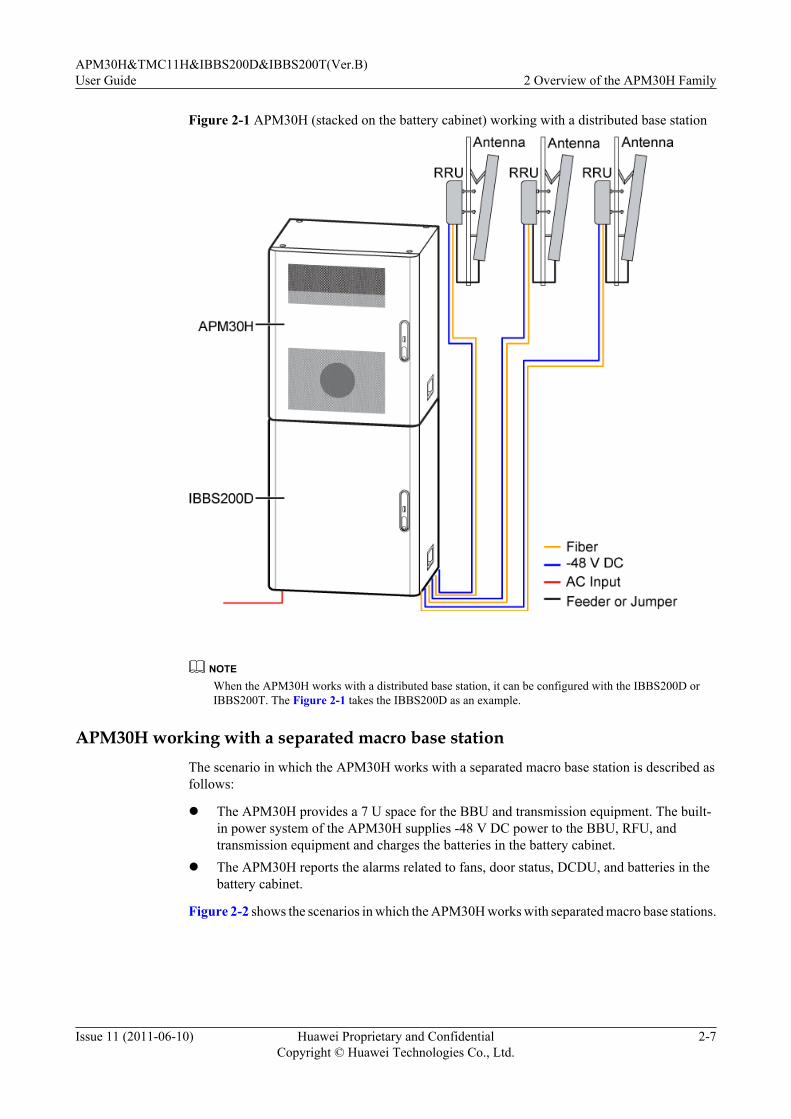
Figure 2-1 APM30H (stacked on the battery cabinet) working with a distributed base station
NOTEWhen the APM30H works with a distributed base station, it can be configured with the IBBS200D orIBBS200T. The Figure 2-1 takes the IBBS200D as an example.
APM30H working with a separated macro base stationThe scenario in which the APM30H works with a separated macro base station is described asfollows:
l The APM30H provides a 7 U space for the BBU and transmission equipment. The built-in power system of the APM30H supplies -48 V DC power to the BBU, RFU, andtransmission equipment and charges the batteries in the battery cabinet.
l The APM30H reports the alarms related to fans, door status, DCDU, and batteries in thebattery cabinet.
Figure 2-2 shows the scenarios in which the APM30H works with separated macro base stations.
APM30H&TMC11H&IBBS200D&IBBS200T(Ver.B)User Guide 2 Overview of the APM30H Family
Issue 11 (2011-06-10) Huawei Proprietary and ConfidentialCopyright © Huawei Technologies Co., Ltd.
2-7
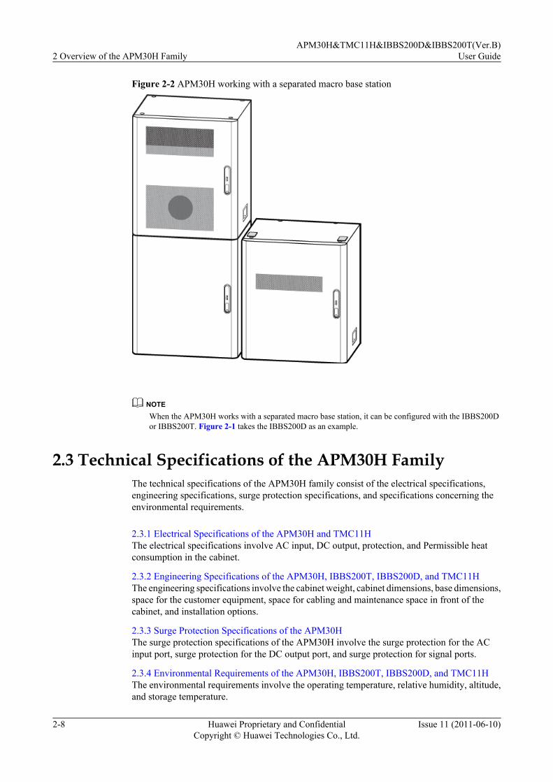
Figure 2-2 APM30H working with a separated macro base station
NOTEWhen the APM30H works with a separated macro base station, it can be configured with the IBBS200Dor IBBS200T. Figure 2-1 takes the IBBS200D as an example.
2.3 Technical Specifications of the APM30H FamilyThe technical specifications of the APM30H family consist of the electrical specifications,engineering specifications, surge protection specifications, and specifications concerning theenvironmental requirements.
2.3.1 Electrical Specifications of the APM30H and TMC11HThe electrical specifications involve AC input, DC output, protection, and Permissible heatconsumption in the cabinet.
2.3.2 Engineering Specifications of the APM30H, IBBS200T, IBBS200D, and TMC11HThe engineering specifications involve the cabinet weight, cabinet dimensions, base dimensions,space for the customer equipment, space for cabling and maintenance space in front of thecabinet, and installation options.
2.3.3 Surge Protection Specifications of the APM30HThe surge protection specifications of the APM30H involve the surge protection for the ACinput port, surge protection for the DC output port, and surge protection for signal ports.
2.3.4 Environmental Requirements of the APM30H, IBBS200T, IBBS200D, and TMC11HThe environmental requirements involve the operating temperature, relative humidity, altitude,and storage temperature.
2 Overview of the APM30H FamilyAPM30H&TMC11H&IBBS200D&IBBS200T(Ver.B)
User Guide
2-8 Huawei Proprietary and ConfidentialCopyright © Huawei Technologies Co., Ltd.
Issue 11 (2011-06-10)

2.3.1 Electrical Specifications of the APM30H and TMC11HThe electrical specifications involve AC input, DC output, protection, and Permissible heatconsumption in the cabinet.
Electrical Specifications of the APM30HTable 2-6 describes the electrical specifications of the APM30H.
Table 2-6 Electrical specifications of the APM30H
Item Specification
ACinput
Typicalinputvoltage
200 V AC to 240 V AC (single-phase 220 V AC)
200 V AC to 240 V AC or 346 V AC to 415 V AC (three-phase 220 VAC or 380 V AC)
100 V AC to 120 V AC or 200 V AC to 240 V AC (dual-live-wire 110V AC)
120 V AC to 127 V AC or 208 V AC to 220 V AC (dual-live-wire 120V AC)
Operatingvoltagerange
176 V AC to 290 V AC (single-phase 220 V AC)
176 V AC to 290 V AC or 304 V AC to 500 V AC (three-phase 220 VAC)
90 V AC to 135 V AC or 180 V AC to 270 V AC (dual-live-wire 110 VAC)
105 V AC to 150 V AC or 176 V AC to 260 V AC (dual-live-wire 120V AC)
Frequency of theinputvoltage
50 Hz or 60 Hz
Maximum inputcurrent
16 A (three-phase 220 V AC or 380 V AC)
40 A (dual-live-wire 110 V AC, dual-live-wire 120 V AC, or single-phase220 V AC)
Inputmode
l Three-phase 220 V AC or 380 V ACl Dual-live-wire 110 V ACl Dual-live-wire 120 V ACl Single-phase 220 V AC
APM30H&TMC11H&IBBS200D&IBBS200T(Ver.B)User Guide 2 Overview of the APM30H Family
Issue 11 (2011-06-10) Huawei Proprietary and ConfidentialCopyright © Huawei Technologies Co., Ltd.
2-9
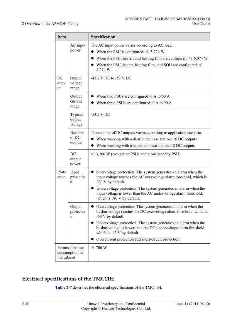
Item Specification
AC inputpower
The AC input power varies according to AC load.l When the PSU is configured: ≤ 5,274 Wl When the PSU, heater, and heating film are configured: ≤ 6,074 Wl When the PSU, heater, heating film, and SOU are configured: ≤
8,274 W
DCoutput
Outputvoltagerange
-43.2 V DC to -57 V DC
Outputcurrentrange
l When two PSUs are configured: 0 A to 60 Al When three PSUs are configured: 0 A to 90 A
Typicaloutputvoltage
-53.5 V DC
Numberof DCoutputs
The number of DC outputs varies according to application scenario.l When working with a distributed base station: 16 DC outputsl When working with a separated base station: 12 DC outputs
DCoutputpower
≤ 3,200 W (two active PSUs and + one standby PSU)
Protection
Inputprotection
l Overvoltage protection: The system generates an alarm when theinput voltage reaches the AC overvoltage alarm threshold, which is280 V by default.
l Undervoltage protection: The system generates an alarm when theinput voltage is lower than the AC undervoltage alarm threshold,which is 180 V by default.
Outputprotection
l Overvoltage protection: The system generates an alarm when thebusbar voltage reaches the DC overvoltage alarm threshold, which is-58 V by default.
l Undervoltage protection: The system generates an alarm when thebusbar voltage is lower than the DC undervoltage alarm threshold,which is -45 V by default.
l Overcurrent protection and short-circuit protection
Permissible heatconsumption inthe cabinet
≤ 700 W
Electrical specifications of the TMC11HTable 2-7 describes the electrical specifications of the TMC11H.
2 Overview of the APM30H FamilyAPM30H&TMC11H&IBBS200D&IBBS200T(Ver.B)
User Guide
2-10 Huawei Proprietary and ConfidentialCopyright © Huawei Technologies Co., Ltd.
Issue 11 (2011-06-10)
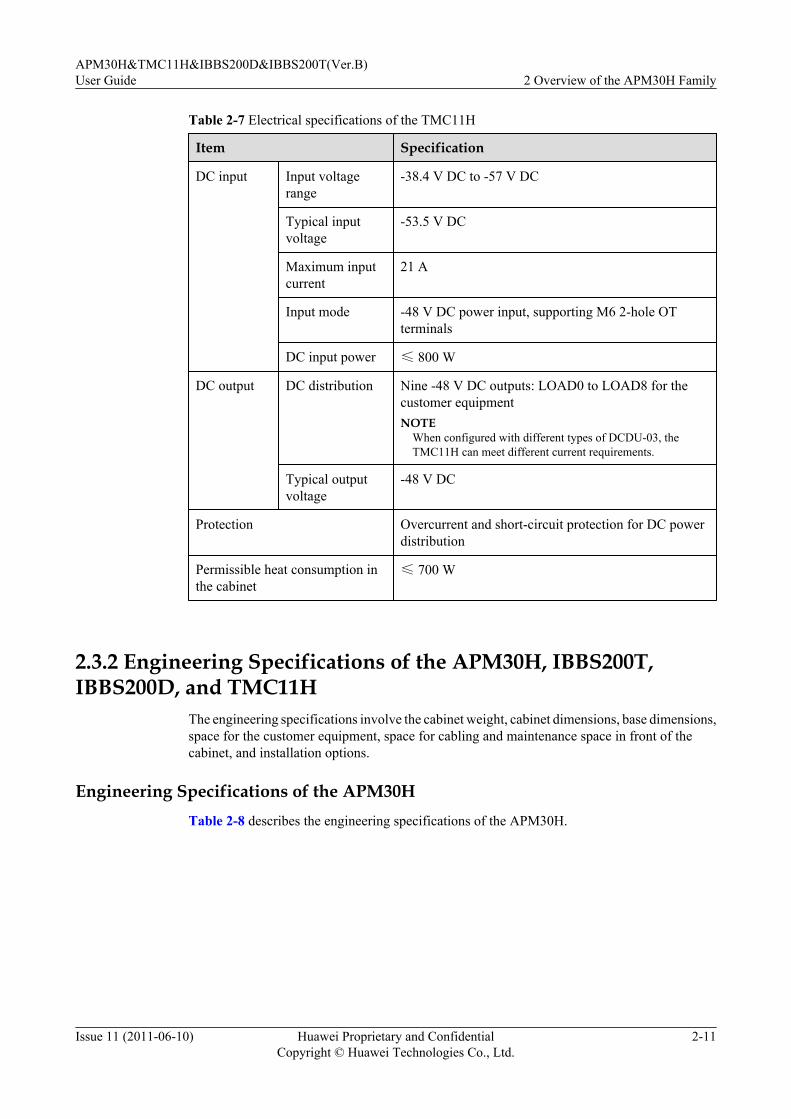
Table 2-7 Electrical specifications of the TMC11H
Item Specification
DC input Input voltagerange
-38.4 V DC to -57 V DC
Typical inputvoltage
-53.5 V DC
Maximum inputcurrent
21 A
Input mode -48 V DC power input, supporting M6 2-hole OTterminals
DC input power ≤ 800 W
DC output DC distribution Nine -48 V DC outputs: LOAD0 to LOAD8 for thecustomer equipmentNOTE
When configured with different types of DCDU-03, theTMC11H can meet different current requirements.
Typical outputvoltage
-48 V DC
Protection Overcurrent and short-circuit protection for DC powerdistribution
Permissible heat consumption inthe cabinet
≤ 700 W
2.3.2 Engineering Specifications of the APM30H, IBBS200T,IBBS200D, and TMC11H
The engineering specifications involve the cabinet weight, cabinet dimensions, base dimensions,space for the customer equipment, space for cabling and maintenance space in front of thecabinet, and installation options.
Engineering Specifications of the APM30HTable 2-8 describes the engineering specifications of the APM30H.
APM30H&TMC11H&IBBS200D&IBBS200T(Ver.B)User Guide 2 Overview of the APM30H Family
Issue 11 (2011-06-10) Huawei Proprietary and ConfidentialCopyright © Huawei Technologies Co., Ltd.
2-11

Table 2-8 Engineering specifications of the APM30H
Item Specification Remarks
Weight ≤ 72 kg Total weight of the equipmentl Including the cabinet frame, inner air
circulation fan, outer air circulation fan,core of the heart exchanger,EPS4890B-4830A, and cables
l Excluding the BBU, transmissionequipment of the customer, PMU, andPSU
≤ 91 kg Weight of the cabinet in full configurationl Including the equipment, one PMU, three
PSUs, and one BBUl Excluding the transmission equipment of
the customer
Dimensions of thecabinet (width xheight x depth)
600 mm x 700 mm x480 mm
The base is not included.
Dimensions of thebase (width x heightx depth)
600 mm x 200 mm x434 mm
-
Space for thecustomer equipment(width x height xdepth)
19-inch x 7 U x 310mm
The depth is measured from 30 mm in frontof the column to the back of the cabinet, andthe total measurement of the depth is 310 mm.
Space for cablingand maintenancespace in front of thecabinet
70 mm -
Installation option The APM30H can beinstalled on theground, on a wall, oron a pole, or stackedwith the RFC or theIBBS200D/IBBS200T.
When installed in stack mode, the APM30Hshould be placed on the RFC or theIBBS200D/IBBS200T.
Engineering Specifications of the IBBS200TTable 2-9 describes the engineering specifications of the IBBS200T.
2 Overview of the APM30H FamilyAPM30H&TMC11H&IBBS200D&IBBS200T(Ver.B)
User Guide
2-12 Huawei Proprietary and ConfidentialCopyright © Huawei Technologies Co., Ltd.
Issue 11 (2011-06-10)

Table 2-9 Engineering specifications of the IBBS200T
Item Specification Remarks
Cabinet weight ≤ 70 kg Built-in batteries are notconfigured.
Battery weight Supporting front maintenance of48 V 50 Ah or 48 V 92 Ahbatteriesl A single 12 V 50 Ah battery:
21.5 kgl A single 12 V 92 Ah battery:
33.5 kgNOTE
The batteries of differentmanufacturers may have differentweights. The following descriptionis based on common batteries.
Two 48 V 92 Ah battery packscan be connected in parallel toprovide 48 V 184 Ah backuppower.
Dimensions of thecabinet (width xheight x depth)
600 mm x 700 mm x 480 mm Excluding the 206 mm that isstretched out of the cabinet on thefront door.
Base dimensions(width x height xdepth)
600 mm x 200 mm x 434 mm -
Installation option The IBBS200T can be installedon the ground or stacked with theTMC11H or APM30H.
When installed in stack mode, theIBBS200T should be placedbelow the TMC11H or APM30H.
Engineering Specifications of the IBBS200DTable 2-10 describes the engineering specifications of the IBBS200D.
Table 2-10 Engineering specifications of the IBBS200D
Item Specification Remarks
Cabinet weight ≤ 50 kg Built-in batteries are notconfigured.
APM30H&TMC11H&IBBS200D&IBBS200T(Ver.B)User Guide 2 Overview of the APM30H Family
Issue 11 (2011-06-10) Huawei Proprietary and ConfidentialCopyright © Huawei Technologies Co., Ltd.
2-13

Item Specification Remarks
Battery weight Supporting front maintenance of48 V 50 Ah or 48 V 92 Ahbatteriesl A single 12 V 50 Ah battery:
21.5 kgl A single 12 V 92 Ah battery:
33.5 kgNOTE
The batteries of differentmanufacturers may have differentweights. The following descriptionis based on common batteries.
Two 48 V 92 Ah battery packscan be connected in parallel toprovide 48 V 184 Ah backuppower.
Dimensions of thecabinet (width xheight x depth)
600 mm x 700 mm x 480 mm -
Base dimensions(width x height xdepth)
600 mm x 200 mm x 434 mm
Installation option The IBBS200D can be installedon the ground or stacked with theRFC or APM30H.
When installed in stack mode, theIBBS200D should be placedbelow the RFC or APM30H.
Engineering Specifications of the TMC11HTable 2-11 describes the engineering specifications of the TMC11H.
Table 2-11 Engineering specifications of the TMC11H
Item Specification Remarks
Weight ≤ 57 kg Total weight of the equipmentl Including the cabinet frame, fan box,
and core of the heart exchangerl Excluding the BBU and transmission
equipment of the customer
Dimensions of thecabinet (width xheight x depth)
600 mm x 700 mm x 480mm
The appearance and base of the TMC11Hare the same as those of the APM30H.
Base dimensions(width x height xdepth)
600 mm x 200 mm x 434mm
2 Overview of the APM30H FamilyAPM30H&TMC11H&IBBS200D&IBBS200T(Ver.B)
User Guide
2-14 Huawei Proprietary and ConfidentialCopyright © Huawei Technologies Co., Ltd.
Issue 11 (2011-06-10)
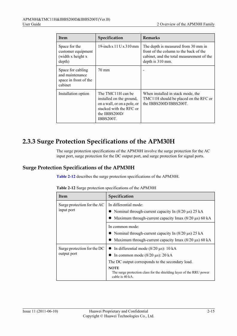
Item Specification Remarks
Space for thecustomer equipment(width x height xdepth)
19-inch x 11 U x 310 mm The depth is measured from 30 mm infront of the column to the back of thecabinet, and the total measurement of thedepth is 310 mm.
Space for cablingand maintenancespace in front of thecabinet
70 mm -
Installation option The TMC11H can beinstalled on the ground,on a wall, or on a pole, orstacked with the RFC orthe IBBS200D/IBBS200T.
When installed in stack mode, theTMC11H should be placed on the RFC orthe IBBS200D/IBBS200T.
2.3.3 Surge Protection Specifications of the APM30HThe surge protection specifications of the APM30H involve the surge protection for the ACinput port, surge protection for the DC output port, and surge protection for signal ports.
Surge Protection Specifications of the APM30HTable 2-12 describes the surge protection specifications of the APM30H.
Table 2-12 Surge protection specifications of the APM30H
Item Specification
Surge protection for the ACinput port
In differential mode:l Nominal through-current capacity In (8/20 µs) 25 kAl Maximum through-current capacity Imax (8/20 µs) 60 kA
In common mode:l Nominal through-current capacity In (8/20 µs) 25 kAl Maximum through-current capacity Imax (8/20 µs) 60 kA
Surge protection for the DCoutput port
l In differential mode (8/20 µs): 10 kAl In common mode (8/20 µs): 20 kAThe DC output corresponds to the secondary load.NOTE
The surge protection class for the shielding layer of the RRU powercable is 40 kA.
APM30H&TMC11H&IBBS200D&IBBS200T(Ver.B)User Guide 2 Overview of the APM30H Family
Issue 11 (2011-06-10) Huawei Proprietary and ConfidentialCopyright © Huawei Technologies Co., Ltd.
2-15
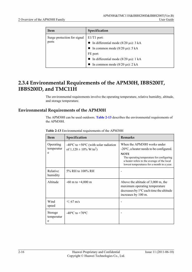
Item Specification
Surge protection for signalports
E1/T1 port:l In differential mode (8/20 µs): 3 kAl In common mode (8/20 µs): 5 kAFE port:l In differential mode (8/20 µs): 1 kAl In common mode (8/20 µs): 2 kA
2.3.4 Environmental Requirements of the APM30H, IBBS200T,IBBS200D, and TMC11H
The environmental requirements involve the operating temperature, relative humidity, altitude,and storage temperature.
Environmental Requirements of the APM30HThe APM30H can be used outdoors. Table 2-13 describes the environmental requirements ofthe APM30H.
Table 2-13 Environmental requirements of the APM30H
Item Specification Remarks
Operatingtemperature
-40oC to +50oC (with solar radiationof 1,120 ± 10% W/m2)
When the APM30H works under-20oC, a heater needs to be configured.NOTE
The operating temperature for configuringa heater refers to the average of the locallowest temperatures for a month in a year.
Relativehumidity
5% RH to 100% RH -
Altitude -60 m to +4,000 m Above the altitude of 3,000 m, themaximum operating temperaturedecreases by 1oC each time the altitudeincreases by 100 m.
Windspeed
≤ 67 m/s -
Storagetemperature
-40oC to +70oC -
2 Overview of the APM30H FamilyAPM30H&TMC11H&IBBS200D&IBBS200T(Ver.B)
User Guide
2-16 Huawei Proprietary and ConfidentialCopyright © Huawei Technologies Co., Ltd.
Issue 11 (2011-06-10)

Item Specification Remarks
Dustproofandwaterproofspecification
IP55 -
Noise - Complying with the ETS 300 753 4.1Estandard (in a rural scenario)
Environmental Requirements of the IBBS200TThe IBBS200T can be used outdoors. Table 2-14 describes the environmental requirements ofthe IBBS200T.
Table 2-14 Environmental requirements of the IBBS200T
Item Specification Remarks
Operatingtemperature
-20oC to +50oC (with solar radiationof not more than 1,120 ± 10% W/m2)
-
Relativehumidity
5% RH to 100% RH -
Altitude -60 m to +4,000 m Above the altitude of 3,000 m, themaximum operating temperaturedecreases by 1oC each time the altitudeincreases by 100 m.
Windspeed
≤ 67 m/s -
Storagetemperature
-40oC to +70oC -
Dustproofandwaterproofspecification
IP55 -
Noise - Complying with the ETS 300 753 4.1Estandard (in an urban scenario)
Environmental Requirements of the IBBS200DThe IBBS200D can be used outdoors. Table 2-15 describes the environmental requirements ofthe IBBS200D.
APM30H&TMC11H&IBBS200D&IBBS200T(Ver.B)User Guide 2 Overview of the APM30H Family
Issue 11 (2011-06-10) Huawei Proprietary and ConfidentialCopyright © Huawei Technologies Co., Ltd.
2-17

Table 2-15 Environmental requirements of the IBBS200D
Item Specification Remarks
Operatingtemperature
-40oC to +45oC (with solar radiationof not more than 1,120 ± 10% W/m2)
When the IBBS200D works under-200C, a heater film needs to beconfigured.NOTE
The operating temperature for configuringa heating film refers to the average of thelocal lowest temperatures recorded for amonth in a year.
Relativehumidity
5% RH to 100% RH -
Altitude -60 m to +4,000 m Above the altitude of 3,000 m, themaximum operating temperaturedecreases by 1oC each time the altitudeincreases by 100 m.
Windspeed
≤ 67 m/s -
Storagetemperature
-40oC to +70oC -
Dustproofandwaterproofspecification
IP35 -
Noise - Complying with the ETS 300 753 4.1Estandard (in a rural scenario)
Environmental Requirements of the TMC11HThe TMC11H can be used outdoors. The environmental requirements of the TMC11H are thesame as those of the APM30H. For details, see Table 2-13.
2 Overview of the APM30H FamilyAPM30H&TMC11H&IBBS200D&IBBS200T(Ver.B)
User Guide
2-18 Huawei Proprietary and ConfidentialCopyright © Huawei Technologies Co., Ltd.
Issue 11 (2011-06-10)

3 Overview of the APM30H
About This Chapter
This describes the exterior, structure, and components of the APM30H.
3.1 Exterior of the APM30HThe APM30H is elegantly designed. It is small in size and easy to transport.
3.2 Structure of the APM30HThe APM30H has a highly integrated and modular structure design. Thus, the cabinet is easy tooperate and maintain.
3.3 Cable Connections of the APM30HThe cables of the APM30H are power cables and signal cables.
3.4 APM30H ComponentsThe components of the APM30H consist of the fan box, power system (AC/DC), power system(DC/DC), core of the heat exchanger, junction box, Electronic Label Unit (ELU), heater, andService Outlet Unit (SOU). The heater and the SOU are optional.
3.5 APM30H CablesThe APM30H cables consist of the PGND cable, input power cable, environment monitoringsignal cable, and monitoring signal cable for the PMU.
APM30H&TMC11H&IBBS200D&IBBS200T(Ver.B)User Guide 3 Overview of the APM30H
Issue 11 (2011-06-10) Huawei Proprietary and ConfidentialCopyright © Huawei Technologies Co., Ltd.
3-1

3.1 Exterior of the APM30HThe APM30H is elegantly designed. It is small in size and easy to transport.
Figure 3-1 shows exterior of the APM30H.
Figure 3-1 Exterior of the APM30H
3.2 Structure of the APM30HThe APM30H has a highly integrated and modular structure design. Thus, the cabinet is easy tooperate and maintain.
Figure 3-2 shows the internal structure of the APM30H.
3 Overview of the APM30HAPM30H&TMC11H&IBBS200D&IBBS200T(Ver.B)
User Guide
3-2 Huawei Proprietary and ConfidentialCopyright © Huawei Technologies Co., Ltd.
Issue 11 (2011-06-10)

Figure 3-2 Internal structure of the APM30H
(1) HPMI (2) Inner air circulation fan (3) CMUA
(4) PSU (5) Door status sensor (6) ELU
(7) EPS (8) Outer air circulation fan (9) Heat exchanger
(10) Junction box (11)PMU -
As shown in the preceding picture, the APM30H provides space as follows:l If the heater or the SOU is not installed, the APM30H provides a 7 U space for the customer
equipment.l If the heater or the SOU is installed, the APM30H provides a 6 U space for the customer
equipment.l The APM30H provides a 1 U space at the top for operation and maintenance of the fan box.
3.3 Cable Connections of the APM30HThe cables of the APM30H are power cables and signal cables.
Cable Connections of the APM30H Working with a Distributed Base StationFigure 3-3 shows the cable connections of the APM30H working with a distributed base station.
APM30H&TMC11H&IBBS200D&IBBS200T(Ver.B)User Guide 3 Overview of the APM30H
Issue 11 (2011-06-10) Huawei Proprietary and ConfidentialCopyright © Huawei Technologies Co., Ltd.
3-3
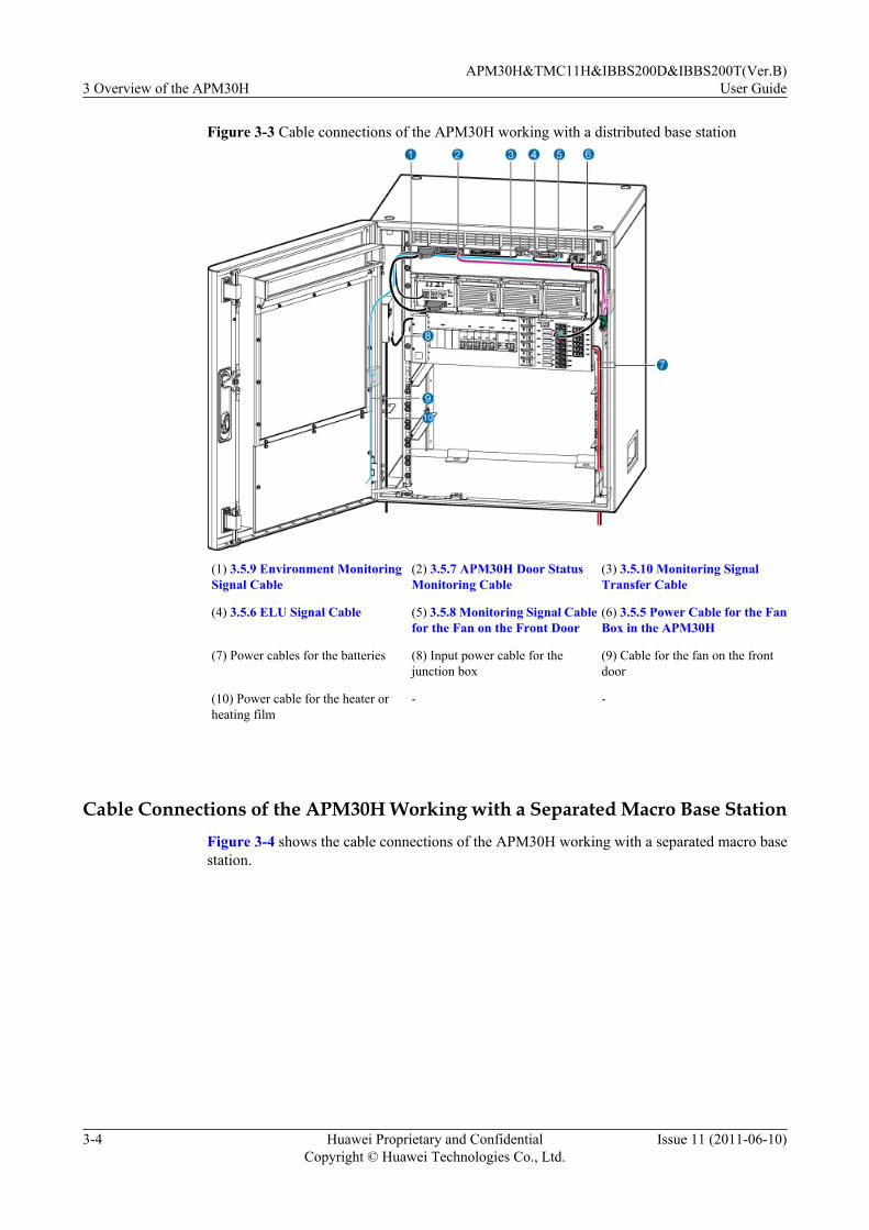
Figure 3-3 Cable connections of the APM30H working with a distributed base station
(1) 3.5.9 Environment MonitoringSignal Cable
(2) 3.5.7 APM30H Door StatusMonitoring Cable
(3) 3.5.10 Monitoring SignalTransfer Cable
(4) 3.5.6 ELU Signal Cable (5) 3.5.8 Monitoring Signal Cablefor the Fan on the Front Door
(6) 3.5.5 Power Cable for the FanBox in the APM30H
(7) Power cables for the batteries (8) Input power cable for thejunction box
(9) Cable for the fan on the frontdoor
(10) Power cable for the heater orheating film
- -
Cable Connections of the APM30H Working with a Separated Macro Base StationFigure 3-4 shows the cable connections of the APM30H working with a separated macro basestation.
3 Overview of the APM30HAPM30H&TMC11H&IBBS200D&IBBS200T(Ver.B)
User Guide
3-4 Huawei Proprietary and ConfidentialCopyright © Huawei Technologies Co., Ltd.
Issue 11 (2011-06-10)

Figure 3-4 Cable connections of the APM30H working with a separated macro base station
(1) 3.5.9 Environment MonitoringSignal Cable
(2) 3.5.7 APM30H Door StatusMonitoring Cable
(3) 3.5.10 Monitoring SignalTransfer Cable
(4) 3.5.6 ELU Signal Cable (5) 3.5.8 Monitoring Signal Cablefor the Fan on the Front Door
(6) 3.5.5 Power Cable for the FanBox in the APM30H
(7) Power cables for RFC1 (8) Power cables for RFC2 (9) Power cables for the batteries
(10) Input power cable for thejunction box
(11) Cable for the fan on the frontdoor
(12) Power cable for the heater orheating film
3.4 APM30H ComponentsThe components of the APM30H consist of the fan box, power system (AC/DC), power system(DC/DC), core of the heat exchanger, junction box, Electronic Label Unit (ELU), heater, andService Outlet Unit (SOU). The heater and the SOU are optional.
3.4.1 Fan BoxThe fan box consists of the fan subrack, fans, HPMI, and CMUA.
3.4.2 AC/DC Power SystemThe AC/DC power system consists of the EPS, PMU, and PSU (AC/DC).
3.4.3 Power Equipment (DC/DC)The power equipment (DC/DC) converts +24 V DC power into -48 V DC power.
3.4.4 Core of the Heat Exchanger
APM30H&TMC11H&IBBS200D&IBBS200T(Ver.B)User Guide 3 Overview of the APM30H
Issue 11 (2011-06-10) Huawei Proprietary and ConfidentialCopyright © Huawei Technologies Co., Ltd.
3-5
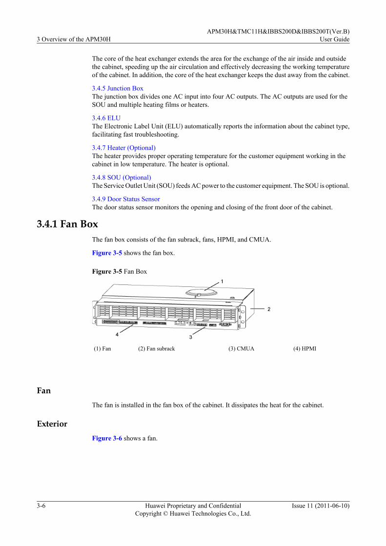
The core of the heat exchanger extends the area for the exchange of the air inside and outsidethe cabinet, speeding up the air circulation and effectively decreasing the working temperatureof the cabinet. In addition, the core of the heat exchanger keeps the dust away from the cabinet.
3.4.5 Junction BoxThe junction box divides one AC input into four AC outputs. The AC outputs are used for theSOU and multiple heating films or heaters.
3.4.6 ELUThe Electronic Label Unit (ELU) automatically reports the information about the cabinet type,facilitating fast troubleshooting.
3.4.7 Heater (Optional)The heater provides proper operating temperature for the customer equipment working in thecabinet in low temperature. The heater is optional.
3.4.8 SOU (Optional)The Service Outlet Unit (SOU) feeds AC power to the customer equipment. The SOU is optional.
3.4.9 Door Status SensorThe door status sensor monitors the opening and closing of the front door of the cabinet.
3.4.1 Fan BoxThe fan box consists of the fan subrack, fans, HPMI, and CMUA.
Figure 3-5 shows the fan box.
Figure 3-5 Fan Box
(1) Fan (2) Fan subrack (3) CMUA (4) HPMI
FanThe fan is installed in the fan box of the cabinet. It dissipates the heat for the cabinet.
ExteriorFigure 3-6 shows a fan.
3 Overview of the APM30HAPM30H&TMC11H&IBBS200D&IBBS200T(Ver.B)
User Guide
3-6 Huawei Proprietary and ConfidentialCopyright © Huawei Technologies Co., Ltd.
Issue 11 (2011-06-10)

Figure 3-6 Fan
Technical SpecificationsTable 3-1 describes the technical specifications of the fan.
Table 3-1 Technical specifications of the fan
Item Specification
Dimensions (Diameter x Height) 175 mm x 69 mm
Length of the leadNOTE
The lead is delivered with the fan and is used forpower input and monitoring.
450 mm
Definition of pins 1 to 4 of the lead l Pin 1: red, connected to the positive poleof the power supply
l Pin 2: yellow, connected to the input of thespeed-adjusting signals
l Pin 3: blue, connected to the output of thealarm or speed signals
l Pin 4: black, connected to the negativepole of the power supply
NOTEThe colors of the cables of the fans vary accordingto the manufacturer.
Rated voltage -48 V
Operating voltage range -36 V to -57 V
Rated current 0.52 A
Maximum current 0.77 A
Rated power 24.96 W
APM30H&TMC11H&IBBS200D&IBBS200T(Ver.B)User Guide 3 Overview of the APM30H
Issue 11 (2011-06-10) Huawei Proprietary and ConfidentialCopyright © Huawei Technologies Co., Ltd.
3-7
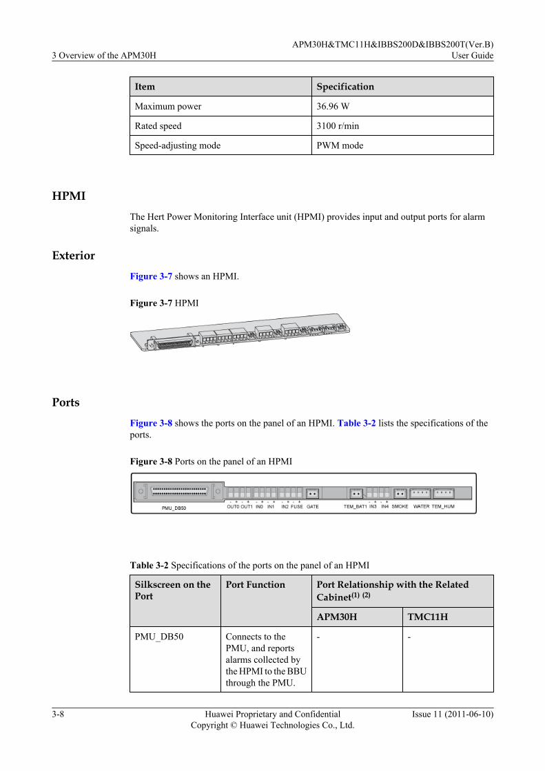
Item Specification
Maximum power 36.96 W
Rated speed 3100 r/min
Speed-adjusting mode PWM mode
HPMIThe Hert Power Monitoring Interface unit (HPMI) provides input and output ports for alarmsignals.
ExteriorFigure 3-7 shows an HPMI.
Figure 3-7 HPMI
PortsFigure 3-8 shows the ports on the panel of an HPMI. Table 3-2 lists the specifications of theports.
Figure 3-8 Ports on the panel of an HPMI
Table 3-2 Specifications of the ports on the panel of an HPMI
Silkscreen on thePort
Port Function Port Relationship with the RelatedCabinet(1) (2)
APM30H TMC11H
PMU_DB50 Connects to thePMU, and reportsalarms collected bythe HPMI to the BBUthrough the PMU.
- -
3 Overview of the APM30HAPM30H&TMC11H&IBBS200D&IBBS200T(Ver.B)
User Guide
3-8 Huawei Proprietary and ConfidentialCopyright © Huawei Technologies Co., Ltd.
Issue 11 (2011-06-10)
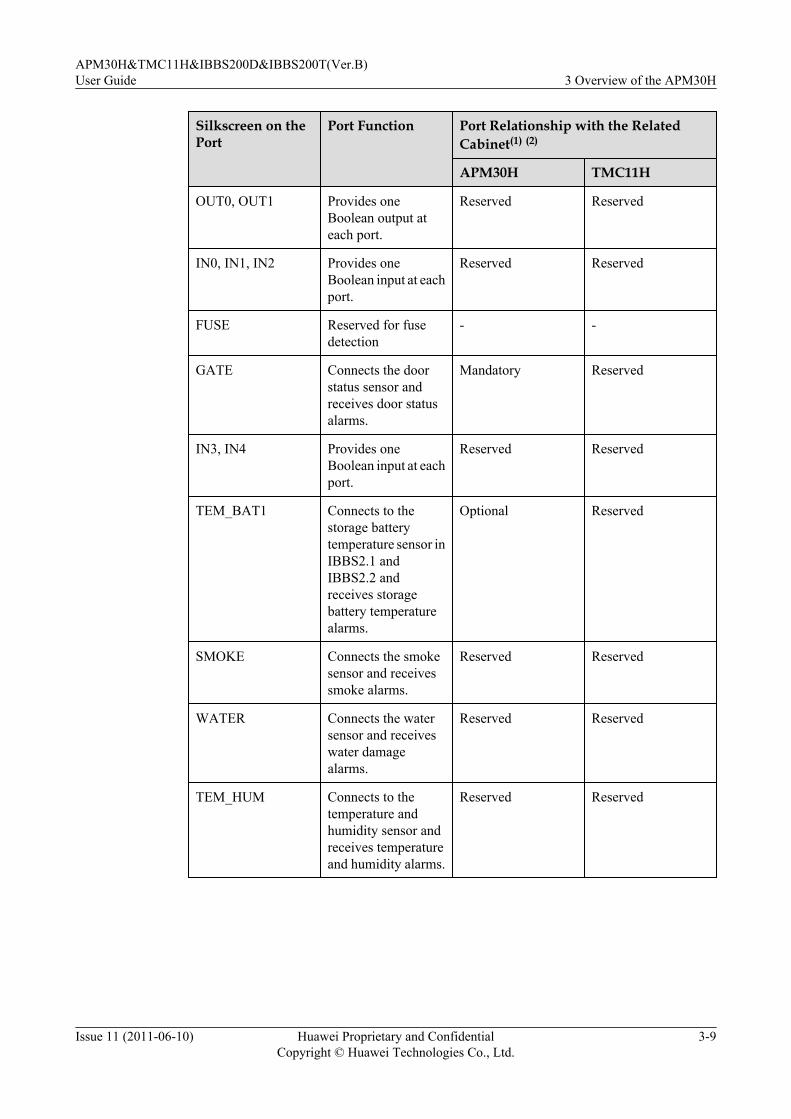
Silkscreen on thePort
Port Function Port Relationship with the RelatedCabinet(1) (2)
APM30H TMC11H
OUT0, OUT1 Provides oneBoolean output ateach port.
Reserved Reserved
IN0, IN1, IN2 Provides oneBoolean input at eachport.
Reserved Reserved
FUSE Reserved for fusedetection
- -
GATE Connects the doorstatus sensor andreceives door statusalarms.
Mandatory Reserved
IN3, IN4 Provides oneBoolean input at eachport.
Reserved Reserved
TEM_BAT1 Connects to thestorage batterytemperature sensor inIBBS2.1 andIBBS2.2 andreceives storagebattery temperaturealarms.
Optional Reserved
SMOKE Connects the smokesensor and receivessmoke alarms.
Reserved Reserved
WATER Connects the watersensor and receiveswater damagealarms.
Reserved Reserved
TEM_HUM Connects to thetemperature andhumidity sensor andreceives temperatureand humidity alarms.
Reserved Reserved
APM30H&TMC11H&IBBS200D&IBBS200T(Ver.B)User Guide 3 Overview of the APM30H
Issue 11 (2011-06-10) Huawei Proprietary and ConfidentialCopyright © Huawei Technologies Co., Ltd.
3-9

NOTE
(1) Mandatory monitoring devices are installed in the cabinet before delivery, and related monitoring signalcables are connected before delivery. Optional devices are configured based on customer requirements,and related cables must be connected on site. For details about how to connect the cables, see BTS3900AInstallation Guide.
(2) For details about the positions of devices monitored by the HPMI, see Structure of the BTS3900ACabinet.
CMUAThis section describes the central monitoring unit type A (CMUA).
FunctionsThe CMUA has the following functions:
l Adjusts and controls temperature of the cabinet in different temperature control modes.l Reserves a port for three Boolean inputs and detects Boolean alarms in the cabinet. The
remote detection, however, is not supported.l Provides a port for the RJ45 connector to enable electronic label and cabinet type detection.
ExteriorFigure 3-9 shows a CMUA.
Figure 3-9 CMUA
PortsFigure 3-10 shows the ports on the CMUA, and Table 3-3 describes the ports.
3 Overview of the APM30HAPM30H&TMC11H&IBBS200D&IBBS200T(Ver.B)
User Guide
3-10 Huawei Proprietary and ConfidentialCopyright © Huawei Technologies Co., Ltd.
Issue 11 (2011-06-10)

Figure 3-10 Ports on a CMUA (plan view)
Table 3-3 Ports on a CMUA
Silkscreen on thePort
Port Function Port Relationship with the RelatedCabinet(1)(2)
APM30H
TMC11H
RFC IBBS200D
IBBS200T
l TEM(in theRFC)
l TEM_BAT(in theIBBS200D/IBBS200T)
l In the RFC: connects tothe temperature sensor atthe air inlet of the cabinetand receives temperaturealarms.
l In the IBBS200D/IBBS200T: connects tothe storage batterytemperature sensor in theIBBS200D/IBBS200Tand receives storagebattery temperaturealarms.
Reserved
Reserved
Mandatory
Mandatory
Mandatory
COM_OUT
Communication port forlower-level cascadingl Connecting to the PMU
(in an APM30H)l Connecting to the lower-
level CMUA (in an RFC,TMC11H, IBBS200D, orIBBS200T)
- - - - -
APM30H&TMC11H&IBBS200D&IBBS200T(Ver.B)User Guide 3 Overview of the APM30H
Issue 11 (2011-06-10) Huawei Proprietary and ConfidentialCopyright © Huawei Technologies Co., Ltd.
3-11

Silkscreen on thePort
Port Function Port Relationship with the RelatedCabinet(1)(2)
APM30H
TMC11H
RFC IBBS200D
IBBS200T
COM_IN Communication port forupper-level cascadingl Connecting to the BBU
(in an APM30H)l Connecting to the BBU or
upper-level CMUA (in anRFC or TMC11H)
l Connecting to the PMU orupper-level CMUA (in anIBBS200D or IBBS200T)
- - - - -
ELU Connects to the ElectronicLabel Unit (ELU) andreceives ELU-related alarms.
Mandatory
Mandatory
Mandatory
Mandatory
Mandatory
GATE Connects the door statussensor and receives doorstatus alarms.
Reserved
Mandatory
Mandatory
Mandatory
Mandatory
IN0, IN1,IN2
Provides one Boolean input ateach port.
Reserved
Reserved
Reserved
Reserved
Reserved
SMOKE Connects to the smoke sensorand receives smoke alarms.
Reserved
Reserved
Reserved
Reserved
Reserved
FAN_EXT
Connects to the outer aircirculation fan on the cabinetand receives alarms related tothe outer air circulation fan.
Mandatory
Mandatory
Reserved
Reserved
Reserved
TECcooler
Connects to the TEC coolerand receives alarms related tothe TEC cooler.
Reserved
Reserved
Reserved
Reserved
Mandatory
3 Overview of the APM30HAPM30H&TMC11H&IBBS200D&IBBS200T(Ver.B)
User Guide
3-12 Huawei Proprietary and ConfidentialCopyright © Huawei Technologies Co., Ltd.
Issue 11 (2011-06-10)

Silkscreen on thePort
Port Function Port Relationship with the RelatedCabinet(1)(2)
APM30H
TMC11H
RFC IBBS200D
IBBS200T
l FAN1(in theAPM30H,TMC11H,RFC,orIBBS200D)
l FAN_EXT(in theIBBS200T)
l In the TMC11H orTMC11H: connects to thefan in the fan box.
l In the RFC or IBBS200D:connects to the fan on theright of the fan box.
l In the IBBS200T:connects to the outer aircirculation fan on the TECcooler and receives fan-related alarms fromcabinets.
Mandatory
Mandatory
Mandatory
Mandatory
Mandatory
l FAN2(in theRFCandIBBS200D)
l FAN_INT (intheIBBS200T)
l In the RFC or IBBS200D:connects to the fan on theleft of the fan box.
l In the IBBS200T:connects to the inner aircirculation fan on the TECcooler and receives fan-related alarms fromcabinets.
Reserved
Reserved
Mandatory
Mandatory
Mandatory
PWR CMUA power port - - - - -
NOTE
(1) Mandatory monitoring devices are installed in the cabinet before delivery, and related monitoring signalcables are connected before delivery. Optional devices are configured based on customer requirements,and related cables must be connected on site. For details about how to connect the cables, see BTS3900AInstallation Guide.
(2) For details about the positions of devices monitored by the CMUA, see Structure of the BTS3900ACabinet.
LEDTable 3-4 describes the LEDs on the CMUA.
APM30H&TMC11H&IBBS200D&IBBS200T(Ver.B)User Guide 3 Overview of the APM30H
Issue 11 (2011-06-10) Huawei Proprietary and ConfidentialCopyright © Huawei Technologies Co., Ltd.
3-13

Table 3-4 LEDs
Label Color Status Meaning
RUN Green Blinking (on for 1s andoff for 1s)
The board is functional and communicateswith the BBU properly.
Blinking (on for 0.125sand off for 0.125s)
The board is functional, but fails tocommunicate with the BBUs. If the boarddoes not communicate with the BBU for oneminute, you can verify that communicationfails.
On or off The board is faulty (when it is not in thepower-on self-check status).
ALM Red Off No alarm is generated.
On An alarm is generated, and the board must bereplaced.
Blinking (on for 1s andoff for 1s)
An alarm is generated. The alarm may becaused by the faults of related boards or ports.Therefore, you cannot determine whether toreplace the board.
DIP SwitchesThere are three DIP switches on the CMUA. They are SW1, SW2, and SW3, which are used toset the working mode of the CMUA according to the cabinet type. Figure 3-11 shows thepositions of the DIP switches on the CMUA.
Figure 3-11 Positions of the DIP switches on the CMUA (plan view)
The DIP switches in different types of cabinet are set in different modes, as shown in Figure3-12.
3 Overview of the APM30HAPM30H&TMC11H&IBBS200D&IBBS200T(Ver.B)
User Guide
3-14 Huawei Proprietary and ConfidentialCopyright © Huawei Technologies Co., Ltd.
Issue 11 (2011-06-10)

Figure 3-12 DIP switch settings of the CMUA in different cabinets
NOTE
The red rectangles in Figure 3-12 show the positions for installing jumper caps.
3.4.2 AC/DC Power SystemThe AC/DC power system consists of the EPS, PMU, and PSU (AC/DC).
EPS SubrackThere are two types of EPS subracks, which are used for the distributed base stations andseparated macro base stations.
StructureTwo types of EPS subrack are available for a distributed base station, depending on the 110 VAC or 220 V AC power supply. The subracks have the same exterior, as shown in Figure3-13.
APM30H&TMC11H&IBBS200D&IBBS200T(Ver.B)User Guide 3 Overview of the APM30H
Issue 11 (2011-06-10) Huawei Proprietary and ConfidentialCopyright © Huawei Technologies Co., Ltd.
3-15
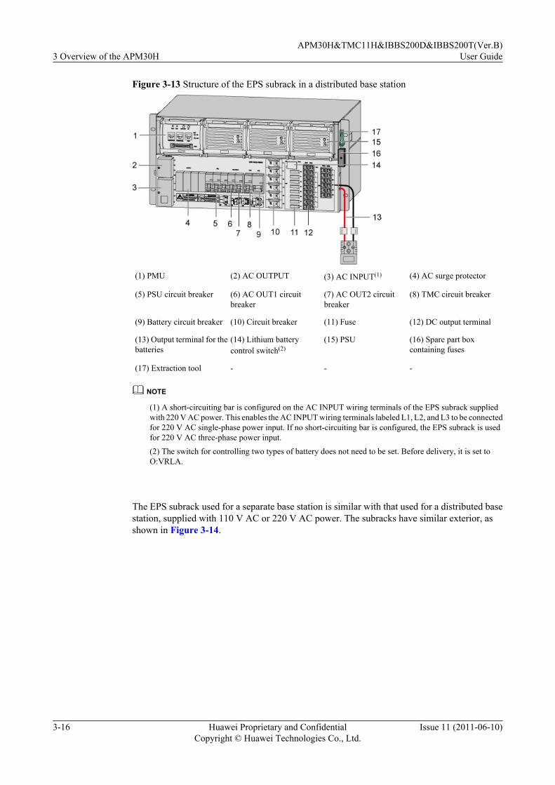
Figure 3-13 Structure of the EPS subrack in a distributed base station
(1) PMU (2) AC OUTPUT (3) AC INPUT(1) (4) AC surge protector
(5) PSU circuit breaker (6) AC OUT1 circuitbreaker
(7) AC OUT2 circuitbreaker
(8) TMC circuit breaker
(9) Battery circuit breaker (10) Circuit breaker (11) Fuse (12) DC output terminal
(13) Output terminal for thebatteries
(14) Lithium batterycontrol switch(2)
(15) PSU (16) Spare part boxcontaining fuses
(17) Extraction tool - - -
NOTE
(1) A short-circuiting bar is configured on the AC INPUT wiring terminals of the EPS subrack suppliedwith 220 V AC power. This enables the AC INPUT wiring terminals labeled L1, L2, and L3 to be connectedfor 220 V AC single-phase power input. If no short-circuiting bar is configured, the EPS subrack is usedfor 220 V AC three-phase power input.
(2) The switch for controlling two types of battery does not need to be set. Before delivery, it is set toO:VRLA.
The EPS subrack used for a separate base station is similar with that used for a distributed basestation, supplied with 110 V AC or 220 V AC power. The subracks have similar exterior, asshown in Figure 3-14.
3 Overview of the APM30HAPM30H&TMC11H&IBBS200D&IBBS200T(Ver.B)
User Guide
3-16 Huawei Proprietary and ConfidentialCopyright © Huawei Technologies Co., Ltd.
Issue 11 (2011-06-10)

Figure 3-14 Structure of the EPS subrack in a separated macro base station
(1) PMU (2) AC OUTPUT (3) AC INPUT(1) (4) AC surge protector
(5) PSU circuit breaker (6) AC OUT1 circuitbreaker
(7) AC OUT2 circuitbreaker
(8) Battery circuit breaker
(9) TMC circuit breaker (10) RFC1 circuit breaker (11) RFC2 circuit breaker (12) Fuse
(13) DC output terminal (14) Output terminal forRFC1
(15) Output terminal forRFC2
(16) Output terminal for thebatteries
(17) Lithium batterycontrol switch(2)
(18) PSU (19) Spare part boxcontaining fuses
(20) Extraction tool
NOTE
(1) A short-circuiting bar is configured on the AC INPUT wiring terminals of the EPS subrack suppliedwith 220 V AC power. This enables the AC INPUT wiring terminals labeled L1, L2, and L3 to be connectedfor 220 V AC single-phase power input. If no short-circuiting bar is configured, the EPS subrack is usedfor 220 V AC three-phase power input.
(2) The switch for controlling two types of battery does not need to be set. Before delivery, it is set toO:VRLA.
Functions
The EPS has the AC power distribution and DC power distribution functions.
l The EPS has the following AC power distribution functions:
– Providing two AC outputs, one for the Service Outlet Unit (SOU) and the other for thejunction box on the left of the cabinet. After the power distribution through the ACpower distribution box, four AC outputs are supplied to the heater or heating film.
– Reporting the AC input surge protection alarms.
l Providing 16/12 DC outputs for the distributed base station or separated macro base station
Table 3-5 describes the DC power distribution functions of the EPS of the APM30H used for adistributed base station.
APM30H&TMC11H&IBBS200D&IBBS200T(Ver.B)User Guide 3 Overview of the APM30H
Issue 11 (2011-06-10) Huawei Proprietary and ConfidentialCopyright © Huawei Technologies Co., Ltd.
3-17

Table 3-5 DC power distribution functions of the EPS subrack used for a distributed base station
DC PowerTo...
DC OutputTerminal
ProtectionComponent
Specification
Quantity DC OutputTerminalType
RRU LOAD8 toLOAD13
Circuitbreaker
20 A 6 Easy powerreceptacle(pressfittype)connector
TMC TMC 25 A 1
FAN LOAD0 Fuse 15 A 1
BBU LOAD1 andLOAD2
2
IBBS LOAD3 1
Transmission equipment
LOAD4 toLOAD7
5 A 4
Battery - Circuitbreaker
100 A 1 120 seriespowerconnector(grey)
Table 3-6 describes the DC power distribution functions of the EPS of the APM30H used for aseparated macro base station.
Table 3-6 DC power distribution functions of the EPS used for a separated macro base station
DC PowerTo...
DC OutputTerminal
ProtectionComponent
Specification
Quantity DC OutputTerminalType
RFC - Circuitbreaker
80 A 2 120 seriespowerconnector(blue)
TMC TMC 25 A 1 Easy powerreceptacle(pressfittype)connector
FAN LOAD0 Fuse 15 A 1
BBU LOAD1 andLOAD2
2
IBBS LOAD3 1
Transmission equipment
LOAD4 toLOAD7
5 A 4
3 Overview of the APM30HAPM30H&TMC11H&IBBS200D&IBBS200T(Ver.B)
User Guide
3-18 Huawei Proprietary and ConfidentialCopyright © Huawei Technologies Co., Ltd.
Issue 11 (2011-06-10)

DC PowerTo...
DC OutputTerminal
ProtectionComponent
Specification
Quantity DC OutputTerminalType
Battery - Circuitbreaker
100 A 1 120 seriespowerconnector(grey)
PMU
The Power Monitoring Unit (PMU) provides the functions of power system and storage batterymanagement, power monitoring, and alarm reporting.
Functions
The PMU performs the following functions:
l Communicates with the BBU through an RS485 serial port.
l Manages the power system and charging and discharging the storage batteries.
l Checks and reports Boolean values of the door status sensor and standby sensor, and reportsthe analog values of the temperature and humidity, storage battery temperature, and standbyanalog value.
l Monitors power supply and reports alarms, including dry contact alarms.
l Communicates with the storage battery cabinet through an RS485 serial port.
Exterior
Figure 3-15 shows the PMU.
Figure 3-15 PMU
APM30H&TMC11H&IBBS200D&IBBS200T(Ver.B)User Guide 3 Overview of the APM30H
Issue 11 (2011-06-10) Huawei Proprietary and ConfidentialCopyright © Huawei Technologies Co., Ltd.
3-19

Ports and LEDsFigure 3-16 shows the ports on the front panel of the PMU. Figure 3-17 shows the rear panelof the PMU.
Figure 3-16 Ports, LEDs, and Switch on the front panel of a PMU
(1) COM_IN port (2) LEDs
(3) COM_OUT port (4) Power test ports
(5) COM_485 port (6) Storage battery control switch
(7) COM port -
3 Overview of the APM30HAPM30H&TMC11H&IBBS200D&IBBS200T(Ver.B)
User Guide
3-20 Huawei Proprietary and ConfidentialCopyright © Huawei Technologies Co., Ltd.
Issue 11 (2011-06-10)

Figure 3-17 Rear panel of a PMU
(1) Port on the rear panel
Table 3-7 lists the ports of the PMU.
Table 3-7 Ports and switch on a PMU
Port/Switch Description
COM_IN Connects to the BBU or upper-level device and reports alarms tothe BBU
COM_OUT Connects to lower-level devices such as the EMUA and collectsalarms from lower-level devices
COM_485 Connects to the CMUA in the IBBS200D/IBBS200T and collectsalarms from the storage battery cabinet
COM Connects to the HPMI and collects alarms from the HPMI
Storage battery controlswitch
Powers on and powers off storage batteries through the ON and OFFportsl Insert a round bar into the ON port and hold it for 5s to 10s. When
you hear a click, you can verify that the storage batteries areconnected and the power-on operation is successful.
l Insert a round bar into the OFF port and hold it for 5s to 10s.When you hear a click, you can verify that the storage batteriesare disconnected and the power-off operation is successful.
Table 3-8 lists the LEDs on the panel of a PMU.
APM30H&TMC11H&IBBS200D&IBBS200T(Ver.B)User Guide 3 Overview of the APM30H
Issue 11 (2011-06-10) Huawei Proprietary and ConfidentialCopyright © Huawei Technologies Co., Ltd.
3-21

Table 3-8 LEDs on the panel of a PMU
Label Color Status Meaning
RUN Green Blinking (on for 1s andoff for 1s)
The PMU is functional and communicatingwith the BBU properly.
Blinking (on for 0.125sand off for 0.125s)
The PMU is functional, but fails tocommunicate with the BBU. If the PMU doesnot communicate with the BBU for oneminute, you can verify that communicationfails.
On or off The PMU is faulty (when it is not in thepower-on self-check status).
ALM Red On The base station reports at least one of thefollowing alarms:l Mains failure alarm (including mains
phase loss)l Mains power overvoltage or undervoltage
alarml Busbar overvoltage or undervoltage
alarml Charging overcurrentl Battery power-off alarml Battery group circuit failure alarml Environmental temperature alarml Ambient humidity alarml PSU alarml Load power-off
Off No alarm is generated.
NOTE
Within 3s to 5s after the PMU is powered on, the ALM and RUN LEDs are on simultaneously for about3s.
DIP SwitchThe DIP switch is located on the right of the PMU. The DIP switch has eight bits, where thefour least significant bits (1, 2, 3, and 4) define the monitoring address of the PMU, and the fourmost significant bits (5, 6, 7, and 8) are not defined and are reserved for future use.
ON indicates the value 1, and OFF indicates the value 0. The default monitoring address of thePMU is set to 3 before delivery, as shown in Figure 3-18.
3 Overview of the APM30HAPM30H&TMC11H&IBBS200D&IBBS200T(Ver.B)
User Guide
3-22 Huawei Proprietary and ConfidentialCopyright © Huawei Technologies Co., Ltd.
Issue 11 (2011-06-10)
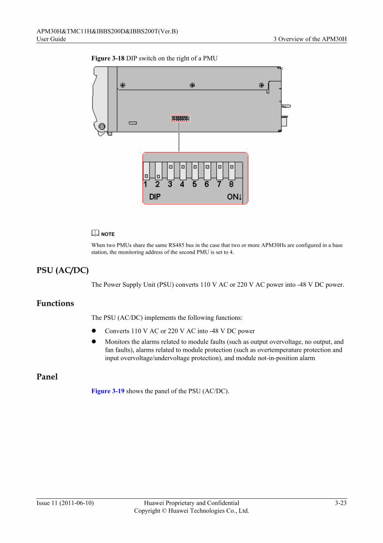
Figure 3-18 DIP switch on the right of a PMU
NOTE
When two PMUs share the same RS485 bus in the case that two or more APM30Hs are configured in a basestation, the monitoring address of the second PMU is set to 4.
PSU (AC/DC)The Power Supply Unit (PSU) converts 110 V AC or 220 V AC power into -48 V DC power.
FunctionsThe PSU (AC/DC) implements the following functions:
l Converts 110 V AC or 220 V AC into -48 V DC powerl Monitors the alarms related to module faults (such as output overvoltage, no output, and
fan faults), alarms related to module protection (such as overtemperature protection andinput overvoltage/undervoltage protection), and module not-in-position alarm
PanelFigure 3-19 shows the panel of the PSU (AC/DC).
APM30H&TMC11H&IBBS200D&IBBS200T(Ver.B)User Guide 3 Overview of the APM30H
Issue 11 (2011-06-10) Huawei Proprietary and ConfidentialCopyright © Huawei Technologies Co., Ltd.
3-23
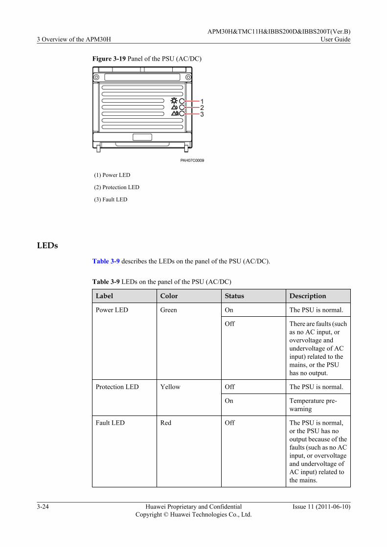
Figure 3-19 Panel of the PSU (AC/DC)
(1) Power LED
(2) Protection LED
(3) Fault LED
LEDs
Table 3-9 describes the LEDs on the panel of the PSU (AC/DC).
Table 3-9 LEDs on the panel of the PSU (AC/DC)
Label Color Status Description
Power LED Green On The PSU is normal.
Off There are faults (suchas no AC input, orovervoltage andundervoltage of ACinput) related to themains, or the PSUhas no output.
Protection LED Yellow Off The PSU is normal.
On Temperature pre-warning
Fault LED Red Off The PSU is normal,or the PSU has nooutput because of thefaults (such as no ACinput, or overvoltageand undervoltage ofAC input) related tothe mains.
3 Overview of the APM30HAPM30H&TMC11H&IBBS200D&IBBS200T(Ver.B)
User Guide
3-24 Huawei Proprietary and ConfidentialCopyright © Huawei Technologies Co., Ltd.
Issue 11 (2011-06-10)

Label Color Status Description
On The PSU has nooutput because ofoutput overvoltageshutdown, fan fault,overtemperatureshutdown, remoteshutdown, or internalproblems of the PSU.
3.4.3 Power Equipment (DC/DC)The power equipment (DC/DC) converts +24 V DC power into -48 V DC power.
Components of the Power Equipment (DC/DC)The power equipment (DC/DC) consists of the PSUs (DC/DC) and power subrack (DC/DC).
Figure 3-20 shows the power equipment (DC/DC).
Figure 3-20 Power equipment (DC/DC)
(1) PSUs (DC/DC) (2) Power subrack (DC/DC)
Table 3-10 describes the components of the power equipment (DC/DC).
Table 3-10 Components of the power equipment (DC/DC)
Component Description
PSU (DC/DC) For details, see PSU (DC/DC).
Power subrack (DC/DC) For details, see Power Subrack (DC/DC).
PSU (DC/DC)The PSU is the power supply unit. The PSU (DC/DC) converts +24 V DC power into -48 V DCpower.
APM30H&TMC11H&IBBS200D&IBBS200T(Ver.B)User Guide 3 Overview of the APM30H
Issue 11 (2011-06-10) Huawei Proprietary and ConfidentialCopyright © Huawei Technologies Co., Ltd.
3-25

Panel
Figure 3-21 shows the panel of the PSU (DC/DC).
Figure 3-21 Panel of the PSU (DC/DC)
(1) Power LED (2) Protection LED (3) Fault LED
Functionsl Converts +24 V DC power into -48 V DC power and leads the -48 V DC power into the
DCDU-01.
l Monitors the unit and reports alarms related to PSU faults (such as output overvoltage, nooutput, and fan faults), alarms related to PSU protection (such as overtemperatureprotection, and input overvoltage/undervoltage protection), and PSU out-of-positionalarms, if any.
LEDs
Table 3-11 describes the LEDs on the panel of the PSU (DC/DC).
Table 3-11 LEDs on the panel of the PSU (DC/DC)
LED Color Status Description
Power LED Green On The power supply isnormal.
Off There is no powerinput, or the fuse isdamaged.
3 Overview of the APM30HAPM30H&TMC11H&IBBS200D&IBBS200T(Ver.B)
User Guide
3-26 Huawei Proprietary and ConfidentialCopyright © Huawei Technologies Co., Ltd.
Issue 11 (2011-06-10)

LED Color Status Description
Protection LED Yellow Off The running status isnormal.
On There is abnormalinput or outputvoltage, the unit isoverheated, or theunit is not properlyinserted.
Fault LED Red Off The running status isnormal.
Blinking The fan is faulty.
Power Subrack (DC/DC)The power subrack (DC/DC) provides the power input wiring terminals, power output wiringterminals, ALM port, and PRESENT port. The terminals and ports are used for the connectionsof the +24 V input power cables, -48 V output power cables, monitoring signal cable for thePSU, and in-position signal cable for the PSU respectively.
ExteriorFigure 3-22 shows the power subrack (DC/DC).
Figure 3-22 Power Subrack (DC/DC)
(1) Power input wiringterminals
(2) PRESENT port (3) ALM port (4) Power output wiringterminals
PortsTable 3-12 describes the ports and terminals on the power subrack (DC/DC).
APM30H&TMC11H&IBBS200D&IBBS200T(Ver.B)User Guide 3 Overview of the APM30H
Issue 11 (2011-06-10) Huawei Proprietary and ConfidentialCopyright © Huawei Technologies Co., Ltd.
3-27

Table 3-12 Ports and terminals on the power subrack (DC/DC)
Terminal/Port
Label Connector Description
Power inputwiring terminal
DC INPUT OT terminal The + wiring terminals are used for theconnections of +24 V power cables, andthe - wiring terminals are used for theconnections of +24 V RTN cables.
Power outputwiring terminal
DCOUTPUT
OT terminal The LOAD- wiring terminals are usedfor the connections of the -48 V powercables, and the RTN+ wiring terminalsare used for the connections of the -48 VRTN cables.
Alarm signalport
ALM Cord endterminal
The ALM port is used for the connectionof the monitoring signal cable for thePSU.
PRESENT port PRESENT RJ-45connector
The PRESENT port is used for theconnection of the in-position signalcable for the PSU.
3.4.4 Core of the Heat ExchangerThe core of the heat exchanger extends the area for the exchange of the air inside and outsidethe cabinet, speeding up the air circulation and effectively decreasing the working temperatureof the cabinet. In addition, the core of the heat exchanger keeps the dust away from the cabinet.
ExteriorThe core of the heat exchanger is positioned on the inner side of the front door of the APM30Hcabinet. Figure 3-23 shows the core of the heat exchanger.
3 Overview of the APM30HAPM30H&TMC11H&IBBS200D&IBBS200T(Ver.B)
User Guide
3-28 Huawei Proprietary and ConfidentialCopyright © Huawei Technologies Co., Ltd.
Issue 11 (2011-06-10)

Figure 3-23 Core of the heat exchanger
3.4.5 Junction BoxThe junction box divides one AC input into four AC outputs. The AC outputs are used for theSOU and multiple heating films or heaters.
Exterior
The junction box is on the left inner side of the APM30H. Figure 3-24 shows the junction box.
Figure 3-24 Junction box
APM30H&TMC11H&IBBS200D&IBBS200T(Ver.B)User Guide 3 Overview of the APM30H
Issue 11 (2011-06-10) Huawei Proprietary and ConfidentialCopyright © Huawei Technologies Co., Ltd.
3-29

StructureFigure 3-25 shows the structure of the junction box.
Figure 3-25 Structure of the junction box
(1) L wiring terminals for four ACoutputs
(2) N wiring terminals for four ACoutputs
(3) PE wiring terminals for four ACoutputs
(4) Cable holes (5) N wiring terminals for the ACinput
(6) L wiring terminal for the ACinput
3.4.6 ELUThe Electronic Label Unit (ELU) automatically reports the information about the cabinet type,facilitating fast troubleshooting.
The ELU is on the left inner side of the IBBS200D or IBBS200T or on the right inner side ofthe APM30H, TMC11H, or RFC. Figure 3-26 shows the ELU.
3 Overview of the APM30HAPM30H&TMC11H&IBBS200D&IBBS200T(Ver.B)
User Guide
3-30 Huawei Proprietary and ConfidentialCopyright © Huawei Technologies Co., Ltd.
Issue 11 (2011-06-10)
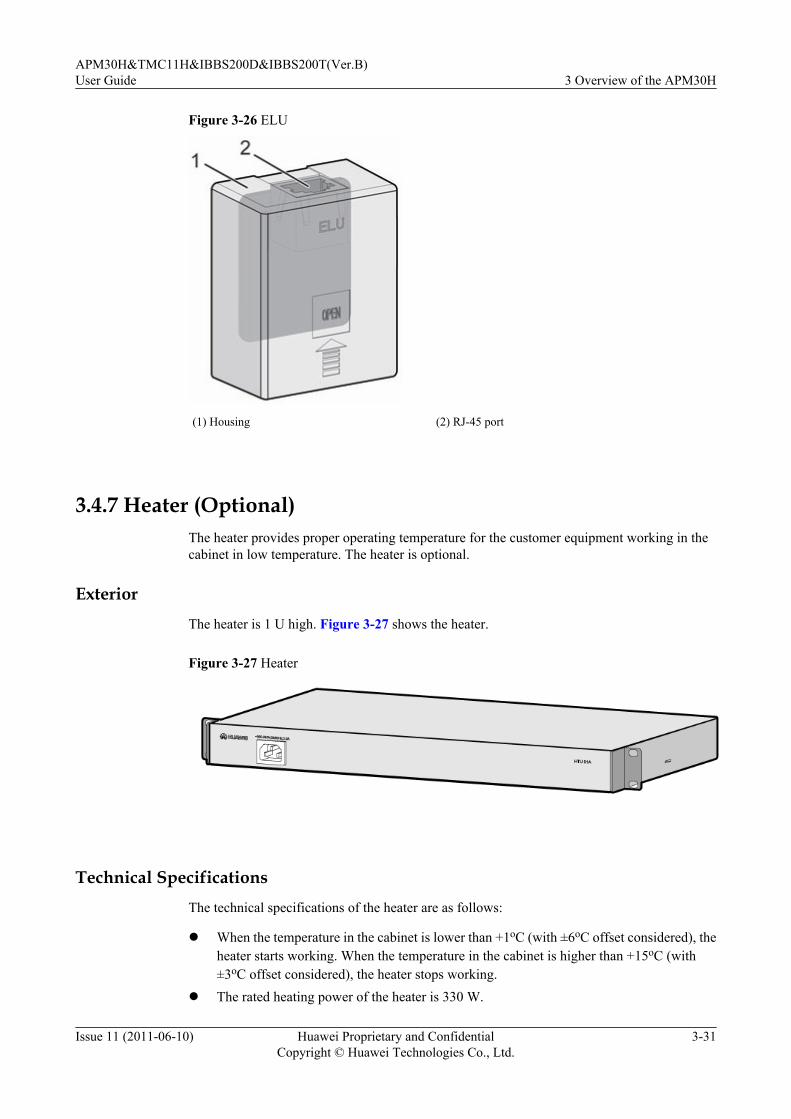
Figure 3-26 ELU
(1) Housing (2) RJ-45 port
3.4.7 Heater (Optional)The heater provides proper operating temperature for the customer equipment working in thecabinet in low temperature. The heater is optional.
ExteriorThe heater is 1 U high. Figure 3-27 shows the heater.
Figure 3-27 Heater
Technical SpecificationsThe technical specifications of the heater are as follows:
l When the temperature in the cabinet is lower than +1oC (with ±6oC offset considered), theheater starts working. When the temperature in the cabinet is higher than +15oC (with±3oC offset considered), the heater stops working.
l The rated heating power of the heater is 330 W.
APM30H&TMC11H&IBBS200D&IBBS200T(Ver.B)User Guide 3 Overview of the APM30H
Issue 11 (2011-06-10) Huawei Proprietary and ConfidentialCopyright © Huawei Technologies Co., Ltd.
3-31

3.4.8 SOU (Optional)The Service Outlet Unit (SOU) feeds AC power to the customer equipment. The SOU is optional.
Technical Specifications
Table 3-13 describes the technical specifications of the SOU.
Table 3-13 Technical specifications of the SOU
Item Specification
Dimensions (W x D x H) 482.6 mm x 91 mm x 55 mm
Weight 1.5 kg
Input voltage range 200 V AC to 240 V AC
Maximum input current 10 A
Output voltage range 200 V AC to 240 V AC
Maximum output current 10 A
Operating frequency 50 Hz or 60 Hz
Operating temperature -40oC to + 55oC
Altitude ≤ 4,000 mNOTE
Above the altitude of 3,000 m, the maximumoperating temperature decreases by 1oC each timethe altitude increases by 100 m.
Protection class IP20
Exterior
Figure 3-28 shows the SOU.
Figure 3-28 SOU
(1) Power supply socket (2) Breaker (3) Socket (Europe)
3 Overview of the APM30HAPM30H&TMC11H&IBBS200D&IBBS200T(Ver.B)
User Guide
3-32 Huawei Proprietary and ConfidentialCopyright © Huawei Technologies Co., Ltd.
Issue 11 (2011-06-10)

The SOU can be used for different types of sockets in different countries. The types of socketsthat are supported are: North America, European standard, multi-standard, and UK types. Figure3-29 shows the different types of sockets.
Figure 3-29 Different types of sockets
3.4.9 Door Status SensorThe door status sensor monitors the opening and closing of the front door of the cabinet.
The door status sensor consists of the magnet part and switch part.
Figure 3-30 shows the magnet part of the door status sensor.
Figure 3-30 Magnet part of the door status sensor
Figure 3-31 shows the switch part of the door status sensor.
APM30H&TMC11H&IBBS200D&IBBS200T(Ver.B)User Guide 3 Overview of the APM30H
Issue 11 (2011-06-10) Huawei Proprietary and ConfidentialCopyright © Huawei Technologies Co., Ltd.
3-33

Figure 3-31 Switch part of the door status sensor
3.5 APM30H CablesThe APM30H cables consist of the PGND cable, input power cable, environment monitoringsignal cable, and monitoring signal cable for the PMU.
3.5.1 PGND CableThe PGND cables consist of the PGND cable for the cabinet and PGND cables for the modulesin the cabinet.
3.5.2 Input Power Cables for the APM30HThe power input cables for the APM30H lead external power to the power system. Differentconfigurations of the power system can support different types of power input, including the220 V AC single-phase power input, 220 V AC three-phase power input, 110 V AC dual livewire power input, and +24 V DC power input.
3.5.3 Power Cable for the SOUThe power cable for the SOU feeds AC power into the SOU from the AC OUTPUT port of theEPS.
3.5.4 Power Cable for the HeaterThe power cable for the heater feeds the AC input power into the heater from the junction box.
3.5.5 Power Cable for the Fan Box in the APM30HThe power cable feeds -48 V DC power into the fan box in the APM30H.
3.5.6 ELU Signal CableThe ELU (Electronic Label Unit) signal cable transmits the information about the cabinet typereported by the ELU to the CMUA.
3.5.7 APM30H Door Status Monitoring CableThe APM30H door status monitoring cable transmits the alarm signals to the PMU through theHPMI.
3.5.8 Monitoring Signal Cable for the Fan on the Front Door
3 Overview of the APM30HAPM30H&TMC11H&IBBS200D&IBBS200T(Ver.B)
User Guide
3-34 Huawei Proprietary and ConfidentialCopyright © Huawei Technologies Co., Ltd.
Issue 11 (2011-06-10)

The monitoring signal cable feeds power into the fan on the front door of the APM30H orTMC11H and transmits fan monitoring signals to the CMUA.
3.5.9 Environment Monitoring Signal CableThe environment monitoring signal cable connects the PMU to the HPMI. It reports the alarmsignals collected by the HPMI to the PMU.
3.5.10 Monitoring Signal Transfer CableThe monitoring signal transfer cable connects the PMU to the CMUA, and it transmits the RS485signals collected by the PMU to the BBU through the CMUA.
3.5.1 PGND CableThe PGND cables consist of the PGND cable for the cabinet and PGND cables for the modulesin the cabinet.
Exterior
All PGND cables have the same exterior. Both ends of the cables are linked with OT terminals.Figure 3-32 and Figure 3-33 show the PGND cables.
Figure 3-32 PGND cable for the cabinet
OT terminal
Figure 3-33 PGND cable for the modules
OT terminal
Cable Description
Table 3-14 describes the PGND cables.
Table 3-14 PGND cables
Cable Color Cross-Sectional Area
PGND cable for the cabinet Green and yellow 16 mm2
APM30H&TMC11H&IBBS200D&IBBS200T(Ver.B)User Guide 3 Overview of the APM30H
Issue 11 (2011-06-10) Huawei Proprietary and ConfidentialCopyright © Huawei Technologies Co., Ltd.
3-35

Cable Color Cross-Sectional Area
PGND cable for the modulesin the cabinet
Green and yellow 6 mm2
3.5.2 Input Power Cables for the APM30HThe power input cables for the APM30H lead external power to the power system. Differentconfigurations of the power system can support different types of power input, including the220 V AC single-phase power input, 220 V AC three-phase power input, 110 V AC dual livewire power input, and +24 V DC power input.
ExteriorFigure 3-34 shows the 220 V AC single-phase input power cable.
Figure 3-34 220 V AC single-phase input power cable
(1) OT terminal (6 mm2, M6)
NOTE
The number of wires of an AC input power cable varies according to the cable type. Figure 3-34 showsthe 220 V AC single-phase input power cable.
Figure 3-35 shows the +24 V DC power input cable.
Figure 3-35 +24 V DC power cable
(1) OT terminal (25mm2, M6)
NOTE
The +24 V DC input power cable consists of two pairs of wires, with each pair containing a red wire and a blackwire.
3 Overview of the APM30HAPM30H&TMC11H&IBBS200D&IBBS200T(Ver.B)
User Guide
3-36 Huawei Proprietary and ConfidentialCopyright © Huawei Technologies Co., Ltd.
Issue 11 (2011-06-10)
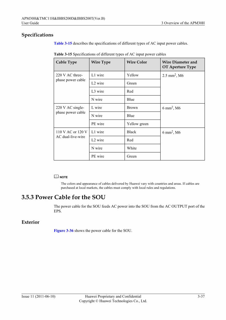
SpecificationsTable 3-15 describes the specifications of different types of AC input power cables.
Table 3-15 Specifications of different types of AC input power cables
Cable Type Wire Type Wire Color Wire Diameter andOT Aperture Type
220 V AC three-phase power cable
L1 wire Yellow 2.5 mm2, M6
L2 wire Green
L3 wire Red
N wire Blue
220 V AC single-phase power cable
L wire Brown 6 mm2, M6
N wire Blue
PE wire Yellow green
110 V AC or 120 VAC dual-live-wire
L1 wire Black 6 mm2, M6
L2 wire Red
N wire White
PE wire Green
NOTE
The colors and appearance of cables delivered by Huawei vary with countries and areas. If cables arepurchased at local markets, the cables must comply with local rules and regulations.
3.5.3 Power Cable for the SOUThe power cable for the SOU feeds AC power into the SOU from the AC OUTPUT port of theEPS.
ExteriorFigure 3-36 shows the power cable for the SOU.
APM30H&TMC11H&IBBS200D&IBBS200T(Ver.B)User Guide 3 Overview of the APM30H
Issue 11 (2011-06-10) Huawei Proprietary and ConfidentialCopyright © Huawei Technologies Co., Ltd.
3-37
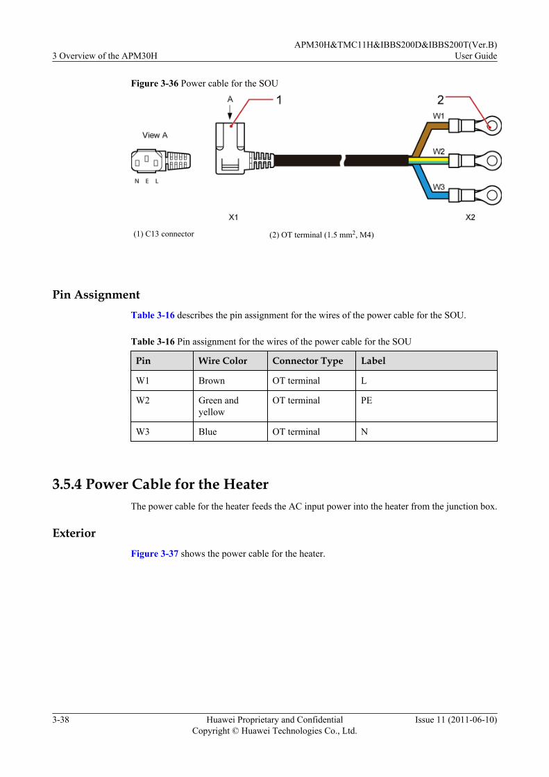
Figure 3-36 Power cable for the SOU
(1) C13 connector (2) OT terminal (1.5 mm2, M4)
Pin AssignmentTable 3-16 describes the pin assignment for the wires of the power cable for the SOU.
Table 3-16 Pin assignment for the wires of the power cable for the SOU
Pin Wire Color Connector Type Label
W1 Brown OT terminal L
W2 Green andyellow
OT terminal PE
W3 Blue OT terminal N
3.5.4 Power Cable for the HeaterThe power cable for the heater feeds the AC input power into the heater from the junction box.
ExteriorFigure 3-37 shows the power cable for the heater.
3 Overview of the APM30HAPM30H&TMC11H&IBBS200D&IBBS200T(Ver.B)
User Guide
3-38 Huawei Proprietary and ConfidentialCopyright © Huawei Technologies Co., Ltd.
Issue 11 (2011-06-10)
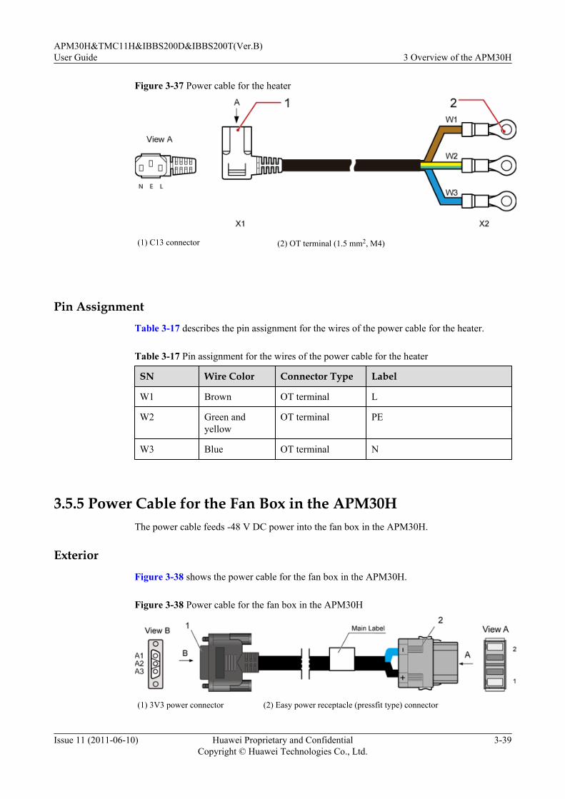
Figure 3-37 Power cable for the heater
(1) C13 connector (2) OT terminal (1.5 mm2, M4)
Pin AssignmentTable 3-17 describes the pin assignment for the wires of the power cable for the heater.
Table 3-17 Pin assignment for the wires of the power cable for the heater
SN Wire Color Connector Type Label
W1 Brown OT terminal L
W2 Green andyellow
OT terminal PE
W3 Blue OT terminal N
3.5.5 Power Cable for the Fan Box in the APM30HThe power cable feeds -48 V DC power into the fan box in the APM30H.
ExteriorFigure 3-38 shows the power cable for the fan box in the APM30H.
Figure 3-38 Power cable for the fan box in the APM30H
(1) 3V3 power connector (2) Easy power receptacle (pressfit type) connector
APM30H&TMC11H&IBBS200D&IBBS200T(Ver.B)User Guide 3 Overview of the APM30H
Issue 11 (2011-06-10) Huawei Proprietary and ConfidentialCopyright © Huawei Technologies Co., Ltd.
3-39

3.5.6 ELU Signal CableThe ELU (Electronic Label Unit) signal cable transmits the information about the cabinet typereported by the ELU to the CMUA.
Exterior
Figure 3-39 shows the ELU signal cable.
Figure 3-39 ELU signal cable
(1) RJ-45 connector
Pin Assignment
Table 3-18 describes the pin assignment for the wires of the ELU signal cable.
Table 3-18 Pin assignment for the wires of the ELU signal cable
X1 End X2 End Wire Color Type
X1.1 X2.1 White Twisted pair
X1.2 X2.2 Orange
X1.3 X2.3 White Twisted pair
X1.6 X2.6 Green
X1.5 X2.5 White Twisted pair
X1.4 X2.4 Blue
X1.7 X2.7 White Twisted pair
X1.8 X2.8 Brown
3.5.7 APM30H Door Status Monitoring CableThe APM30H door status monitoring cable transmits the alarm signals to the PMU through theHPMI.
3 Overview of the APM30HAPM30H&TMC11H&IBBS200D&IBBS200T(Ver.B)
User Guide
3-40 Huawei Proprietary and ConfidentialCopyright © Huawei Technologies Co., Ltd.
Issue 11 (2011-06-10)

ExteriorFigure 3-40 shows the APM30H door status monitoring cable.
Figure 3-40 APM30H door status monitoring cable
The APM30H door status monitoring cable is described as follows:l The cable labeled 1 has a straight 2-pin connector at one end, which is connected to the
HPMI. The other end of the cable is a bare wire and a cord end terminal, which are connectedto the door status sensor and wiring terminal block respectively.
l The cable labeled 2 has a bare wire at one end, which is connected to the door status sensor.The other end of the cable is a cord end terminal, which is connected to the wiring terminalblock.
l The cable labeled 3 has two cord end terminals at both ends, which are connected to twoports in the wiring terminal block at a side.
3.5.8 Monitoring Signal Cable for the Fan on the Front DoorThe monitoring signal cable feeds power into the fan on the front door of the APM30H orTMC11H and transmits fan monitoring signals to the CMUA.
ExteriorFigure 3-41 shows the monitoring signal cable for the fan on the front door.
APM30H&TMC11H&IBBS200D&IBBS200T(Ver.B)User Guide 3 Overview of the APM30H
Issue 11 (2011-06-10) Huawei Proprietary and ConfidentialCopyright © Huawei Technologies Co., Ltd.
3-41
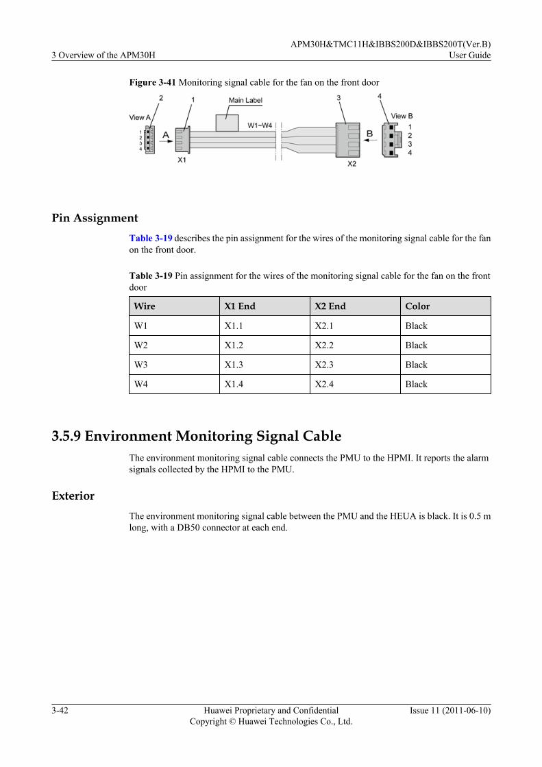
Figure 3-41 Monitoring signal cable for the fan on the front door
Pin AssignmentTable 3-19 describes the pin assignment for the wires of the monitoring signal cable for the fanon the front door.
Table 3-19 Pin assignment for the wires of the monitoring signal cable for the fan on the frontdoor
Wire X1 End X2 End Color
W1 X1.1 X2.1 Black
W2 X1.2 X2.2 Black
W3 X1.3 X2.3 Black
W4 X1.4 X2.4 Black
3.5.9 Environment Monitoring Signal CableThe environment monitoring signal cable connects the PMU to the HPMI. It reports the alarmsignals collected by the HPMI to the PMU.
ExteriorThe environment monitoring signal cable between the PMU and the HEUA is black. It is 0.5 mlong, with a DB50 connector at each end.
3 Overview of the APM30HAPM30H&TMC11H&IBBS200D&IBBS200T(Ver.B)
User Guide
3-42 Huawei Proprietary and ConfidentialCopyright © Huawei Technologies Co., Ltd.
Issue 11 (2011-06-10)
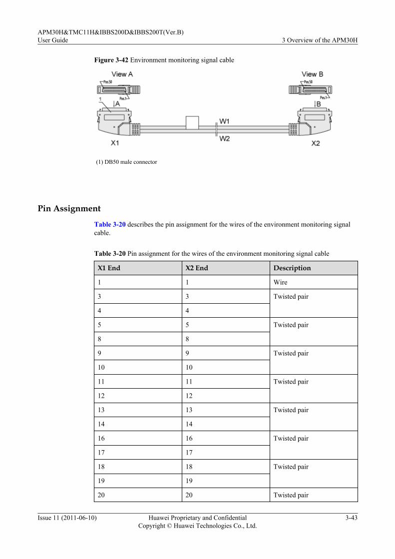
Figure 3-42 Environment monitoring signal cable
(1) DB50 male connector
Pin Assignment
Table 3-20 describes the pin assignment for the wires of the environment monitoring signalcable.
Table 3-20 Pin assignment for the wires of the environment monitoring signal cable
X1 End X2 End Description
1 1 Wire
3 3 Twisted pair
4 4
5 5 Twisted pair
8 8
9 9 Twisted pair
10 10
11 11 Twisted pair
12 12
13 13 Twisted pair
14 14
16 16 Twisted pair
17 17
18 18 Twisted pair
19 19
20 20 Twisted pair
APM30H&TMC11H&IBBS200D&IBBS200T(Ver.B)User Guide 3 Overview of the APM30H
Issue 11 (2011-06-10) Huawei Proprietary and ConfidentialCopyright © Huawei Technologies Co., Ltd.
3-43
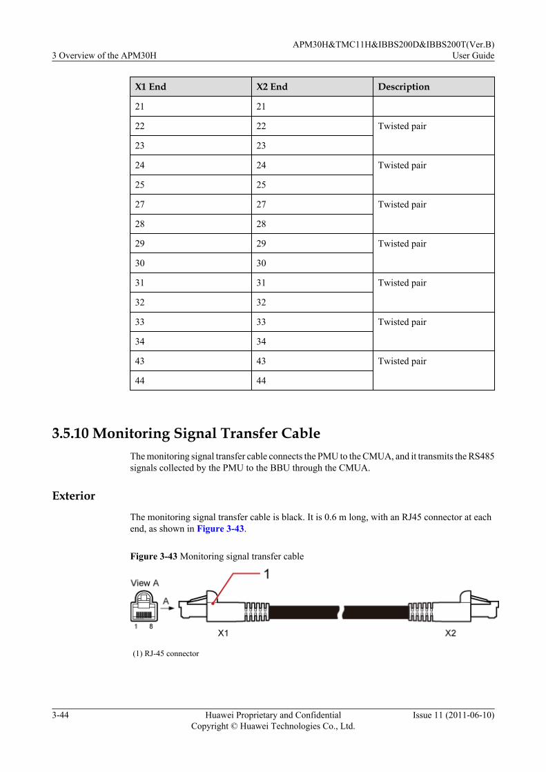
X1 End X2 End Description
21 21
22 22 Twisted pair
23 23
24 24 Twisted pair
25 25
27 27 Twisted pair
28 28
29 29 Twisted pair
30 30
31 31 Twisted pair
32 32
33 33 Twisted pair
34 34
43 43 Twisted pair
44 44
3.5.10 Monitoring Signal Transfer CableThe monitoring signal transfer cable connects the PMU to the CMUA, and it transmits the RS485signals collected by the PMU to the BBU through the CMUA.
Exterior
The monitoring signal transfer cable is black. It is 0.6 m long, with an RJ45 connector at eachend, as shown in Figure 3-43.
Figure 3-43 Monitoring signal transfer cable
(1) RJ-45 connector
3 Overview of the APM30HAPM30H&TMC11H&IBBS200D&IBBS200T(Ver.B)
User Guide
3-44 Huawei Proprietary and ConfidentialCopyright © Huawei Technologies Co., Ltd.
Issue 11 (2011-06-10)

Pin AssignmentTable 3-21 describes the pin assignment for the wires of the monitoring signal transfer cable.
Table 3-21 Pin assignment of the monitoring signal transfer cable
X1 End X2 End Pin Assignment
X1.1 X2.1 Twisted pair
X1.2 X2.2
X1.3 X2.3 Twisted pair
X1.6 X2.6
X1.4 X2.4 Twisted pair
X1.5 X2.5
X1.7 X2.7 Twisted pair
X1.8 X2.8
APM30H&TMC11H&IBBS200D&IBBS200T(Ver.B)User Guide 3 Overview of the APM30H
Issue 11 (2011-06-10) Huawei Proprietary and ConfidentialCopyright © Huawei Technologies Co., Ltd.
3-45


4 Overview of the IBBS200T
About This Chapter
This describes the exterior, structure, components, and cables of the IBBS200T.
4.1 Exterior of the IBBS200TThe IBBS200T is elegantly designed. It is small in size and easy to transport.
4.2 Structure of the IBBS200TThe IBBS200T has a highly integrated and modular structure design. The power distributionbox (PDB) of the IBBS200T is installed to the upper right inside the cabinet, and the CMUA isinstalled on the inner side of the cabinet door.
4.3 Cable Connections of the IBBS200TThe cables of the IBBS200T are power cables and signal cables.
4.4 IBBS200T ComponentsThe components of the IBBS200T consist of the TEC cooler, power distribution box, CMUA,and storage batteries.
4.5 IBBS200T CablesThe IBBS200T cables consist of the equipotential cable, input power cables for the batteries,power cable for the TEC cooler, and monitoring signal cable.
APM30H&TMC11H&IBBS200D&IBBS200T(Ver.B)User Guide 4 Overview of the IBBS200T
Issue 11 (2011-06-10) Huawei Proprietary and ConfidentialCopyright © Huawei Technologies Co., Ltd.
4-1

4.1 Exterior of the IBBS200TThe IBBS200T is elegantly designed. It is small in size and easy to transport.
Figure 4-1 shows exterior of the IBBS200T.
Figure 4-1 Exterior of the IBBS200T
4.2 Structure of the IBBS200TThe IBBS200T has a highly integrated and modular structure design. The power distributionbox (PDB) of the IBBS200T is installed to the upper right inside the cabinet, and the CMUA isinstalled on the inner side of the cabinet door.
Figure 4-2 shows the internal structure of the IBBS200T.
4 Overview of the IBBS200TAPM30H&TMC11H&IBBS200D&IBBS200T(Ver.B)
User Guide
4-2 Huawei Proprietary and ConfidentialCopyright © Huawei Technologies Co., Ltd.
Issue 11 (2011-06-10)
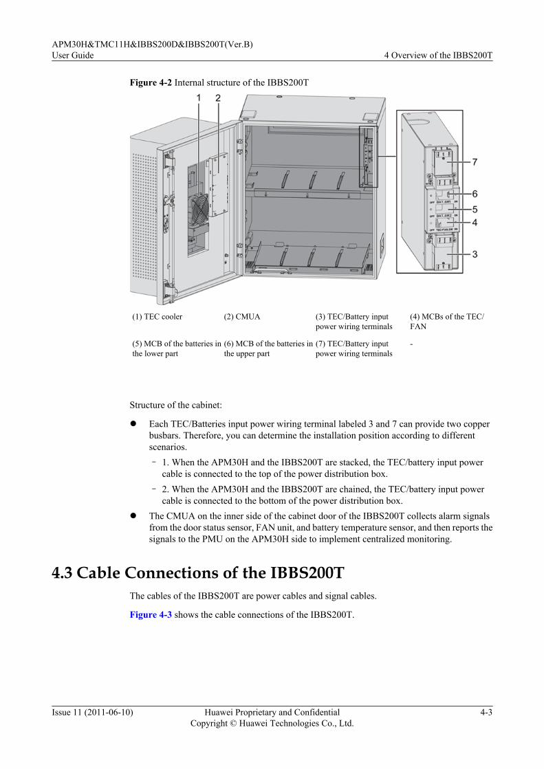
Figure 4-2 Internal structure of the IBBS200T
(1) TEC cooler (2) CMUA (3) TEC/Battery inputpower wiring terminals
(4) MCBs of the TEC/FAN
(5) MCB of the batteries inthe lower part
(6) MCB of the batteries inthe upper part
(7) TEC/Battery inputpower wiring terminals
-
Structure of the cabinet:
l Each TEC/Batteries input power wiring terminal labeled 3 and 7 can provide two copperbusbars. Therefore, you can determine the installation position according to differentscenarios.– 1. When the APM30H and the IBBS200T are stacked, the TEC/battery input power
cable is connected to the top of the power distribution box.– 2. When the APM30H and the IBBS200T are chained, the TEC/battery input power
cable is connected to the bottom of the power distribution box.l The CMUA on the inner side of the cabinet door of the IBBS200T collects alarm signals
from the door status sensor, FAN unit, and battery temperature sensor, and then reports thesignals to the PMU on the APM30H side to implement centralized monitoring.
4.3 Cable Connections of the IBBS200TThe cables of the IBBS200T are power cables and signal cables.
Figure 4-3 shows the cable connections of the IBBS200T.
APM30H&TMC11H&IBBS200D&IBBS200T(Ver.B)User Guide 4 Overview of the IBBS200T
Issue 11 (2011-06-10) Huawei Proprietary and ConfidentialCopyright © Huawei Technologies Co., Ltd.
4-3

Figure 4-3 Cable connections of the IBBS200T
(1) Negative power cable for theupper-level batteries
(2) Power transfer cable for theTEC cooler
(3) Negative power cable for thelower-level batteries
(4) Input power cable for thebatteries
(5) Input power cable for the TECcooler
-
4.4 IBBS200T ComponentsThe components of the IBBS200T consist of the TEC cooler, power distribution box, CMUA,and storage batteries.
4.4.1 TEC CoolerThe TEC cooler is installed in the TEC cooler hood on the front door of the cabinet. The TECcooler consists of the TEC module, inner air circulation fan, outer air circulation fan, coolingfin, and monitoring board.
4.4.2 Power Distribution BoxThe power distribution box (PDB) is installed at the upper right of the cabinet, implementingconversion and distribution of power supply to the TEC cooler or fan box and to the storagebatteries.
4.4.3 CMUAThis section describes the central monitoring unit type A (CMUA).
4.4.4 Storage BatteryThis section provides the exterior of storage batteries and describes technical specifications andconfiguration of storage batteries.
4.4.5 ELU
4 Overview of the IBBS200TAPM30H&TMC11H&IBBS200D&IBBS200T(Ver.B)
User Guide
4-4 Huawei Proprietary and ConfidentialCopyright © Huawei Technologies Co., Ltd.
Issue 11 (2011-06-10)

The Electronic Label Unit (ELU) automatically reports the information about the cabinet type,facilitating fast troubleshooting.
4.4.6 Door Status SensorThe door status sensor monitors the opening and closing of the front door of the cabinet.
4.4.7 Temperature Sensor for the Storage BatteriesThe temperature sensor for the storage batteries monitors the temperature in the storage batterycabinet in real time and reports the information to the CMUA.
4.4.1 TEC CoolerThe TEC cooler is installed in the TEC cooler hood on the front door of the cabinet. The TECcooler consists of the TEC module, inner air circulation fan, outer air circulation fan, coolingfin, and monitoring board.
Exterior
Figure 4-4 shows the TEC cooler.
Figure 4-4 TEC cooler
APM30H&TMC11H&IBBS200D&IBBS200T(Ver.B)User Guide 4 Overview of the IBBS200T
Issue 11 (2011-06-10) Huawei Proprietary and ConfidentialCopyright © Huawei Technologies Co., Ltd.
4-5
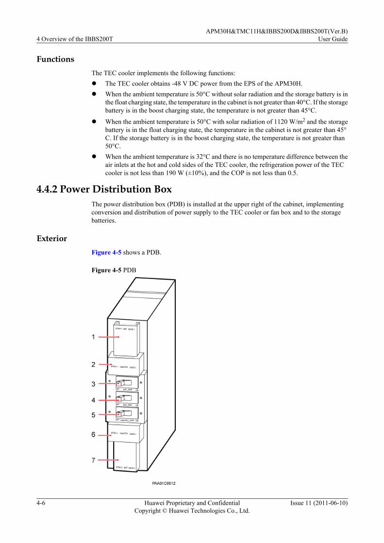
FunctionsThe TEC cooler implements the following functions:l The TEC cooler obtains -48 V DC power from the EPS of the APM30H.l When the ambient temperature is 50°C without solar radiation and the storage battery is in
the float charging state, the temperature in the cabinet is not greater than 40°C. If the storagebattery is in the boost charging state, the temperature is not greater than 45°C.
l When the ambient temperature is 50°C with solar radiation of 1120 W/m2 and the storagebattery is in the float charging state, the temperature in the cabinet is not greater than 45°C. If the storage battery is in the boost charging state, the temperature is not greater than50°C.
l When the ambient temperature is 32°C and there is no temperature difference between theair inlets at the hot and cold sides of the TEC cooler, the refrigeration power of the TECcooler is not less than 190 W (±10%), and the COP is not less than 0.5.
4.4.2 Power Distribution BoxThe power distribution box (PDB) is installed at the upper right of the cabinet, implementingconversion and distribution of power supply to the TEC cooler or fan box and to the storagebatteries.
ExteriorFigure 4-5 shows a PDB.
Figure 4-5 PDB
4 Overview of the IBBS200TAPM30H&TMC11H&IBBS200D&IBBS200T(Ver.B)
User Guide
4-6 Huawei Proprietary and ConfidentialCopyright © Huawei Technologies Co., Ltd.
Issue 11 (2011-06-10)
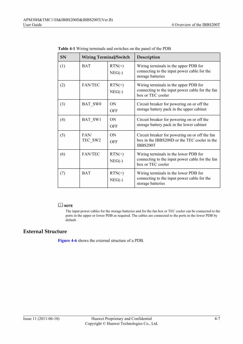
Table 4-1 Wiring terminals and switches on the panel of the PDB
SN Wiring Terminal/Switch Description
(1) BAT RTN(+)NEG(-)
Wiring terminals in the upper PDB forconnecting to the input power cable for thestorage batteries
(2) FAN/TEC RTN(+)NEG(-)
Wiring terminals in the upper PDB forconnecting to the input power cable for the fanbox or TEC cooler
(3) BAT_SW0 ONOFF
Circuit breaker for powering on or off thestorage battery pack in the upper cabinet
(4) BAT_SW1 ONOFF
Circuit breaker for powering on or off thestorage battery pack in the lower cabinet
(5) FAN/TEC_SW2
ONOFF
Circuit breaker for powering on or off the fanbox in the IBBS200D or the TEC cooler in theIBBS200T
(6) FAN/TEC RTN(+)NEG(-)
Wiring terminals in the lower PDB forconnecting to the input power cable for the fanbox or TEC cooler
(7) BAT RTN(+)NEG(-)
Wiring terminals in the lower PDB forconnecting to the input power cable for thestorage batteries
NOTEThe input power cables for the storage batteries and for the fan box or TEC cooler can be connected to theports in the upper or lower PDB as required. The cables are connected to the ports in the lower PDB bydefault.
External StructureFigure 4-6 shows the external structure of a PDB.
APM30H&TMC11H&IBBS200D&IBBS200T(Ver.B)User Guide 4 Overview of the IBBS200T
Issue 11 (2011-06-10) Huawei Proprietary and ConfidentialCopyright © Huawei Technologies Co., Ltd.
4-7
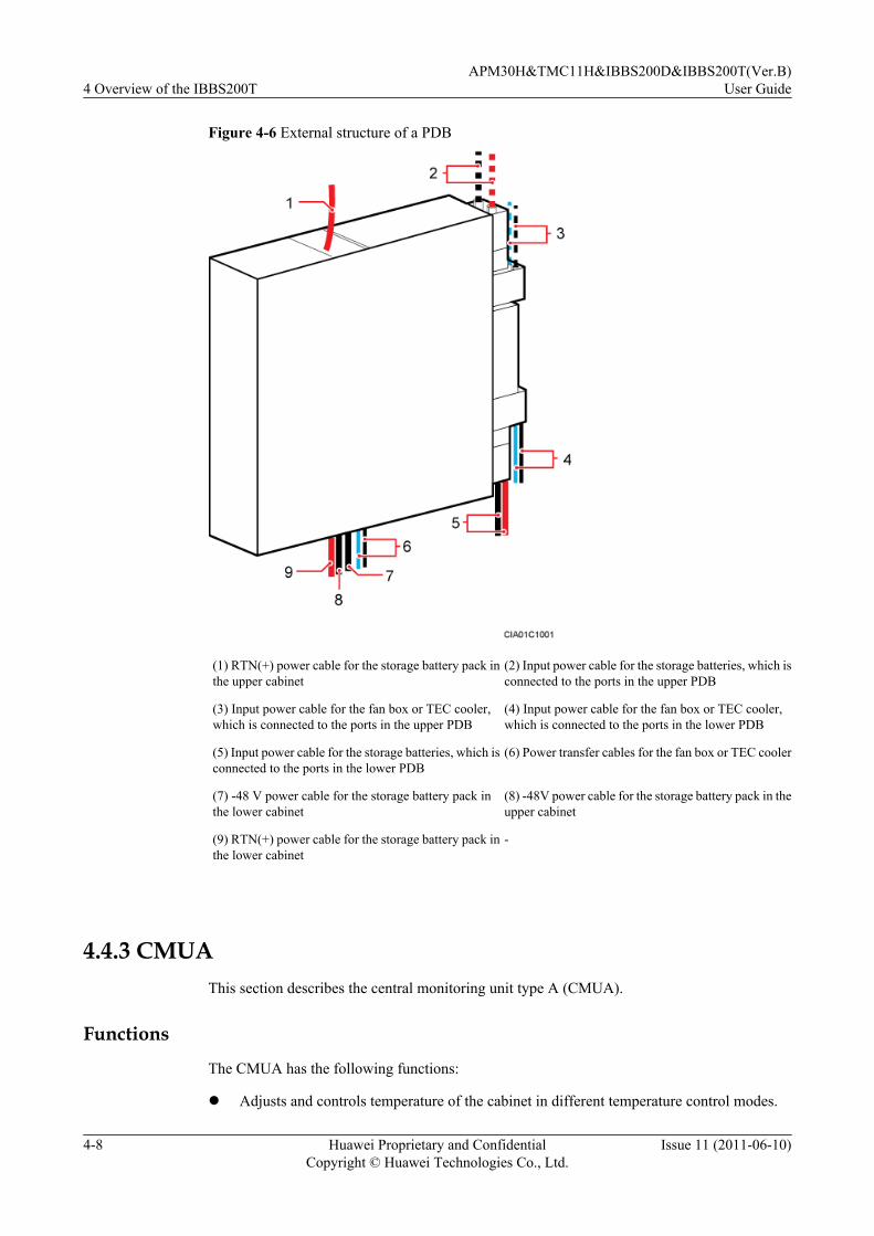
Figure 4-6 External structure of a PDB
(1) RTN(+) power cable for the storage battery pack inthe upper cabinet
(2) Input power cable for the storage batteries, which isconnected to the ports in the upper PDB
(3) Input power cable for the fan box or TEC cooler,which is connected to the ports in the upper PDB
(4) Input power cable for the fan box or TEC cooler,which is connected to the ports in the lower PDB
(5) Input power cable for the storage batteries, which isconnected to the ports in the lower PDB
(6) Power transfer cables for the fan box or TEC cooler
(7) -48 V power cable for the storage battery pack inthe lower cabinet
(8) -48V power cable for the storage battery pack in theupper cabinet
(9) RTN(+) power cable for the storage battery pack inthe lower cabinet
-
4.4.3 CMUAThis section describes the central monitoring unit type A (CMUA).
Functions
The CMUA has the following functions:
l Adjusts and controls temperature of the cabinet in different temperature control modes.
4 Overview of the IBBS200TAPM30H&TMC11H&IBBS200D&IBBS200T(Ver.B)
User Guide
4-8 Huawei Proprietary and ConfidentialCopyright © Huawei Technologies Co., Ltd.
Issue 11 (2011-06-10)

l Reserves a port for three Boolean inputs and detects Boolean alarms in the cabinet. Theremote detection, however, is not supported.
l Provides a port for the RJ45 connector to enable electronic label and cabinet type detection.
ExteriorFigure 4-7 shows a CMUA.
Figure 4-7 CMUA
PortsFigure 4-8 shows the ports on the CMUA, and Table 4-2 describes the ports.
Figure 4-8 Ports on a CMUA (plan view)
APM30H&TMC11H&IBBS200D&IBBS200T(Ver.B)User Guide 4 Overview of the IBBS200T
Issue 11 (2011-06-10) Huawei Proprietary and ConfidentialCopyright © Huawei Technologies Co., Ltd.
4-9

Table 4-2 Ports on a CMUA
Silkscreen on thePort
Port Function Port Relationship with the RelatedCabinet(1)(2)
APM30H
TMC11H
RFC IBBS200D
IBBS200T
l TEM(in theRFC)
l TEM_BAT(in theIBBS200D/IBBS200T)
l In the RFC: connects tothe temperature sensor atthe air inlet of the cabinetand receives temperaturealarms.
l In the IBBS200D/IBBS200T: connects tothe storage batterytemperature sensor in theIBBS200D/IBBS200Tand receives storagebattery temperaturealarms.
Reserved
Reserved
Mandatory
Mandatory
Mandatory
COM_OUT
Communication port forlower-level cascadingl Connecting to the PMU
(in an APM30H)l Connecting to the lower-
level CMUA (in an RFC,TMC11H, IBBS200D, orIBBS200T)
- - - - -
COM_IN Communication port forupper-level cascadingl Connecting to the BBU
(in an APM30H)l Connecting to the BBU or
upper-level CMUA (in anRFC or TMC11H)
l Connecting to the PMU orupper-level CMUA (in anIBBS200D or IBBS200T)
- - - - -
ELU Connects to the ElectronicLabel Unit (ELU) andreceives ELU-related alarms.
Mandatory
Mandatory
Mandatory
Mandatory
Mandatory
GATE Connects the door statussensor and receives doorstatus alarms.
Reserved
Mandatory
Mandatory
Mandatory
Mandatory
IN0, IN1,IN2
Provides one Boolean input ateach port.
Reserved
Reserved
Reserved
Reserved
Reserved
4 Overview of the IBBS200TAPM30H&TMC11H&IBBS200D&IBBS200T(Ver.B)
User Guide
4-10 Huawei Proprietary and ConfidentialCopyright © Huawei Technologies Co., Ltd.
Issue 11 (2011-06-10)
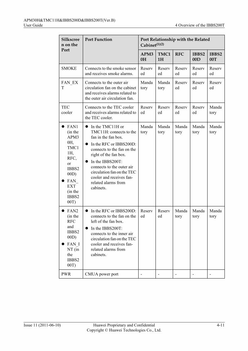
Silkscreen on thePort
Port Function Port Relationship with the RelatedCabinet(1)(2)
APM30H
TMC11H
RFC IBBS200D
IBBS200T
SMOKE Connects to the smoke sensorand receives smoke alarms.
Reserved
Reserved
Reserved
Reserved
Reserved
FAN_EXT
Connects to the outer aircirculation fan on the cabinetand receives alarms related tothe outer air circulation fan.
Mandatory
Mandatory
Reserved
Reserved
Reserved
TECcooler
Connects to the TEC coolerand receives alarms related tothe TEC cooler.
Reserved
Reserved
Reserved
Reserved
Mandatory
l FAN1(in theAPM30H,TMC11H,RFC,orIBBS200D)
l FAN_EXT(in theIBBS200T)
l In the TMC11H orTMC11H: connects to thefan in the fan box.
l In the RFC or IBBS200D:connects to the fan on theright of the fan box.
l In the IBBS200T:connects to the outer aircirculation fan on the TECcooler and receives fan-related alarms fromcabinets.
Mandatory
Mandatory
Mandatory
Mandatory
Mandatory
l FAN2(in theRFCandIBBS200D)
l FAN_INT (intheIBBS200T)
l In the RFC or IBBS200D:connects to the fan on theleft of the fan box.
l In the IBBS200T:connects to the inner aircirculation fan on the TECcooler and receives fan-related alarms fromcabinets.
Reserved
Reserved
Mandatory
Mandatory
Mandatory
PWR CMUA power port - - - - -
APM30H&TMC11H&IBBS200D&IBBS200T(Ver.B)User Guide 4 Overview of the IBBS200T
Issue 11 (2011-06-10) Huawei Proprietary and ConfidentialCopyright © Huawei Technologies Co., Ltd.
4-11

NOTE
(1) Mandatory monitoring devices are installed in the cabinet before delivery, and related monitoring signalcables are connected before delivery. Optional devices are configured based on customer requirements,and related cables must be connected on site. For details about how to connect the cables, see BTS3900AInstallation Guide.
(2) For details about the positions of devices monitored by the CMUA, see Structure of the BTS3900ACabinet.
LEDTable 4-3 describes the LEDs on the CMUA.
Table 4-3 LEDs
Label Color Status Meaning
RUN Green Blinking (on for 1s andoff for 1s)
The board is functional and communicateswith the BBU properly.
Blinking (on for 0.125sand off for 0.125s)
The board is functional, but fails tocommunicate with the BBUs. If the boarddoes not communicate with the BBU for oneminute, you can verify that communicationfails.
On or off The board is faulty (when it is not in thepower-on self-check status).
ALM Red Off No alarm is generated.
On An alarm is generated, and the board must bereplaced.
Blinking (on for 1s andoff for 1s)
An alarm is generated. The alarm may becaused by the faults of related boards or ports.Therefore, you cannot determine whether toreplace the board.
DIP SwitchesThere are three DIP switches on the CMUA. They are SW1, SW2, and SW3, which are used toset the working mode of the CMUA according to the cabinet type. Figure 4-9 shows the positionsof the DIP switches on the CMUA.
4 Overview of the IBBS200TAPM30H&TMC11H&IBBS200D&IBBS200T(Ver.B)
User Guide
4-12 Huawei Proprietary and ConfidentialCopyright © Huawei Technologies Co., Ltd.
Issue 11 (2011-06-10)

Figure 4-9 Positions of the DIP switches on the CMUA (plan view)
The DIP switches in different types of cabinet are set in different modes, as shown in Figure4-10.
Figure 4-10 DIP switch settings of the CMUA in different cabinets
NOTE
The red rectangles in Figure 4-10 show the positions for installing jumper caps.
4.4.4 Storage BatteryThis section provides the exterior of storage batteries and describes technical specifications andconfiguration of storage batteries.
NOTEThe exterior and technical specifications of the storage battery may vary according to manufacturer. Thefollowing description is based on common 12 V 92 Ah storage batteries.
ExteriorFigure 4-11 shows the exterior of the 12 V 92 Ah storage battery.
APM30H&TMC11H&IBBS200D&IBBS200T(Ver.B)User Guide 4 Overview of the IBBS200T
Issue 11 (2011-06-10) Huawei Proprietary and ConfidentialCopyright © Huawei Technologies Co., Ltd.
4-13

Figure 4-11 Exterior of the 12 V 92 Ah storage battery
Technical SpecificationsTable 4-4 describes the technical specifications of the 12 V 92 Ah storage battery.
Table 4-4 Technical specifications of the 12 V 92 Ah storage battery
Type Dimensions (W x H x D) Weight
12 V 92 Ah 105 mm x 287 mm x 390 mm 33.5 kg
108 mm x 287 mm x 393 mm 35 kg
ConfigurationThe cabinet supports two types of storage battery packs: 48 V 92 Ah and 48 V 184 Ah.
l The upper and lower 48 V 92 Ah storage battery packs can be connected in parallel toprovide 48 V 184 Ah power.
l Each storage battery pack contains four single storage batteries.
4.4.5 ELUThe Electronic Label Unit (ELU) automatically reports the information about the cabinet type,facilitating fast troubleshooting.
The ELU is on the left inner side of the IBBS200D or IBBS200T or on the right inner side ofthe APM30H, TMC11H, or RFC. Figure 4-12 shows the ELU.
4 Overview of the IBBS200TAPM30H&TMC11H&IBBS200D&IBBS200T(Ver.B)
User Guide
4-14 Huawei Proprietary and ConfidentialCopyright © Huawei Technologies Co., Ltd.
Issue 11 (2011-06-10)
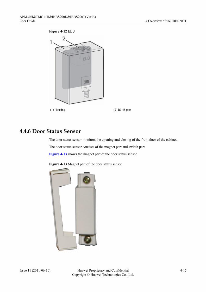
Figure 4-12 ELU
(1) Housing (2) RJ-45 port
4.4.6 Door Status SensorThe door status sensor monitors the opening and closing of the front door of the cabinet.
The door status sensor consists of the magnet part and switch part.
Figure 4-13 shows the magnet part of the door status sensor.
Figure 4-13 Magnet part of the door status sensor
APM30H&TMC11H&IBBS200D&IBBS200T(Ver.B)User Guide 4 Overview of the IBBS200T
Issue 11 (2011-06-10) Huawei Proprietary and ConfidentialCopyright © Huawei Technologies Co., Ltd.
4-15

Figure 4-14 shows the switch part of the door status sensor.
Figure 4-14 Switch part of the door status sensor
4.4.7 Temperature Sensor for the Storage BatteriesThe temperature sensor for the storage batteries monitors the temperature in the storage batterycabinet in real time and reports the information to the CMUA.
Installation PositionFigure 4-15 and Figure 4-16 show the installation position of the temperature sensor for thestorage batteries in the IBBS200D and IBBS200T.
Figure 4-15 Installation position of the temperature sensor for the storage batteries in theIBBS200D
4 Overview of the IBBS200TAPM30H&TMC11H&IBBS200D&IBBS200T(Ver.B)
User Guide
4-16 Huawei Proprietary and ConfidentialCopyright © Huawei Technologies Co., Ltd.
Issue 11 (2011-06-10)
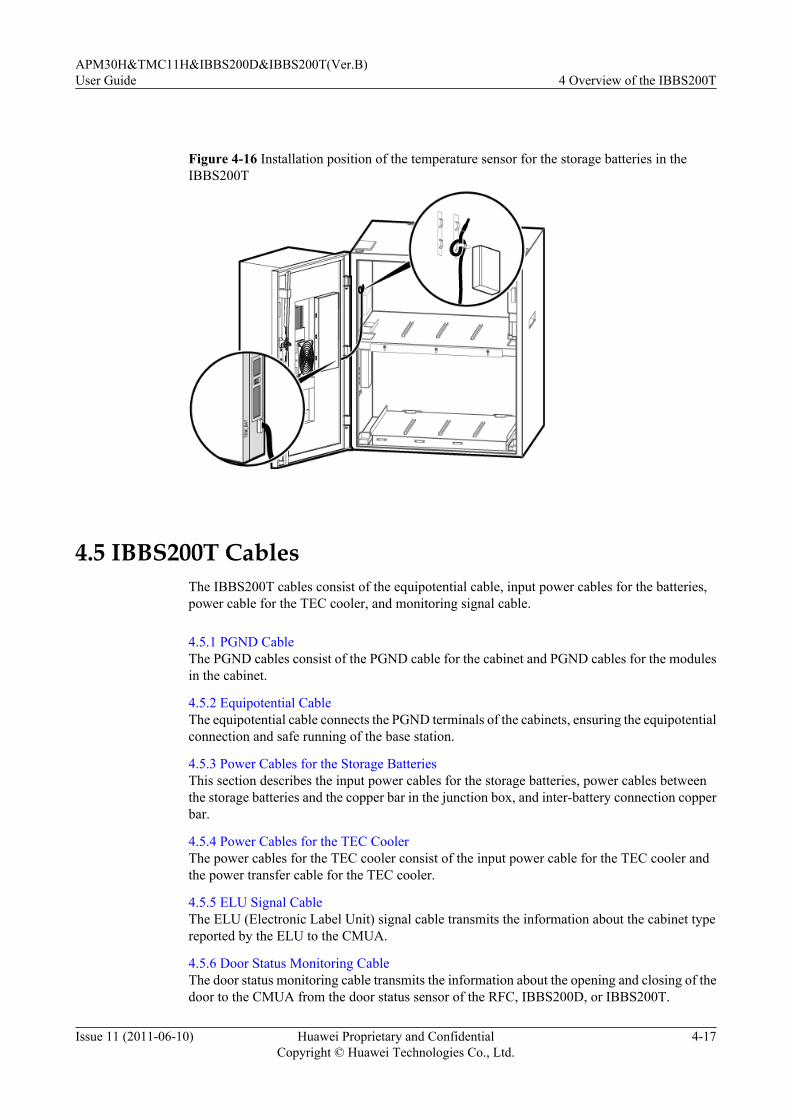
Figure 4-16 Installation position of the temperature sensor for the storage batteries in theIBBS200T
4.5 IBBS200T CablesThe IBBS200T cables consist of the equipotential cable, input power cables for the batteries,power cable for the TEC cooler, and monitoring signal cable.
4.5.1 PGND CableThe PGND cables consist of the PGND cable for the cabinet and PGND cables for the modulesin the cabinet.
4.5.2 Equipotential CableThe equipotential cable connects the PGND terminals of the cabinets, ensuring the equipotentialconnection and safe running of the base station.
4.5.3 Power Cables for the Storage BatteriesThis section describes the input power cables for the storage batteries, power cables betweenthe storage batteries and the copper bar in the junction box, and inter-battery connection copperbar.
4.5.4 Power Cables for the TEC CoolerThe power cables for the TEC cooler consist of the input power cable for the TEC cooler andthe power transfer cable for the TEC cooler.
4.5.5 ELU Signal CableThe ELU (Electronic Label Unit) signal cable transmits the information about the cabinet typereported by the ELU to the CMUA.
4.5.6 Door Status Monitoring CableThe door status monitoring cable transmits the information about the opening and closing of thedoor to the CMUA from the door status sensor of the RFC, IBBS200D, or IBBS200T.
APM30H&TMC11H&IBBS200D&IBBS200T(Ver.B)User Guide 4 Overview of the IBBS200T
Issue 11 (2011-06-10) Huawei Proprietary and ConfidentialCopyright © Huawei Technologies Co., Ltd.
4-17

4.5.7 Monitoring Signal Cable for the Storage Battery CabinetThe monitoring signal cable for the storage battery cabinet collects and transmits the monitoringsignals of the IBBS200D or IBBS200T to the PMU.
4.5.1 PGND CableThe PGND cables consist of the PGND cable for the cabinet and PGND cables for the modulesin the cabinet.
Exterior
All PGND cables have the same exterior. Both ends of the cables are linked with OT terminals.Figure 4-17 and Figure 4-18 show the PGND cables.
Figure 4-17 PGND cable for the cabinet
OT terminal
Figure 4-18 PGND cable for the modules
OT terminal
Cable Description
Table 4-5 describes the PGND cables.
Table 4-5 PGND cables
Cable Color Cross-Sectional Area
PGND cable for the cabinet Green and yellow 16 mm2
PGND cable for the modulesin the cabinet
Green and yellow 6 mm2
4 Overview of the IBBS200TAPM30H&TMC11H&IBBS200D&IBBS200T(Ver.B)
User Guide
4-18 Huawei Proprietary and ConfidentialCopyright © Huawei Technologies Co., Ltd.
Issue 11 (2011-06-10)
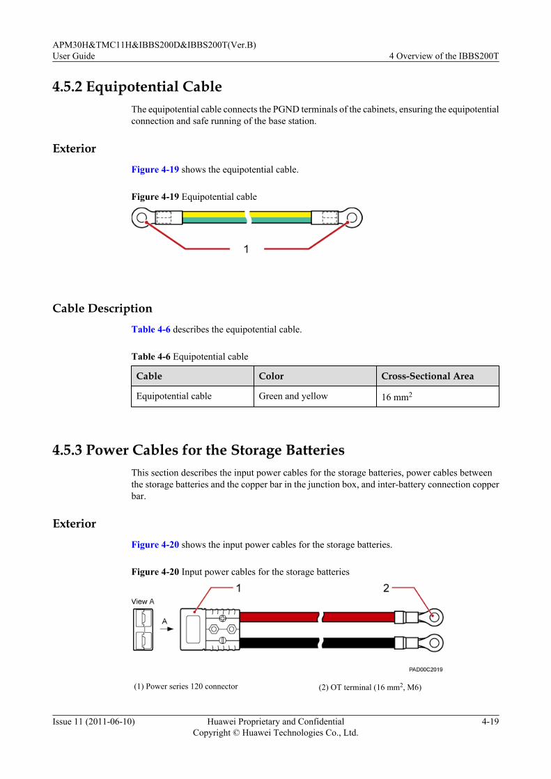
4.5.2 Equipotential CableThe equipotential cable connects the PGND terminals of the cabinets, ensuring the equipotentialconnection and safe running of the base station.
ExteriorFigure 4-19 shows the equipotential cable.
Figure 4-19 Equipotential cable
Cable DescriptionTable 4-6 describes the equipotential cable.
Table 4-6 Equipotential cable
Cable Color Cross-Sectional Area
Equipotential cable Green and yellow 16 mm2
4.5.3 Power Cables for the Storage BatteriesThis section describes the input power cables for the storage batteries, power cables betweenthe storage batteries and the copper bar in the junction box, and inter-battery connection copperbar.
ExteriorFigure 4-20 shows the input power cables for the storage batteries.
Figure 4-20 Input power cables for the storage batteries
(1) Power series 120 connector (2) OT terminal (16 mm2, M6)
APM30H&TMC11H&IBBS200D&IBBS200T(Ver.B)User Guide 4 Overview of the IBBS200T
Issue 11 (2011-06-10) Huawei Proprietary and ConfidentialCopyright © Huawei Technologies Co., Ltd.
4-19

Figure 4-21 shows the power cable between the storage batteries and the copper bar in thejunction box.
Figure 4-21 Power cable between the storage batteries and the copper bar in the junction box
(1) OT terminal (16 mm2, M6)
The inter-battery connection copper bar between storage batteries is delivered with the storagebatteries. Figure 4-22 shows the inter-battery connection copper bar.
Figure 4-22 Inter-battery connection copper bar
Specificationsl Of the input power cables for the storage batteries, the RTN(+) cable is red, with a cross-
sectional area of 16 mm2, and the NEG(-) cable is black, with a cross-sectional area of 16mm2.
l Of the power cables between the storage batteries and the copper bar in the junction box,the RTN(+) cable is red, with a cross-sectional area of 16 mm2, and the NEG(-) cable isblack, with a cross-sectional area of 16 mm2.
4.5.4 Power Cables for the TEC CoolerThe power cables for the TEC cooler consist of the input power cable for the TEC cooler andthe power transfer cable for the TEC cooler.
Exterior
Figure 4-23 shows the input power cable for the TEC cooler.
4 Overview of the IBBS200TAPM30H&TMC11H&IBBS200D&IBBS200T(Ver.B)
User Guide
4-20 Huawei Proprietary and ConfidentialCopyright © Huawei Technologies Co., Ltd.
Issue 11 (2011-06-10)
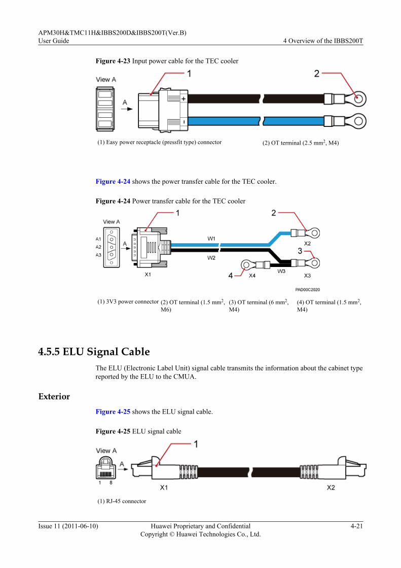
Figure 4-23 Input power cable for the TEC cooler
(1) Easy power receptacle (pressfit type) connector (2) OT terminal (2.5 mm2, M4)
Figure 4-24 shows the power transfer cable for the TEC cooler.
Figure 4-24 Power transfer cable for the TEC cooler
(1) 3V3 power connector (2) OT terminal (1.5 mm2,M6)
(3) OT terminal (6 mm2,M4)
(4) OT terminal (1.5 mm2,M4)
4.5.5 ELU Signal CableThe ELU (Electronic Label Unit) signal cable transmits the information about the cabinet typereported by the ELU to the CMUA.
ExteriorFigure 4-25 shows the ELU signal cable.
Figure 4-25 ELU signal cable
(1) RJ-45 connector
APM30H&TMC11H&IBBS200D&IBBS200T(Ver.B)User Guide 4 Overview of the IBBS200T
Issue 11 (2011-06-10) Huawei Proprietary and ConfidentialCopyright © Huawei Technologies Co., Ltd.
4-21

Pin Assignment
Table 4-7 describes the pin assignment for the wires of the ELU signal cable.
Table 4-7 Pin assignment for the wires of the ELU signal cable
X1 End X2 End Wire Color Type
X1.1 X2.1 White Twisted pair
X1.2 X2.2 Orange
X1.3 X2.3 White Twisted pair
X1.6 X2.6 Green
X1.5 X2.5 White Twisted pair
X1.4 X2.4 Blue
X1.7 X2.7 White Twisted pair
X1.8 X2.8 Brown
4.5.6 Door Status Monitoring CableThe door status monitoring cable transmits the information about the opening and closing of thedoor to the CMUA from the door status sensor of the RFC, IBBS200D, or IBBS200T.
Exterior
The door status monitoring cables are two black cables, and both ends of each cable are barewires. Figure 4-26 shows the door status monitoring cable.
Figure 4-26 Door status monitoring cable
4.5.7 Monitoring Signal Cable for the Storage Battery CabinetThe monitoring signal cable for the storage battery cabinet collects and transmits the monitoringsignals of the IBBS200D or IBBS200T to the PMU.
Exterior
Figure 4-27 shows the monitoring signal cable for the storage battery cabinet.
4 Overview of the IBBS200TAPM30H&TMC11H&IBBS200D&IBBS200T(Ver.B)
User Guide
4-22 Huawei Proprietary and ConfidentialCopyright © Huawei Technologies Co., Ltd.
Issue 11 (2011-06-10)
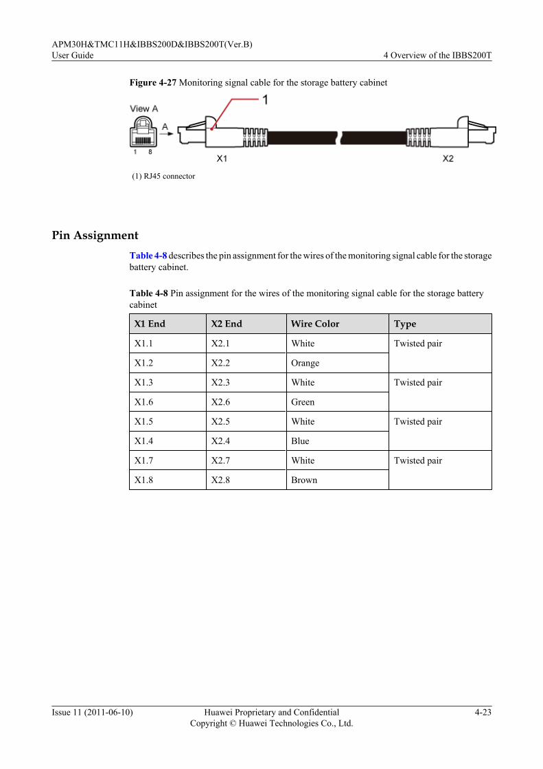
Figure 4-27 Monitoring signal cable for the storage battery cabinet
(1) RJ45 connector
Pin AssignmentTable 4-8 describes the pin assignment for the wires of the monitoring signal cable for the storagebattery cabinet.
Table 4-8 Pin assignment for the wires of the monitoring signal cable for the storage batterycabinet
X1 End X2 End Wire Color Type
X1.1 X2.1 White Twisted pair
X1.2 X2.2 Orange
X1.3 X2.3 White Twisted pair
X1.6 X2.6 Green
X1.5 X2.5 White Twisted pair
X1.4 X2.4 Blue
X1.7 X2.7 White Twisted pair
X1.8 X2.8 Brown
APM30H&TMC11H&IBBS200D&IBBS200T(Ver.B)User Guide 4 Overview of the IBBS200T
Issue 11 (2011-06-10) Huawei Proprietary and ConfidentialCopyright © Huawei Technologies Co., Ltd.
4-23


5 Overview of the IBBS200D
About This Chapter
This describes the exterior, structure, components, and cables of the IBBS200D.
5.1 Exterior of the IBBS200D CabinetThe IBBS200D cabinet is elegantly designed. It is small in size and easy to transport.
5.2 IBBS200D StructureThe IBBS200D has a modular and integrated design, with the power distribution devices at theupper right of the cabinet and the monitoring devices inside the cabinet door.
5.3 Cable Connections of the IBBS200DThis describes the cable connections of the IBBS200D.
5.4 IBBS200D ComponentsThe components of the IBBS200D consist of the fans, fan box, CMUA, power distribution box,storage batteries, and heating film. The heating film is optional.
5.5 IBBS200D CablesThe IBBS200D cables consist of the equipotential cable, input power cables for the batteries,power cable for the fans, input power cable for the heating film, and monitoring signal cable.
APM30H&TMC11H&IBBS200D&IBBS200T(Ver.B)User Guide 5 Overview of the IBBS200D
Issue 11 (2011-06-10) Huawei Proprietary and ConfidentialCopyright © Huawei Technologies Co., Ltd.
5-1
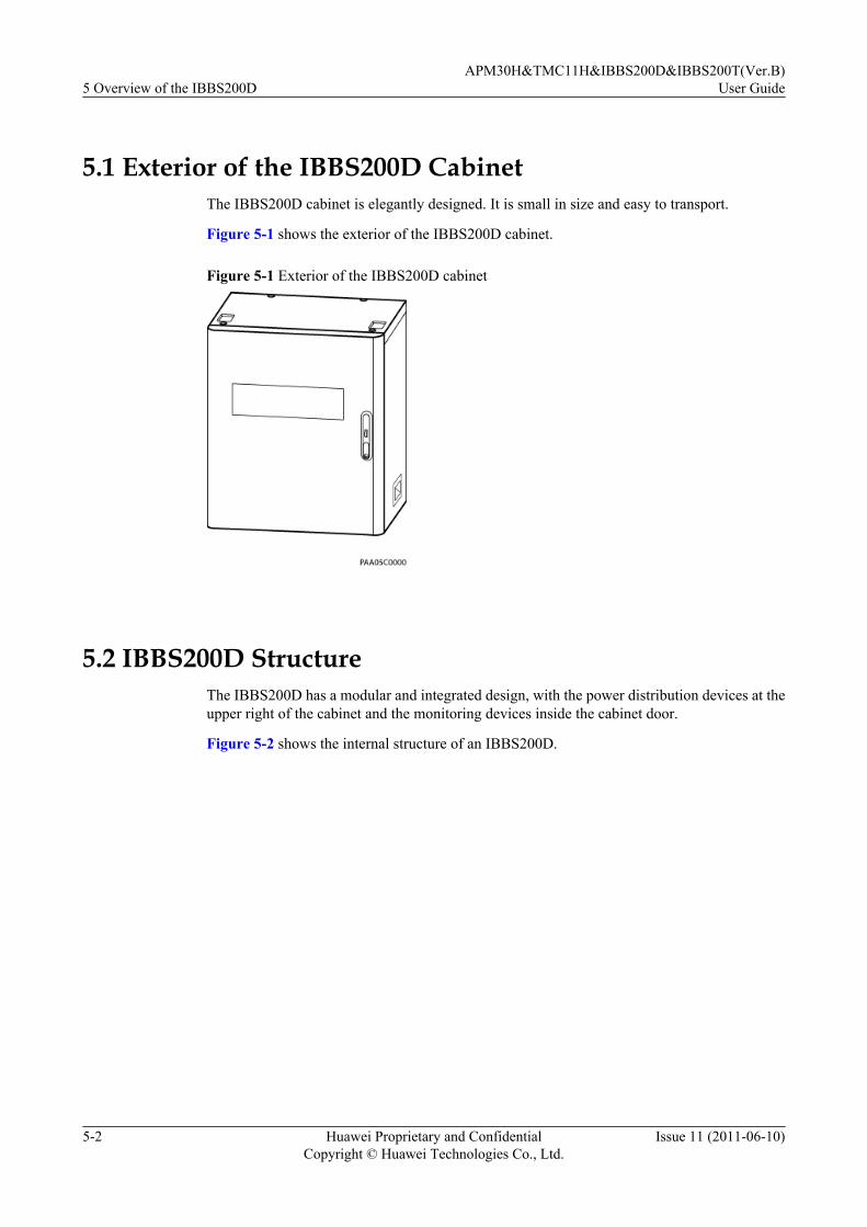
5.1 Exterior of the IBBS200D CabinetThe IBBS200D cabinet is elegantly designed. It is small in size and easy to transport.
Figure 5-1 shows the exterior of the IBBS200D cabinet.
Figure 5-1 Exterior of the IBBS200D cabinet
5.2 IBBS200D StructureThe IBBS200D has a modular and integrated design, with the power distribution devices at theupper right of the cabinet and the monitoring devices inside the cabinet door.
Figure 5-2 shows the internal structure of an IBBS200D.
5 Overview of the IBBS200DAPM30H&TMC11H&IBBS200D&IBBS200T(Ver.B)
User Guide
5-2 Huawei Proprietary and ConfidentialCopyright © Huawei Technologies Co., Ltd.
Issue 11 (2011-06-10)

Figure 5-2 Internal structure of an IBBS200D
(1) Fans (2) CMUA (3) ELU
(4) Power distribution box (5) Storage batteries (6) Heating-film power cables for the junction box
NOTE
l Alarm signals collected from the door status sensor, fans, and temperature sensor for storage batteriesare transmitted to the central monitoring unit type A (CMUA) inside the IBBS200D door, and thentransferred to the power monitoring unit (PMU) in the APM30H. This achieves centralized alarmmonitoring.
l The temperature sensor for storage batteries is installed on the left of the battery compartment in theupper IBBS200D. For details, see 5.4.8 Temperature Sensor for the Storage Batteries.
5.3 Cable Connections of the IBBS200DThis describes the cable connections of the IBBS200D.
Figure 5-3 shows the cable connections of the IBBS200D.
APM30H&TMC11H&IBBS200D&IBBS200T(Ver.B)User Guide 5 Overview of the IBBS200D
Issue 11 (2011-06-10) Huawei Proprietary and ConfidentialCopyright © Huawei Technologies Co., Ltd.
5-3

Figure 5-3 Cable connections of the IBBS200D
(1) 5.5.3 Power Cables for theStorage Batteries
(2) 5.5.4 Power Cables for the Fansin the IBBS200D
(3) Power cable for the heating film
(4) 5.5.5 Power Cable for theHeating Film
(5) 5.5.3 Power Cables for theStorage Batteries
(6) 5.5.3 Power Cables for theStorage Batteries
(7) 5.5.4 Power Cables for the Fansin the IBBS200D
- -
5.4 IBBS200D ComponentsThe components of the IBBS200D consist of the fans, fan box, CMUA, power distribution box,storage batteries, and heating film. The heating film is optional.
5.4.1 Fan BoxThe fan box is installed on the front door of the cabinet and houses the fans and CMUA.
5.4.2 Power Distribution BoxThe power distribution box (PDB) is installed at the upper right of the cabinet, implementingconversion and distribution of power supply to the TEC cooler or fan box and to the storagebatteries.
5.4.3 CMUAThis section describes the central monitoring unit type A (CMUA).
5.4.4 Storage BatteryThis section provides the exterior of storage batteries and describes technical specifications andconfiguration of storage batteries.
5.4.5 ELU
5 Overview of the IBBS200DAPM30H&TMC11H&IBBS200D&IBBS200T(Ver.B)
User Guide
5-4 Huawei Proprietary and ConfidentialCopyright © Huawei Technologies Co., Ltd.
Issue 11 (2011-06-10)

The Electronic Label Unit (ELU) automatically reports the information about the cabinet type,facilitating fast troubleshooting.
5.4.6 Heating FilmThis section describes the exterior, functions, and technical specifications of the heating film.The heating film is optional.
5.4.7 Door Status SensorThe door status sensor monitors the opening and closing of the front door of the cabinet.
5.4.8 Temperature Sensor for the Storage BatteriesThe temperature sensor for the storage batteries monitors the temperature in the storage batterycabinet in real time and reports the information to the CMUA.
5.4.1 Fan BoxThe fan box is installed on the front door of the cabinet and houses the fans and CMUA.
Exterior
Figure 5-4 shows the fan box.
Figure 5-4 Fan box
Functions
The fan box implements the following functions:
l The fans speed up the circulation of the air inside and outside the cabinet and keep thetemperature in the cabinet in a normal range, ensuring optimum performance of the storagebatteries.
APM30H&TMC11H&IBBS200D&IBBS200T(Ver.B)User Guide 5 Overview of the IBBS200D
Issue 11 (2011-06-10) Huawei Proprietary and ConfidentialCopyright © Huawei Technologies Co., Ltd.
5-5

l The CMUA collects the alarm signals from the components such as the door status sensor,temperature sensor of the storage battery, fan, and smoke sensor. Then, the monitoring unittransmits the alarm signals to the PMU through the RS485 signals.
5.4.2 Power Distribution BoxThe power distribution box (PDB) is installed at the upper right of the cabinet, implementingconversion and distribution of power supply to the TEC cooler or fan box and to the storagebatteries.
Exterior
Figure 5-5 shows a PDB.
Figure 5-5 PDB
Table 5-1 Wiring terminals and switches on the panel of the PDB
SN Wiring Terminal/Switch Description
(1) BAT RTN(+)NEG(-)
Wiring terminals in the upper PDB forconnecting to the input power cable for thestorage batteries
5 Overview of the IBBS200DAPM30H&TMC11H&IBBS200D&IBBS200T(Ver.B)
User Guide
5-6 Huawei Proprietary and ConfidentialCopyright © Huawei Technologies Co., Ltd.
Issue 11 (2011-06-10)

SN Wiring Terminal/Switch Description
(2) FAN/TEC RTN(+)NEG(-)
Wiring terminals in the upper PDB forconnecting to the input power cable for the fanbox or TEC cooler
(3) BAT_SW0 ONOFF
Circuit breaker for powering on or off thestorage battery pack in the upper cabinet
(4) BAT_SW1 ONOFF
Circuit breaker for powering on or off thestorage battery pack in the lower cabinet
(5) FAN/TEC_SW2
ONOFF
Circuit breaker for powering on or off the fanbox in the IBBS200D or the TEC cooler in theIBBS200T
(6) FAN/TEC RTN(+)NEG(-)
Wiring terminals in the lower PDB forconnecting to the input power cable for the fanbox or TEC cooler
(7) BAT RTN(+)NEG(-)
Wiring terminals in the lower PDB forconnecting to the input power cable for thestorage batteries
NOTEThe input power cables for the storage batteries and for the fan box or TEC cooler can be connected to theports in the upper or lower PDB as required. The cables are connected to the ports in the lower PDB bydefault.
External StructureFigure 5-6 shows the external structure of a PDB.
APM30H&TMC11H&IBBS200D&IBBS200T(Ver.B)User Guide 5 Overview of the IBBS200D
Issue 11 (2011-06-10) Huawei Proprietary and ConfidentialCopyright © Huawei Technologies Co., Ltd.
5-7

Figure 5-6 External structure of a PDB
(1) RTN(+) power cable for the storage battery pack inthe upper cabinet
(2) Input power cable for the storage batteries, which isconnected to the ports in the upper PDB
(3) Input power cable for the fan box or TEC cooler,which is connected to the ports in the upper PDB
(4) Input power cable for the fan box or TEC cooler,which is connected to the ports in the lower PDB
(5) Input power cable for the storage batteries, which isconnected to the ports in the lower PDB
(6) Power transfer cables for the fan box or TEC cooler
(7) -48 V power cable for the storage battery pack inthe lower cabinet
(8) -48V power cable for the storage battery pack in theupper cabinet
(9) RTN(+) power cable for the storage battery pack inthe lower cabinet
-
5.4.3 CMUAThis section describes the central monitoring unit type A (CMUA).
Functions
The CMUA has the following functions:
l Adjusts and controls temperature of the cabinet in different temperature control modes.
5 Overview of the IBBS200DAPM30H&TMC11H&IBBS200D&IBBS200T(Ver.B)
User Guide
5-8 Huawei Proprietary and ConfidentialCopyright © Huawei Technologies Co., Ltd.
Issue 11 (2011-06-10)

l Reserves a port for three Boolean inputs and detects Boolean alarms in the cabinet. Theremote detection, however, is not supported.
l Provides a port for the RJ45 connector to enable electronic label and cabinet type detection.
ExteriorFigure 5-7 shows a CMUA.
Figure 5-7 CMUA
PortsFigure 5-8 shows the ports on the CMUA, and Table 5-2 describes the ports.
Figure 5-8 Ports on a CMUA (plan view)
APM30H&TMC11H&IBBS200D&IBBS200T(Ver.B)User Guide 5 Overview of the IBBS200D
Issue 11 (2011-06-10) Huawei Proprietary and ConfidentialCopyright © Huawei Technologies Co., Ltd.
5-9
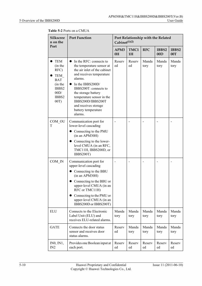
Table 5-2 Ports on a CMUA
Silkscreen on thePort
Port Function Port Relationship with the RelatedCabinet(1)(2)
APM30H
TMC11H
RFC IBBS200D
IBBS200T
l TEM(in theRFC)
l TEM_BAT(in theIBBS200D/IBBS200T)
l In the RFC: connects tothe temperature sensor atthe air inlet of the cabinetand receives temperaturealarms.
l In the IBBS200D/IBBS200T: connects tothe storage batterytemperature sensor in theIBBS200D/IBBS200Tand receives storagebattery temperaturealarms.
Reserved
Reserved
Mandatory
Mandatory
Mandatory
COM_OUT
Communication port forlower-level cascadingl Connecting to the PMU
(in an APM30H)l Connecting to the lower-
level CMUA (in an RFC,TMC11H, IBBS200D, orIBBS200T)
- - - - -
COM_IN Communication port forupper-level cascadingl Connecting to the BBU
(in an APM30H)l Connecting to the BBU or
upper-level CMUA (in anRFC or TMC11H)
l Connecting to the PMU orupper-level CMUA (in anIBBS200D or IBBS200T)
- - - - -
ELU Connects to the ElectronicLabel Unit (ELU) andreceives ELU-related alarms.
Mandatory
Mandatory
Mandatory
Mandatory
Mandatory
GATE Connects the door statussensor and receives doorstatus alarms.
Reserved
Mandatory
Mandatory
Mandatory
Mandatory
IN0, IN1,IN2
Provides one Boolean input ateach port.
Reserved
Reserved
Reserved
Reserved
Reserved
5 Overview of the IBBS200DAPM30H&TMC11H&IBBS200D&IBBS200T(Ver.B)
User Guide
5-10 Huawei Proprietary and ConfidentialCopyright © Huawei Technologies Co., Ltd.
Issue 11 (2011-06-10)

Silkscreen on thePort
Port Function Port Relationship with the RelatedCabinet(1)(2)
APM30H
TMC11H
RFC IBBS200D
IBBS200T
SMOKE Connects to the smoke sensorand receives smoke alarms.
Reserved
Reserved
Reserved
Reserved
Reserved
FAN_EXT
Connects to the outer aircirculation fan on the cabinetand receives alarms related tothe outer air circulation fan.
Mandatory
Mandatory
Reserved
Reserved
Reserved
TECcooler
Connects to the TEC coolerand receives alarms related tothe TEC cooler.
Reserved
Reserved
Reserved
Reserved
Mandatory
l FAN1(in theAPM30H,TMC11H,RFC,orIBBS200D)
l FAN_EXT(in theIBBS200T)
l In the TMC11H orTMC11H: connects to thefan in the fan box.
l In the RFC or IBBS200D:connects to the fan on theright of the fan box.
l In the IBBS200T:connects to the outer aircirculation fan on the TECcooler and receives fan-related alarms fromcabinets.
Mandatory
Mandatory
Mandatory
Mandatory
Mandatory
l FAN2(in theRFCandIBBS200D)
l FAN_INT (intheIBBS200T)
l In the RFC or IBBS200D:connects to the fan on theleft of the fan box.
l In the IBBS200T:connects to the inner aircirculation fan on the TECcooler and receives fan-related alarms fromcabinets.
Reserved
Reserved
Mandatory
Mandatory
Mandatory
PWR CMUA power port - - - - -
APM30H&TMC11H&IBBS200D&IBBS200T(Ver.B)User Guide 5 Overview of the IBBS200D
Issue 11 (2011-06-10) Huawei Proprietary and ConfidentialCopyright © Huawei Technologies Co., Ltd.
5-11
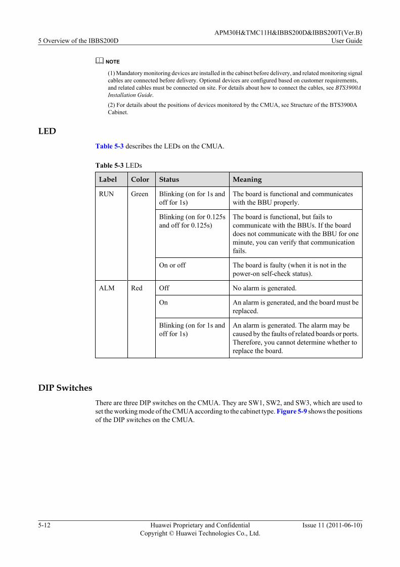
NOTE
(1) Mandatory monitoring devices are installed in the cabinet before delivery, and related monitoring signalcables are connected before delivery. Optional devices are configured based on customer requirements,and related cables must be connected on site. For details about how to connect the cables, see BTS3900AInstallation Guide.
(2) For details about the positions of devices monitored by the CMUA, see Structure of the BTS3900ACabinet.
LEDTable 5-3 describes the LEDs on the CMUA.
Table 5-3 LEDs
Label Color Status Meaning
RUN Green Blinking (on for 1s andoff for 1s)
The board is functional and communicateswith the BBU properly.
Blinking (on for 0.125sand off for 0.125s)
The board is functional, but fails tocommunicate with the BBUs. If the boarddoes not communicate with the BBU for oneminute, you can verify that communicationfails.
On or off The board is faulty (when it is not in thepower-on self-check status).
ALM Red Off No alarm is generated.
On An alarm is generated, and the board must bereplaced.
Blinking (on for 1s andoff for 1s)
An alarm is generated. The alarm may becaused by the faults of related boards or ports.Therefore, you cannot determine whether toreplace the board.
DIP SwitchesThere are three DIP switches on the CMUA. They are SW1, SW2, and SW3, which are used toset the working mode of the CMUA according to the cabinet type. Figure 5-9 shows the positionsof the DIP switches on the CMUA.
5 Overview of the IBBS200DAPM30H&TMC11H&IBBS200D&IBBS200T(Ver.B)
User Guide
5-12 Huawei Proprietary and ConfidentialCopyright © Huawei Technologies Co., Ltd.
Issue 11 (2011-06-10)

Figure 5-9 Positions of the DIP switches on the CMUA (plan view)
The DIP switches in different types of cabinet are set in different modes, as shown in Figure5-10.
Figure 5-10 DIP switch settings of the CMUA in different cabinets
NOTE
The red rectangles in Figure 5-10 show the positions for installing jumper caps.
5.4.4 Storage BatteryThis section provides the exterior of storage batteries and describes technical specifications andconfiguration of storage batteries.
NOTEThe exterior and technical specifications of the storage battery may vary according to manufacturer. Thefollowing description is based on common 12 V 92 Ah storage batteries.
ExteriorFigure 5-11 shows the exterior of the 12 V 92 Ah storage battery.
APM30H&TMC11H&IBBS200D&IBBS200T(Ver.B)User Guide 5 Overview of the IBBS200D
Issue 11 (2011-06-10) Huawei Proprietary and ConfidentialCopyright © Huawei Technologies Co., Ltd.
5-13

Figure 5-11 Exterior of the 12 V 92 Ah storage battery
Technical SpecificationsTable 5-4 describes the technical specifications of the 12 V 92 Ah storage battery.
Table 5-4 Technical specifications of the 12 V 92 Ah storage battery
Type Dimensions (W x H x D) Weight
12 V 92 Ah 105 mm x 287 mm x 390 mm 33.5 kg
108 mm x 287 mm x 393 mm 35 kg
ConfigurationThe cabinet supports two types of storage battery packs: 48 V 92 Ah and 48 V 184 Ah.
l The upper and lower 48 V 92 Ah storage battery packs can be connected in parallel toprovide 48 V 184 Ah power.
l Each storage battery pack contains four single storage batteries.
5.4.5 ELUThe Electronic Label Unit (ELU) automatically reports the information about the cabinet type,facilitating fast troubleshooting.
The ELU is on the left inner side of the IBBS200D or IBBS200T or on the right inner side ofthe APM30H, TMC11H, or RFC. Figure 5-12 shows the ELU.
5 Overview of the IBBS200DAPM30H&TMC11H&IBBS200D&IBBS200T(Ver.B)
User Guide
5-14 Huawei Proprietary and ConfidentialCopyright © Huawei Technologies Co., Ltd.
Issue 11 (2011-06-10)
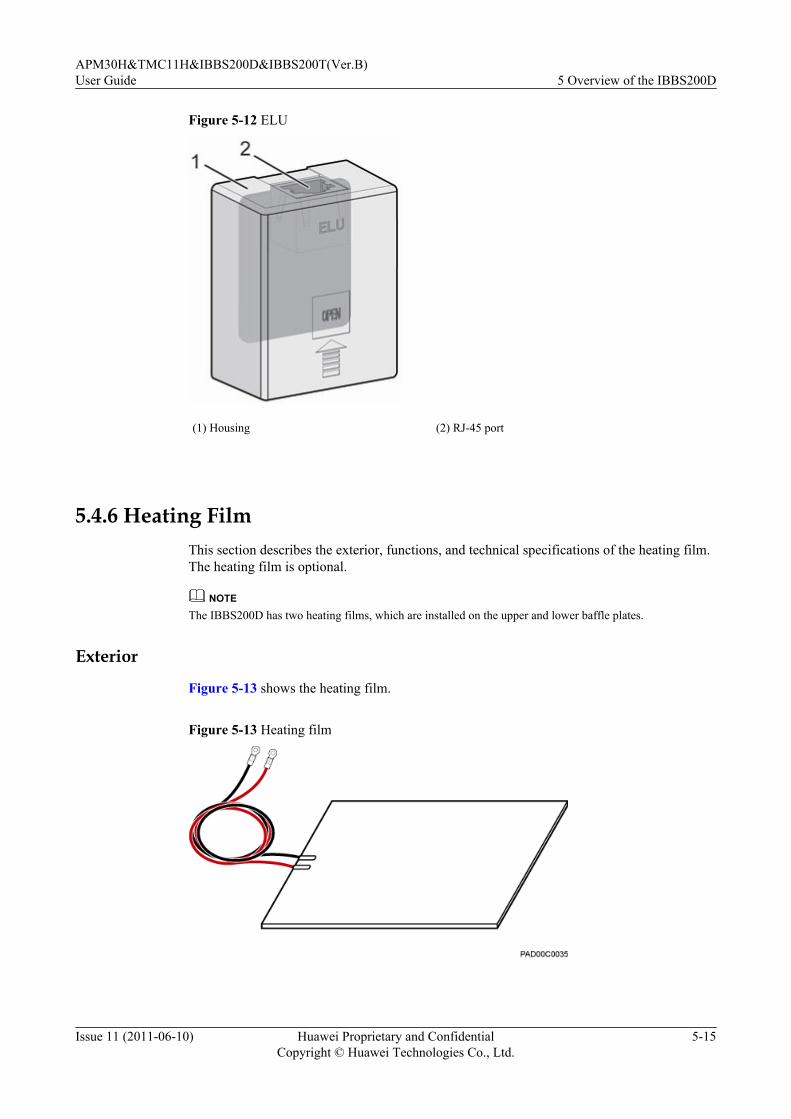
Figure 5-12 ELU
(1) Housing (2) RJ-45 port
5.4.6 Heating FilmThis section describes the exterior, functions, and technical specifications of the heating film.The heating film is optional.
NOTEThe IBBS200D has two heating films, which are installed on the upper and lower baffle plates.
Exterior
Figure 5-13 shows the heating film.
Figure 5-13 Heating film
APM30H&TMC11H&IBBS200D&IBBS200T(Ver.B)User Guide 5 Overview of the IBBS200D
Issue 11 (2011-06-10) Huawei Proprietary and ConfidentialCopyright © Huawei Technologies Co., Ltd.
5-15

Functions
The heating film ensures that the storage batteries are stored and function at the propertemperature when the ambient temperature is low. When the ambient temperature is lower thanthe normal working temperature of the storage battery, the battery capacity decreases. In thiscase, the heating film is required to guarantee the best performance of the storage batteries.
Technical Specifications
The technical specifications of the heating film are as follows:
l The heating film works with the rated voltage of 220 V AC, and the rated heating poweris 100 W.
l When the ambient temperature is lower than +1oC (with ±6oC offset considered), theheating film starts working; when the ambient temperature is higher than 15oC (with±3oC offset considered), the heating film stops working.
5.4.7 Door Status SensorThe door status sensor monitors the opening and closing of the front door of the cabinet.
The door status sensor consists of the magnet part and switch part.
Figure 5-14 shows the magnet part of the door status sensor.
Figure 5-14 Magnet part of the door status sensor
Figure 5-15 shows the switch part of the door status sensor.
5 Overview of the IBBS200DAPM30H&TMC11H&IBBS200D&IBBS200T(Ver.B)
User Guide
5-16 Huawei Proprietary and ConfidentialCopyright © Huawei Technologies Co., Ltd.
Issue 11 (2011-06-10)

Figure 5-15 Switch part of the door status sensor
5.4.8 Temperature Sensor for the Storage BatteriesThe temperature sensor for the storage batteries monitors the temperature in the storage batterycabinet in real time and reports the information to the CMUA.
Installation PositionFigure 5-16 and Figure 5-17 show the installation position of the temperature sensor for thestorage batteries in the IBBS200D and IBBS200T.
Figure 5-16 Installation position of the temperature sensor for the storage batteries in theIBBS200D
APM30H&TMC11H&IBBS200D&IBBS200T(Ver.B)User Guide 5 Overview of the IBBS200D
Issue 11 (2011-06-10) Huawei Proprietary and ConfidentialCopyright © Huawei Technologies Co., Ltd.
5-17

Figure 5-17 Installation position of the temperature sensor for the storage batteries in theIBBS200T
5.5 IBBS200D CablesThe IBBS200D cables consist of the equipotential cable, input power cables for the batteries,power cable for the fans, input power cable for the heating film, and monitoring signal cable.
5.5.1 PGND CableThe PGND cables consist of the PGND cable for the cabinet and PGND cables for the modulesin the cabinet.
5.5.2 Equipotential CableThe equipotential cable connects the PGND terminals of the cabinets, ensuring the equipotentialconnection and safe running of the base station.
5.5.3 Power Cables for the Storage BatteriesThis section describes the input power cables for the storage batteries, power cables betweenthe storage batteries and the copper bar in the junction box, and inter-battery connection copperbar.
5.5.4 Power Cables for the Fans in the IBBS200DThe power cables for the fans in the IBBS200D consist of the input power cable for the fans inthe IBBS200D and the power transfer cable for the fans in the IBBS200D.
5.5.5 Power Cable for the Heating FilmThe power cable for the heating film connects the output terminal on the junction box on the leftof the AMP30H cabinet to the AC power input terminal on the heating film.
5.5.6 ELU Signal CableThe ELU (Electronic Label Unit) signal cable transmits the information about the cabinet typereported by the ELU to the CMUA.
5.5.7 Door Status Monitoring Cable
5 Overview of the IBBS200DAPM30H&TMC11H&IBBS200D&IBBS200T(Ver.B)
User Guide
5-18 Huawei Proprietary and ConfidentialCopyright © Huawei Technologies Co., Ltd.
Issue 11 (2011-06-10)
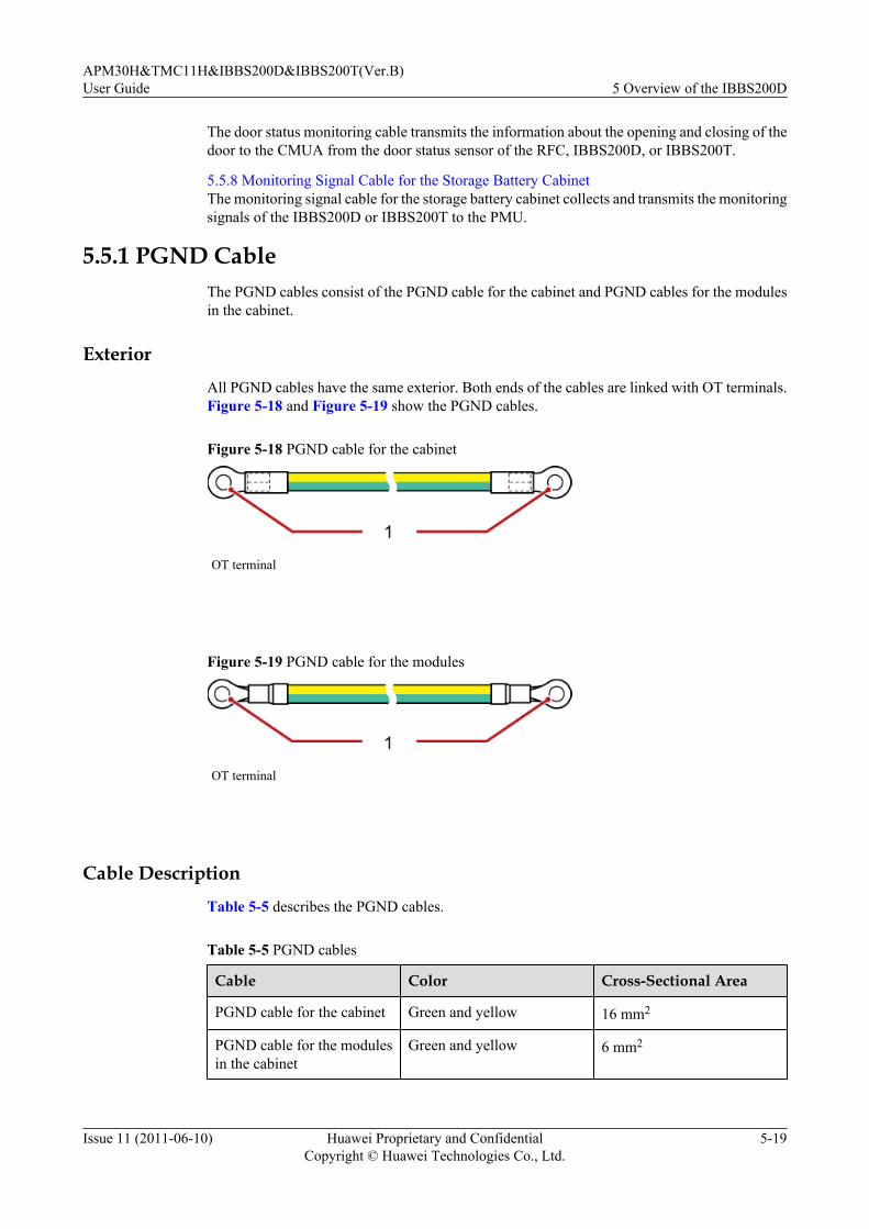
The door status monitoring cable transmits the information about the opening and closing of thedoor to the CMUA from the door status sensor of the RFC, IBBS200D, or IBBS200T.
5.5.8 Monitoring Signal Cable for the Storage Battery CabinetThe monitoring signal cable for the storage battery cabinet collects and transmits the monitoringsignals of the IBBS200D or IBBS200T to the PMU.
5.5.1 PGND CableThe PGND cables consist of the PGND cable for the cabinet and PGND cables for the modulesin the cabinet.
ExteriorAll PGND cables have the same exterior. Both ends of the cables are linked with OT terminals.Figure 5-18 and Figure 5-19 show the PGND cables.
Figure 5-18 PGND cable for the cabinet
OT terminal
Figure 5-19 PGND cable for the modules
OT terminal
Cable DescriptionTable 5-5 describes the PGND cables.
Table 5-5 PGND cables
Cable Color Cross-Sectional Area
PGND cable for the cabinet Green and yellow 16 mm2
PGND cable for the modulesin the cabinet
Green and yellow 6 mm2
APM30H&TMC11H&IBBS200D&IBBS200T(Ver.B)User Guide 5 Overview of the IBBS200D
Issue 11 (2011-06-10) Huawei Proprietary and ConfidentialCopyright © Huawei Technologies Co., Ltd.
5-19
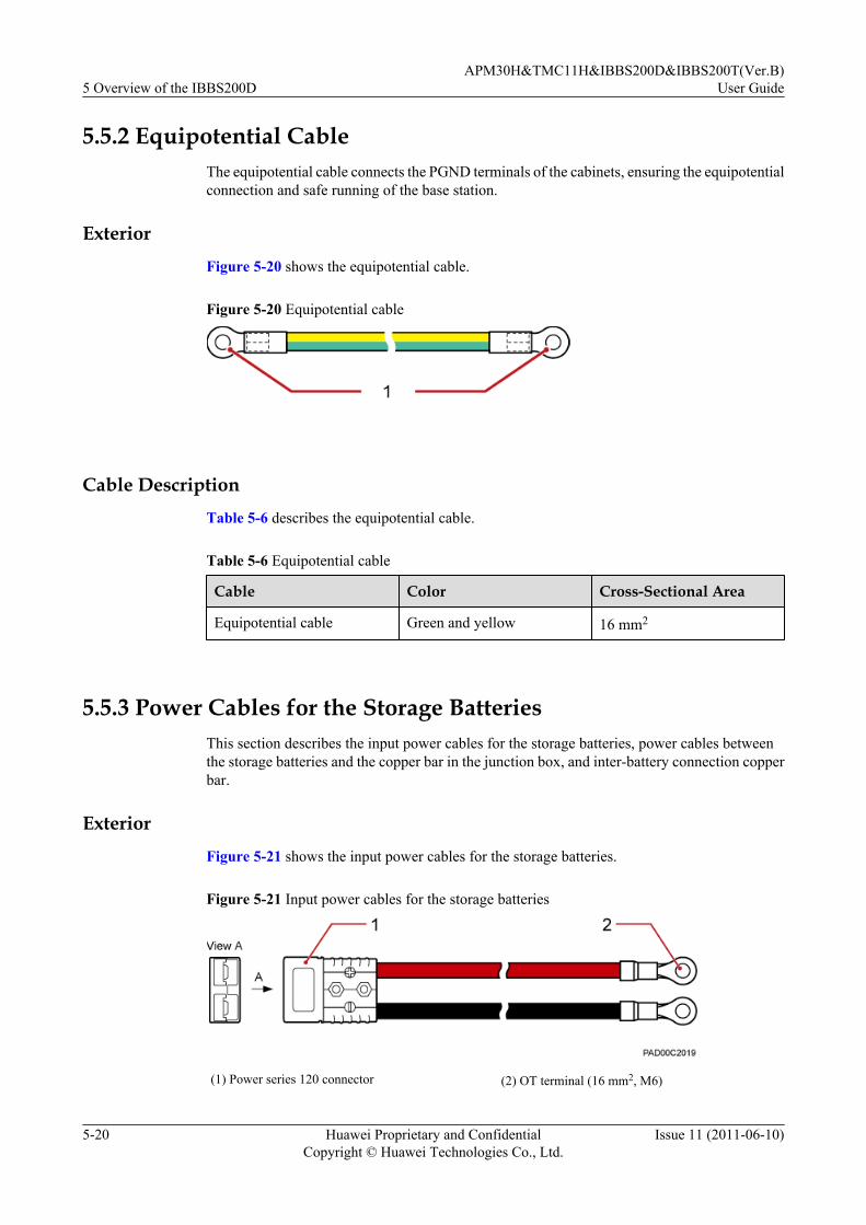
5.5.2 Equipotential CableThe equipotential cable connects the PGND terminals of the cabinets, ensuring the equipotentialconnection and safe running of the base station.
ExteriorFigure 5-20 shows the equipotential cable.
Figure 5-20 Equipotential cable
Cable DescriptionTable 5-6 describes the equipotential cable.
Table 5-6 Equipotential cable
Cable Color Cross-Sectional Area
Equipotential cable Green and yellow 16 mm2
5.5.3 Power Cables for the Storage BatteriesThis section describes the input power cables for the storage batteries, power cables betweenthe storage batteries and the copper bar in the junction box, and inter-battery connection copperbar.
ExteriorFigure 5-21 shows the input power cables for the storage batteries.
Figure 5-21 Input power cables for the storage batteries
(1) Power series 120 connector (2) OT terminal (16 mm2, M6)
5 Overview of the IBBS200DAPM30H&TMC11H&IBBS200D&IBBS200T(Ver.B)
User Guide
5-20 Huawei Proprietary and ConfidentialCopyright © Huawei Technologies Co., Ltd.
Issue 11 (2011-06-10)
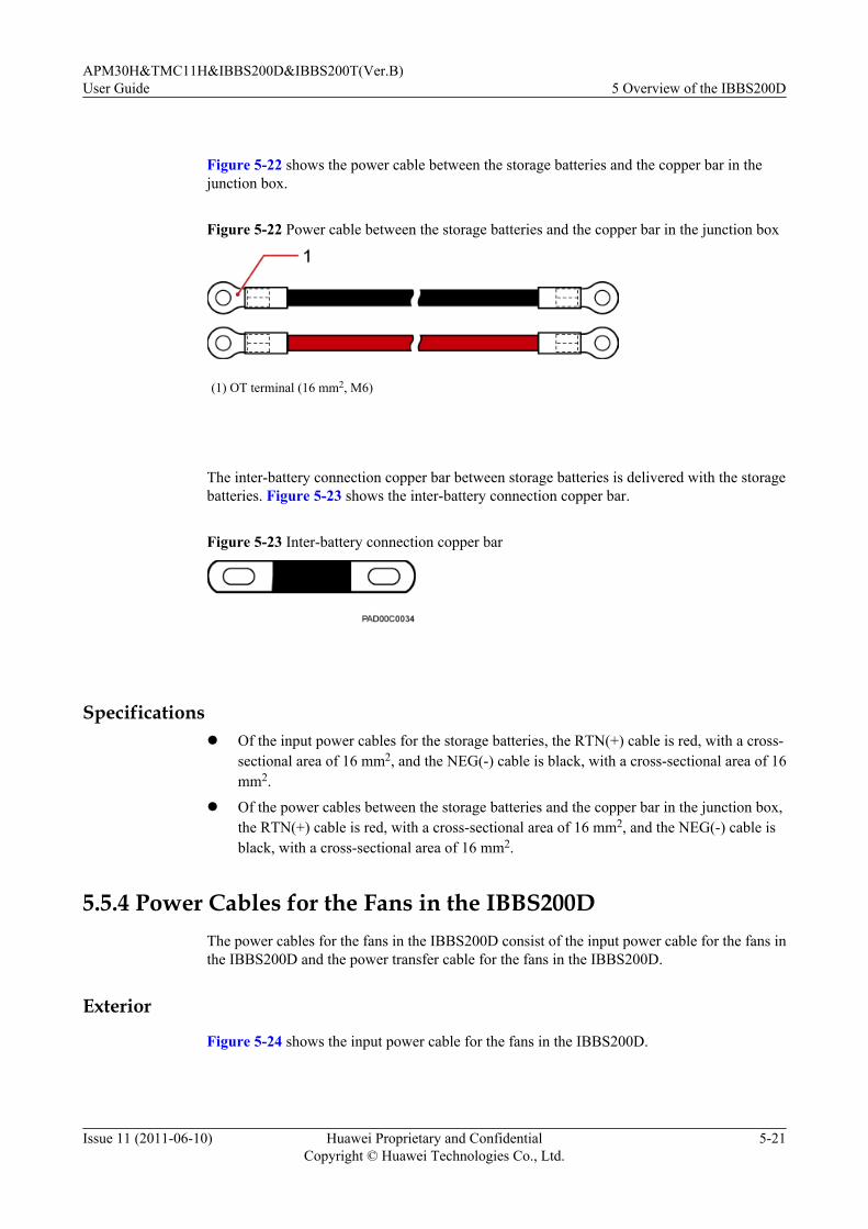
Figure 5-22 shows the power cable between the storage batteries and the copper bar in thejunction box.
Figure 5-22 Power cable between the storage batteries and the copper bar in the junction box
(1) OT terminal (16 mm2, M6)
The inter-battery connection copper bar between storage batteries is delivered with the storagebatteries. Figure 5-23 shows the inter-battery connection copper bar.
Figure 5-23 Inter-battery connection copper bar
Specificationsl Of the input power cables for the storage batteries, the RTN(+) cable is red, with a cross-
sectional area of 16 mm2, and the NEG(-) cable is black, with a cross-sectional area of 16mm2.
l Of the power cables between the storage batteries and the copper bar in the junction box,the RTN(+) cable is red, with a cross-sectional area of 16 mm2, and the NEG(-) cable isblack, with a cross-sectional area of 16 mm2.
5.5.4 Power Cables for the Fans in the IBBS200DThe power cables for the fans in the IBBS200D consist of the input power cable for the fans inthe IBBS200D and the power transfer cable for the fans in the IBBS200D.
Exterior
Figure 5-24 shows the input power cable for the fans in the IBBS200D.
APM30H&TMC11H&IBBS200D&IBBS200T(Ver.B)User Guide 5 Overview of the IBBS200D
Issue 11 (2011-06-10) Huawei Proprietary and ConfidentialCopyright © Huawei Technologies Co., Ltd.
5-21

Figure 5-24 Input power cable for the fans in the IBBS200D
(1) Easy power receptacle (pressfit type) connector (2) OT terminal (2.5 mm2, M4)
Figure 5-25 shows the power transfer cable for the fans in the IBBS200D.
Figure 5-25 Power transfer cable for the fans in the IBBS200D
(1) 3V3 power connector (2) OT terminal (1.5 mm2,M6)
(3) OT terminal (6 mm2,M4)
(4) OT terminal (1.5 mm2,M4)
5.5.5 Power Cable for the Heating FilmThe power cable for the heating film connects the output terminal on the junction box on the leftof the AMP30H cabinet to the AC power input terminal on the heating film.
Exterior
Figure 5-26 shows the power cable for the heating film.
Figure 5-26 Power cable for the heating film
(1) OT terminal (1.5 mm2, M4) for the APM30H cabinet (2) OT terminal (1.5 mm2, M4) for the battery cabinet
5 Overview of the IBBS200DAPM30H&TMC11H&IBBS200D&IBBS200T(Ver.B)
User Guide
5-22 Huawei Proprietary and ConfidentialCopyright © Huawei Technologies Co., Ltd.
Issue 11 (2011-06-10)

Specifications
The AC power cable for the heating film has a cross-sectional area of 1.5 mm2 with a blackjacket. The cable consists of the blue and brown wires.
5.5.6 ELU Signal CableThe ELU (Electronic Label Unit) signal cable transmits the information about the cabinet typereported by the ELU to the CMUA.
Exterior
Figure 5-27 shows the ELU signal cable.
Figure 5-27 ELU signal cable
(1) RJ-45 connector
Pin Assignment
Table 5-7 describes the pin assignment for the wires of the ELU signal cable.
Table 5-7 Pin assignment for the wires of the ELU signal cable
X1 End X2 End Wire Color Type
X1.1 X2.1 White Twisted pair
X1.2 X2.2 Orange
X1.3 X2.3 White Twisted pair
X1.6 X2.6 Green
X1.5 X2.5 White Twisted pair
X1.4 X2.4 Blue
X1.7 X2.7 White Twisted pair
X1.8 X2.8 Brown
APM30H&TMC11H&IBBS200D&IBBS200T(Ver.B)User Guide 5 Overview of the IBBS200D
Issue 11 (2011-06-10) Huawei Proprietary and ConfidentialCopyright © Huawei Technologies Co., Ltd.
5-23

5.5.7 Door Status Monitoring CableThe door status monitoring cable transmits the information about the opening and closing of thedoor to the CMUA from the door status sensor of the RFC, IBBS200D, or IBBS200T.
ExteriorThe door status monitoring cables are two black cables, and both ends of each cable are barewires. Figure 5-28 shows the door status monitoring cable.
Figure 5-28 Door status monitoring cable
5.5.8 Monitoring Signal Cable for the Storage Battery CabinetThe monitoring signal cable for the storage battery cabinet collects and transmits the monitoringsignals of the IBBS200D or IBBS200T to the PMU.
ExteriorFigure 5-29 shows the monitoring signal cable for the storage battery cabinet.
Figure 5-29 Monitoring signal cable for the storage battery cabinet
(1) RJ45 connector
Pin AssignmentTable 5-8 describes the pin assignment for the wires of the monitoring signal cable for the storagebattery cabinet.
Table 5-8 Pin assignment for the wires of the monitoring signal cable for the storage batterycabinet
X1 End X2 End Wire Color Type
X1.1 X2.1 White Twisted pair
X1.2 X2.2 Orange
5 Overview of the IBBS200DAPM30H&TMC11H&IBBS200D&IBBS200T(Ver.B)
User Guide
5-24 Huawei Proprietary and ConfidentialCopyright © Huawei Technologies Co., Ltd.
Issue 11 (2011-06-10)

X1 End X2 End Wire Color Type
X1.3 X2.3 White Twisted pair
X1.6 X2.6 Green
X1.5 X2.5 White Twisted pair
X1.4 X2.4 Blue
X1.7 X2.7 White Twisted pair
X1.8 X2.8 Brown
APM30H&TMC11H&IBBS200D&IBBS200T(Ver.B)User Guide 5 Overview of the IBBS200D
Issue 11 (2011-06-10) Huawei Proprietary and ConfidentialCopyright © Huawei Technologies Co., Ltd.
5-25

6 Overview of the TMC11H
About This Chapter
This describes the exterior, structure, components, and cables of the TMC11H.
6.1 Exterior of the TMC11HThe TMC11H is elegantly designed. It is small in size and easy to transport.
6.2 Structure of the TMC11HThe TMC11H has a highly integrated and modular structure design. Thus, the cabinet is easy tooperate and maintain.
6.3 Cable Connections of the TMC11HThe cables of the TMC11H are power cables and signal cables.
6.4 TMC11H ComponentsThe components of the TMC11H consist of the fan box, DCDU-03, and heater. The heater isoptional.
6.5 TMC11H CablesThe TMC11H cables consist of the equipotential cable, input power cable, power cable for thefan box, ELU signal cable, signal cables between the CMUA and the door status sensor, andtransfer cable for the fan on the front door.
APM30H&TMC11H&IBBS200D&IBBS200T(Ver.B)User Guide 6 Overview of the TMC11H
Issue 11 (2011-06-10) Huawei Proprietary and ConfidentialCopyright © Huawei Technologies Co., Ltd.
6-1

6.1 Exterior of the TMC11HThe TMC11H is elegantly designed. It is small in size and easy to transport.
Figure 6-1 shows the TMC11H.
Figure 6-1 TMC11H
6.2 Structure of the TMC11HThe TMC11H has a highly integrated and modular structure design. Thus, the cabinet is easy tooperate and maintain.
Figure 6-2 shows the internal structure of the TMC11H.
6 Overview of the TMC11HAPM30H&TMC11H&IBBS200D&IBBS200T(Ver.B)
User Guide
6-2 Huawei Proprietary and ConfidentialCopyright © Huawei Technologies Co., Ltd.
Issue 11 (2011-06-10)

Figure 6-2 Internal structure of the TMC11H
(1) Inner air circulation fan (2) CMUA (3) DCDU-03
(4) ELU (5) Door status sensor (6) Outer air circulation fan
(7) Heat exchanger (8) Junction box -
The TMC11H has the following features with regard to its structure:l If the heater is not installed, the TMC11H provides a 11 U space for user equipment.l The heater should be installed in the 1 U space at the bottom of the TMC11H.l The TMC11H provides a 1 U space at the top for operation and maintenance of the fan box.
6.3 Cable Connections of the TMC11HThe cables of the TMC11H are power cables and signal cables.
Figure 6-3 shows the cable connection of the TMC11H.
APM30H&TMC11H&IBBS200D&IBBS200T(Ver.B)User Guide 6 Overview of the TMC11H
Issue 11 (2011-06-10) Huawei Proprietary and ConfidentialCopyright © Huawei Technologies Co., Ltd.
6-3

Figure 6-3 Cable connections of the TMC11H
(1) Power transfer cable for theheater
(2) 6.5.2 Input Power Cable for theTMC11H
(3) 6.5.5 Door Status MonitoringCable
(4) 6.5.4 ELU Signal Cable (5) 6.5.3 Power Cable for the FanBox in the TMC11H
-
6.4 TMC11H ComponentsThe components of the TMC11H consist of the fan box, DCDU-03, and heater. The heater isoptional.
6.4.1 Fan BoxThe fan box consists of the fan subrack, fans, HPMI, and CMUA.
6.4.2 DCDU-03The Direct Current Distribution Unit-03 (DCDU-03) supplies DC power to each component inthe cabinet. The height of the DCDU-03 is 1 U. It can be classified into the DCDU-03B andDCDU-03C according to the configured MCBs and application scenarios. The two models havethe same exterior and engineering specifications.
6.4.3 Core of the Heat ExchangerThe core of the heat exchanger extends the area for the exchange of the air inside and outsidethe cabinet, speeding up the air circulation and effectively decreasing the working temperatureof the cabinet. In addition, the core of the heat exchanger keeps the dust away from the cabinet.
6.4.4 Junction BoxThe junction box divides one AC input into four AC outputs. The AC outputs are used for theSOU and multiple heating films or heaters.
6 Overview of the TMC11HAPM30H&TMC11H&IBBS200D&IBBS200T(Ver.B)
User Guide
6-4 Huawei Proprietary and ConfidentialCopyright © Huawei Technologies Co., Ltd.
Issue 11 (2011-06-10)
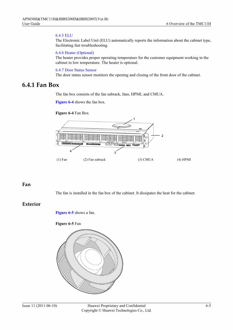
6.4.5 ELUThe Electronic Label Unit (ELU) automatically reports the information about the cabinet type,facilitating fast troubleshooting.
6.4.6 Heater (Optional)The heater provides proper operating temperature for the customer equipment working in thecabinet in low temperature. The heater is optional.
6.4.7 Door Status SensorThe door status sensor monitors the opening and closing of the front door of the cabinet.
6.4.1 Fan BoxThe fan box consists of the fan subrack, fans, HPMI, and CMUA.
Figure 6-4 shows the fan box.
Figure 6-4 Fan Box
(1) Fan (2) Fan subrack (3) CMUA (4) HPMI
FanThe fan is installed in the fan box of the cabinet. It dissipates the heat for the cabinet.
ExteriorFigure 6-5 shows a fan.
Figure 6-5 Fan
APM30H&TMC11H&IBBS200D&IBBS200T(Ver.B)User Guide 6 Overview of the TMC11H
Issue 11 (2011-06-10) Huawei Proprietary and ConfidentialCopyright © Huawei Technologies Co., Ltd.
6-5
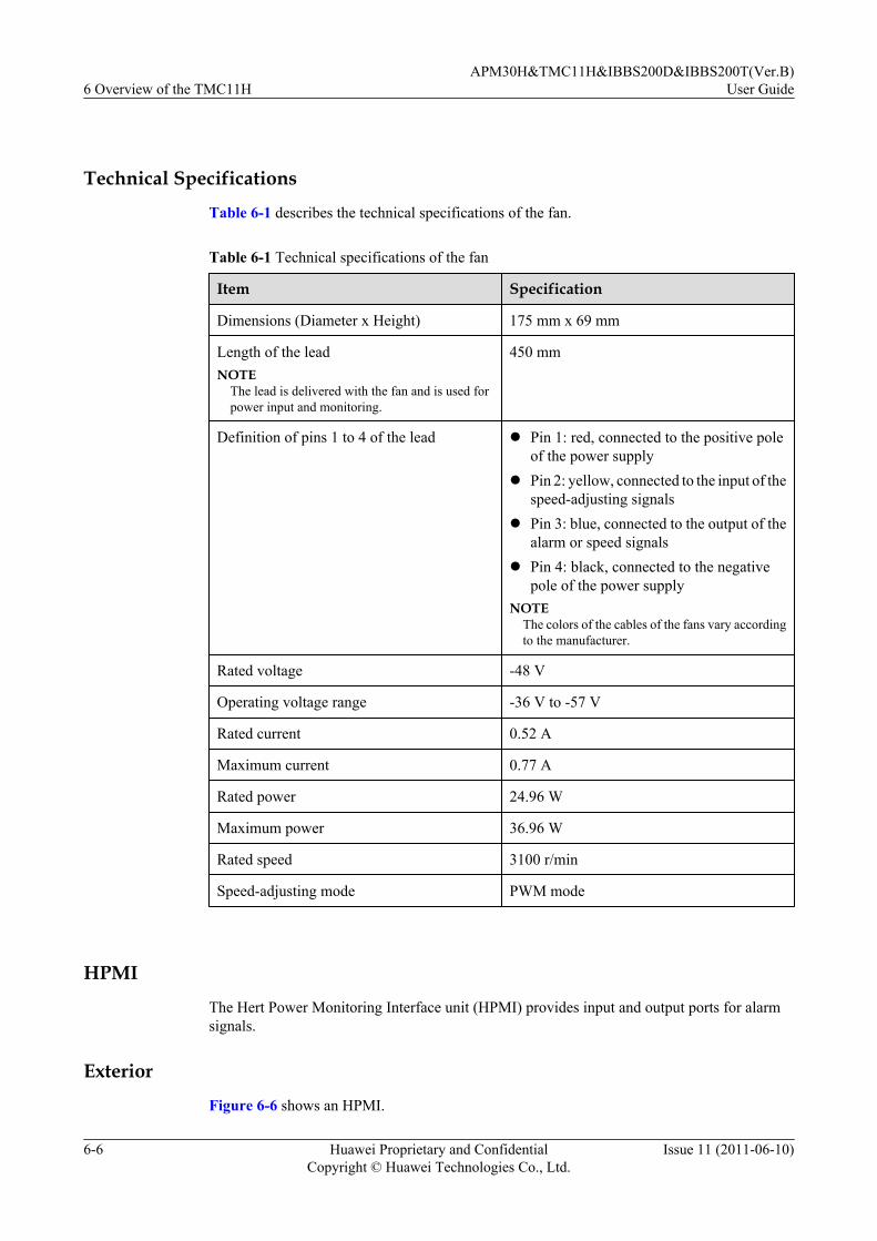
Technical Specifications
Table 6-1 describes the technical specifications of the fan.
Table 6-1 Technical specifications of the fan
Item Specification
Dimensions (Diameter x Height) 175 mm x 69 mm
Length of the leadNOTE
The lead is delivered with the fan and is used forpower input and monitoring.
450 mm
Definition of pins 1 to 4 of the lead l Pin 1: red, connected to the positive poleof the power supply
l Pin 2: yellow, connected to the input of thespeed-adjusting signals
l Pin 3: blue, connected to the output of thealarm or speed signals
l Pin 4: black, connected to the negativepole of the power supply
NOTEThe colors of the cables of the fans vary accordingto the manufacturer.
Rated voltage -48 V
Operating voltage range -36 V to -57 V
Rated current 0.52 A
Maximum current 0.77 A
Rated power 24.96 W
Maximum power 36.96 W
Rated speed 3100 r/min
Speed-adjusting mode PWM mode
HPMI
The Hert Power Monitoring Interface unit (HPMI) provides input and output ports for alarmsignals.
Exterior
Figure 6-6 shows an HPMI.
6 Overview of the TMC11HAPM30H&TMC11H&IBBS200D&IBBS200T(Ver.B)
User Guide
6-6 Huawei Proprietary and ConfidentialCopyright © Huawei Technologies Co., Ltd.
Issue 11 (2011-06-10)
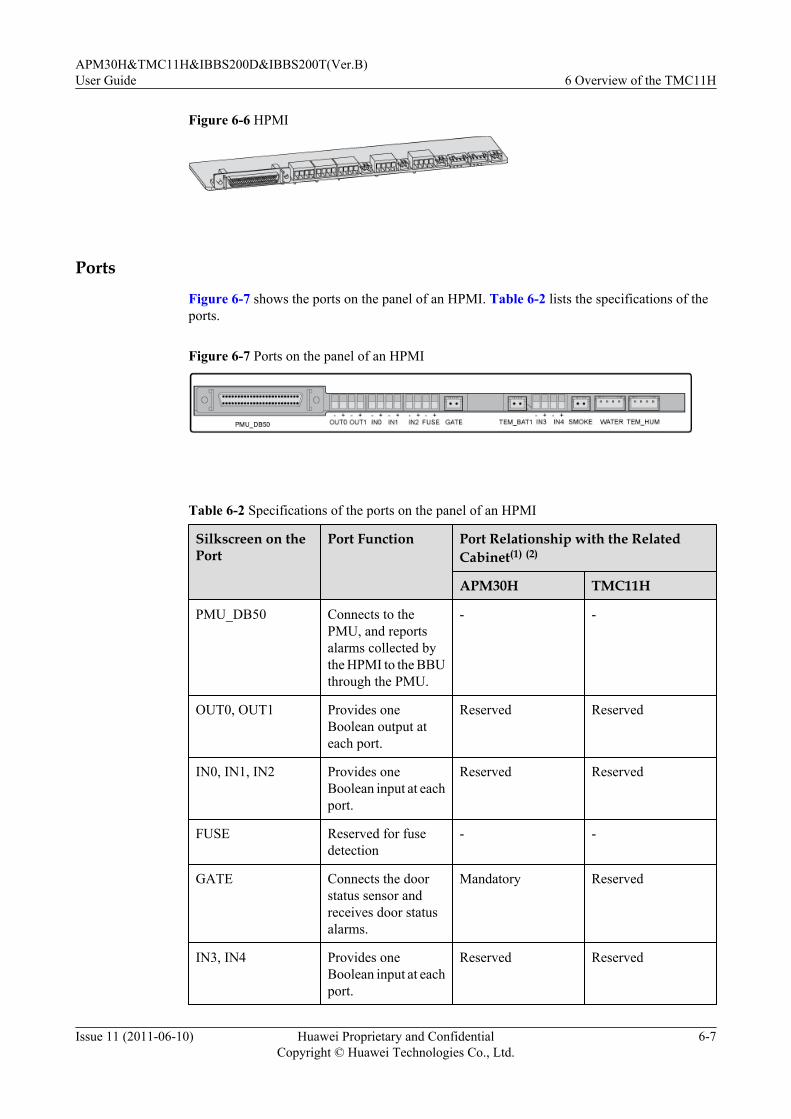
Figure 6-6 HPMI
Ports
Figure 6-7 shows the ports on the panel of an HPMI. Table 6-2 lists the specifications of theports.
Figure 6-7 Ports on the panel of an HPMI
Table 6-2 Specifications of the ports on the panel of an HPMI
Silkscreen on thePort
Port Function Port Relationship with the RelatedCabinet(1) (2)
APM30H TMC11H
PMU_DB50 Connects to thePMU, and reportsalarms collected bythe HPMI to the BBUthrough the PMU.
- -
OUT0, OUT1 Provides oneBoolean output ateach port.
Reserved Reserved
IN0, IN1, IN2 Provides oneBoolean input at eachport.
Reserved Reserved
FUSE Reserved for fusedetection
- -
GATE Connects the doorstatus sensor andreceives door statusalarms.
Mandatory Reserved
IN3, IN4 Provides oneBoolean input at eachport.
Reserved Reserved
APM30H&TMC11H&IBBS200D&IBBS200T(Ver.B)User Guide 6 Overview of the TMC11H
Issue 11 (2011-06-10) Huawei Proprietary and ConfidentialCopyright © Huawei Technologies Co., Ltd.
6-7

Silkscreen on thePort
Port Function Port Relationship with the RelatedCabinet(1) (2)
APM30H TMC11H
TEM_BAT1 Connects to thestorage batterytemperature sensor inIBBS2.1 andIBBS2.2 andreceives storagebattery temperaturealarms.
Optional Reserved
SMOKE Connects the smokesensor and receivessmoke alarms.
Reserved Reserved
WATER Connects the watersensor and receiveswater damagealarms.
Reserved Reserved
TEM_HUM Connects to thetemperature andhumidity sensor andreceives temperatureand humidity alarms.
Reserved Reserved
NOTE
(1) Mandatory monitoring devices are installed in the cabinet before delivery, and related monitoring signalcables are connected before delivery. Optional devices are configured based on customer requirements,and related cables must be connected on site. For details about how to connect the cables, see BTS3900AInstallation Guide.
(2) For details about the positions of devices monitored by the HPMI, see Structure of the BTS3900ACabinet.
CMUAThis section describes the central monitoring unit type A (CMUA).
FunctionsThe CMUA has the following functions:
l Adjusts and controls temperature of the cabinet in different temperature control modes.l Reserves a port for three Boolean inputs and detects Boolean alarms in the cabinet. The
remote detection, however, is not supported.l Provides a port for the RJ45 connector to enable electronic label and cabinet type detection.
6 Overview of the TMC11HAPM30H&TMC11H&IBBS200D&IBBS200T(Ver.B)
User Guide
6-8 Huawei Proprietary and ConfidentialCopyright © Huawei Technologies Co., Ltd.
Issue 11 (2011-06-10)

ExteriorFigure 6-8 shows a CMUA.
Figure 6-8 CMUA
PortsFigure 6-9 shows the ports on the CMUA, and Table 6-3 describes the ports.
Figure 6-9 Ports on a CMUA (plan view)
APM30H&TMC11H&IBBS200D&IBBS200T(Ver.B)User Guide 6 Overview of the TMC11H
Issue 11 (2011-06-10) Huawei Proprietary and ConfidentialCopyright © Huawei Technologies Co., Ltd.
6-9

Table 6-3 Ports on a CMUA
Silkscreen on thePort
Port Function Port Relationship with the RelatedCabinet(1)(2)
APM30H
TMC11H
RFC IBBS200D
IBBS200T
l TEM(in theRFC)
l TEM_BAT(in theIBBS200D/IBBS200T)
l In the RFC: connects tothe temperature sensor atthe air inlet of the cabinetand receives temperaturealarms.
l In the IBBS200D/IBBS200T: connects tothe storage batterytemperature sensor in theIBBS200D/IBBS200Tand receives storagebattery temperaturealarms.
Reserved
Reserved
Mandatory
Mandatory
Mandatory
COM_OUT
Communication port forlower-level cascadingl Connecting to the PMU
(in an APM30H)l Connecting to the lower-
level CMUA (in an RFC,TMC11H, IBBS200D, orIBBS200T)
- - - - -
COM_IN Communication port forupper-level cascadingl Connecting to the BBU
(in an APM30H)l Connecting to the BBU or
upper-level CMUA (in anRFC or TMC11H)
l Connecting to the PMU orupper-level CMUA (in anIBBS200D or IBBS200T)
- - - - -
ELU Connects to the ElectronicLabel Unit (ELU) andreceives ELU-related alarms.
Mandatory
Mandatory
Mandatory
Mandatory
Mandatory
GATE Connects the door statussensor and receives doorstatus alarms.
Reserved
Mandatory
Mandatory
Mandatory
Mandatory
IN0, IN1,IN2
Provides one Boolean input ateach port.
Reserved
Reserved
Reserved
Reserved
Reserved
6 Overview of the TMC11HAPM30H&TMC11H&IBBS200D&IBBS200T(Ver.B)
User Guide
6-10 Huawei Proprietary and ConfidentialCopyright © Huawei Technologies Co., Ltd.
Issue 11 (2011-06-10)
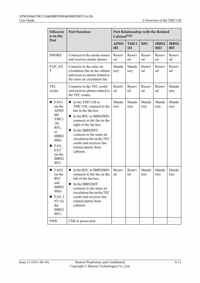
Silkscreen on thePort
Port Function Port Relationship with the RelatedCabinet(1)(2)
APM30H
TMC11H
RFC IBBS200D
IBBS200T
SMOKE Connects to the smoke sensorand receives smoke alarms.
Reserved
Reserved
Reserved
Reserved
Reserved
FAN_EXT
Connects to the outer aircirculation fan on the cabinetand receives alarms related tothe outer air circulation fan.
Mandatory
Mandatory
Reserved
Reserved
Reserved
TECcooler
Connects to the TEC coolerand receives alarms related tothe TEC cooler.
Reserved
Reserved
Reserved
Reserved
Mandatory
l FAN1(in theAPM30H,TMC11H,RFC,orIBBS200D)
l FAN_EXT(in theIBBS200T)
l In the TMC11H orTMC11H: connects to thefan in the fan box.
l In the RFC or IBBS200D:connects to the fan on theright of the fan box.
l In the IBBS200T:connects to the outer aircirculation fan on the TECcooler and receives fan-related alarms fromcabinets.
Mandatory
Mandatory
Mandatory
Mandatory
Mandatory
l FAN2(in theRFCandIBBS200D)
l FAN_INT (intheIBBS200T)
l In the RFC or IBBS200D:connects to the fan on theleft of the fan box.
l In the IBBS200T:connects to the inner aircirculation fan on the TECcooler and receives fan-related alarms fromcabinets.
Reserved
Reserved
Mandatory
Mandatory
Mandatory
PWR CMUA power port - - - - -
APM30H&TMC11H&IBBS200D&IBBS200T(Ver.B)User Guide 6 Overview of the TMC11H
Issue 11 (2011-06-10) Huawei Proprietary and ConfidentialCopyright © Huawei Technologies Co., Ltd.
6-11
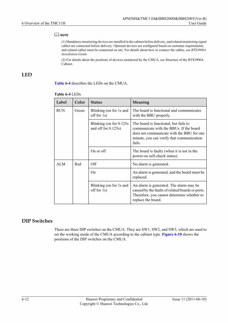
NOTE
(1) Mandatory monitoring devices are installed in the cabinet before delivery, and related monitoring signalcables are connected before delivery. Optional devices are configured based on customer requirements,and related cables must be connected on site. For details about how to connect the cables, see BTS3900AInstallation Guide.
(2) For details about the positions of devices monitored by the CMUA, see Structure of the BTS3900ACabinet.
LEDTable 6-4 describes the LEDs on the CMUA.
Table 6-4 LEDs
Label Color Status Meaning
RUN Green Blinking (on for 1s andoff for 1s)
The board is functional and communicateswith the BBU properly.
Blinking (on for 0.125sand off for 0.125s)
The board is functional, but fails tocommunicate with the BBUs. If the boarddoes not communicate with the BBU for oneminute, you can verify that communicationfails.
On or off The board is faulty (when it is not in thepower-on self-check status).
ALM Red Off No alarm is generated.
On An alarm is generated, and the board must bereplaced.
Blinking (on for 1s andoff for 1s)
An alarm is generated. The alarm may becaused by the faults of related boards or ports.Therefore, you cannot determine whether toreplace the board.
DIP SwitchesThere are three DIP switches on the CMUA. They are SW1, SW2, and SW3, which are used toset the working mode of the CMUA according to the cabinet type. Figure 6-10 shows thepositions of the DIP switches on the CMUA.
6 Overview of the TMC11HAPM30H&TMC11H&IBBS200D&IBBS200T(Ver.B)
User Guide
6-12 Huawei Proprietary and ConfidentialCopyright © Huawei Technologies Co., Ltd.
Issue 11 (2011-06-10)
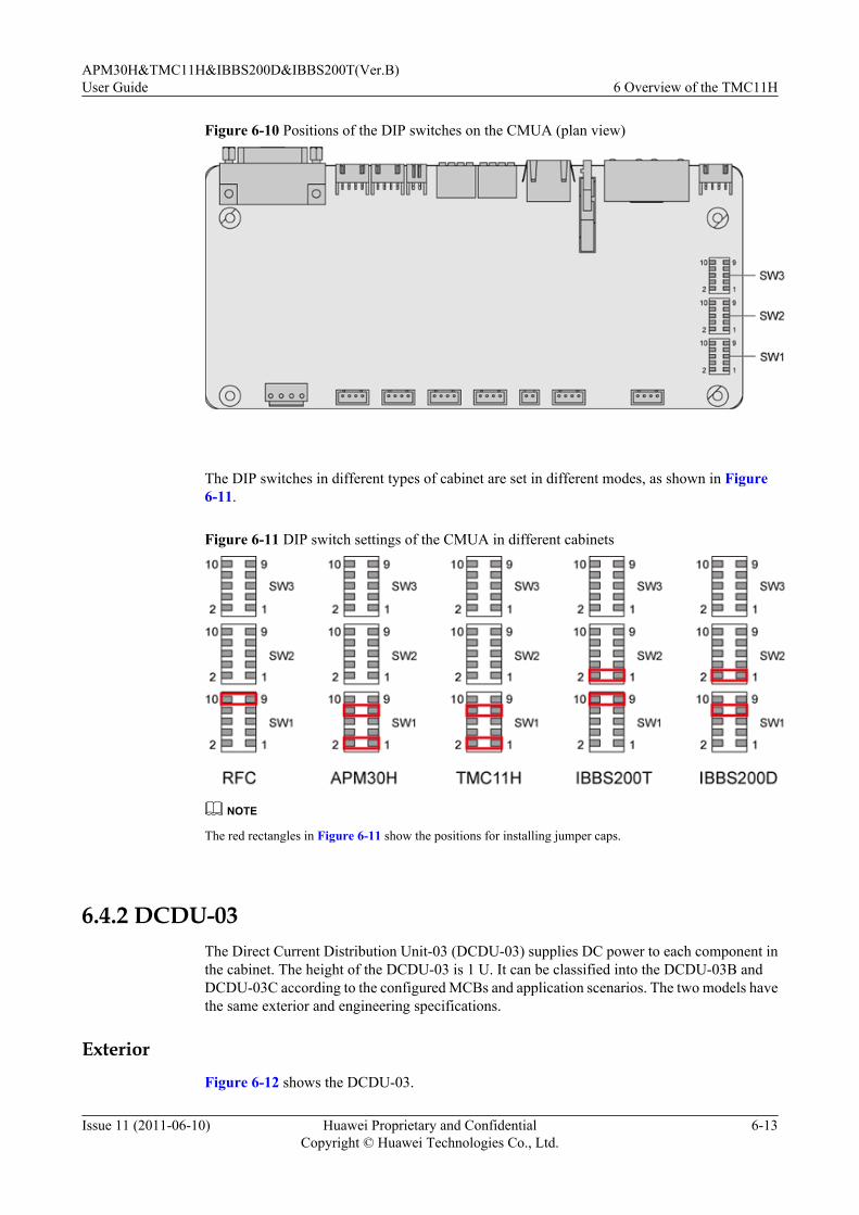
Figure 6-10 Positions of the DIP switches on the CMUA (plan view)
The DIP switches in different types of cabinet are set in different modes, as shown in Figure6-11.
Figure 6-11 DIP switch settings of the CMUA in different cabinets
NOTE
The red rectangles in Figure 6-11 show the positions for installing jumper caps.
6.4.2 DCDU-03The Direct Current Distribution Unit-03 (DCDU-03) supplies DC power to each component inthe cabinet. The height of the DCDU-03 is 1 U. It can be classified into the DCDU-03B andDCDU-03C according to the configured MCBs and application scenarios. The two models havethe same exterior and engineering specifications.
ExteriorFigure 6-12 shows the DCDU-03.
APM30H&TMC11H&IBBS200D&IBBS200T(Ver.B)User Guide 6 Overview of the TMC11H
Issue 11 (2011-06-10) Huawei Proprietary and ConfidentialCopyright © Huawei Technologies Co., Ltd.
6-13

Figure 6-12 DCDU-03
Functions
The DCDU-03 provides nine -48 V DC outputs and different MCB configurations to meet thepower distribution requirements of the scenarios of distributed and separated base stations.
Table 6-5 describes the DC power distribution functions of the DCDU-03.
Table 6-5 DC power distribution functions of the DCDU-03
DCDUModel
DC OutputTerminal
PowerConsumptionEquipment
MCBSpecification
MCBQuantity
Application Scenario
DCDU-03B LOAD0 toLOAD5
RRU 20 A 6 Distributedbase station/Mini basestationLOAD6 to
LOAD8BBU and thetransmissionequipment ofthe customer
12 A 3
DCDU-03C LOAD0 toLOAD5
Transmission equipmentof thecustomer
12 A 6 Separatedmacro basestation in the-48 V DCpowersupply/Transmission cabinet
LOAD6 BBU 12 A 1
LOAD7 Transmission equipmentof thecustomer
6 A 1
LOAD8 Fan box 6 A 1
6 Overview of the TMC11HAPM30H&TMC11H&IBBS200D&IBBS200T(Ver.B)
User Guide
6-14 Huawei Proprietary and ConfidentialCopyright © Huawei Technologies Co., Ltd.
Issue 11 (2011-06-10)
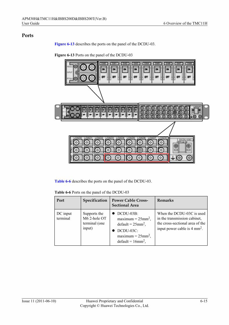
PortsFigure 6-13 describes the ports on the panel of the DCDU-03.
Figure 6-13 Ports on the panel of the DCDU-03
Table 6-6 describes the ports on the panel of the DCDU-03.
Table 6-6 Ports on the panel of the DCDU-03
Port Specification Power Cable Cross-Sectional Area
Remarks
DC inputterminal
Supports theM6 2-hole OTterminal (oneinput)
l DCDU-03B:maximum = 25mm2,default = 25mm2,
l DCDU-03C:maximum = 25mm2,default = 16mm2,
When the DCDU-03C is usedin the transmission cabinet,the cross-sectional area of theinput power cable is 4 mm2.
APM30H&TMC11H&IBBS200D&IBBS200T(Ver.B)User Guide 6 Overview of the TMC11H
Issue 11 (2011-06-10) Huawei Proprietary and ConfidentialCopyright © Huawei Technologies Co., Ltd.
6-15
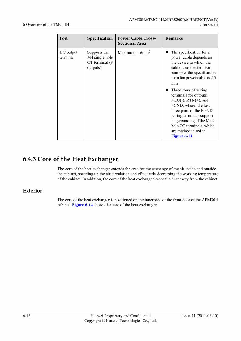
Port Specification Power Cable Cross-Sectional Area
Remarks
DC outputterminal
Supports theM4 single holeOT terminal (9outputs)
Maximum = 6mm2 l The specification for apower cable depends onthe device to which thecable is connected. Forexample, the specificationfor a fan power cable is 2.5mm2.
l Three rows of wiringterminals for outputs:NEG(-), RTN(+), andPGND, where, the lastthree pairs of the PGNDwiring terminals supportthe grounding of the M4 2-hole OT terminals, whichare marked in red inFigure 6-13
6.4.3 Core of the Heat ExchangerThe core of the heat exchanger extends the area for the exchange of the air inside and outsidethe cabinet, speeding up the air circulation and effectively decreasing the working temperatureof the cabinet. In addition, the core of the heat exchanger keeps the dust away from the cabinet.
ExteriorThe core of the heat exchanger is positioned on the inner side of the front door of the APM30Hcabinet. Figure 6-14 shows the core of the heat exchanger.
6 Overview of the TMC11HAPM30H&TMC11H&IBBS200D&IBBS200T(Ver.B)
User Guide
6-16 Huawei Proprietary and ConfidentialCopyright © Huawei Technologies Co., Ltd.
Issue 11 (2011-06-10)
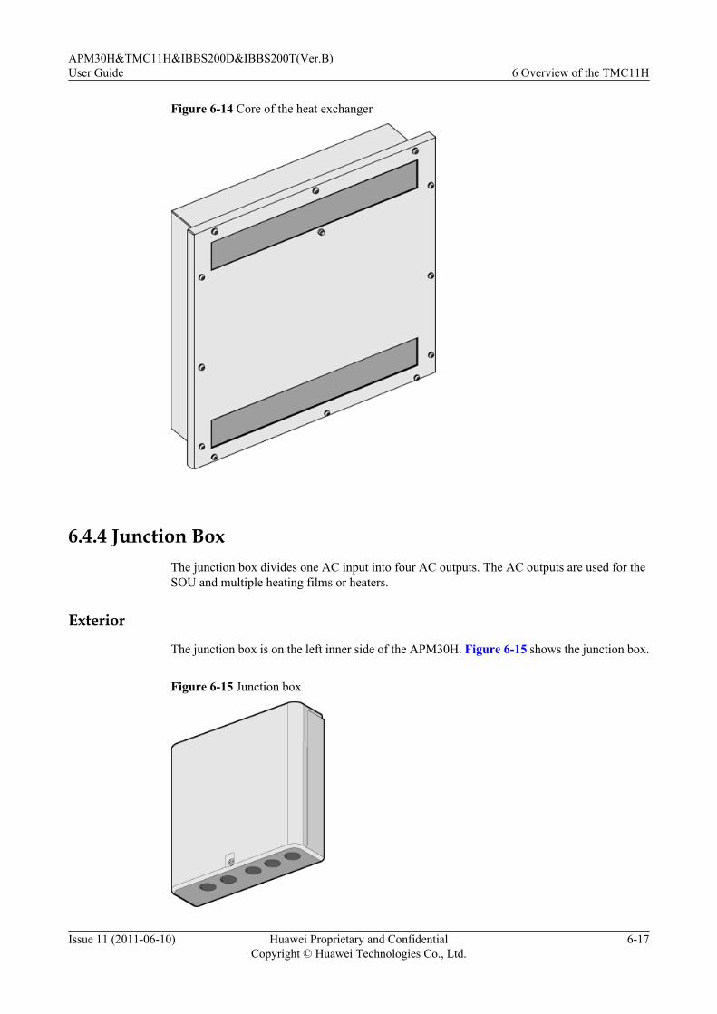
Figure 6-14 Core of the heat exchanger
6.4.4 Junction BoxThe junction box divides one AC input into four AC outputs. The AC outputs are used for theSOU and multiple heating films or heaters.
Exterior
The junction box is on the left inner side of the APM30H. Figure 6-15 shows the junction box.
Figure 6-15 Junction box
APM30H&TMC11H&IBBS200D&IBBS200T(Ver.B)User Guide 6 Overview of the TMC11H
Issue 11 (2011-06-10) Huawei Proprietary and ConfidentialCopyright © Huawei Technologies Co., Ltd.
6-17

StructureFigure 6-16 shows the structure of the junction box.
Figure 6-16 Structure of the junction box
(1) L wiring terminals for four ACoutputs
(2) N wiring terminals for four ACoutputs
(3) PE wiring terminals for four ACoutputs
(4) Cable holes (5) N wiring terminals for the ACinput
(6) L wiring terminal for the ACinput
6.4.5 ELUThe Electronic Label Unit (ELU) automatically reports the information about the cabinet type,facilitating fast troubleshooting.
The ELU is on the left inner side of the IBBS200D or IBBS200T or on the right inner side ofthe APM30H, TMC11H, or RFC. Figure 6-17 shows the ELU.
6 Overview of the TMC11HAPM30H&TMC11H&IBBS200D&IBBS200T(Ver.B)
User Guide
6-18 Huawei Proprietary and ConfidentialCopyright © Huawei Technologies Co., Ltd.
Issue 11 (2011-06-10)

Figure 6-17 ELU
(1) Housing (2) RJ-45 port
6.4.6 Heater (Optional)The heater provides proper operating temperature for the customer equipment working in thecabinet in low temperature. The heater is optional.
ExteriorThe heater is 1 U high. Figure 6-18 shows the heater.
Figure 6-18 Heater
Technical SpecificationsThe technical specifications of the heater are as follows:
l When the temperature in the cabinet is lower than +1oC (with ±6oC offset considered), theheater starts working. When the temperature in the cabinet is higher than +15oC (with±3oC offset considered), the heater stops working.
l The rated heating power of the heater is 330 W.
APM30H&TMC11H&IBBS200D&IBBS200T(Ver.B)User Guide 6 Overview of the TMC11H
Issue 11 (2011-06-10) Huawei Proprietary and ConfidentialCopyright © Huawei Technologies Co., Ltd.
6-19

6.4.7 Door Status SensorThe door status sensor monitors the opening and closing of the front door of the cabinet.
The door status sensor consists of the magnet part and switch part.
Figure 6-19 shows the magnet part of the door status sensor.
Figure 6-19 Magnet part of the door status sensor
Figure 6-20 shows the switch part of the door status sensor.
Figure 6-20 Switch part of the door status sensor
6 Overview of the TMC11HAPM30H&TMC11H&IBBS200D&IBBS200T(Ver.B)
User Guide
6-20 Huawei Proprietary and ConfidentialCopyright © Huawei Technologies Co., Ltd.
Issue 11 (2011-06-10)

6.5 TMC11H CablesThe TMC11H cables consist of the equipotential cable, input power cable, power cable for thefan box, ELU signal cable, signal cables between the CMUA and the door status sensor, andtransfer cable for the fan on the front door.
6.5.1 Equipotential CableThe equipotential cable connects the PGND terminals of the cabinets, ensuring the equipotentialconnection and safe running of the base station.
6.5.2 Input Power Cable for the TMC11HThe input power cable for the TMC11H varies according to the power supply scenario.
6.5.3 Power Cable for the Fan Box in the TMC11HThe power cable feeds -48 V DC power cable into the fan box in the transmission cabinet fromthe DCDU-03.
6.5.4 ELU Signal CableThe ELU (Electronic Label Unit) signal cable transmits the information about the cabinet typereported by the ELU to the CMUA.
6.5.5 Door Status Monitoring CableThe door status monitoring cable transmits the information about the opening and closing of thedoor to the CMUA from the door status sensor of the RFC, IBBS200D, or IBBS200T.
6.5.6 Monitoring Signal Cable for the Fan on the Front DoorThe monitoring signal cable feeds power into the fan on the front door of the APM30H orTMC11H and transmits fan monitoring signals to the CMUA.
6.5.1 Equipotential CableThe equipotential cable connects the PGND terminals of the cabinets, ensuring the equipotentialconnection and safe running of the base station.
Exterior
Figure 6-21 shows the equipotential cable.
Figure 6-21 Equipotential cable
Cable Description
Table 6-7 describes the equipotential cable.
APM30H&TMC11H&IBBS200D&IBBS200T(Ver.B)User Guide 6 Overview of the TMC11H
Issue 11 (2011-06-10) Huawei Proprietary and ConfidentialCopyright © Huawei Technologies Co., Ltd.
6-21

Table 6-7 Equipotential cable
Cable Color Cross-Sectional Area
Equipotential cable Green and yellow 16 mm2
6.5.2 Input Power Cable for the TMC11HThe input power cable for the TMC11H varies according to the power supply scenario.
Input Power Cable for the TMC11H (1)Figure 6-22 shows the input power cable for the TMC11H in the AC power supply scenario.The APM30H supplies power to the TMC11H.
Figure 6-22 Input power cable for the TMC11H (1)
(1) Easy power receptacle (pressfit type) connector (2) OT terminal (4 mm2, M6)
Input Power Cable for the TMC11H (2)Figure 6-23 shows the input power cable for the TMC11H in the -48 V DC power supplyscenario. The RFC supplies power to the TMC11H.
Figure 6-23 Input power cable for the TMC11H (2)
(1) OT terminal (2.5 mm2, M6) (2) Parallel terminal
Figure 6-24 shows the input power cable for the TMC11H in the -48 V DC power supplyscenario. The external power equipment supplies power to the TMC11H.
6 Overview of the TMC11HAPM30H&TMC11H&IBBS200D&IBBS200T(Ver.B)
User Guide
6-22 Huawei Proprietary and ConfidentialCopyright © Huawei Technologies Co., Ltd.
Issue 11 (2011-06-10)
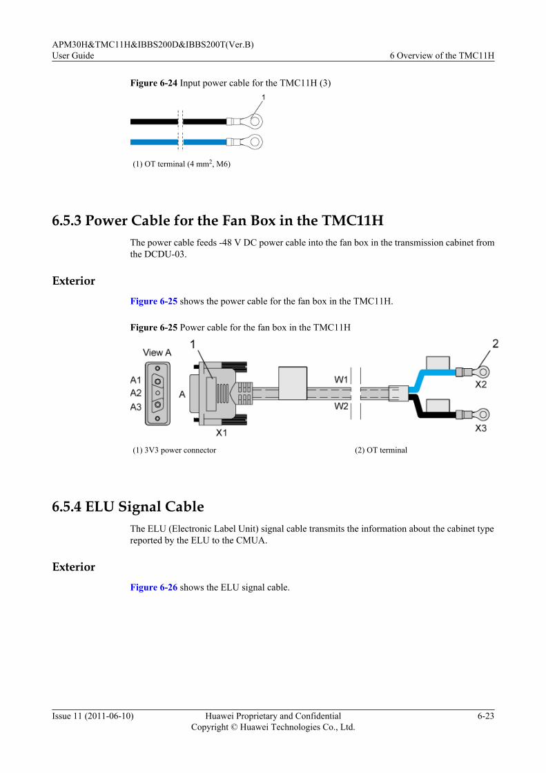
Figure 6-24 Input power cable for the TMC11H (3)
(1) OT terminal (4 mm2, M6)
6.5.3 Power Cable for the Fan Box in the TMC11HThe power cable feeds -48 V DC power cable into the fan box in the transmission cabinet fromthe DCDU-03.
ExteriorFigure 6-25 shows the power cable for the fan box in the TMC11H.
Figure 6-25 Power cable for the fan box in the TMC11H
(1) 3V3 power connector (2) OT terminal
6.5.4 ELU Signal CableThe ELU (Electronic Label Unit) signal cable transmits the information about the cabinet typereported by the ELU to the CMUA.
ExteriorFigure 6-26 shows the ELU signal cable.
APM30H&TMC11H&IBBS200D&IBBS200T(Ver.B)User Guide 6 Overview of the TMC11H
Issue 11 (2011-06-10) Huawei Proprietary and ConfidentialCopyright © Huawei Technologies Co., Ltd.
6-23
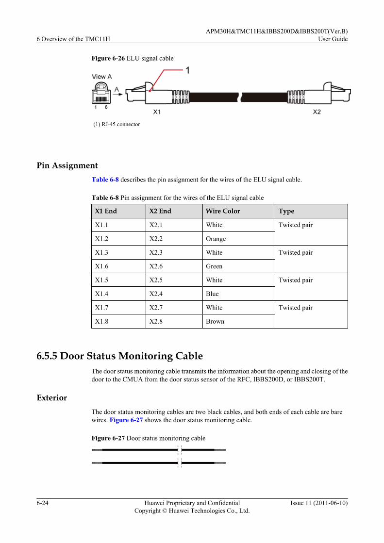
Figure 6-26 ELU signal cable
(1) RJ-45 connector
Pin AssignmentTable 6-8 describes the pin assignment for the wires of the ELU signal cable.
Table 6-8 Pin assignment for the wires of the ELU signal cable
X1 End X2 End Wire Color Type
X1.1 X2.1 White Twisted pair
X1.2 X2.2 Orange
X1.3 X2.3 White Twisted pair
X1.6 X2.6 Green
X1.5 X2.5 White Twisted pair
X1.4 X2.4 Blue
X1.7 X2.7 White Twisted pair
X1.8 X2.8 Brown
6.5.5 Door Status Monitoring CableThe door status monitoring cable transmits the information about the opening and closing of thedoor to the CMUA from the door status sensor of the RFC, IBBS200D, or IBBS200T.
ExteriorThe door status monitoring cables are two black cables, and both ends of each cable are barewires. Figure 6-27 shows the door status monitoring cable.
Figure 6-27 Door status monitoring cable
6 Overview of the TMC11HAPM30H&TMC11H&IBBS200D&IBBS200T(Ver.B)
User Guide
6-24 Huawei Proprietary and ConfidentialCopyright © Huawei Technologies Co., Ltd.
Issue 11 (2011-06-10)

6.5.6 Monitoring Signal Cable for the Fan on the Front DoorThe monitoring signal cable feeds power into the fan on the front door of the APM30H orTMC11H and transmits fan monitoring signals to the CMUA.
ExteriorFigure 6-28 shows the monitoring signal cable for the fan on the front door.
Figure 6-28 Monitoring signal cable for the fan on the front door
Pin AssignmentTable 6-9 describes the pin assignment for the wires of the monitoring signal cable for the fanon the front door.
Table 6-9 Pin assignment for the wires of the monitoring signal cable for the fan on the frontdoor
Wire X1 End X2 End Color
W1 X1.1 X2.1 Black
W2 X1.2 X2.2 Black
W3 X1.3 X2.3 Black
W4 X1.4 X2.4 Black
APM30H&TMC11H&IBBS200D&IBBS200T(Ver.B)User Guide 6 Overview of the TMC11H
Issue 11 (2011-06-10) Huawei Proprietary and ConfidentialCopyright © Huawei Technologies Co., Ltd.
6-25

7 SLPU
About This Chapter
The signal lightning protection unit (SLPU), which can be optionally configured with the UFLP,UELP, or USLP2, provides the signal surge protection.
7.1 Exterior of SLPUThe SLPU has a case structure, which requires a 19-inch wide and 1 U high space.
7.2 Configuration of the SLPUThis section describes the configuration principles of the SPLU.
7.3 UELPEach Universal E1/T1 Lightning Protection Unit (UELP) provides surge protection for fourpaths of E1/T1 signals.
7.4 UFLPThe universal FE/GE lightning protection (UFLP) board is a universal FE surge protection unit,each UFLP supports 2-way FE surge protection.
7.5 USLP2The Universal Signal Lightning Protection Unit Type 2 (USLP2) is a dry contact surge protectionunit. It is optional and can be installed in the SLPU.
APM30H&TMC11H&IBBS200D&IBBS200T(Ver.B)User Guide 7 SLPU
Issue 11 (2011-06-10) Huawei Proprietary and ConfidentialCopyright © Huawei Technologies Co., Ltd.
7-1
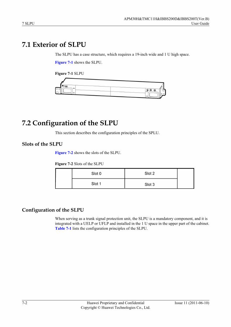
7.1 Exterior of SLPUThe SLPU has a case structure, which requires a 19-inch wide and 1 U high space.
Figure 7-1 shows the SLPU.
Figure 7-1 SLPU
7.2 Configuration of the SLPUThis section describes the configuration principles of the SPLU.
Slots of the SLPUFigure 7-2 shows the slots of the SLPU.
Figure 7-2 Slots of the SLPU
Configuration of the SLPUWhen serving as a trunk signal protection unit, the SLPU is a mandatory component, and it isintegrated with a UELP or UFLP and installed in the 1 U space in the upper part of the cabinet.Table 7-1 lists the configuration principles of the SLPU.
7 SLPUAPM30H&TMC11H&IBBS200D&IBBS200T(Ver.B)
User Guide
7-2 Huawei Proprietary and ConfidentialCopyright © Huawei Technologies Co., Ltd.
Issue 11 (2011-06-10)

Table 7-1 Configuration principles of the SLPU (1)
Board Optional/Mandatory
MaximumQuantity
Slot ConfigurationRestriction
UELP Optional 4 Slots 0 to 3 The priorities ofthe slots inconfigurationare as follows indescendingorder: slot 2, slot0, slot 1, and slot3.
UFLP Optional 1 Slot 3 If both theUELP andUFLP areconfigured, theUFLP isinstalled in a slotwith a higherpriority than theUELP.
When serving as a monitoring signal protection unit for not more than 16 dry contacts, the SLPUis an optional component, and it is integrated with two USLP2s and installed in the 1 U spaceat the bottom of the BBU. Table 7-2 lists the configuration principles of the SLPU.
Table 7-2 Configuration principles of the SLPU (2)
Board Optional/Mandatory
Quantity Slot ConfigurationRestriction
USLP2 Optional 2 Slots 2 and 3 -
7.3 UELPEach Universal E1/T1 Lightning Protection Unit (UELP) provides surge protection for fourpaths of E1/T1 signals.
Panel
Figure 7-3 shows the panel of the UELP.
Figure 7-3 UELP panel
APM30H&TMC11H&IBBS200D&IBBS200T(Ver.B)User Guide 7 SLPU
Issue 11 (2011-06-10) Huawei Proprietary and ConfidentialCopyright © Huawei Technologies Co., Ltd.
7-3
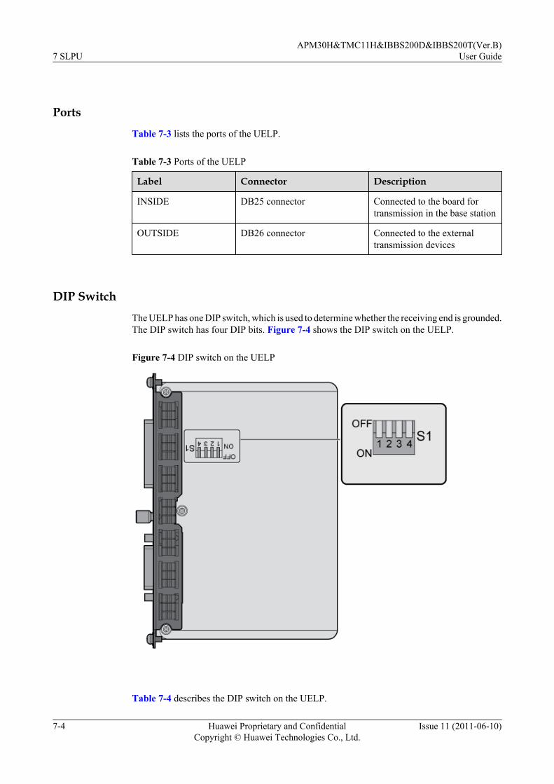
Ports
Table 7-3 lists the ports of the UELP.
Table 7-3 Ports of the UELP
Label Connector Description
INSIDE DB25 connector Connected to the board fortransmission in the base station
OUTSIDE DB26 connector Connected to the externaltransmission devices
DIP Switch
The UELP has one DIP switch, which is used to determine whether the receiving end is grounded.The DIP switch has four DIP bits. Figure 7-4 shows the DIP switch on the UELP.
Figure 7-4 DIP switch on the UELP
Table 7-4 describes the DIP switch on the UELP.
7 SLPUAPM30H&TMC11H&IBBS200D&IBBS200T(Ver.B)
User Guide
7-4 Huawei Proprietary and ConfidentialCopyright © Huawei Technologies Co., Ltd.
Issue 11 (2011-06-10)

Table 7-4 DIP switch on the UELP
DIPSwitch
Bit Status Description
1 2 3 4
S1 OFF OFF OFF OFF Not grounded
Other status Grounded
NOTEThe 75-ohm E1 cable can be either grounded or not grounded, whereas the 120-ohm E1 cable and the 100-ohm T1 cable cannot be grounded.
7.4 UFLPThe universal FE/GE lightning protection (UFLP) board is a universal FE surge protection unit,each UFLP supports 2-way FE surge protection.
Panel
Figure 7-5 shows the panel of the UFLP.
Figure 7-5 Panel of the UFLP
Ports
Table 7-5 describes the ports on the panel of the UFLP.
Table 7-5 Ports on the panel of the UFLP
Port Location Label Connector Type Description
INSIDE side FE0, FE1 RJ-45 Connected to theboard fortransmission in thebase station
OUTSIDE side FE0, FE1 RJ-45 Connected to theexternaltransmissiondevices
APM30H&TMC11H&IBBS200D&IBBS200T(Ver.B)User Guide 7 SLPU
Issue 11 (2011-06-10) Huawei Proprietary and ConfidentialCopyright © Huawei Technologies Co., Ltd.
7-5
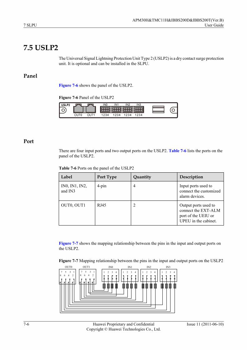
7.5 USLP2The Universal Signal Lightning Protection Unit Type 2 (USLP2) is a dry contact surge protectionunit. It is optional and can be installed in the SLPU.
PanelFigure 7-6 shows the panel of the USLP2.
Figure 7-6 Panel of the USLP2
PortThere are four input ports and two output ports on the USLP2. Table 7-6 lists the ports on thepanel of the USLP2.
Table 7-6 Ports on the panel of the USLP2
Label Port Type Quantity Description
IN0, IN1, IN2,and IN3
4-pin 4 Input ports used toconnect the customizedalarm devices.
OUT0, OUT1 RJ45 2 Output ports used toconnect the EXT-ALMport of the UEIU orUPEU in the cabinet.
Figure 7-7 shows the mapping relationship between the pins in the input and output ports onthe USLP2.
Figure 7-7 Mapping relationship between the pins in the input and output ports on the USLP2
1 2 3 4 1 2 3 4 1 2 3 4 1 2 3 48 6 4 27 5 3 1
8 6 4 27 5 3 1
IN0 IN1 IN2 IN3OUT0 OUT1
7 SLPUAPM30H&TMC11H&IBBS200D&IBBS200T(Ver.B)
User Guide
7-6 Huawei Proprietary and ConfidentialCopyright © Huawei Technologies Co., Ltd.
Issue 11 (2011-06-10)

Table 7-7 lists the mapping relationship between the pins in the input and output ports on theUSLP2.
Table 7-7 Mapping relationship between the pins in the input and output ports on the USLP2
Input Output
Label Pin Label Pin
IN0 IN0.1 OUT1 OUT1.1
IN0.2 OUT1.2
IN0.3 OUT1.4
IN0.4 OUT1.5
IN1 IN1.1 OUT1.3
IN1.2 OUT1.6
IN1.3 OUT1.7
IN1.4 OUT1.8
IN2 IN2.1 OUT0 OUT0.1
IN2.2 OUT0.2
IN2.3 OUT0.4
IN2.4 OUT0.5
IN3 IN3.1 OUT0.3
IN3.2 OUT0.6
IN3.3 OUT0.7
IN3.4 OUT0.8
For details about the application of the USLP2, see 7.2 Configuration of the SLPU.
APM30H&TMC11H&IBBS200D&IBBS200T(Ver.B)User Guide 7 SLPU
Issue 11 (2011-06-10) Huawei Proprietary and ConfidentialCopyright © Huawei Technologies Co., Ltd.
7-7


8 Maintaining the Hardware for theAPM30H&TMC11H&IBBS200D&IBBS200T
About This Chapter
If the APM30H&TMC11H&IBBS200D&IBBS200T must be powered off for maintenance, theduration of the power-off state cannot exceed 48 hours.
8.1 Routine MaintenanceThe APM30H needs regular inspection so that faults, if any, can be cleared in time.
8.2 Replacing the PMUReplace the PMU if it is faulty and cannot be repaired.
8.3 Replacing the PSUIf the Power Supply Unit (PSU) is faulty and cannot be repaired in time, you must replace it.
8.4 Replacing the EPS SubrackReplace the EPS subrack if it is faulty and cannot be repaired.
8.5 Replacing the AC Surge ProtectorIf the AC surge protector is faulty, you must replace it.
8.6 Replacing the FuseWhen certain power equipment, which has high current requirements, is connected to a DCoutput port on the EPS subrack, the fuse on the port need to be replaced if it cannot meet thehigh-current requirement. Replacing the fuse that controls the port for supplying power to theBBU disrupts all the services carried by the base station.
8.7 Replacing the Fan Box in the APM30HReplace the fan box in the APM30H if it is faulty.
8.8 Replacing the Fan on the Front Door of the APM30HThere are two types of heat exchanger installed on the front door of the APM30H: modularizedheat exchanger and non-modularized heat exchanger. The procedure for replacing the fan on thefront door of the APM30H varies according to the type of heat exchanger.
8.9 Replacing the HeaterReplace the heater in the APM30H or TMC11H if it is faulty and cannot be repaired.
APM30H&TMC11H&IBBS200D&IBBS200T(Ver.B)User Guide
8 Maintaining the Hardware for theAPM30H&TMC11H&IBBS200D&IBBS200T
Issue 11 (2011-06-10) Huawei Proprietary and ConfidentialCopyright © Huawei Technologies Co., Ltd.
8-1
8.10 Replacing the Fan Box in the TMC11HReplace the TMC11H if it is faulty and cannot be repaired.
8.11 Replacing the BatteriesIf batteries are faulty or deteriorate, you must replace them. Generally, batteries are replaced inbatches.
8.12 Replacing the TEC Cooler of the IBBS200TThe TEC cooler helps dissipate the heat of batteries to ensure the normal operation of theIBBS200T in high-temperature areas. If the TEC cooler is faulty and cannot be repaired in time,you must replace it.
8.13 Replacing the Fan on the Front Door of the IBBS200DReplace the centrifugal fan on the front door of the IBBS200D if it is faulty and cannot berepaired.
8.14 Replacing the CMUAIf the Central Monitoring Unit type A (CMUA) on the front panel of the IBBS200D or IBBS200Tcabinet is faulty, you must replace it.
8.15 Replacing the ELUThe ELU reports the information about the cabinet type. If the ELU is faulty, you must replaceit.
8 Maintaining the Hardware for theAPM30H&TMC11H&IBBS200D&IBBS200T
APM30H&TMC11H&IBBS200D&IBBS200T(Ver.B)User Guide
8-2 Huawei Proprietary and ConfidentialCopyright © Huawei Technologies Co., Ltd.
Issue 11 (2011-06-10)

8.1 Routine MaintenanceThe APM30H needs regular inspection so that faults, if any, can be cleared in time.
Table 8-1 Routine maintenance items
Item CheckingFrequency
Method
Operation
Checking whetherthe output voltage isnormal
Onceeverysixmonths
Multimeter
For details, see Checking the Power-On Status ofthe APM30H.
Checking whetherthe fans areoperational
Onceeverysixmonths
Visualinspection
l For details about how to handle the faulty fanon the top of the APM30H, see 8.7 Replacingthe Fan Box in the APM30H .
l For details about how to handle the faulty fanon the front door of the APM30H, see 8.8.3Replacing the Fan for the Non-Modularized Heat Exchanger Installed onthe Front Door.
l For details about how to handle the faulty fanin the IBBS200D, see 8.13 Replacing the Fanon the Front Door of the IBBS200D.
Checking whetherthe LEDs areoperational
Onceeverysixmonths
Visualinspection
l For details on the LEDs on the PMU, seeTable 3-8.
l For details on the LEDs on the CMUA, seeTable 6-4.
l When the alarm LED is ON, query alarms onthe BAM, and then clear them.
The paint andgalvanizationcoating on thesurface of thecabinet are notpeeling off or havescratches.
Onceeverysixmonths
Visualinspection
-
8.2 Replacing the PMUReplace the PMU if it is faulty and cannot be repaired.
APM30H&TMC11H&IBBS200D&IBBS200T(Ver.B)User Guide
8 Maintaining the Hardware for theAPM30H&TMC11H&IBBS200D&IBBS200T
Issue 11 (2011-06-10) Huawei Proprietary and ConfidentialCopyright © Huawei Technologies Co., Ltd.
8-3

Prerequisitel The tools and materials, such as an ESD wrist strap or a pair of ESD gloves, Phillips
screwdriver, ESD box or bag, and key to the cabinet door are ready.l The quantity and model of the faulty modules are confirmed, and new modules of the same
quantity and model are ready.l The authorized personnel are permitted to enter the site. The required keys are available.
Contextl Figure 8-1 shows the installation position of the PMU in the EPS subrack.
Figure 8-1 Installation position of the PMU
l The PMU is hot-swappable.
Procedure
Step 1 Wear an ESD wrist strap or a pair of ESD gloves.
CAUTIONTake proper ESD protection measures, for example, wear an ESD wrist strap or a pair of ESDgloves, to prevent electrostatic damage to the boards, modules, or electronic components.
Step 2 Record all the cable connections on the panel of the faulty PMU.
Step 3 Disconnect all cables from the panel of the PMU.
CAUTIONWhen linking the DB50 connector of the environment monitoring signal cable, you should pressthe latches on both sides of the connector with your hands and plug or unplug the connectorperpendicularly to or from the panel on the HPMI to prevent false monitoring alarms caused bybent pins.
8 Maintaining the Hardware for theAPM30H&TMC11H&IBBS200D&IBBS200T
APM30H&TMC11H&IBBS200D&IBBS200T(Ver.B)User Guide
8-4 Huawei Proprietary and ConfidentialCopyright © Huawei Technologies Co., Ltd.
Issue 11 (2011-06-10)

Step 4 Use a Phillips screwdriver to remove the two screws from the ejector lever of the panel of thePMU.
Step 5 Pull the ejector lever gently to disconnect the buckle of the PMU from the subrack, and thenremove the PMU from the slot, as shown in Figure 8-2.
Figure 8-2 Removing the PMU
Step 6 Place the faulty PMU into an ESD box or bag.
Step 7 Take out a new PMU, and set the pins on the DIP switch on the PMU to the same positions asthose on the faulty PMU, as shown in Figure 8-3.
Figure 8-3 The position of the DIP switch
Step 8 Place the new PMU in the corresponding slot, loosen the screws on the ejector lever of the PMU,and then pull out the ejector lever.
Step 9 Slide the module along the guide rails into the slot until it is in position, and then push the ejectorlever back.
Step 10 Tighten the two screws on the ejector lever. Figure 8-4 shows the installation procedure.
APM30H&TMC11H&IBBS200D&IBBS200T(Ver.B)User Guide
8 Maintaining the Hardware for theAPM30H&TMC11H&IBBS200D&IBBS200T
Issue 11 (2011-06-10) Huawei Proprietary and ConfidentialCopyright © Huawei Technologies Co., Ltd.
8-5

Figure 8-4 Installing the PMU
Step 11 Connect the cables to the ports on the panel of the new PMU based on the cable connectionrecords.
Step 12 Check the status of the LEDs to determine whether the new PMU works properly. For detailson the status of the LEDs, see PMU.
Step 13 Take off the ESD wrist strap or gloves, and pack up all the tools.
----End
Follow-up Procedurel Place the replaced module into the ESD box or bag. Then, place the ESD box or bag into
a carton padded with foam or into the packing box of the new module.
l Fill in the fault form with the details of the replaced module.
l Contact the local Huawei office to handle the faulty module.
8.3 Replacing the PSUIf the Power Supply Unit (PSU) is faulty and cannot be repaired in time, you must replace it.
Prerequisitel The tools and materials, such as an ESD wrist strap or a pair of ESD gloves, Phillips
screwdriver, ESD box or bag, and key to the cabinet door are ready.
l The quantity and model of the faulty modules are confirmed, and new modules of the samequantity and model are ready.
l The authorized personnel are permitted to enter the site. The required keys are available.
8 Maintaining the Hardware for theAPM30H&TMC11H&IBBS200D&IBBS200T
APM30H&TMC11H&IBBS200D&IBBS200T(Ver.B)User Guide
8-6 Huawei Proprietary and ConfidentialCopyright © Huawei Technologies Co., Ltd.
Issue 11 (2011-06-10)
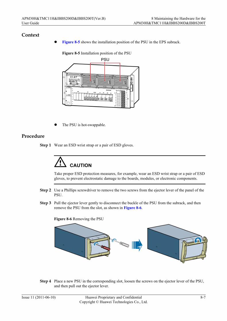
Contextl Figure 8-5 shows the installation position of the PSU in the EPS subrack.
Figure 8-5 Installation position of the PSU
l The PSU is hot-swappable.
Procedure
Step 1 Wear an ESD wrist strap or a pair of ESD gloves.
CAUTIONTake proper ESD protection measures, for example, wear an ESD wrist strap or a pair of ESDgloves, to prevent electrostatic damage to the boards, modules, or electronic components.
Step 2 Use a Phillips screwdriver to remove the two screws from the ejector lever of the panel of thePSU.
Step 3 Pull the ejector lever gently to disconnect the buckle of the PSU from the subrack, and thenremove the PSU from the slot, as shown in Figure 8-6.
Figure 8-6 Removing the PSU
Step 4 Place a new PSU in the corresponding slot, loosen the screws on the ejector lever of the PSU,and then pull out the ejector lever.
APM30H&TMC11H&IBBS200D&IBBS200T(Ver.B)User Guide
8 Maintaining the Hardware for theAPM30H&TMC11H&IBBS200D&IBBS200T
Issue 11 (2011-06-10) Huawei Proprietary and ConfidentialCopyright © Huawei Technologies Co., Ltd.
8-7
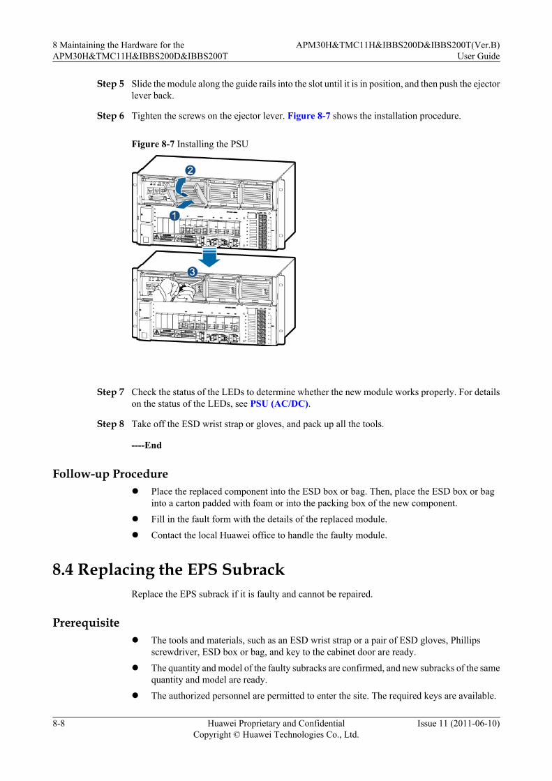
Step 5 Slide the module along the guide rails into the slot until it is in position, and then push the ejectorlever back.
Step 6 Tighten the screws on the ejector lever. Figure 8-7 shows the installation procedure.
Figure 8-7 Installing the PSU
Step 7 Check the status of the LEDs to determine whether the new module works properly. For detailson the status of the LEDs, see PSU (AC/DC).
Step 8 Take off the ESD wrist strap or gloves, and pack up all the tools.
----End
Follow-up Procedurel Place the replaced component into the ESD box or bag. Then, place the ESD box or bag
into a carton padded with foam or into the packing box of the new component.
l Fill in the fault form with the details of the replaced module.
l Contact the local Huawei office to handle the faulty module.
8.4 Replacing the EPS SubrackReplace the EPS subrack if it is faulty and cannot be repaired.
Prerequisitel The tools and materials, such as an ESD wrist strap or a pair of ESD gloves, Phillips
screwdriver, ESD box or bag, and key to the cabinet door are ready.
l The quantity and model of the faulty subracks are confirmed, and new subracks of the samequantity and model are ready.
l The authorized personnel are permitted to enter the site. The required keys are available.
8 Maintaining the Hardware for theAPM30H&TMC11H&IBBS200D&IBBS200T
APM30H&TMC11H&IBBS200D&IBBS200T(Ver.B)User Guide
8-8 Huawei Proprietary and ConfidentialCopyright © Huawei Technologies Co., Ltd.
Issue 11 (2011-06-10)
Contextl Replacing the EPS subrack disrupts all the services carried by the base station.
l It takes about 30 minutes to replace the EPS subrack.
Procedure
Step 1 Wear an ESD wrist strap or a pair of ESD gloves.
CAUTIONTake proper ESD protection measures, for example, wear an ESD wrist strap or a pair of ESDgloves, to prevent electrostatic damage to the boards, modules, or electronic components.
Step 2 Set the circuit breaker labeled BAT on the panel of the EPS subrack to OFF.
Step 3 Set the three PSU circuit breakers on the panel of the EPS subrack to OFF.
Step 4 Turn off the AC input of the APM30H.
Step 5 Disconnect the ground cable of the EPS subrack from the ground bar on the left side of thecabinet.
Step 6 Remove the PMU and PSU from the EPS subrack. For details, see 8.2 Replacing the PMU and8.3 Replacing the PSU respectively.
Step 7 Use a Phillips screwdriver to remove the cable support from the right side of the EPS subrack.
Step 8 Label the cables that are delivered with the EPS subrack and connected to the right side of theEPS subrack, and then disconnect the cables.
Step 9 Loosen the screws on the AC protecting hood on the left side of the EPS subrack, and thenremove the protecting hood.
Step 10 Label the AC input power cable and AC output power cable on the left side of the EPS subrack,and then disconnect the cables.
CAUTIONThe PE wire of the AC input power cable is connected to a hexagonal screw on a mounting earof the EPS subrack. The hexagonal screw must be reserved properly after the PE wire isdisconnected.
Step 11 Label the DC output cable on the right side of the EPS subrack, and then disconnect the cable.
Step 12 Remove the remaining seven retention screws from both sides of the EPS subrack, and thenslowly pull the subrack out of the cabinet, as shown in Figure 8-8.
APM30H&TMC11H&IBBS200D&IBBS200T(Ver.B)User Guide
8 Maintaining the Hardware for theAPM30H&TMC11H&IBBS200D&IBBS200T
Issue 11 (2011-06-10) Huawei Proprietary and ConfidentialCopyright © Huawei Technologies Co., Ltd.
8-9
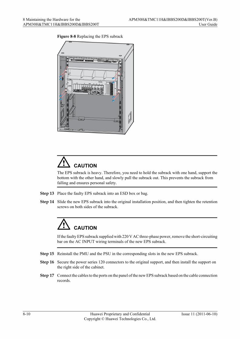
Figure 8-8 Replacing the EPS subrack
CAUTIONThe EPS subrack is heavy. Therefore, you need to hold the subrack with one hand, support thebottom with the other hand, and slowly pull the subrack out. This prevents the subrack fromfalling and ensures personal safety.
Step 13 Place the faulty EPS subrack into an ESD box or bag.
Step 14 Slide the new EPS subrack into the original installation position, and then tighten the retentionscrews on both sides of the subrack.
CAUTIONIf the faulty EPS subrack supplied with 220 V AC three-phase power, remove the short-circuitingbar on the AC INPUT wiring terminals of the new EPS subrack.
Step 15 Reinstall the PMU and the PSU in the corresponding slots in the new EPS subrack.
Step 16 Secure the power series 120 connectors to the original support, and then install the support onthe right side of the cabinet.
Step 17 Connect the cables to the ports on the panel of the new EPS subrack based on the cable connectionrecords.
8 Maintaining the Hardware for theAPM30H&TMC11H&IBBS200D&IBBS200T
APM30H&TMC11H&IBBS200D&IBBS200T(Ver.B)User Guide
8-10 Huawei Proprietary and ConfidentialCopyright © Huawei Technologies Co., Ltd.
Issue 11 (2011-06-10)
CAUTIONThe PE wire of the AC input power cable must be connected to the hexagonal screw that isremoved in Step 10. Otherwise, the level of reliability is low.
Step 18 Secure the AC protecting hood to the left side of the EPS subrack, and then tighten the screws.
Step 19 Turn on the AC input of the APM30H.
Step 20 Set the three PSU circuit breakers on the panel of the EPS subrack to ON.
Step 21 Set the circuit breaker labeled BAT on the EPS subrack to ON.
Step 22 Check the status of the LEDs on the PMU and PSU to determine whether the new EPS subrackworks properly. For details on the status of the LEDs, see PMU and PSU (AC/DC).
Step 23 Take off the ESD wrist strap or gloves, and pack up all the tools.
----End
Follow-up Procedurel Place the replaced component into the ESD box or bag. Then, place the ESD box or bag
into a carton padded with foam or into the packing box of the new component.l Fill in the fault form with the details of the replaced component.l Contact the local Huawei office to handle the faulty component.
8.5 Replacing the AC Surge ProtectorIf the AC surge protector is faulty, you must replace it.
Prerequisitel The tools and materials, such as an ESD wrist strap or a pair of ESD gloves, ESD box or
bag, and key to the cabinet door are ready.l The quantity and model of the faulty modules are confirmed, and new modules of the same
quantity and model are ready.l The authorized personnel are permitted to enter the site. The required keys are available.
Contextl Figure 8-9 shows the installation position of the AC surge protector in the EPS subrack.
APM30H&TMC11H&IBBS200D&IBBS200T(Ver.B)User Guide
8 Maintaining the Hardware for theAPM30H&TMC11H&IBBS200D&IBBS200T
Issue 11 (2011-06-10) Huawei Proprietary and ConfidentialCopyright © Huawei Technologies Co., Ltd.
8-11

Figure 8-9 Installation position of the AC surge protector
(1) AC surge protector
l When the color of the protecting hood on the front panel of the surge protector changesfrom green to red, the protector is faulty and you must replace it.
Procedure
Step 1 Wear an ESD wrist strap or a pair of ESD gloves.
CAUTIONTake proper ESD protection measures, for example, wear an ESD wrist strap or a pair of ESDgloves, to prevent electrostatic damage to the boards, modules, or electronic components.
Step 2 Press the upper and lower ends of the surge protector, and then remove the protector, as shownin Figure 8-10.
Figure 8-10 Removing the surge protector
Step 3 Place the faulty AC surge protector into an ESD box or bag.
8 Maintaining the Hardware for theAPM30H&TMC11H&IBBS200D&IBBS200T
APM30H&TMC11H&IBBS200D&IBBS200T(Ver.B)User Guide
8-12 Huawei Proprietary and ConfidentialCopyright © Huawei Technologies Co., Ltd.
Issue 11 (2011-06-10)

Step 4 Place the new surge protector in the corresponding slot, and then push it until it is securelyinstalled.
Step 5 Check the color of the protecting hood on the front panel of the surge protector to determinewhether the new surge protector works properly. When the surge protector works properly, thecolor is green.
Step 6 Take off the ESD wrist strap or gloves, and pack up all the tools.
----End
Follow-up Procedurel Place the replaced module into the ESD box or bag. Then, place the ESD box or bag into
a carton padded with foam or into the packing box of the new module.l Fill in the fault form with the details of the replaced module.l Contact the local Huawei office to handle the faulty module.
8.6 Replacing the FuseWhen certain power equipment, which has high current requirements, is connected to a DCoutput port on the EPS subrack, the fuse on the port need to be replaced if it cannot meet thehigh-current requirement. Replacing the fuse that controls the port for supplying power to theBBU disrupts all the services carried by the base station.
Prerequisitel The tools and materials, such as an ESD wrist strap or a pair of ESD gloves, new fuse, ESD
box or bag, and key to the cabinet door, are ready.l The quantity and model of the faulty fuses are confirmed, and new fuses of the same quantity
and model are ready.l The authorized personnel are permitted to enter the site. The required keys are available.
Contextl Figure 8-11 shows the installation position of the fuse and spare fuse box in the EPS
subrack.
Figure 8-11 Installation position of the fuse and spare fuse box
(1) Extraction tool (2) Spare fuse box (3) Fuse
APM30H&TMC11H&IBBS200D&IBBS200T(Ver.B)User Guide
8 Maintaining the Hardware for theAPM30H&TMC11H&IBBS200D&IBBS200T
Issue 11 (2011-06-10) Huawei Proprietary and ConfidentialCopyright © Huawei Technologies Co., Ltd.
8-13

l The fuse is hot-swappable.
CAUTIONThe specifications of the fuse vary according to the ambient temperature. For details on thederating of the fuse, see the general specifications of the fuse. If the fuse works at a normaltemperature of 25°C, the operating current cannot be greater than 75% of its rated current.
Procedure
Step 1 Wear an ESD wrist strap or a pair of ESD gloves.
CAUTIONTake proper ESD protection measures, for example, wear an ESD wrist strap or a pair of ESDgloves, to prevent electrostatic damage to the boards, modules, or electronic components.
Step 2 Take the extraction tool out of the mounting ear on the right side of the EPS subrack.
Figure 8-12 shows the exterior and position of the extraction tool.
Figure 8-12 Position of the extraction tool in the cabinet
Step 3 Use the extraction tool to remove the faulty fuse, as shown in Figure 8-13.
8 Maintaining the Hardware for theAPM30H&TMC11H&IBBS200D&IBBS200T
APM30H&TMC11H&IBBS200D&IBBS200T(Ver.B)User Guide
8-14 Huawei Proprietary and ConfidentialCopyright © Huawei Technologies Co., Ltd.
Issue 11 (2011-06-10)

Figure 8-13 Removing the faulty fuse
Step 4 Place the faulty fuse into an ESD box or bag.
Step 5 Take the fuse from the spare fuse box, as shown in Figure 8-14.
Figure 8-14 Taking the spare fuse
Step 6 Insert the new fuse into the corresponding port.
Step 7 Set the circuit breaker for the new fuse to ON and check the running status of the related modulesto determine whether the fuse works properly.
Step 8 Take off the ESD wrist strap or gloves, and then pack up all the tools.
----End
Follow-up Procedurel Place the replaced component into the ESD box or bag. Then, place the ESD box or bag
into a carton padded with foam or into the packing box of the new component.
APM30H&TMC11H&IBBS200D&IBBS200T(Ver.B)User Guide
8 Maintaining the Hardware for theAPM30H&TMC11H&IBBS200D&IBBS200T
Issue 11 (2011-06-10) Huawei Proprietary and ConfidentialCopyright © Huawei Technologies Co., Ltd.
8-15
l Fill in the fault form with the details of the replaced component.
8.7 Replacing the Fan Box in the APM30HReplace the fan box in the APM30H if it is faulty.
Prerequisitel The tools and materials, such as an ESD wrist strap or a pair of ESD gloves, Phillips
screwdriver, ESD box or bag, and key to the cabinet door are ready.l The quantity and model of the faulty fan boxes are confirmed, and new fan boxes of the
same quantity and model are ready.l The authorized personnel are permitted to enter the site. The required keys are available.
Contextl The fan box in the APM30H houses the HPMI, CMUA, and fan. If any of the components
is faulty, the fan box must be replaced.l It takes about 20 minutes to replace the fan box.
Procedure
Step 1 Wear an ESD wrist strap or a pair of ESD gloves.
CAUTIONTake proper ESD protection measures, for example, wear an ESD wrist strap or a pair of ESDgloves, to prevent electrostatic damage to the boards, modules, or electronic components.
Step 2 Remove the fuse corresponding to the port labeled LOAD0. For details, see 8.6 Replacing theFuse.
Step 3 Record all the cable connections on the panel of the faulty fan box.
Step 4 Disconnect all cables from the panel of the faulty fan box.
NOTE
Remove the RJ-45 connectors linked to the COM_IN, COM_OUT, and ELU ports from the panel of the CMUAthrough the holes at the baffle plate on the ports, as shown in Figure 8-15.
8 Maintaining the Hardware for theAPM30H&TMC11H&IBBS200D&IBBS200T
APM30H&TMC11H&IBBS200D&IBBS200T(Ver.B)User Guide
8-16 Huawei Proprietary and ConfidentialCopyright © Huawei Technologies Co., Ltd.
Issue 11 (2011-06-10)

Figure 8-15 Top view of the fan box in the APM30H
Step 5 Remove the retention screws from the mounting ears of the fan box, and then remove the boxfrom the cabinet slowly, as shown in Figure 8-16.
Figure 8-16 Removing the fan box from the APM30H
DANGERWhen removing the fan box, do not touch the air inlet at the bottom of the fan box.
Step 6 Place the faulty fan box into an ESD box or bag.
Step 7 Slide the new fan box into the installation position, and then tighten the retention screws on themounting ears of the fan box.
Step 8 Connect the cables to the ports on the front panel of the fan box based on the cable connectionrecords, and then check that the cables are properly and correctly connected.
APM30H&TMC11H&IBBS200D&IBBS200T(Ver.B)User Guide
8 Maintaining the Hardware for theAPM30H&TMC11H&IBBS200D&IBBS200T
Issue 11 (2011-06-10) Huawei Proprietary and ConfidentialCopyright © Huawei Technologies Co., Ltd.
8-17

NOTE
You must plug or unplug the DB50 connector of the environment monitoring signal cable perpendicularlyto or from the panel on the HPMI with your hands to prevent false monitoring alarms caused by bent pins.
Step 9 Connect the fuse to the original port, and then power on the fan box.
Step 10 Check the status of the LEDs to determine whether the new fan box works properly. For detailson the status of the LEDs, see CMUA.
Step 11 Take off the ESD wrist strap or gloves, and then pack up all the tools.
----End
Follow-up Procedurel Place the replaced component into the ESD box or bag. Then, place the ESD box or bag
into a carton padded with foam or into the packing box of the new component.l Fill in the fault form with the details of the replaced component.l Contact the local Huawei office to handle the faulty component.
8.8 Replacing the Fan on the Front Door of the APM30HThere are two types of heat exchanger installed on the front door of the APM30H: modularizedheat exchanger and non-modularized heat exchanger. The procedure for replacing the fan on thefront door of the APM30H varies according to the type of heat exchanger.
8.8.1 Querying the Type of FanDetermine the type of fan to be replaced by querying the ELU information remotely as shownbelow.
8.8.2 Replacing the Fan for the Modularized Heat Exchanger Installed on the Front DoorIf the fan for the modularized heat exchanger installed in the APM30H is faulty and cannot berepaired in time, you must replace it.
8.8.3 Replacing the Fan for the Non-Modularized Heat Exchanger Installed on the Front DoorIf the fan for the non-modularized heat exchanger installed in the APM30H is faulty and cannotbe repaired in time, you must replace it.
8.8.1 Querying the Type of FanDetermine the type of fan to be replaced by querying the ELU information remotely as shownbelow.
1. Run the DSP BTSELABEL command on the LMT to query the information of the cabinetthat is configured on the GSM side or run the DSP ELABEL command on the LMT toquery the information of the cabinet that is configured on the UMTS side or the LTE side.
2. Obtain the information in the ExInfo area in the execution result to determine the type ofthe fan to be replaced.l If Heat Dissipation Parts.Panasonic is displayed in the ExInfo area, you can infer that
the type of fan to be replaced is the modularized heat exchanger.l If Heat Dissipation Parts.Panasonic is not displayed in the ExInfo area, you can infer
that the type of fan to be replaced is the non-modularized heat exchanger.
8 Maintaining the Hardware for theAPM30H&TMC11H&IBBS200D&IBBS200T
APM30H&TMC11H&IBBS200D&IBBS200T(Ver.B)User Guide
8-18 Huawei Proprietary and ConfidentialCopyright © Huawei Technologies Co., Ltd.
Issue 11 (2011-06-10)

3. Prepare the type of fan based on the type of heat exchanger in the cabinet.
8.8.2 Replacing the Fan for the Modularized Heat ExchangerInstalled on the Front Door
If the fan for the modularized heat exchanger installed in the APM30H is faulty and cannot berepaired in time, you must replace it.
Prerequisitel The tools and materials, such as an ESD wrist strap or a pair of ESD gloves, Phillips
screwdriver, cable cutter, socket screwdriver, ESD box or bag, and key to the cabinet doorare ready.
l The quantity and model of the faulty fans are confirmed. For details, see 8.8.1 Queryingthe Type of Fan.
l The authorized personnel are permitted to enter the site. The required keys are available.
Contextl Figure 8-17 shows the position of the fan in the APM30H.
Figure 8-17 Position of the fan in the APM30H
l It takes about 20 minutes to replace the fan.
Procedure
Step 1 Wear an ESD wrist strap or a pair of ESD gloves.
CAUTIONTake proper ESD protection measures, for example, wear an ESD wrist strap or a pair of ESDgloves, to prevent electrostatic damage to the boards, modules, or electronic components.
APM30H&TMC11H&IBBS200D&IBBS200T(Ver.B)User Guide
8 Maintaining the Hardware for theAPM30H&TMC11H&IBBS200D&IBBS200T
Issue 11 (2011-06-10) Huawei Proprietary and ConfidentialCopyright © Huawei Technologies Co., Ltd.
8-19

Step 2 Remove the fuse from the slot corresponding to the port labeled LOAD0 on the EPS to poweroff the CMUA. For details, see 8.6 Replacing the Fuse.
Step 3 Record the connection of the faulty cable for the fan on the fan transfer board, and then removethe cable and rubber cap from the cable outlet, as shown in Figure 8-18.
Figure 8-18 Remove the faulty cable for the fan
Step 4 Use a Phillips screwdriver to remove the five screws from the air duct, use a socket screwdriverto remove the nut from under the air duct, and then remove the air duct, as shown in Figure8-19.
8 Maintaining the Hardware for theAPM30H&TMC11H&IBBS200D&IBBS200T
APM30H&TMC11H&IBBS200D&IBBS200T(Ver.B)User Guide
8-20 Huawei Proprietary and ConfidentialCopyright © Huawei Technologies Co., Ltd.
Issue 11 (2011-06-10)

Figure 8-19 Removing the air duct
Step 5 Use a Phillips screwdriver to remove the other nine screws from the heat exchanger, and thenremove the heat exchanger from the front door of the APM30H, as shown in Figure 8-20.
Figure 8-20 Removing the heat exchanger
Step 6 Use a Phillips screwdriver to remove the five screws from the cover plate of the fan cavity, andthen remove the cover plate, as shown in Figure 8-21.
APM30H&TMC11H&IBBS200D&IBBS200T(Ver.B)User Guide
8 Maintaining the Hardware for theAPM30H&TMC11H&IBBS200D&IBBS200T
Issue 11 (2011-06-10) Huawei Proprietary and ConfidentialCopyright © Huawei Technologies Co., Ltd.
8-21

Figure 8-21 Removing the cover plate of the fan cavity
Step 7 Use a Phillips screwdriver to remove the four screws fixing the fan, and then remove the faultyfan, as shown in Figure 8-22.
Figure 8-22 Removing the faulty fan
8 Maintaining the Hardware for theAPM30H&TMC11H&IBBS200D&IBBS200T
APM30H&TMC11H&IBBS200D&IBBS200T(Ver.B)User Guide
8-22 Huawei Proprietary and ConfidentialCopyright © Huawei Technologies Co., Ltd.
Issue 11 (2011-06-10)

Step 8 Install the new fan in the fan cavity, and then tighten the four screws on the fan.
Step 9 Reinstall the cover plate of the fan cavity on the heat exchanger, and then tighten the five screwson the cover plate of the fan cavity.
Step 10 Lead the cable for the new fan through the cable outlet on the right of the front door, and theninstall a rubber cap on the cable outlet.
Step 11 Reinstall the heat exchanger on the front door, and then tighten the nine screws on the panel ofthe heat exchanger.
Step 12 Reinstall the air duct on the heat exchanger, and then tighten the five screws and one nut.
Step 13 Reinstall the cable for the new fan on the fan transfer board based on the cable connectionsrecorded.
Step 14 Put the fuse back into the slot corresponding to the port labeled LOAD0.
Step 15 Check the running of the fans and status of the LEDs on the CMUA to determine whether thenew fan works properly. For details about the status of the LEDs, see CMUA.
Step 16 Take off the ESD wrist strap or gloves, and then pack up all the tools.
----End
Follow-up Procedurel Place the replaced component into the ESD box or bag. Then, place the ESD box or bag
into a carton padded with foam or into the packing box of the new component.
l Fill in the fault form with the details of the replaced component.
l Contact the local Huawei office to handle the faulty component.
8.8.3 Replacing the Fan for the Non-Modularized Heat ExchangerInstalled on the Front Door
If the fan for the non-modularized heat exchanger installed in the APM30H is faulty and cannotbe repaired in time, you must replace it.
Prerequisitel The tools and materials, such as an ESD wrist strap or a pair of ESD gloves, Phillips
screwdriver, ESD box or bag, and key to the cabinet door, are ready.
l The quantity and model of the faulty fans are confirmed. For details, see 8.8.1 Queryingthe Type of Fan.
l The authorized personnel are permitted to enter the site. The required keys are available.
Contextl Figure 8-23 shows the position of the fan in the APM30H.
APM30H&TMC11H&IBBS200D&IBBS200T(Ver.B)User Guide
8 Maintaining the Hardware for theAPM30H&TMC11H&IBBS200D&IBBS200T
Issue 11 (2011-06-10) Huawei Proprietary and ConfidentialCopyright © Huawei Technologies Co., Ltd.
8-23

Figure 8-23 Position of the fan in the APM30H
l It takes about 20 minutes to replace the fan.
Procedure
Step 1 Wear an ESD wrist strap or a pair of ESD gloves.
CAUTIONTake proper ESD protection measures, for example, wear an ESD wrist strap or a pair of ESDgloves, to prevent electrostatic damage to the boards, modules, or electronic components.
Step 2 Remove the fuse from the slot corresponding to the port labeled LOAD0. For details, see 8.6Replacing the Fuse.
Step 3 Remove the connector linked to the port labeled FAN_EXT from the panel of the CMUA topower off the fan on the front door of the APM30H.
Step 4 Loosen the screws on the cover plate of the fan transfer board, and then remove the cover plate.
Step 5 Label the cables connected to the faulty fan, and then disconnect the cables, as shown in 1 ofFigure 8-24.
Step 6 Remove the eight screws from the cover plate of the fan and remove the cover plate, as shownin 2 of Figure 8-24.
Step 7 Remove the baffle and rubber cap from the cable outlet on the side of the fan cavity. Then,remove the cable for the fan, as shown in 3 of Figure 8-24.
8 Maintaining the Hardware for theAPM30H&TMC11H&IBBS200D&IBBS200T
APM30H&TMC11H&IBBS200D&IBBS200T(Ver.B)User Guide
8-24 Huawei Proprietary and ConfidentialCopyright © Huawei Technologies Co., Ltd.
Issue 11 (2011-06-10)
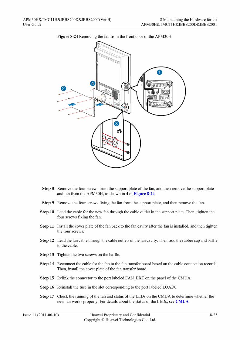
Figure 8-24 Removing the fan from the front door of the APM30H
Step 8 Remove the four screws from the support plate of the fan, and then remove the support plateand fan from the APM30H, as shown in 4 of Figure 8-24.
Step 9 Remove the four screws fixing the fan from the support plate, and then remove the fan.
Step 10 Lead the cable for the new fan through the cable outlet in the support plate. Then, tighten thefour screws fixing the fan.
Step 11 Install the cover plate of the fan back to the fan cavity after the fan is installed, and then tightenthe four screws.
Step 12 Lead the fan cable through the cable outlets of the fan cavity. Then, add the rubber cap and baffleto the cable.
Step 13 Tighten the two screws on the baffle.
Step 14 Reconnect the cable for the fan to the fan transfer board based on the cable connection records.Then, install the cover plate of the fan transfer board.
Step 15 Relink the connector to the port labeled FAN_EXT on the panel of the CMUA.
Step 16 Reinstall the fuse in the slot corresponding to the port labeled LOAD0.
Step 17 Check the running of the fan and status of the LEDs on the CMUA to determine whether thenew fan works properly. For details about the status of the LEDs, see CMUA.
APM30H&TMC11H&IBBS200D&IBBS200T(Ver.B)User Guide
8 Maintaining the Hardware for theAPM30H&TMC11H&IBBS200D&IBBS200T
Issue 11 (2011-06-10) Huawei Proprietary and ConfidentialCopyright © Huawei Technologies Co., Ltd.
8-25

Step 18 Take off the ESD wrist strap or gloves, and then pack up all the tools.
----End
Follow-up Procedurel Place the replaced component into the ESD box or bag. Then, place the ESD box or bag
into a carton padded with foam or into the packing box of the new component.l Fill in the fault form with the details of the replaced component.l Contact the local Huawei office to handle the faulty component.
8.9 Replacing the HeaterReplace the heater in the APM30H or TMC11H if it is faulty and cannot be repaired.
Prerequisitel The tools and materials, such as an ESD wrist strap or a pair of ESD gloves, diagonal pliers,
flat-head screwdriver, Phillips screwdriver, insulation screwdriver, ESD box or bag, andkey to the cabinet door are ready.
l The quantity and model of the faulty heaters are confirmed, and new heaters of the samequantity and model and several cable ties are ready.
l The authorized personnel are permitted to enter the site. The required keys are available.
ContextThe heater can be installed in the 1 U transmission space based on the actual condition.
WARNINGAfter the installation, do not change the position of the heater during the routine operation.
Procedure
Step 1 Wear an ESD wrist strap or a pair of ESD gloves.
CAUTIONTake proper ESD protection measures, for example, wear an ESD wrist strap or a pair of ESDgloves, to prevent electrostatic damage to the boards, modules, or electronic components.
Step 2 Set the AC output circuit breaker labeled AC OUTPUT on the panel of the EPS subrack to OFF.
Step 3 Remove the connector at one end of the power cable from the heater.
Step 4 Remove the four screws from the panel of the heater. Hold the heater with one hand, and pullthe heater out of the cabinet with the other hand slightly, as shown in Figure 8-25.
8 Maintaining the Hardware for theAPM30H&TMC11H&IBBS200D&IBBS200T
APM30H&TMC11H&IBBS200D&IBBS200T(Ver.B)User Guide
8-26 Huawei Proprietary and ConfidentialCopyright © Huawei Technologies Co., Ltd.
Issue 11 (2011-06-10)

Figure 8-25 Removing the faulty heater
Step 5 Place the new heater in its installation position. Hold the new heater with one hand, and push itinto the cabinet with the other hand until the mounting ears are in contact with the columns.
Step 6 Tighten the two screws on both sides of the heater.
Step 7 Re-link the connector at one end of the power cable to the input port of the heater, as shown inFigure 8-26.
Figure 8-26 Installing the new heater
Step 8 Set the AC output circuit breaker labeled AC OUTPUT on the panel of the EPS subrack to ON.
Step 9 Take off the ESD wrist strap or gloves, and pack up all the tools.
----End
Follow-up Procedurel Place the replaced heater into the ESD box or bag. Then, place the ESD box or bag into a
carton padded with foam or into the packing box of the new heater.
l Fill in the fault form with the details of the replaced heater.
l Contact the local Huawei office to handle the faulty heater.
APM30H&TMC11H&IBBS200D&IBBS200T(Ver.B)User Guide
8 Maintaining the Hardware for theAPM30H&TMC11H&IBBS200D&IBBS200T
Issue 11 (2011-06-10) Huawei Proprietary and ConfidentialCopyright © Huawei Technologies Co., Ltd.
8-27

8.10 Replacing the Fan Box in the TMC11HReplace the TMC11H if it is faulty and cannot be repaired.
Prerequisitel The tools and materials, such as an ESD wrist strap or a pair of ESD gloves, Phillips
screwdriver, ESD box or bag, and key to the cabinet door are ready.l The quantity and model of the faulty fan boxes are confirmed, and new fan boxes of the
same quantity and model are ready.l The authorized personnel are permitted to enter the site. The required keys are available.
Contextl The fan box in the TMC11H houses the HPMI, CMUA, and fan. If any of the components
is faulty, the fan box must be replaced.l It takes about 20 minutes to replace the fan box.
ProcedureStep 1 Wear an ESD wrist strap or a pair of ESD gloves.
CAUTIONTake proper ESD protection measures, for example, wear an ESD wrist strap or a pair of ESDgloves, to prevent electrostatic damage to the boards, modules, or electronic components.
Step 2 Set the circuit breaker labeled FAN on the DCDU-03 to OFF to power off the fan box.
Step 3 Record all the cable connections on the panel of the faulty fan box.
Step 4 Disconnect all cables from the panel of the faulty fan box.NOTE
Remove the RJ-45 connectors linked to the COM_IN, COM_OUT, and ELU ports from the panel of theCMUA through the holes in the baffle plate on the ports, as shown in Figure 8-27.
Figure 8-27 Top view of the fan box in the TMC11H
8 Maintaining the Hardware for theAPM30H&TMC11H&IBBS200D&IBBS200T
APM30H&TMC11H&IBBS200D&IBBS200T(Ver.B)User Guide
8-28 Huawei Proprietary and ConfidentialCopyright © Huawei Technologies Co., Ltd.
Issue 11 (2011-06-10)

Step 5 Remove the retention screws from the mounting ears of the fan box, and then remove the boxfrom the cabinet slowly, as shown in Figure 8-28.
Figure 8-28 Removing the fan box from the TMC11H
DANGERWhen removing the fan box, do not touch the air inlet at the bottom of the fan box.
Step 6 Slide the new fan box into the installation position, and then tighten the retention screws on themounting ears of the fan box.
Step 7 Connect the cables to the ports on the front panel of the fan box based on the cable connectionrecords, and then check that the cables are properly and correctly connected.
Step 8 Set the circuit breaker labeled FAN on the DCDU-03 to ON to power on the fan box.
Step 9 Check the status of the LEDs to determine whether the new fan box works properly. For detailson the status of the LEDs, see CMUA.
Step 10 Take off the ESD wrist strap or gloves, and pack up all the tools.
----End
Follow-up Procedurel Place the replaced component into the ESD box or bag. Then, place the ESD box or bag
into a carton padded with foam or into the packing box of the new component.
l Fill in the fault form with the details of the replaced component.
l Contact the local Huawei office to handle the faulty component.
APM30H&TMC11H&IBBS200D&IBBS200T(Ver.B)User Guide
8 Maintaining the Hardware for theAPM30H&TMC11H&IBBS200D&IBBS200T
Issue 11 (2011-06-10) Huawei Proprietary and ConfidentialCopyright © Huawei Technologies Co., Ltd.
8-29

8.11 Replacing the BatteriesIf batteries are faulty or deteriorate, you must replace them. Generally, batteries are replaced inbatches.
Prerequisitel The tools and materials, such as an ESD wrist strap or a pair of ESD gloves, Phillips
screwdriver, ESD box or bag, and key to the cabinet door are ready.l The quantity and model of the faulty batteries are confirmed, and new batteries of the same
quantity and model are ready.l The authorized personnel are permitted to enter the site. The required keys are available.
ContextNOTE
After replacing 50 Ah storage batteries with 92 Ah storage batteries, you must change the value of theBC parameter. Otherwise, the performance of the storage batteries is affected.
DANGERDuring the replacement, short circuits or reverse connections cannot exist between the positiveand negative poles of the batteries. All the tools such as wrenches and screwdrivers must becoated with insulation tubes. This prevents the batteries from being burned and ensures personalsafety.
Procedure
Step 1 Wear an ESD wrist strap or a pair of ESD gloves.
CAUTIONTake proper ESD protection measures, for example, wear an ESD wrist strap or a pair of ESDgloves, to prevent electrostatic damage to the boards, modules, or electronic components.
Step 2 Set the circuit breakers labeled BAT_SW0 and BAT_SW1 on the PDB to OFF.
Step 3 Set the circuit breaker labeled BAT on the panel of the EPS subrack to OFF.
Step 4 Remove the cover plate from the batteries, as shown in Figure 8-29.
8 Maintaining the Hardware for theAPM30H&TMC11H&IBBS200D&IBBS200T
APM30H&TMC11H&IBBS200D&IBBS200T(Ver.B)User Guide
8-30 Huawei Proprietary and ConfidentialCopyright © Huawei Technologies Co., Ltd.
Issue 11 (2011-06-10)

Figure 8-29 Removing the cover plate from the batteries
Step 5 Label the input power cables on the positive and negative poles of the batteries and the cablesfor series connection of batteries, and then disconnect the cables, as shown in Figure 8-30.
Figure 8-30 Removing cables from the batteries
Step 6 Hold the steering rope to pull the batteries out. Remove the batteries on this layer with yourhands and place them in a safe location.
NOTE
l Remove the baffle plates and batteries from top to bottom. Remove the batteries before removing thebaffle plate of the lower layer.
l Remove and place the batteries with your hands to prevent the batteries from falling.
Step 7 Install the new batteries layer by layer and connect the input power cables and the cables forseries connection of batteries based on the cable connection records.
NOTE
l Install all the batteries and baffle plates from bottom to up. Install the batteries before installing thebaffle plate of the upper layer.
l Ensure that the cables are securely and correctly connected.
APM30H&TMC11H&IBBS200D&IBBS200T(Ver.B)User Guide
8 Maintaining the Hardware for theAPM30H&TMC11H&IBBS200D&IBBS200T
Issue 11 (2011-06-10) Huawei Proprietary and ConfidentialCopyright © Huawei Technologies Co., Ltd.
8-31

Step 8 Use a multimeter to measure the voltage at both ends of the battery pack to prevent reverseconnection.
Step 9 Set the circuit breaker labeled BAT on the panel of the EPS subrack to ON.
Step 10 Set the circuit breakers labeled BAT_SW0 and BAT_SW1 on the PDB to ON.
Step 11 Take off the ESD wrist strap or gloves, and pack up all the tools.
----End
Follow-up Procedurel Place the replaced batteries into the ESD box or bag. Then, place the ESD box or bag into
a carton padded with foam or into the packing box of the new batteries.l Fill in the fault form with the details of the replaced batteries.l Contact the local Huawei office to handle the faulty batteries.
8.12 Replacing the TEC Cooler of the IBBS200TThe TEC cooler helps dissipate the heat of batteries to ensure the normal operation of theIBBS200T in high-temperature areas. If the TEC cooler is faulty and cannot be repaired in time,you must replace it.
Prerequisitel The tools and materials, such as an ESD wrist strap or a pair of ESD gloves, Phillips
screwdriver, ESD box or bag, and key to the cabinet door are ready.l The quantity and model of the faulty modules are confirmed, and new modules of the same
quantity and model are ready.l The authorized personnel are permitted to enter the site. The required keys are available.
Contextl Figure 8-31 shows the installation position of the TEC cooler in the IBBS200T.
8 Maintaining the Hardware for theAPM30H&TMC11H&IBBS200D&IBBS200T
APM30H&TMC11H&IBBS200D&IBBS200T(Ver.B)User Guide
8-32 Huawei Proprietary and ConfidentialCopyright © Huawei Technologies Co., Ltd.
Issue 11 (2011-06-10)
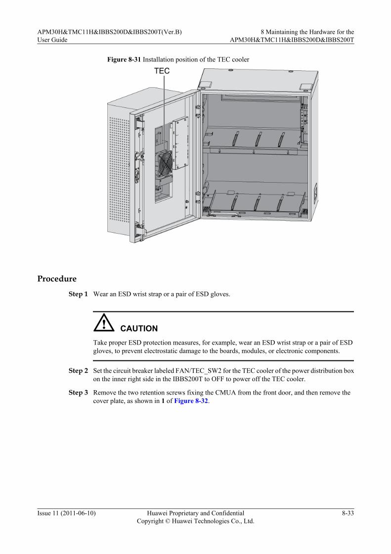
Figure 8-31 Installation position of the TEC cooler
Procedure
Step 1 Wear an ESD wrist strap or a pair of ESD gloves.
CAUTIONTake proper ESD protection measures, for example, wear an ESD wrist strap or a pair of ESDgloves, to prevent electrostatic damage to the boards, modules, or electronic components.
Step 2 Set the circuit breaker labeled FAN/TEC_SW2 for the TEC cooler of the power distribution boxon the inner right side in the IBBS200T to OFF to power off the TEC cooler.
Step 3 Remove the two retention screws fixing the CMUA from the front door, and then remove thecover plate, as shown in 1 of Figure 8-32.
APM30H&TMC11H&IBBS200D&IBBS200T(Ver.B)User Guide
8 Maintaining the Hardware for theAPM30H&TMC11H&IBBS200D&IBBS200T
Issue 11 (2011-06-10) Huawei Proprietary and ConfidentialCopyright © Huawei Technologies Co., Ltd.
8-33

Figure 8-32 Removing the retention screws from the CMUA
Step 4 Label the cables that connect the TEC cooler to the CMUA, and then disconnect the cables.
Step 5 Remove the two retention screws from the TEC protecting hood on the inner side of the frontdoor, as shown in 2 of Figure 8-32.
Step 6 Rotate the movable side of the TEC protecting hood clockwise by 90°. Remove the six retentionscrews, as shown in Figure 8-33, and then remove the TEC cooler from the subrack of the frontdoor.
Figure 8-33 Removing the faulty TEC cooler
8 Maintaining the Hardware for theAPM30H&TMC11H&IBBS200D&IBBS200T
APM30H&TMC11H&IBBS200D&IBBS200T(Ver.B)User Guide
8-34 Huawei Proprietary and ConfidentialCopyright © Huawei Technologies Co., Ltd.
Issue 11 (2011-06-10)
Step 7 Lead the power cables and the alarm signaling cables through the empty subrack on the frontdoor, and then install six M4 screws to fix the TEC cooler in the reverse direction in Figure8-33.
Step 8 Close the TEC protecting hood, and fix the hood using two screws.
Step 9 Connect the power cables and the alarm signaling cables that are delivered with the new coolerto the corresponding ports on the CMUA.
Step 10 Fix the CMUA using two screws.
Step 11 Set the circuit breaker for the TEC cooler of the power distribution box to ON.
Step 12 Check the running of the fans and the status of the LEDs on the CMUA to determine whetherthe new TEC cooler works properly. For details on the status of the LEDs, see CMUA.
Step 13 Take off the ESD wrist strap or gloves, and then pack up all the tools.
----End
Follow-up Procedurel Place the replaced module into the ESD box or bag. Then, place the ESD box or bag into
a carton padded with foam or into the packing box of the new module.l Fill in the fault form with the details about the replaced module.l Contact the local Huawei office to handle the faulty module.
8.13 Replacing the Fan on the Front Door of the IBBS200DReplace the centrifugal fan on the front door of the IBBS200D if it is faulty and cannot berepaired.
Prerequisitel The tools and materials, such as an ESD wrist strap or a pair of ESD gloves, Phillips
screwdriver, ESD box or bag, and key to the cabinet door are ready.l The quantity and model of the faulty fans are confirmed, and new fans of the same quantity
and model are ready.l The authorized personnel are permitted to enter the site. The required keys are available.
Contextl Figure 8-34 shows the installation position of the fan on the front door of the IBBS200D.
APM30H&TMC11H&IBBS200D&IBBS200T(Ver.B)User Guide
8 Maintaining the Hardware for theAPM30H&TMC11H&IBBS200D&IBBS200T
Issue 11 (2011-06-10) Huawei Proprietary and ConfidentialCopyright © Huawei Technologies Co., Ltd.
8-35

Figure 8-34 Installation position of the fan on the front door of the IBBS200D
l The fan box on the front door of the IBBS200D houses two centrifugal fans. When
maintaining the fan box, you need to replace only the faulty fan. This example describeshow to replace the fan on the left side.
l It takes about 20 minutes to replace the fan.
Procedure
Step 1 Wear an ESD wrist strap or a pair of ESD gloves.
CAUTIONTake proper ESD protection measures, for example, wear an ESD wrist strap or a pair of ESDgloves, to prevent electrostatic damage to the boards, modules, or electronic components.
Step 2 Set the circuit breaker labeled TEC/FAN_SW2 of the fan box to OFF on the power distributionbox in the IBBS200D to power off the fan box.
Step 3 Label the cables below the fan box, and then disconnect the cables.
Step 4 Remove the five retention screws from the fan box, and then remove the fan box, as shown inFigure 8-35.
8 Maintaining the Hardware for theAPM30H&TMC11H&IBBS200D&IBBS200T
APM30H&TMC11H&IBBS200D&IBBS200T(Ver.B)User Guide
8-36 Huawei Proprietary and ConfidentialCopyright © Huawei Technologies Co., Ltd.
Issue 11 (2011-06-10)

Figure 8-35 Removing the fan box from the IBBS200D
Step 5 Disconnect the cables that connect the faulty fan to one side of the CMUA.
Step 6 Remove the four retention screws from the faulty fan, and then remove the faulty fan from thefan box, as shown in Figure 8-36.
Figure 8-36 Removing the faulty fan
Step 7 Place the new fan in the original position of the faulty fan, and hold the fan with one hand. Then,tighten the four retention screws with the other hand using a screwdriver.
APM30H&TMC11H&IBBS200D&IBBS200T(Ver.B)User Guide
8 Maintaining the Hardware for theAPM30H&TMC11H&IBBS200D&IBBS200T
Issue 11 (2011-06-10) Huawei Proprietary and ConfidentialCopyright © Huawei Technologies Co., Ltd.
8-37
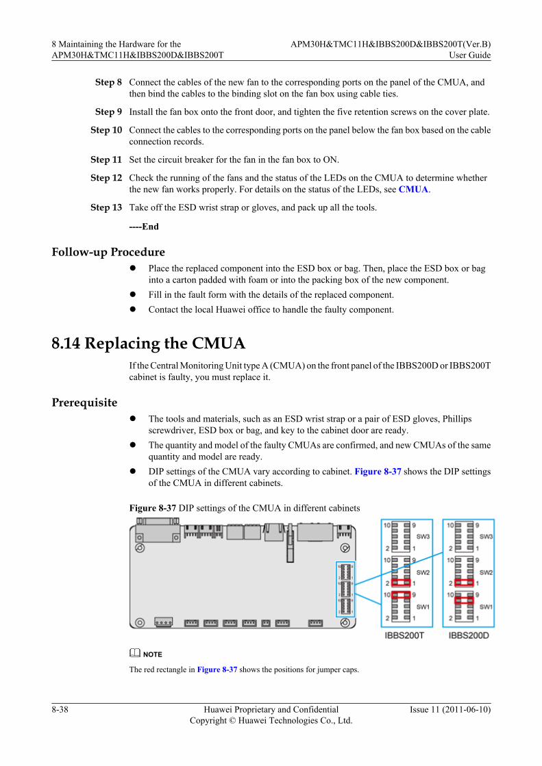
Step 8 Connect the cables of the new fan to the corresponding ports on the panel of the CMUA, andthen bind the cables to the binding slot on the fan box using cable ties.
Step 9 Install the fan box onto the front door, and tighten the five retention screws on the cover plate.
Step 10 Connect the cables to the corresponding ports on the panel below the fan box based on the cableconnection records.
Step 11 Set the circuit breaker for the fan in the fan box to ON.
Step 12 Check the running of the fans and the status of the LEDs on the CMUA to determine whetherthe new fan works properly. For details on the status of the LEDs, see CMUA.
Step 13 Take off the ESD wrist strap or gloves, and pack up all the tools.
----End
Follow-up Procedurel Place the replaced component into the ESD box or bag. Then, place the ESD box or bag
into a carton padded with foam or into the packing box of the new component.l Fill in the fault form with the details of the replaced component.l Contact the local Huawei office to handle the faulty component.
8.14 Replacing the CMUAIf the Central Monitoring Unit type A (CMUA) on the front panel of the IBBS200D or IBBS200Tcabinet is faulty, you must replace it.
Prerequisitel The tools and materials, such as an ESD wrist strap or a pair of ESD gloves, Phillips
screwdriver, ESD box or bag, and key to the cabinet door are ready.l The quantity and model of the faulty CMUAs are confirmed, and new CMUAs of the same
quantity and model are ready.l DIP settings of the CMUA vary according to cabinet. Figure 8-37 shows the DIP settings
of the CMUA in different cabinets.
Figure 8-37 DIP settings of the CMUA in different cabinets
NOTE
The red rectangle in Figure 8-37 shows the positions for jumper caps.
8 Maintaining the Hardware for theAPM30H&TMC11H&IBBS200D&IBBS200T
APM30H&TMC11H&IBBS200D&IBBS200T(Ver.B)User Guide
8-38 Huawei Proprietary and ConfidentialCopyright © Huawei Technologies Co., Ltd.
Issue 11 (2011-06-10)

l The authorized personnel are permitted to enter the site. The required keys are available.
Contextl Figure 8-38 shows the installation position of the CMUA on the front door of the
IBBS200D or IBBS200T.
Figure 8-38 Installation position of the CMUA
ProcedureStep 1 Wear an ESD wrist strap or a pair of ESD gloves.
CAUTIONTake proper ESD protection measures, for example, wear an ESD wrist strap or a pair of ESDgloves, to prevent electrostatic damage to the boards, modules, or electronic components.
Step 2 Set the circuit breaker labeled FAN/TEC_SW2 on the power distribution box to OFF to poweroff the CMUA.
Step 3 Record all the cable connections on the CMUA, and then disconnect all cables from the CMUA.
Step 4 Use a screwdriver to remove the screws from the fan box of the IBBS200D and from the CMUAbox of the IBBS200T, and then remove the fan box and CMUA box, as shown in Figure 8-39and Figure 8-40 respectively.
APM30H&TMC11H&IBBS200D&IBBS200T(Ver.B)User Guide
8 Maintaining the Hardware for theAPM30H&TMC11H&IBBS200D&IBBS200T
Issue 11 (2011-06-10) Huawei Proprietary and ConfidentialCopyright © Huawei Technologies Co., Ltd.
8-39

Figure 8-39 Removing the fan box from the IBBS200D
Figure 8-40 Removing the CMUA box from the IBBS200T
8 Maintaining the Hardware for theAPM30H&TMC11H&IBBS200D&IBBS200T
APM30H&TMC11H&IBBS200D&IBBS200T(Ver.B)User Guide
8-40 Huawei Proprietary and ConfidentialCopyright © Huawei Technologies Co., Ltd.
Issue 11 (2011-06-10)

Step 5 Label all the cables connected to the ports on the panel of the backplane of the CMUA, and thendisconnect the cable for the fans or the cable for the TEC cooler.
Step 6 Use a screwdriver to loosen the four retention screws from the four corners of the faulty CMUA.Remove the CMUA and place it into an ESD bag.
Step 7 Install the new CMUA in the fan box of the IBBS200D or in the CMUA box of the IBBS200T,and then use four retention screws to secure the board.
Step 8 Reconnect the cable for the fans or the cable for the TEC cooler to the ports on the panel of thebackplane based on the cable connection records.
Step 9 Reinstall the fan box and CMUA box on the front door of the IBBS200D and IBBS200Trespectively.
Step 10 Check the status of the LEDs to determine whether the new CMUA works properly. For detailson the status of the LEDs, see CMUA.
Step 11 Take off the ESD wrist strap or gloves, and then pack up all the tools.
Step 12 Attach the bar code delivered with the board to the cover plate. Figure 8-41 shows the positionsfor attaching the bar codes of the CMUA.
Figure 8-41 Positions for attaching the bar codes of the CMUA
----End
Follow-up Procedurel Place the ESD box or bag that contains the replaced board into a carton padded with foam
or into the packing box of the new board.
APM30H&TMC11H&IBBS200D&IBBS200T(Ver.B)User Guide
8 Maintaining the Hardware for theAPM30H&TMC11H&IBBS200D&IBBS200T
Issue 11 (2011-06-10) Huawei Proprietary and ConfidentialCopyright © Huawei Technologies Co., Ltd.
8-41
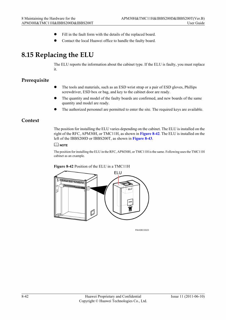
l Fill in the fault form with the details of the replaced board.l Contact the local Huawei office to handle the faulty board.
8.15 Replacing the ELUThe ELU reports the information about the cabinet type. If the ELU is faulty, you must replaceit.
Prerequisitel The tools and materials, such as an ESD wrist strap or a pair of ESD gloves, Phillips
screwdriver, ESD box or bag, and key to the cabinet door are ready.l The quantity and model of the faulty boards are confirmed, and new boards of the same
quantity and model are ready.l The authorized personnel are permitted to enter the site. The required keys are available.
ContextThe position for installing the ELU varies depending on the cabinet. The ELU is installed on theright of the RFC, APM30H, or TMC11H, as shown in Figure 8-42. The ELU is installed on theleft of the IBBS200D or IBBS200T, as shown in Figure 8-43.
NOTE
The position for installing the ELU in the RFC, APM30H, or TMC11H is the same. Following uses the TMC11Hcabinet as an example.
Figure 8-42 Position of the ELU in a TMC11H
8 Maintaining the Hardware for theAPM30H&TMC11H&IBBS200D&IBBS200T
APM30H&TMC11H&IBBS200D&IBBS200T(Ver.B)User Guide
8-42 Huawei Proprietary and ConfidentialCopyright © Huawei Technologies Co., Ltd.
Issue 11 (2011-06-10)

Figure 8-43 Position of the ELU in an IBBS200D or IBBS200T
Procedure
Step 1 Wear an ESD wrist strap or a pair of ESD gloves.
CAUTIONTake proper ESD protection measures, for example, wear an ESD wrist strap or a pair of ESDgloves, to prevent electrostatic damage to the boards, modules, or electronic components.
Step 2 Remove the RJ-45 connector from the port on the housing of the ELU.
NOTE
To replace the ELU in an IBBS200D or IBBS200T, remove the leftmost storage battery in the upper storagebattery compartment, as shown in Figure 8-44. For details about how to remove a storage battery, see 8.11Replacing the Batteries.
WARNINGPower off the storage battery before removing the battery.
APM30H&TMC11H&IBBS200D&IBBS200T(Ver.B)User Guide
8 Maintaining the Hardware for theAPM30H&TMC11H&IBBS200D&IBBS200T
Issue 11 (2011-06-10) Huawei Proprietary and ConfidentialCopyright © Huawei Technologies Co., Ltd.
8-43

Figure 8-44 Removing the upper-left storage battery
Step 3 Open the housing of the ELU upwards according to the direction displayed on the surface of thehousing, as shown in Figure 8-45.
Figure 8-45 Opening the housing of the ELU
Step 4 Use a Phillips screwdriver to loosen the screws on the ELIA. Remove the ELIA and place it intoan ESD bag, as shown in Figure 8-46.
Figure 8-46 Removing the faulty ELIA
8 Maintaining the Hardware for theAPM30H&TMC11H&IBBS200D&IBBS200T
APM30H&TMC11H&IBBS200D&IBBS200T(Ver.B)User Guide
8-44 Huawei Proprietary and ConfidentialCopyright © Huawei Technologies Co., Ltd.
Issue 11 (2011-06-10)
Step 5 Install a new ELIA, and then tighten the screws on the panel of the board.
Step 6 Reinstall the housing of the ELU.
Step 7 Re-link the RJ-45 connector to the port on the top of the housing of the ELU.
NOTE
For the IBBS200D or IBBS200T, reinstall the removed storage battery on the upper left. For details, see Installingthe Batteries and Related Cables.
CAUTIONPower on the storage battery after installing the battery.
Step 8 Take off the ESD wrist strap or gloves, and then pack up all the tools.
----End
Follow-up Procedurel Place the ESD box or bag that contains the replaced board into a carton padded with foam
or into the packing box of the new board.l Fill in the fault form with the details of the replaced board.l Contact the local Huawei office to handle the faulty board.
APM30H&TMC11H&IBBS200D&IBBS200T(Ver.B)User Guide
8 Maintaining the Hardware for theAPM30H&TMC11H&IBBS200D&IBBS200T
Issue 11 (2011-06-10) Huawei Proprietary and ConfidentialCopyright © Huawei Technologies Co., Ltd.
8-45