app note 119b - calinst.com · 1 compliance test system tutorial california instruments cts series...
TRANSCRIPT

1
Compliance Test System Tutorial
California InstrumentsCTS series
Compliance VerificationTutorial
ApplicationNote 119B
Harmonics
Flicker

2
Copyright 1998 - 2001, California Instruments

3
Compliance Test System Tutorial
Contents
Introduction ............................................................................................................................................. 5Power Quality and Standards ................................................................................................................... 6
IEEE-Std-519 , IEC555, EN61000-3-2/3 standards and Amendment 14 .................................................. 6The EMC Directive .............................................................................................................................. 6The impact of poor power quality ......................................................................................................... 7
Background on the EN61000-3-2 harmonics standard ................................................................................ 9Differences between IEC555.2 and EN61000-3-2 ............................................................................... 10EN61000-3-2 Amendment 14 Test Classes & Limit .............................................................................. 11True IEC-725 impedance or Programmable impedance option ............................................................. 13Test conditions and measurement methods ........................................................................................ 14Power source requirements for EN61000-3-2 ..................................................................................... 15
Impact of EN 61000-4-7 ......................................................................................................................... 16Background on the EN61000-3-3 Flicker Standard ................................................................................... 18
Human sensitivity to light flicker ......................................................................................................... 18Test conditions and measurement methods for Flicker ......................................................................... 19Power source for Flicker testing ......................................................................................................... 20The different types of Flicker testing ................................................................................................... 21CTS Flicker test data with synthetic impedance................................................................................... 21
CTS System configurations .................................................................................................................... 22Conclusions .......................................................................................................................................... 22
Appendix A: CTS Compliance Information .......................................................................................... 23Introduction ........................................................................................................................................... 23NPL Certified ........................................................................................................................................ 23EN61000-3-2 Compliance Testing ........................................................................................................... 23EN61000-3-3 Compliance Testing ........................................................................................................... 23
NIST traceability of Compliance Verification ........................................................................................ 24EN61000-3-2 Harmonics Compliance Verification of the CTS series ......................................................... 24EN61000-3-3 Flicker compliance Verification of the CTS series .................................................................. 27
Test results 5001iX-CTS system per IEC868 Amendm. I ...................................................................... 28AC Source Compliance .......................................................................................................................... 29
Voltage distortion limits ..................................................................................................................... 29Checking AC Source Distortion .......................................................................................................... 29Test Data for iX Series AC Sources .................................................................................................... 30
Conclusion ............................................................................................................................................ 30
Appendix B: High Power Complaince Test .......................................................................................... 32Introduction ........................................................................................................................................... 32Flicker testing per IEC 61000-3-11 .......................................................................................................... 32Harmonics testing per IEC 61000-3-12 .................................................................................................... 34High Power Solutions ............................................................................................................................. 34
4
This page intentionally left blank

5
Compliance Test System Tutorial
This tutorial provides a basic understanding and background for EN 61000-3-2 (harmonics) and EN 61000-3-3 Flicker (Voltage Fluctuations) testing withthe California Instruments Compliance Test System (CTS) series. Intimateknowledge of either IEC standard is not required to understand this applicationnote, as it reviews key requirements of these standards, and the tests to verifycompliance with these requirements. The European Union (EU) requires elec-trical products to pass a series of compliance tests, including harmonics, im-munity and in some cases Flicker testing. This application note discusses thestudies that resulted in the creation of the EN 61000-3-2 Harmonics - includingthe recently published Amendment 14 - and the EN 61000-3-3 Flicker standard- including Amendment 1.
This document also contains a description of the IEC-725 Reference Imped-ance and its purpose for Flicker testing. This lumped Reference Impedance,called OMNI, is available from California Instruments in both single and threephase versions. The single phase version can be integrated into the CTS hard-ware (option “-LR1”). Furthermore, the 5001iX power source offers programmableoutput impedance which can be set to the IEC-725 reference impedance values,or to the Impedance values required in Japan. There is an ongoing debate regard-ing the suitability of programmable (or synthetic) impedances for harmonics andFlicker testing. California Instruments conducted some comparative Flicker testswith the programmable 5001iX and with the OMNI (actual IEC-725 impedanceconsisting of resistors and inductors). This test data will be reviewed briefly,along with methods to verify performance of the CTS hardware and software.
Next, some cost considerations for EN 61000-3-2/3 testing will be discussed.Product development engineers and EMC professionals are concerned withescalating compliance testing cost, and the potential delays in product release.The California Instruments Compliance Test System (CTS) series representsa breakthrough in terms of technology and system cost. In addition, the powersource of the CTS can be used for AC and DC immunity testing and multipleother jobs in engineering, and the test software has general applicability inpower supply development efforts. A brief overview covering the various CTSconfigurations will be presented, which in turn allows the user to select theappropriate version and determine whether or not in-house (pre) compliancetesting is cost effective.
The CTS’ suitability for harmonics analysis in 100 - 120 Vac (60 Hz) applica-tions, such as found in Japan and the US, will also briefly be discussed. Sincethe CTS is a PC based system and generates test reports using MS Word,creating documents such as this application note is greatly facilitated and illus-trates the system’s value in power (supply) engineering tasks.
Finally, the implications of new standards for higher power harmonics andflicker testing up to 75 A RMS per phase per EN/IEC 61000-3-11 and EN/IEC61000-3-12 are discussed in Appendix B.
The reader may request a copy of the CTS 3.0 demo CD-ROM from CaliforniaInstruments. The CTS software supports a test file replay mode, which permitsthe user to view both harmonics and flicker tests as if they are performed in realtime. The demo disks contain actual test data files, thus permitting the user to“operate the system” on a PC without having the actual measurement hardwarein place.
Introduction

6
In the last two decades, the quality of electrical power has decreased invarious industrialized nations. This is primarily due to the increased use of elec-tronic equipment with so called nonlinear loads. These nonlinear loads causeharmonic currents, which in turn result in voltage distortion and subsequentlycause other equipment to fail or malfunction. Complaints from customers expe-riencing light flicker as a result of voltage fluctuations go back even further thanthe harmonics problems. Big arc welding equipment and industrial pressescaused consumers in Britain to complain to their utilities. Arc furnaces causedirritation in Germany, Japan and the UK. In Belgium, a lighting system of adance hall caused voltage fluctuations that in turn caused light flicker in privatehomes. As a result, the Union for International Electroheat (UIE) came up withguidelines for maximum allowable flicker levels. These, and other concerns aboutpower quality, eventually found their way into national and international stan-dards.
In the USA, the IEEE-Std-519 was first released in 1981, and the 1992 revi-sion is widely used as a guide to control harmonics in electrical power systems.This standard covers recommended practices and requirements for harmoniccontrol in electrical power systems, and mainly addresses harmonics, althoughFlicker issues are discussed as well. The International Electrotechnical Com-mission (IEC) released standards dealing with low voltage public supply systemquality as well. The first edition of IEC 555-2 (harmonics) dates back to 1982,and IEC555-3 (voltage fluctuations or Flicker) came shortly thereafter. Subse-quently, these two standards were revised multiple times, and finally released inthe early 1990’s as IEC 1000-3-2 (harmonics), and IEC 1000-3-3 (Flicker). Thelatest revision of the Harmonics standard is EN 61000-3-2 Am14 effective Jan1, 2001. The latest revision of the Flicker standard is EN 61000-3-3 Am1 and iseffective as of November , 2000. The Flicker standards are based on a UIE/IECreport which found its way into a standard document called IEC 868, which inturn was approved as Euronorm EN 60868-0 by CENELEC on December 9,1992. Most electrical apparatus sold within the member countries of the Euro-pean Union (EU) have to meet the requirements of these IEC standards, asgoverned by the EMC directive.
IEC standards, although of worldwide importance, do not have the legal forceof law unless accompanied by some national standard. In Europe, the EU issuedthe Electro Magnetic Compatibility (EMC) directive in order to unify rules andregulations in the member states. In the context of the EMC directive, the EUrequires member countries to issue identical National Standards after CENELEC(Commité Europeén de Normalisation Electrotechnique) approves a EuropeanStandard. CENELEC membership includes the EU, Switzerland, Finland, andIceland. Note that the EMC directive is much broader than just Harmonics andFlicker, and covers all electrical emissions and susceptibility aspects. Stan-dards specify how much radiated and conducted electromagnetic emissions aproduct may cause. Other standards govern immunity i.e. a product’s suscepti-bility to the radiated and conducted emissions from other electrical devices.
For harmonics and Flicker, the relevant European standards are derivedfrom the IEC 61000-3-2/3 versions, and are numbered EN 61000-3-2 (super-seding EN 60555.2) and EN 61000-3-3 (superseding EN 60555.3). The indi-vidual member countries of the EU are required to issue identical national stan-dards within 2 years after the European standard is formally published/announcedin the official European Journal. Note that Europe is also in the process of uni-fying the electrical power systems of all countries to 230 Vac - 50 Hz. The IEC
Power Quality andStandards
IEEE-Std-519 , IEC555,EN61000-3-2/3 standardsand Amendment 14
The EMC Directive

7
Compliance Test System Tutorial
standards therefore primarily concentrated on 230 Vac - 50 Hz, and provisions forother line voltages and frequencies are under consideration.
Japan has adopted a national standard which differs from the IEC 61000-3-2/3 documents, as their power distribution differs significantly from the Europeansystem. While compliance with this harmonics standard is not mandatory, thereis strict cooperation between industry, government and the utilities to make sureall new products placed on the market comply with the Japanse version of EN61000-3-2. The CTS System supports testing to this standard as well.
Even though the IEEE-Std-519 provides some guidance, it is likely that theUS will also adopt modified versions of EN 61000-3-2/3 in the future. Some effortswere already made to harmonize Amendment 14 of the EN 61000-3-2 standardwith a possible new IEEE harmonics standard. In particular the common 200msec acquisition window for evaluation of current harmonics for both 50 Hz and60 Hz products will contribute to this harmonization.
The IEC standards in question deal with single and three phase electricalequipment having a current level of < 16 Amp rms. Most 230 Vac - 50 Hz house-hold electrical equipment, test and measuring instruments, information technol-ogy products, consumer electronics, and lighting products, consume well below16 Amperes. Thus the EN 61000-3-2/3 standards cover all these products. Be-cause so many of these products utilize switching power supplies, they have atendency to induce harmonics in the power distribution system. This can causeoverheating in neutral lines, and can also be very detrimental to transformersand motors. To understand the negative impact of harmonics, the example of asimple 17 inch VGA monitor can be used.
The impact of poorpower quality
Figure 1

8
Figure 1 shows a screen capture of the voltage and current waveform of this17 inch VGA monitor operating on 230 Vac - 50 Hz. The CTS system displaysthese waveforms and harmonic levels on the PC screen, along with the relevantpower parameters and test conditions. Many TV’s would exhibit a similar behav-ior, although their power level will generally be higher (for the larger screen sizes).Note that the electrical current (top graph) is drawn in almost pulse-like fashion,during only part of the half cycle. This behavior is typical of switching type powersupplies, such as those used in TV’s, monitors, audio systems, microwave ov-ens, printers, copiers, video games, etc. Note that the monitor consumes about146 Watts and requires 0.995 Arms from the 230 Vac power distribution sys-tem. Its peak current demand is in excess of 2.818 Amperes, however. This“peaky” current waveform produces a lot of harmonics, which are shown in thebottom graph (bar), although they do not exceed the limits for Class-D typeequipment (limit line in the bottom graph of Figure 1).
The CTS also stores and displays the test data in numerical or tabular format.Figure 2 shows the tabular display of the current harmonics recorded from adifferent VGA monitor by the CTS program. It shows that the 3 rd harmoniccurrent level at 0.540 Amp is 87.5 % of the fundamental current level (0.617Amp). As 3rd harmonic currents do not cancel out in neutral conductors, it caneasily be understood that the neutral lines in an office building (with many moni-tors and PC’s) can carry very high current levels, and thus potentially overheat.
Figure 2

9
Compliance Test System Tutorial
Transformers may also overheat due to harmonic, currents and motors areaffected negatively as well. Several of the higher harmonics have what is knownas a negative phase sequence which can cause torsional vibrations in motors,and higher frequency losses may cause windings to overheat. Excessive har-monics therefore can affect several types of critical electrical equipment. Fig-ure 3 shows the current waveform graph in more detail. Voltage and currentwaveform data for every acquisition window can be saved during each test. Alldata is written concurrently. The CTS can record a full measurement / analysisdata set AND the associated voltage and current waveforms every 320 ms or200 msec. One of the requirements stated in EN 61000-3-2 Amendment 14, isthat transitory harmonic testing must be done over 10 or 12 cycles (200 ms ateither 50 of 60 Hz) without permitting gaps in the measurement process. Thisno-gap requirement is to make sure that the analysis “catches” the worst caseconditions, as transitory harmonics may come and go. By saving all acquiredcycles to disk, the CTS software ensures complete archiving of all test data.
Therefore, the system not only performs a compliance test but also servesas an engineering data collection tool. The CTS file replay mode permits theuser to inspect the behavior of the tested unit. In this mode, the test files can bestepped one measurement window at a time. As done for this document, testdata files can be converted from their native binary files to ASCII text files foruse in word processors and spreadsheets as desired.
There are numerous case histories of serious problems caused by exces-sive current harmonics. Transformer overheating is probably one of the morecommon events. Transformer failure in turn leads to power outages for wholeneighborhoods and/or factories and businesses. Some events can even upsetthe control system of the high voltage grid, leading to widespread power failureswhich include many states or even sections of a country. Overheated neutrallines have caused fires in office buildings, and sensitive electronic equipmenthas failed because of short voltage dips caused by other “misbehaved” electri-cal equipment. As electrical power has become such an integrated part of ourlife, standards to assure its quality have become just as necessary as safetystandards.
Background on theEN61000-3-2 harmonicsstandard
Figure 3

10
As mentioned earlier, harmonic currents have negative effects on electricalequipment. Efforts to limit harmonics and set some standards date back to the1930’s. The International Electrical Committee’s (IEC) Technical Committee77 (TC77) formulated its concept for a standard covering current harmonics atmeetings held in Moscow (1977) and The Hague (1979). This work culminatedin IEC 555.2, first published in 1982, and revised in 1984, 1986, and 1991. Inthe process, a Euro Norm called EN 60555.2, based on one of the intermediaterevisions, was released. In December 1993, TC77A submitted a further revi-sion document, known as Central Office no. 41 (CO-41), for approval. Thisdocument was approved by a majority of IEC member countries, and thusbecame EN 61000-3-2. The standard is also referred to as IEC 61000-3-2 andis identical to CO-41. We will use the official EN 61000 designation in thisdocument.
Euronorm EN 61000-3-2 and the national counterparts, are legally enforce-able versions for the EU countries. There are European Standards for just aboutevery type of consumer product, from toys to tools and electrical apparatus.After passing the applicable tests, the manufacturer is entitled to attach a socalled CE mark, approving the product for sale throughout the European Union.Once the CE mark is obtained, a manufacturer no longer has to pass testing ineach individual country. In practice, things don’t work smoothly yet, as the EUhasn’t totally completed its internal harmonization process. One example is theenforcement date for EN 61000-3-2 3 (IEC 61000-3-2) for harmonics testing.The original goal was to have the new standards in force throughout Europe byJan. 1, 1996. This later became Jan. 1, 1997, and then August 1998. Somecountries (manufacturers) complained that they would not be able to meet themore aggressive time tables, which caused the mandatory enforcement datesto be shifted. This ultimately resulted in publication of Amendment 14, which isnow applicable throughout the CENELEC countries, even though the prior (lastrevised in 1998) version of the EN 61000-3-2 standard may be used until Janu-ary 1, 2004.
The intent of the EN 61000-3-2/3 standards is to force manufacturers toproduce products that “behave well” when connected to the supply system.This implies that the electrical system quality is not deteriorated beyond speci-fied limits by the operation of the electrical product. Electrical products have tobe tested to verify conformance with specific limits. As the EC has made con-formance to EN 61000-3-2/3 mandatory, product testing to these standards hasbecome mandatory as well. Note that these “product power quality” standardstherefore are aimed at preventing power quality deterioration.
The IEEE-Std-519 (1992) is more comprehensive in its approach, but wasnot intended as a product testing standard, as it deals with power quality issuesin a much broader sense. Its origins go back to the 1970’s, with the first versionbeing published in 1981. Product testing standards for the US are expected toevolve in the next couple of years. The EU had the short term demand to unifytesting standards amongst member countries and, as such, is a few years aheadof the US and Japan, in the process of ensuring future quality of householdpower distribution systems. The publication of Amendment 14 of the EN 61000-3-2 standard covering both 50 and 60 Hz is an important step toward harmoni-zation of standards between Europe, the USA and Japan.
Differences betweenIEC555.2 andEN61000-3-2

11
Compliance Test System Tutorial
The differences between EN 60555.2 and EN 61000-3-2 touch mainly on threeareas. These are the scope/applicability of the standard, the fact that IEC 555.2did not have a Class-D category, and the slightly different limits for Class-C (light-ing products). From the early days of IEC 555.2, the standard was directed mainlytowards products “purchased by the general public” in other words consumerproducts. Initially, professional products with a limited customer base were ex-cluded. The CO-41 document changed this scope to include all electrical prod-ucts with a rated current of up to 16 Amperes per phase. Therefore, most test &measurement equipment, communications gear, and industrial products, fall withinthe scope of EN 61000-3-2.
The broader scope of EN 61000-3-2 is especially important for InformationTechnology (IT) equipment. Products like PC’s and fax machines were deemedprofessional products only 10 years ago, while they are consumer productstoday. The wording of EN 61000-3-2 removes the interpretation ambiguity thatIEC 555.2 permitted. Whereas IEC 555.2 had a separate test class for TV’s,this category (with some modifications) was expanded into a family of Class-Dproducts in the new EN 61000-3-2. Since this class D covered a broad scope ofproducts and it’s limits are a function of the power level, many products wereunable to meet this new requirement. Based on industry pressure, the IECpublished Amendment 14 to the standard, which considerably narrows the rangeof products that have to meet class D limits.
The standard defines four (4) test classes, Class-A, B, C, and D, each havingtheir own harmonic current limits. Classes B, C, and D describe specific prod-ucts and product families, and all other products and motor driven equipment areautomatically categorized as Class-A equipment.
The limits for Class-A and Class-B equipment are given in Amp rms (and so isthe TV category of IEC 555.2). Class-C and Class-D limits vary with the powerlevel of the tested product. Other than the 2nd harmonic in Class-C, there are nolimits for even harmonics in either Class-C or D. Also, the 3rd harmonic limit ofClass-C depends on the product’s power factor. The limits for each class, includ-ing the TV category of IEC 555.2, are shown in Table 1.
Class-A includes all motor driven equipment, many domestic appliances,and 3 phase equipment.
Class-B includes all portable electric tools operated directly from 230Vac - 50 Hz.
Class-C includes all lighting products, including dimming devices, withinput power > 25 WattsNote that EN 61000-3-2 was also amended to include limits on lowpower lighting products below 25 Watts (Compact FluorescentLamps). For these products, the 3rd harmonic current must be < 86%and the 5th harmonic current must be < 61% of the fundamentalcurrent.
Class-D includes PC’s, PC Monitors and Televisions with a rated powerlevel between 75 and 600 Watt.
Note that the current waveform envelope that used to apply under the previ-ous EN 61000-3-2 Harmonics standard for Class-D equipment as shown inFigure 4 (copied from the CTS screen for the 17” monitor test) has been elimi-nated with the publication of Amendment 14. The CTS system still allows test-ing to the old standard if desired, in which class an automatic class A versus Devaluation takes place and the operator is informed accordingly.
EN61000-3-2 Amend-ment 14 Test Classes &Limit

12
Table 1 Harmonic Class - A Class-B Class-C Class-D IEC555.2no. (n) limits limits limits limits limits for
(both (both IEC1000-3-2 IEC1000-3-2 TVstandards) standards) only only receivers
(> 165 Watt)% of mA/Watt (max
fundamental of input dc current(PF= power power < 0.05 A)
A rms A rms factor) (75 - 600 W) A rms
2 1.080 1.620 2 % n/a 0.3003 2.300 3.450 30 x PF % 3.4 mA/Watt 0.8004 0.430 0.645 n/a n/a 0.1505 1.140 1.710 10 % 1.9 mA/Watt 0.6006 0.300 0.450 n/a n/a n/a7 0.770 1.155 7 % 1.0 mA/Watt 0.4508 0.230 0.345 n/a n/a n/a9 0.400 0.600 5 % 0.5 mA/Watt 0.300
10 0.184 0.276 n/a n/a n/a11 0.330 0.495 3 % 0.35 mA/Watt 0.17012 0.153 0.230 n/a n/a n/a13 0.210 0.315 3 % 0.296 mA/Watt 0.120
Even 1.84 /n 2.760 /n n/a n/a n/a14 - 40
Odd 2.25 /n 3.375 /n 3 % 3.85/n 1.5 /n15 - 39 (mA/Watt) (Amp)
Figure 4
Figure 5

13
Compliance Test System Tutorial
Figure. 4 shows the voltage (sinusoidal) and current waveform (peaky) of atypical EUT. The test class selection is made by the operator in the setup screenas shown in Figure 5. Note that under the new Amendment 14, the class Dcurrent template is no longer relevant to determine if an EUT is a class D prod-uct. Instead, only TV’s, PC’s and PC Monitors are class D if the rated power levelis within the 75 - 600 Watt range and the measured power during the test is within10 % of the rated power level stated by the manufacturer. If not, the EUT may betested to Class-A limits. Alternative interpretations stipulate that no limits applyto class D products that don’t meet the rated power level. In that case, no pass/fail analysis is done if the average power level is below the 75 W threshold. TheCTS system can accommodate either method if desired.
Even though the CTS is available for different power levels, the operation isidentical, irrespective of the power source type. In other words, operating the1251RP-CTS is similar to the 5001iX-CTS. The only difference between the 1251RPand the “iX” is that the “iX” series permits the user to program a test impedance,while the 1251RP does not have this feature. The “iX” offers added flexibility,especially for users who have to test against the European EN 61000-3-2 andagainst the Japanese version with the same system.. Whereas the EN 61000-3-2 specifies a measurement circuit without a Reference Impedance (see nextsection), the Japanese version requires the use of a Reference Impedance whendoing harmonics testing. Moreover, the impedance level for testing per the Japa-nese version changes, depending on the test voltage and circuit type. Thesedifferent impedance levels reflect the Japanese power distribution system. The‘Japanese’ limits selection in the CTS setup screen selects this Japanse methodof harmonics testing.
When the test circuit for the EN 61000-3-2 was determined, the approachwas to make sure that harmonics were acceptable, even in the worst casecondition. As the Reference Impedance has an inductive element, it tends tosuppress the level of higher frequency harmonics. By eliminating the imped-ance therefore, the EUT is permitted to induce a higher level of harmonic cur-rents than would be the case if the device was connected to the power outlet in ahome. The Japanese have taken what some describe as a more pragmatic ap-proach, by permitting the reference impedance to be in the test circuit for har-monics testing.
True IEC-725impedance orProgrammableimpedance option
Figure 6 Figure 7

14
The old EN 61000-3-2 standard defines two basic test conditions, SteadyState and Transitory (Fluctuating) State. Under Amendment 14, all products areevaluated using the transitory method. A further complication is caused by thefact that the limits for Class-C & D are proportional, as earlier explained. Whereasthis does not cause any difficulties for products with a constant current/powerlevel, the situation is less clear for products with fluctuating load levels. Most testsystems implement so called dynamic limits, with the limits constantly beingadjusted per the measured power (or the fundamental current for Class-C) whileothers use some average power level to set the limits. The latter systems deter-mine this average power/current using some arbitrary method, and pre-test pe-riod. Thus different test systems implement different limits for the same (fluctuat-ing power) products, which can result in one system PASSING a product whilethe other REJECTS it. Under Amendment 14, the manufacturer rated power levelor current is used to determine class C and D limits, eliminating this issue.
A second issue for fluctuating loads is the way the previous harmonics stan-dard (second edition) defined criteria for passing and failing the harmonics test.The old standard permitted the unit under test to occasionally exceed the 100 %limit, provided the harmonics never exceed 150 % of the limit. In fact, the unitunder test was allowed to exceed the 100 % level for 10 % of the test time. Thetest time for fluctuating loads has to be at least 2.5 minutes, i.e. the harmonicscan exceed the 100 % limit for 15 seconds in every 150 second (2.5 min) pe-riod. For longer test times, one can perform this test in 2.5 minute “time blocks”but another interpretation is to take just 10 % of the overall test time. Thus, thetesting method for fluctuating loads is, to some extent, subject to interpretationby the test equipment manufacturer. The new Amendment 14 version of the Har-monics standard now requires the following limit evaluation:
The average value for the individual harmonic currents, taken over theentire test observation period shall be less than or equal to the appli-cable limits.
For each harmonic order, all 1.5 sec. smoothed r.m.s. harmonic currentvalues shall be less than or equal to 150% of the applicable limits.
Harmonic currents less than 0,6% of the input current measured underthe test conditions, or less than 5 mA, whichever is greater, are disre-garded.
For the 21st and higher odd order harmonics, the average values ob-tained for each individual odd harmonic over the full observation pe-riod, calculated from the 1.5 s smoothed values may exceed the appli-cable limits by 50% provided that the following conditions are met:
- The measured partial odd harmonic current does not exceed thepartial odd harmonic current which can be calculated from theapplicable limits.
- All 1.5 s smoothed individual harmonic current values shall beless than or equal to 150% of the applicable limits.
Test conditions andmeasurementmethods

15
Compliance Test System Tutorial
Note that many existing Harmonics and Flicker test systems may requirefirmware and or software upgrades to conform to Amendment 14. Existing CTSusers can upgrade by simply installing CTS software version 3.0. No firmware orhardware upgrades are needed for full compliance with Amendment 14.
The standard further describes general test conditions and measurementmethods. Basically, the general test conditions are selected to ensure that theworst case harmonics are evaluated. In other words, the test has to include alldifferent operating conditions for the EUT. The EN 61000-3-2 test is to be per-formed over a full operating cycle of the tested equipment. For fluctuating analy-sis, the minimum test period is still 2.5 minutes, or 150 seconds. If a full operat-ing cycle takes 2 hours, the test period becomes at least 2 hours as well. Duringthe harmonics test, the analysis has to be performed without any gaps in themeasurement. Transitory harmonics testing (fluctuating analysis) requires analy-sis to be done every 200 ms (10 cycles at 50 Hz or 12 cycles at 60 Hz). The CTSdoes exactly that, and also writes the test results along with waveform data todisk. Therefore, the CTS program produces a 2.5 minute test file with 750 rowsof data, 5 for every second. Note that the old standard may be selected if neededin which case the acquisition window used is 16 cycles (320 msec) and 3 to 4records per second will be written to the test data file..
For longer tests, every 200 msec or 320 ms acquisition window is evaluated,but not every data set is written to the test file, unless limits are exceeded. If theequipment under test exhibits harmonics that exceed the limits, the CTS willwrite a number of data windows before the limit violation and a number of datawindows after to disk at full speed, and then revert back to a slower recordingrate. This implementation provides both pre and post event data while prevent-ing excessive data file sizes.
Naturally, the power source is not allowed to affect the current harmoniclevels. Since the “ideal” power source doesn’t exist, the EN 61000-3-2 standardimposes certain minimum power quality requirements in Annex A. Probably themost demanding requirement is that the voltage distortion must remain verylow, even when testing a nonlinear load with high harmonic current content asdepicted in Figure 1.
Maximum permitted H2 - H40 voltage distortion with EUT connected in nor-mal operation ;
0.9 % for harmonic of order 30.4 % for harmonic of order 50.3 % for harmonic of order 70.2 % for harmonic of order 90.2 % for even harmonics of order 2 - 100.1 % for odd harmonics of order 11 - 40
The CTS performs a continuous voltage quality check, to make sure thatcurrent harmonic levels are not affected. The “VTHD” indication (see Figure 1,page 7) indicates the voltage quality, and the test file is updated every 200 ms or320 ms. with the same indication. Obviously, if current harmonics are 5 x theallowable limit, voltage quality doesn’t matter very much. It’s mainly for borderlinecases where voltage distortion matters.
Power sourcerequirements forEN61000-3-2

16
The standard covers equipment with current levels up to 16 Amp rms. Includ-ing the maximum harmonics per Class-B (Transitory), peak currents can be about40 Amperes, hence the source must be able to deliver this power level. Forsystems that need to accommodate all types of EN 61000-3-2/3 testing, thishigher current level needs to be taken into consideration. For testing specificproducts like TV sets or video recorders, the power source can be much smaller,like the 1251RP-CTS which handles 1250 VA and supports peak currents up to13.8 Amp.
The standard also requires that the measurement circuit itself has minimaleffect on the harmonic analysis, i.e. low source impedance, negligible voltagedrop across shunts, high accuracy measurements, etc. The test circuit given inAnnex - A of the standard is shown in Figure 6 on page 13. The CTS is providedwith dual active HALL effect CT’s, having virtually no voltage drop in the measure-ment system. The CTS signal conditioner isolates and scales the measurementsignals and routes them to the DSP based analysis subsystem inside the PC.This analysis subsystem consists of a specialized plug-in card that requires aPCI expansion slot in the PC. The higher power CTS configurations with the “iX”source have been tested under worst case harmonics conditions (> 40 amppeak), and even then maintain very low voltage distortion, hence produce reli-able harmonic analysis. The CTS can either bypass the impedance (OMNI) forharmonics tests, or insert the impedance as is required for Flicker testing.
To complicate matters further, the new Amendment 14 replaces Annex-B ofthe old 61000-3-2 standard with a reference to the EN 61000-4-7 Harmonicmeasurement standard. This standard deals with the method for acquiring andanalyzing current harmonics. A new version of this standard is expected to bereleased in early 2002 which will now include interharmonics in addition to har-monics. This will require the inclusion of interhamonics in the evaluation of theEUT current against the class limits. For most harmonics and flicker systems,this will have a significant impact on the way data is acquired and processed.The DSP subsystem in the PC used by the CTS samples at very high rates, inexcess of 200 kHz depending on the configuration, and thus can be used toproduce accurate waveform and harmonic analysis, including interharmonics.This capability has been incorporated in revision 3.0 of the CTS software andcan be enabled by the operator at any time. Note that the interhamoncis data ismerged with the integer harmonic data as explained below and thus is not dis-
Figure 8
Impact of EN61000-4-7

17
Compliance Test System Tutorial
played separately. Per the new EN 61000-4-7 standard, interharmonics are “lumpedin” with the (integer) harmonic subgroup level using a precisely specified algo-rithm. Although interharmonics may not necessarily have the cumulative effect asis the case with odd triplens (3rd, 9th , 15th, etc) they do generate heat, andadversely affect electrical gear. Hence the interharmonics are lumped into theadjacent integer harmonic level using the geometric averaging algorithm, similarto a RMS calculation, as given in Figure 8. This geometric average of the har-monic subgroup is filtered (using the 1.5 sec filter) and then compared against theapplicable limits. The new standard also defines the algorithm to calculate justthe interharmonic subgroup (see figure 8). Note that if the 16 cycle acquisitionwindow were to be used, the algorithms would change somewhat, as the numberof interharmonics from the FFT would differ. This is reflected in the different algo-rithms. Figure 8 shows the algorithm for a 200 msec. acquisition period as usedby the CTS system and the graphical representation of this concept for a 50 Hzpower system.
CENELEC Amendment-14 to EN 61000-3-2 moves many electronic productsfrom test Class-D to the generally more relaxed Class-A. For remaining class Dproducts, limits are now based on the manufacturer’s “rated” power. This ratedpower is to be determined in accordance with the 1.5 sec filtered measurementmethod as given in the amendment. The same method applies to determine theFundamental Current and Power Factor for Class-C products. The amendmentdefines measurement methods and harmonic limit comparisons that apply toboth stationary and fluctuating harmonic analysis. Per the amendment, the nor-mative Annex-B of EN 61000-3-2 is to be replaced by the measurement andanalysis methods given in (the new) EN 61000-4-7. This new standard requiresthe use of a 200 ms acquisition window, and specifies algorithms to includeinterharmonics into the so called harmonic subgroups. The CENELEC Amend-ment therefore greatly affects compliance test systems. Especially manufactur-ers of Class-D products need to implement the new methods to determine what“rated” power levels they need to specify for their products. This applies also tomanufacturers of lighting products (Class-C) for fundamental current and PF aswell. Testing authorities and test laboratories should also take the changing re-quirements of EN 61000-4-7 into consideration. The CTS system is fully capableof supporting these new requirements.
Figure 9
18
As the name indicates, the Flicker standard evolved from the requirement toreduce voltage fluctuations that cause irritating light flicker. Most of the com-plaints concerning light flicker were caused by heavy duty industrial equipmentlike arc furnaces. Products such as electrical welding machines, air condition-ers, water heaters, and even bigger lighting systems can cause these voltagefluctuations. While the initial study mainly concerned voltage fluctuation levelsat the point of common coupling (PCC) in electrical power distribution systems,the scope was later broadened to define acceptable fluctuation levels at theconsumers premise.
To determine acceptable voltage fluctuation levels, a large group of individualswas subjected to light flicker from the so called 60 Watt - 230 Vac -50 Hz refer-ence lamp. The supply voltage to the lamp was varied to cause light flicker ofdifferent magnitudes and frequencies, and people would indicate when a givenlevel was irritating. It turned out that the human eye-brain system has a particularsensitivity curve. Just as our hearing is most sensitive in the frequency range of1000 - 4000 Hz, and tapers off fairly quickly for frequencies outside this range, wehave a similar response to light flicker. This sensitivity curve is shown in Figure 9on page 17. The percentage voltage change is given in percent on the verticalaxis, and rate of change in cycles per minute (CPM) is given on the horizontalaxis. The line in Figure 9 is known as the standard perceptibility curve, indicatinga perceived flicker level of one (1.00). The “Pst” stands for “Perceptibility-shortterm”, short term being 10 minutes in this case. The human eye-brain system ismost sensitive for light intensity changes that occur at the rate of about 1052changes per minute, or 8.77 Hz. Intensity changes of 3 % once a minute causethe same irritation level as a 0.3 % change at a rate of 8.77 Hz.
This Pst level of 1 was determined to be the threshold of irritability for theaverage human. Note that a single change of 3 % in a 10 minute period consti-tutes much less than a Pst of 1. As is easy to understand, the light flicker needsto repeat in order to become irritating. In other words, Flicker has a cumulativeeffect. After determining the human sensitivity curve, a measurement and evalu-ation method was developed to translate voltage fluctuation percentage andfrequency into Pst. The methodology to evaluate voltage fluctuations was pub-lished in the form of IEC 868, and Amendment I to this standard. It describesthe Laplace transfer function, used to convert the two variables (percentageand frequency) into instantaneous perceptibility “P”. The Perceptibility numberfor every measurement (100 times per second) is categorized into classes, andthrough a Cumulative Probability Function (CPF) converted into Pst for every10 minute observation period. So, when the IEC 555.3 standard was publishedit basically specified that electrical equipment should not be permitted to causevoltage fluctuation patterns which would result in flicker levels which humansperceive as irritating. The IEC 868 Flicker Meter method was specified as thestandard method to calculate the Pst level.
As IEC 868 was amended and more experience gained, a long term Flickerevaluation was devised. This parameter is called Plt (Perceptibility long term),and is evaluated over a period of 2 hours. Whereas the maximum permitted Pstis 1.00, the highest allowed level of Plt is 0.65. In plain English; the averagehuman can handle light flicker with a Pst value of up to 1 for 10 minutes, but ifthis continues for 2 hours at a level of 0.65, we still get irritated. Also, it wasdetermined that electrical products should not be so “misbehaved” that theycause an instantaneous voltage drop (“dmax”) of more than 4 %, other thanwhen turned on the first time.
Human sensitivityto light flicker
Background on theEN61000-3-3Flicker Standard

19
Compliance Test System Tutorial
Finally, products cannot be allowed to cause the line voltage to drop in ex-cess of 3 % for more than a second. The parameters to check the voltage dropare called “dt” and “dc” respectively. The “dc” parameter is referred to as “steadystate voltage drop”. Amendment 1 to the EN 61000-3-3 Flicker standard in-creases the dc limit from 3.0 % to 3.3 %. Furthermore, the permissible dmax forcertain types of products such as portable power tools has been increased aswell. These changes took effect in late 2000 and are fully implemented in revi-sion 3.0 of the CTS software.
The basic measurement for Flicker is theRMS voltage level per half cycle of the 50 Hzfundamental frequency. Thus, the RMS levelis measured 100 times per second. “dt’ is thechange in percent (relative to 230 Vac) betweensuccessive half cycles. Flicker impression “P”is calculated from “dt” and then Pst is computedfor every 10 minutes. Plt in turn is computedover 12 successive Pst measurements. Forproducts that are tested for periods less than 2 hours, because their operatingcycle lasts less than 2 hours, the Plt computation is still averaged over 2 hours.The calculation is done on the basis of a cubed averaging algorithm, as shownhere.
Depending on the test duration, “N” can be from 1-12 Pst measurementvalues (called Psti in this case). For example, after the first Pst measurement of0.95, the resulting Plt will be the cubed root of 0.95 3/12 which equals 0.0714 1/3 or 0.415 . If this level were to persist for 40 minutes, the Plt will be the cubedroot of 4 x 0.95 3 / 12 which equals 0.66, thus exceeding the 0.65 limit.
Figure 10 illustrates the CTS Flicker replay display at the instant a switchingpower supply is turned on. The graph shows the voltage drop of 3.9 % (acrossthe Reference Impedance) due to the inrush current of the supply, and then thereturn to 230 Vrms. The total event which happened about 2 minutes into thetest, takes only about 3 half cycles or 30 milliseconds. The graph displays 100values i.e. covers a measurement period of 1 second.
Figure 11
Test conditions andmeasurementmethods for Flicker

20
For the Flicker test, the IEC 725 reference impedance is inserted into the testcircuit as shown in Figure 11. The values for RA , XA , RN , and XN , are given inIEC-725 and also in EN 61000-3-3. For single phase testing, it is permitted tolump the resistive elements together (0.24 + 0.16) for a total of 0.4 Ohm andcombine the inductive elements (0.478 + 0.318 mH) for a total value of 0.8 mH.
These impedance values differfor testing to the Japanese version.For current levels < 20 Amp in a 2wire 100 V test, the total resis-tance is 0.4 Ohm, but the induc-tance is only 0.37 mH. For a 2 wire200 Volt test, the resistance is0.38 Ohm and the inductance 0.46mH. These values include thesource impedance, thus the OMNIreference impedance and thesource output impedance consti-tute a matched system.
Even though the Reference Impedance values include the output impedanceof the power source, it is imperative that the source have excellent power qualityand a low output impedance. In fact EN 61000-3-3 provides some specific param-eters under the heading “Test Supply Voltage”. The standard states that the testvoltage must be maintained within 2 % of the nominal value (under constant load)and that the total harmonic distortion shall be less than 3 %. If the measured Pstlevel is less than 0.4, any fluctuations of the supply voltage may be ignored. Thespecific overall measurement accuracy for Flicker parameters is +/- 8 %. Thisincludes all errors, including those caused by deviation in the Reference Imped-ance and/or output impedance of the source. Consequently, it is important tokeep the source impedance and all interconnect wiring resistance as low aspossible. Again, the source with the CTS signal conditioning shown in Figure 11consists of a matched system and, therefore, provides the basis for accurateFlicker analysis.
Power source forFlicker testing
Figure 10
Figure 11

21
Compliance Test System Tutorial
Similar to the harmonics standard for Flicker testing, the product is to beoperated so that the worst case conditions (voltage fluctuations) occur. The EN61000-3-3 standard defines specific procedures for household products suchas electrical cookers, hotplates, baking ovens, grills, microwave ovens, wash-ing machines, dryers, refrigerators, mixers, and vacuum cleaners.
For a number of products, Pst and Plt do not need to be evaluated, i.e. onlythe “dt” and “dc” parameters have to be checked. Furthermore, if the particularproducts are controlled by manual (On/Off) switching, or are power cycled lessthan once per hour, the limits for “dt” and “dc” are multiplied by 1.33. There-fore, “dt” is permitted to reach 5.32 % while “dc” can be as high as 4 % in thiscase. This test condition applies to products such as vacuum cleaners andfood mixers.
For consumer electronics, only “dmax” needs to be tested. Laser printers,copiers, and other similar products with a “standby” and “operate” mode, thePst parameter is measured at the maximum operating/production rate, whilePlt is measured in standby mode. Also hairdryers and portable tools are oper-ated continuously for 10 minutes to obtain Pst, while Plt need not be evalu-ated. Thus, the CTS allows the user to select which Flicker test mode to run.Also, the user can select a test margin (Figure 10, lower left corner). For in-housepre-compliance testing, the test limits could be set to only 90 % of the actuallimits. This provides some extra insurance that the unit will pass if CE marktesting is to be done later by an independent test house.
The test period generally has to include at least one full operating cycle ofthe equipment under test. As in the harmonics test mode, the CTS measuresthe data and writes them to a test file. Flicker test files have 100 ea. RMSvoltage readings per line (1 second), followed by the calculated Flicker param-eters and a time stamp. Because a test can extend over many hours, the CTSkeeps track of the highest occurring values (i.e. a “peak hold” mode) and dis-plays those, as well as writing them to file. Similar to the harmonics mode, theuser may replay the complete test from this data.
When the EN 61000-3-3 standard was approved, the IEC-725 ReferenceImpedance was listed as a requirement in the test circuit. The California Instru-ments “iX” series power sources have a programmable impedance feature,which is also known as a “synthetic” impedance. There have been questionsregarding the synthetic impedance’s effect on measurement accuracy. Someobservations indicated that earlier synthetic impedance versions left a little tobe desired.
California Instruments therefore conducted several comparative Flicker testsusing the CTS with the actual IEC-725 impedance coupled with a 5001iX powersource. Then the tests were repeated using the same CTS but bypassing thelumped impedance and using the programmable impedance instead. The5001iX was programmed to emulate the IEC-725 impedance values. A precisetest load was modulated On/Off at frequencies defined in IEC 868 / EN 60868-0. The Pst readings when using the synthetic impedance were between 1.5and 2 % higher than with the lumped impedance (OMNI), hence they are wellwithin the +/- 8 % tolerance permitted by EN 61000-3-3. Furthermore, repeatedtests produced consistent results. Therefore, the impedance could be pro-grammed to eliminate even this 1.5 - 2 % difference. The results are tabulatedin Table 2. As follows from this data, the 5001iX with programmable imped-ance may be used for Flicker testing.
The different typesof Flicker testing
CTS Flicker testdata with syntheticimpedance

22
Table 3
Table 2
Voltage Modulation Theoretical Measured with Measured with Fluctuation frequency in Pst level OMNI Reference synthetic in % CPM Imp. per impedance
IEC-725 using 5001iX
1.00 19.1 0.94 0.955 0.9730.50 110.0 0.69 0.690 0.7060.50 475.0 1.05 1.054 1.0710.25 1052.0 0.91 0.920 0.9350.25 1620.0 0.62 0.640 0.655
The CTS series was designed to provide a cost effective solution for in-house testing, thereby helping manufacturers to minimize the cost for obtainingCE mark verification, as well as speeding the process of verifying acceptableperformance. The CTS is also the first system to generate extensive test datafiles, which assist product designers in identifying problem areas in their powersupplies and power control circuits.
Single Phase Systems
VA Power RMS Current Peak Current Power Source@ 230 Vac @ 230 Vac
PACS-1 none < 140.0 < 200.0 User supplied
1251RP-CTS 1250 VA 4.6 13.8 1251RP
3001iX-CTS 3000 VA 11.1 96.0 3001iX
5001iX-CTS 5000 VA 18.5 96.0 5001iX
Three Phase Systems
PACS-3-75 none 75 / Ph < 200 / Ph User supplied
15003iX-CTS 15000 VA 18.5 / Ph 96 / Ph 15003iX
30003iX-CTS 30000 VA 37.0 / Ph 192 / Ph 30003iX
The IEC1000-3-2 and IEC1000-3-3 standards are expected to reduce thenegative impact on power quality, as exhibited in recent years by modern elec-trical equipment. As a result of these standards, and the predecessor IEC555-2 and IEC555-3 versions, manufacturers will have to improve the behavior oftheir products so they will produce acceptable levels of harmonic distortion andminimize voltage fluctuations.
The member countries of the European Union and CENELEC have beenthe first major economic trading block to impose mandatory testing of electricalproducts for harmonics and Flicker, but other countries either have followed orwill follow in the near future.
Conclusions
CTS Systemconfigurations

23
Compliance Test System Tutorial
This appendix discusses the implementation of the EN 61000-3-2 and EN61000-3-3 standards in the California Instruments CTS system. Many potentialusers of compliance verification systems are concerned with the actual compli-ance to official standards and test methods. This appendix addresses theseconcerns with respect to the CTS system for both Harmonics and Flicker test-ing. In addition to a detailed discussion of the CTS system architecture andimplementation, test data is provided to back up claims made in this docu-ment. In addition, test data is provided for the iX series of AC/DC sourceswhich verifies AC source compliance with IEC test requirements of these mod-els.
The California Instruments CTS System has been independently certified tomeet EN 61000-3-2/3 compliance by the National Physical Laboratory (NPL) inthe United Kingdom. The National Physical Laboratory is the United Kingdom’snational standards laboratory and is an internationally recognized authority onAC calibration. (http://www.npl.co.uk)
The EN 61000-3-2 standard is an expanded/modified version of the earlierIEC 555.2 standard. Probably the most significant change concerns the broaderscope of the new standard, and the Class-D testing requirements. The EN 61000-3-2 standard will have the force of law in the countries of the European Com-munity (EC).
EN 61000-3-2 covers ALL electrical equipment with a nominal current of 16Arms, and below. The older IEC 555.2 standard excluded professional equip-ment not intended for widespread use. The newer standard furthermore recog-nizes the negative impact that non-linear (low cost) power supplies have onpower quality. Consequently the Class-D requirements seek to limit this nega-tive impact. The standard provides for 4 test classes, being Class-A, B, C, andD. All lighting products with a power consumption of 25 Watt and higher, arecovered in Class-C. All electric motor driven equipment is covered in Class-A,except for portable equipment intended for short term use, which is covered inClass-B. Lately, most attention has gone to Class-D, which covers equipmentwith a power rating from 75 - 600 Watt and having a specific current waveform.
Test limits and test conditions are given in great detail in the standard.Initially there was some confusion as to the exact interpretation of some of thestandard’s language. The publication of Amendment 14 at the end of 2000 hasresolved most of these issues. Furthermore, IEC Working Group I appointed aTask Force which released a proposed revision for EN 61000-4-7, which ad-dresses the areas that were thought to be subject to interpretation. This docu-ment takes into account that EN 61000-4-7 will go into mandatory effect, andthus the compliance verification of the CTS series was performed to cover themost stringent interpretation of EN 61000-3-2, including Amendment 14 andEN 61000-4-7.
The Flicker standard EN 61000-3-3 has also been around for a number ofyears, in the form of IEC 555.3. This standard in turn relies on IEC 868 and itsAmendment I, which describe the Flickermeter architecture and performanceverification criteria. The newer EN 61000-3-3 standard expands on the IEC555.3 version, and defines test conditions and test criteria for a variety of elec-trical products. Therefore, the Compliance Verification of the CTS series hastaken both the IEC 868 architecture and Flicker accuracy testing methods, aswell as EN 61000-3-3, Amendment 1 into account.
Appendix A: CTS Compliance Information
Introduction
EN61000-3-2ComplianceTesting
EN61000-3-3ComplianceTesting
NPL Certified
24
For the Compliance Verification, equipment with NIST traceable calibrationwas used. The primary equipment consisted of relatively standard electronic in-struments such as Digital Voltmeters, Frequency Counters, and Digital Oscillo-scopes. In addition, a California Instruments model 2300CL Flicker Calibratorwas employed. As follows, it is relatively easy to perform a NIST traceable cali-bration of the 2300CL Flicker Calibrator. Hence all methods utilized for compli-ance verification are NIST traceable.
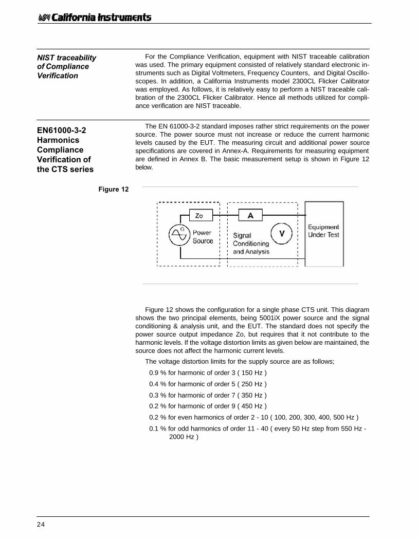
The EN 61000-3-2 standard imposes rather strict requirements on the powersource. The power source must not increase or reduce the current harmoniclevels caused by the EUT. The measuring circuit and additional power sourcespecifications are covered in Annex-A. Requirements for measuring equipmentare defined in Annex B. The basic measurement setup is shown in Figure 12below.
Figure 12 shows the configuration for a single phase CTS unit. This diagramshows the two principal elements, being 5001iX power source and the signalconditioning & analysis unit, and the EUT. The standard does not specify thepower source output impedance Zo, but requires that it not contribute to theharmonic levels. If the voltage distortion limits as given below are maintained, thesource does not affect the harmonic current levels.
The voltage distortion limits for the supply source are as follows;
0.9 % for harmonic of order 3 ( 150 Hz )
0.4 % for harmonic of order 5 ( 250 Hz )
0.3 % for harmonic of order 7 ( 350 Hz )
0.2 % for harmonic of order 9 ( 450 Hz )
0.2 % for even harmonics of order 2 - 10 ( 100, 200, 300, 400, 500 Hz )
0.1 % for odd harmonics of order 11 - 40 ( every 50 Hz step from 550 Hz -2000 Hz )
NIST traceabilityof ComplianceVerification
EN61000-3-2HarmonicsComplianceVerification ofthe CTS series
Figure 12
25
Compliance Test System Tutorial
Voltage levels are to be maintained with ± 2 %, and frequency changesmust be < ± 0.5 %
The CTS software monitors the source voltage distortion continuously, andupdates both the test data file and its display for every 320 ms or 200 ms acqui-sition window. This way, the user is absolutely assured that the test complieswith the source specification requirements as outlined in the standard. The 5001iXAC Source maintains its frequency within ± 0.05 % and the voltage level changesare < ± 0.1 %. In addition, both parameters are constantly monitored by themeasurement section and the actual levels are written to the test data file.
In the existing EN 61000-3-2 standard, the analyzer’s internal impedanceZm, is allowed to cause a voltage drop of max. 0.15 Vpk, therefore the EUTwill receive the specified voltage within very close tolerances.
The CTS series employs two active Hall effect sensors which represent NOburden at all, hence they don’t affect the measurements.
Both sensors have > 80 dB dynamic range, and one covers the low rangewhile the other covers the high range. The combined effect is a current analy-sis circuit with > 100 dB dynamic range performance. An added benefit is thatthe circuit requires no fuses as the sensors will not be damaged, even if theyare subjected to prolonged overloads of 200 Amperes. In fact, the power sourceoutput protection and mains supply circuit breakers will be triggered well be-fore any damage occurs to the current measuring circuit.
The standard calls for steady state harmonic analysis with accuracy’s bet-ter than ± 0.2 % of the rated current, or better than ± 5 % of the permissiblelimits for the specific test class.
The CTS series has a maximum harmonic analysis error ranging from± 0.1 % for the fundamental (50 Hz) to a worst case ± 4.1 % for the 40 thharmonic, fully meeting the standard. The typical performance results in errors< ± 1 mA at the 40 th harmonic. This performance is accomplished throughthe tight integration between the 5001iX power source and the signal condition-ing/analysis section. Calibration is done at the system level, and can be verifiedby the user through a NIST traceable DMM with suitable accuracy specifica-tions.
Note that harmonic analysis accuracy can be verified through various meth-ods. The CTS series utilizes Fast Fourier Transform technology to implementthe Discrete Fourier Transform as given in the standard. Sampling is suffi-ciently high to produce accurate analysis results up to 6 kHz (3 times the re-quired 2 kHz in the standard). Anti-aliasing filters are provided to filter out higherfrequencies. Given the strict sampling synchronization in the system, only rect-angular windowing with an acquisition cycle of 10 or 12 periods of the 50 Hzsignal is used (200 ms acquisition cycle) as defined as the reference method instandard.
The 1.5 second time constant filtering of the fluctuating harmonic levels usedin the CTS is in strict compliance with the requirements as given in EN 61000-4-7.
26
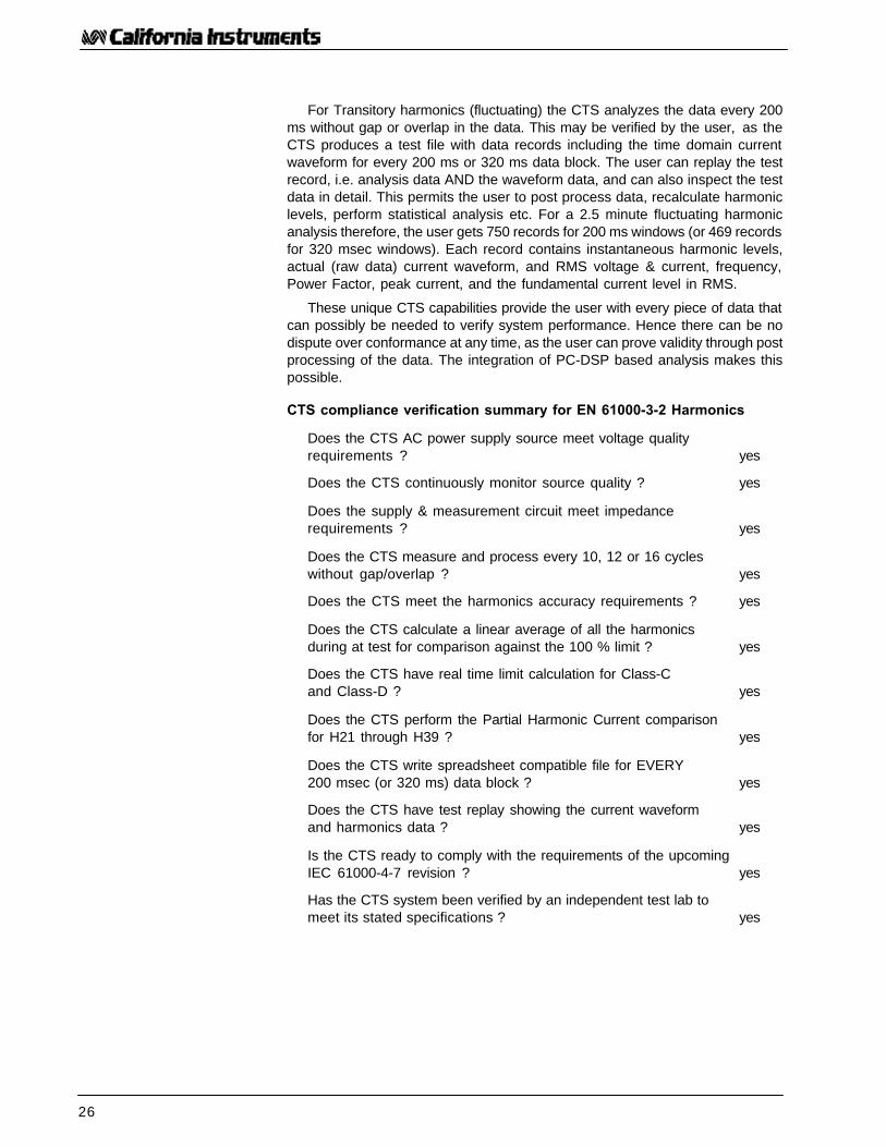
For Transitory harmonics (fluctuating) the CTS analyzes the data every 200ms without gap or overlap in the data. This may be verified by the user, as theCTS produces a test file with data records including the time domain currentwaveform for every 200 ms or 320 ms data block. The user can replay the testrecord, i.e. analysis data AND the waveform data, and can also inspect the testdata in detail. This permits the user to post process data, recalculate harmoniclevels, perform statistical analysis etc. For a 2.5 minute fluctuating harmonicanalysis therefore, the user gets 750 records for 200 ms windows (or 469 recordsfor 320 msec windows). Each record contains instantaneous harmonic levels,actual (raw data) current waveform, and RMS voltage & current, frequency,Power Factor, peak current, and the fundamental current level in RMS.
These unique CTS capabilities provide the user with every piece of data thatcan possibly be needed to verify system performance. Hence there can be nodispute over conformance at any time, as the user can prove validity through postprocessing of the data. The integration of PC-DSP based analysis makes thispossible.
CTS compliance verification summary for EN 61000-3-2 Harmonics
Does the CTS AC power supply source meet voltage qualityrequirements ? yes
Does the CTS continuously monitor source quality ? yes
Does the supply & measurement circuit meet impedancerequirements ? yes
Does the CTS measure and process every 10, 12 or 16 cycleswithout gap/overlap ? yes
Does the CTS meet the harmonics accuracy requirements ? yes
Does the CTS calculate a linear average of all the harmonicsduring at test for comparison against the 100 % limit ? yes
Does the CTS have real time limit calculation for Class-Cand Class-D ? yes
Does the CTS perform the Partial Harmonic Current comparisonfor H21 through H39 ? yes
Does the CTS write spreadsheet compatible file for EVERY200 msec (or 320 ms) data block ? yes
Does the CTS have test replay showing the current waveformand harmonics data ? yes
Is the CTS ready to comply with the requirements of the upcomingIEC 61000-4-7 revision ? yes
Has the CTS system been verified by an independent test lab tomeet its stated specifications ? yes

27
Compliance Test System Tutorial
The Flicker Meter consists of the CTS signal conditioner, AC source withbuilt-in Reference Impedance per IEC-725, combined with the DSP based mea-surement subsystem in the PC. Compliance verification can be accomplishedby modulating a resistive load, in exact accordance with the requirements asoutlined in IEC 868 - Amendment I, and as specified in EN 60868 Table-I Rect-angular Voltage modulation. The overall configuration is as given below in Fig-ure 13. The California Instruments model 2300CL Calibrator or a similar instru-ment can be used for this purpose.
Table-I of EN 60868 covers all the possible calibration points for a FlickerMeter, from 0.1 voltage change per minute to 1800 changes per minute. Bymodulating the resistive load with the required frequency (as shown in Figure13), voltage fluctuations can be created which in turn allow a Flicker Meter’sperformance to be verified for each of the calibration points. If a 60 Watt 230Vac light bulb is subjected to the same voltage fluctuations, the resulting lightFlicker would cause a short term Flicker level (Pst) of exactly 1.00, being theirritability threshold for the average human.
Voltage fluctuations must be measured every 10 ms and then the voltagechange is computed as a percentage of the nominal 230 Volt. This difference iscalled “dt” and the standard permits a maximum change of 4 %, although someproducts are permitted to have as much as 5.32 % , for a maximum duration of200 ms. If a product causes many voltage fluctuations, it will cause irritating lightFlicker. The EN 61000-3-3 standard defines a 10 minute evaluation period forPs(hort) t(erm). The voltage fluctuations are evaluated in accordance with thefiltering and Laplace Transform characteristics outlined in IEC868, and the Pstlevel cannot exceed 1.00. In addition, the standard defines a Pl(ong)t(term) to bemeasured over 2 hours. Twelve consecutive Pst readings are used to calculatePlt. Even if the product has a shorter operating cycle, the Plt calculation pro-duces a cubed average over 12 ea. Pst periods, and the non-measured periodsare “deemed to be zero” as stated in EN 61000-3-3.
The CTS series was evaluated in exact conformance with this method-ology. The selected calibration points were picked to include the mostcritical 8.77 Hz point, as well as several other frequencies that are com-monly used as checkpoints.
For the tests, the 5001iX output impedance is programmed to the requiredFlicker impedance. This effectively inserts the IEC-725 compliant Reference Im-pedance in the circuit as shown above in Figure 13. The (non-inductive) resis-tive load is modulated at the appropriate frequencies, and at an exactly definedlevel. Note that voltage and current levels, as well as the frequency and modu-lation duty cycle can all be verified with NIST traceable instruments.
EN61000-3-3Flicker complianceVerification of theCTS series
Figure 13EN 60868 Table I
CPM Mod F (Hz) % Mod
0.10 0.0008 7.3910.20 0.0017 4.5840.30 0.0025 3.8420.40 0.0033 3.5400.50 0.0042 3.3500.60 0.0050 3.1690.76 0.0063 2.9790.84 0.0070 2.8670.95 0.0079 2.7651.06 0.0088 2.6791.20 0.0100 2.5791.36 0.0113 2.4841.55 0.0129 2.3491.78 0.0148 2.2942.05 0.0171 2.1932.39 0.0199 2.0912.79 0.0233 1.9893.29 0.0274 1.8933.92 0.0327 1.7894.71 0.0393 1.6795.72 0.0477 1.5717.04 0.0587 1.4568.79 0.0733 1.348
11.16 0.0930 1.24414.44 0.1203 1.15019.10 0.1592 1.06226.60 0.2217 0.97532.00 0.2667 0.94239.00 0.3250 0.90648.70 0.4058 0.86661.80 0.5150 0.84280.50 0.6708 0.782
110.00 0.9167 0.725175.00 1.4600 0.635275.00 2.2900 0.551380.00 3.1700 0.500475.00 3.9600 0.476580.00 4.8300 0.423690.00 5.7500 0.367795.00 6.6300 0.321
1052 8.77 0.2761180 9.83 0.2831400 11.67 0.3311620 13.50 0.4021800 15.00 0.480

28
The standard states that overall accuracy must be better than ± 8 %, whichincludes any inaccuracies in the IEC-725 Reference Impedance, as well as mea-surement errors. As follows from the table below, the CTS accuracy is well withinthe required tolerance levels.
Modulation Modulation Programmed Measured ErrorLevel in % Frequency Pst level Pst level Percentage
(must be < 8 %)1.00 % ~ 0.16 Hz ~ 0.94 0.955 + 1.6 %0.50 % 0.916 Hz 0.69 0.690 + 0.0 %0.50 % 3.960 Hz 1.05 1.054 + 0.4 %0.25 % 8.767 Hz 0.91 0.920 + 1.1 %0.25 % 13.50 Hz 0.62 0.640 + 3.2 %
Notes: The 0.16 Hz modulation was controlled manually.Nominal voltage for all tests: 230 Vac - 50 Hz.
Because of the tight integration of the CTS DSP based acquisition insidethe PC, the RMS voltage for every 10 ms sample period is written to a test file,along with all the calculated Flicker parameters which are derived from these10 ms. measurements. The file has 100 ea. RMS levels (1 sec.) per line, inspreadsheet compatible format. This unique capability allows the user to postprocess all data, and verify exact compliance to the standard.
The standard also requires that the system measure steady state RMSlevels (called dc) and the maximum voltage deviation (dmax) in a specificway. The CTS series follows these requirements and, in addition, has aunique real time display of these parameters, as well as for Ut, the instan-taneous RMS voltage level for each 10 ms measurement period.
The integration of PC/DSP based analysis of the CTS series makes theseunique capabilities possible.
CTS compliance verification summary for EN 61000-3-3 Flicker Analysis
Does the CTS supply source meet the low output impedancespecification ? yes
Does the CTS Programmable Reference Impedance meet theIEC-725 requirement ? yes
Does the CTS implement the Flicker Meter in accordance withIEC-868 ? yes
Does the CTS measure and process data every 10 ms.without gaps ? yes
Does the CTS meet the overall accuracy requirement of ± 8 % ? yes
Does the CTS produce test reports with Pst & Plt graphs ? yes
Does the CTS write spreadsheet compatible data files forALL 10 ms measurements ? yes
Does the CTS have real time display of voltage variations(dc - dt - Ut)? yes
Can the user reproduce all Flicker calculations using thetest files ? yes
Test results 5001iX-CTS system perIEC868 Amendm. I
Table 4

29
Compliance Test System Tutorial
Both Harmonics and Flicker tests require the AC source to meet specificoutput characteristics. California Instruments has gone through great lengths indeveloping the iX series of AC/DC power sources used in the CTS system toensure these requirements were met. This section contains actual voltage dis-tortion data taken on a production model 5001iX while driving a high crestfactor load. This load actually exceeds the IEC harmonics Class A limits andas such represents a worst case situation for the AC source. The AC sourceshould be able to drive a load that produces current harmonics at the maxi-mum class limit levels and still have less than the maximum allowable voltagedistortion. This requires that the AC source has a low source impedance. Anycurrent harmonic will produce voltage drop across the source impedance whichcontributes to the voltage distortion. The lower the source impedance, the lowerthe contribution to the voltage distortion.
Even Limit Odd LimitHarm (% of Vrms) Harm (% of Vrms)
2 0.2 % 3 0.9 %4 0.2 % 5 0.4 %6 0.2 % 7 0.3 %8 0.2 % 9 0.2 %10 0.2 % 11 - 39 0.1 %
12 - 40 0.1 %
Maximum voltage distortion limits for AC source qualification are expressedin a percentage of the fundamental voltage amplitude for the first 40 voltageharmonics. If this maximum distortion level is exceeded at any time during thetest, the test data becomes invalid. The specific harmonic voltage limits setforth by the EN 61000-3-2 standard are listed in Table 5. The total harmonicdistortion (THD) of this waveform equals only 1.2 %.
Testing an AC source for voltage distortion under the EN 61000-3-2 worstcase conditions requires the use of a complex load that produces current har-monics close to or equal to the maximum harmonic current limits allowed un-der the standard. Since the maximum load specified under the standard draws16 Amps rms of fundamental current, the load must be rated for this current. Asample load that generates a current harmonic pattern close to the EN 61000-3-2 standard is shown in Figure 14. This type of load simulates conditions of aload that would still pass the requirement.
AC SourceCompliance
Voltage distortionlimits
Checking ACSource Distortion
Table 5

30
With the load connected, harmonic distortion measurements must be made.Since it is unlikely that each individual current harmonic of the load is exactly atthe standard’s limit, some interpolation may be required, i.e. ratio the voltagedistortion up or down, assuming simple ohms law applied to the current, and afixed output impedance over the small range considered.
The California Instruments’ iX Series of programmable AC sources is a familyof high power, low distortion units offering very low dynamic output impedance.This makes them ideally suited for EN 61000-3-2 testing. The test data shown inTable 6 shows the actual voltage harmonics with the load depicted in Figure 14connected. As some of the current harmonics exceed the EN 61000-3-2 stan-dard limits, some interpolation is used. The load current values for each harmonicare shown in column 2. Column 3 shows the EN 61000-3-2 specification currentlimits. While this load would fail the test, it provides a good load for voltagedistortion testing of the source as it is close to or over the limit on most harmon-ics. The actual voltage distortion of the AC source is shown in column four. Theallowable limits are shown in column 5. If we interpolate these values for thedifference between actual current harmonics and specification limits (column 6),the AC source easily meets the source requirements.
From this data it is clear that the iX Series exceeds the source requirementsfor the EN 61000-3-2 standard. For EN 61000-3-3 (Flicker) testing, the samesource can be used as it offers a programmable output impedance.
The California Instruments Compliance Test Systems (CTS) use the iX Se-ries AC sources and offer both EN 61000-3-2 and EN 61000-3-3 source andmeasurements for either single or three phase applications.
Before selecting an AC source or IEC test system for IEC testing, be sure toverify compliance of the AC source to the source requirement portion of the EN61000-3-2 standard.
Test Data for iXSeries AC Sources
Conclusion
Figure 14

31
Compliance Test System Tutorial
n Load Current Voltage Distortion InterpolatedDistortion
1 2 3 4 5 6Harm. Actual Spec Actual Spec Limit D%=
(IA) Lim (IL) (A%) A%*(IL/IA)2 1.853 1.62 0.078 0.200 0.0683 3.837 3.45 0.380 0.900 0.3424 1.139 0.65 0.072 0.200 0.0415 2.226 1.71 0.130 0.400 0.1006 0.463 0.45 0.057 0.200 0.0557 1.073 1.16 0.112 0.300 0.1218 0.126 0.35 0.019 0.200 0.0539 0.700 0.60 0.065 0.200 0.05610 0.190 0.28 0.096 0.200 0.14111 0.718 0.50 0.089 0.100 0.06212 0.254 0.23 0.050 0.100 0.04513 0.605 0.31 0.083 0.100 0.04314 0.252 0.20 0.037 0.100 0.02915 0.418 0.23 0.083 0.100 0.04616 0.173 0.18 0.020 0.100 0.02117 0.371 0.20 0.093 0.100 0.05018 0.104 0.16 0.040 0.100 0.06219 0.357 0.18 0.082 0.100 0.04120 0.104 0.14 0.026 0.100 0.03521 0.279 0.16 0.074 0.100 0.04222 0.119 0.13 0.041 0.100 0.04523 0.228 0.15 0.066 0.100 0.04324 0.119 0.12 0.034 0.100 0.03425 0.209 0.14 0.069 0.100 0.04626 0.098 0.10 0.032 0.100 0.03327 0.165 0.13 0.072 0.100 0.05728 0.063 0.10 0.035 0.100 0.05629 0.105 0.12 0.055 0.100 0.06330 0.058 0.09 0.027 0.100 0.04231 0.069 0.11 0.024 0.100 0.03832 0.057 0.09 0.025 0.100 0.03933 0.054 0.11 0.023 0.100 0.04734 0.043 0.08 0.027 0.100 0.05035 0.041 0.10 0.009 0.100 0.02236 0.030 0.08 0.017 0.100 0.04537 0.040 0.09 0.028 0.100 0.06338 0.013 0.07 0.008 0.100 0.04339 0.052 0.09 0.021 0.100 0.03640 0.014 0.07 0.016 0.100 0.080
iX Series AC source voltage harmonics under worst case EN61000-3-2 load
Test Data for iXSeries AC Sources
Table 6

32
Appendix B: High Power Compliance Test
Within the European Community (EC) there is a strong desire for standardsthat cover products up to 75 Amp/phase. Such standards permit manufacturersto follow the “standards route” to product certification, which is the lowest costmethod to certification and (conditional) connection to the public supply system,without having to overcome major obstacles. Whereas TC77-SC77A/WG1managed to produce a first CD (committee draft) for the harmonics standardIEC 61000-3-12, the next CD and the FDIS are not expected till late 2001.Working Group 2 (TC77/SC77A/WG2) on the other hand progressed faster,and IEC 61000-3-11 for Flicker tests up to 75 Amp per phase was published inAugust 2000. Even though the final version of the IEC 61000-3-12 harmonicsstandard up to 75 Amp per phase is yet to be generated, there is enough infor-mation at this time to consider its impact on a compliance test system.
The key requirements of IEC 61000-3-11 are as follows;
If equipment complies with the requirements of IEC 61000-3-3, it is not sub-ject to conditional connection, and this may be declared by the manufacturer.Equipment which does NOT meet IEC 61000-3-3 when tested with the stan-dard Reference Impedance is subject to conditional connection, and the manu-facturer must either;
a) Determine the maximum system impedance Z max at which the equip-ment will still meet the Flicker limits given in IEC 61000-3-3, and declarethis, and instruct the user to determine that the system impedance atthe equipment connection point is less than this Z max . This may haveto be done in consultation with the supply authority.
b) Test the equipment in accordance with section 6.3 of the standard, anddeclare in the equipment manual that this equipment is for use in pre-mises having > 100 Amp per phase capability. This also must be de-clared on the equipment itself. The manual must also instruct the userto determine, in consultation with the supply authority if necessary, thatthe supply capacity is sufficient. As will follow from the foregoing discus-sion regarding IEC 61000-3-3, the voltage drop that is caused by elec-trical equipment depends on the current level AND on the system im-pedance. In the case of Flicker testing, the system impedance is fixedat the IEC 60725 Reference Impedance values. In networks for highercurrent equipment, the system impedance is typically less than the Ref-erence. Impedance values. Thus, it stands to reason that a manufacturercan test the equipment with such lower impedance levels, and IEC 61000-3-11 includes specific formulas to convert the obtained dc, dmax, Pst,and Plt readings from the observed test level to the values that wouldhave been obtained, had the standard Ref. Impedance been used.
Introduction
Flicker testing perIEC 61000-3-11

33
Compliance Test System Tutorial
The formulas are all straight linear conversions, where the ratio between Zref /Z test is determined, and then used to multiply with the measured dc, dmax,Pst, and Plt values. In other words, assume the test impedance is 0.25 Ohmresistive and 0.25 Ohm inductive ( the Z test values given in section 6.3 of61000-3-11). In this case the ratio between Z ref and Z test is 1.33. Thus themeasured dc level (etc. ) is multiplied by 1.33 to obtain the dc level that wouldhave been measured had a Reference Impedance been used. If the so translatedparameter levels meet the limits of IEC 61000-3-3, the values for Z test could bedeclared. The advantage of having a lower test impedance is rather straight for-ward. Consider that a product that requires 75 Amp per phase will dissipate 75 x75 x 0.4 = 2250 Watt in just the resistive portion of the Ref. Impedance. Thistranslates to at least 3 x 2250 = 6.75 KW for a 3 phase Ref. Imp. unit, which isexpensive to build. Reducing this to about half the size still requires a heftycooling capability, but this is significantly easier to achieve at ~ 4 KW than at ~7 KW.
Note that the testing authority may use impedance levels that are lower thanthose given in section 6.3 of the standard. The impedance value of Z test mustbe selected such that the inductive component is between 0.5 - 0.75 times theresistive part. Also, it is recommended to select the impedance value such thatthe nominal voltage drop due to the equipment current is between 3 - 5 % of thetest voltage. The IEC 61000-3-3 standard also provides an evaluation proce-dure, which permits the user to determine the maximum permissible imped-ance at which the equipment can be connected. This procedure must be usedwhen the equipment fails the requirements of IEC 61000-3-3. The evaluationprocedure includes formulas to determine four system impedance values;
Zsys1 = Zref x d max limit/d max Ref with d max Ref being the dmaxvalue that is obtained if Zref is used.
Of course this d max Re value can be obtained using the conversion formulagiven on the previous page.
Zsys2 = Zref x 3.3/dc Ref with dc Ref being the value that is obtained ifZref is used.
Zsys3 = Zref x [ 1/Pst ref ] 3/2 with Pst ref being the value that is ob-tained if Zref is used.
Zsys4 = Zref x [ 1/Plt ref ] 3/2 with Plt ref being the value that is obtainedif Zref is used.
The lowest of the four calculated impedances is the value that the manufac-turer must declare as the maximum permissible system impedance at the pointwhere the equipment is to be connected. If the manufacturer wants to use methodb; i.e. declare that the supply capacity must be at least 100 Amp, the standardcalls for a test that utilizes specific Z test values. These values are given inFigure 15.
Figure 15

34
The most important aspect of IEC 61000-3-12 is that the AC power sourcemust have a low output impedance and drive > 150 Amp peak, so that the har-monics emissions are not affected. Even though the exact current harmonicslimits are still being debated, fact is that IEC 61000-3-12 will have proportionallimits; i.e, limits that depend on the product’s power or fundamental current level.Thus the analysis system must measure both if it is to be expected that the usercan later implement the limits for the test classes. Provided the measurementsystem can handle the 75 Amp rms (up to at least 150 Amp peak) the systemcould possibly be configured to perform analysis per IEC 61000-3-12. It must beassumed that the requirements given in IEC 61000-4-7 will apply to the measure-ment requirements for 61000-3-12, similar to the amendment of IEC 61000-3-2,and in fact the existing 61000-3-12 CD references IEC 61000-4-7. Thus, if themeasurement system and the power source capability conform to these condi-tions, the software could in the future be configured to handle the limit compari-son. The test setup is very similar to the requirements for IEC 61000-3-2.. Thus,the primary difference for both < 75 Amp Flicker and harmonics standards is thedemand to generate clean power up to 75 Amp, and accurately measure andanalyze these high power levels.
California Instruments is developing solutions for higher power IEC compli-ance testing that will leverage the technology used in today’s CTS series sys-tems. This will provide a smooth upgrade path for users of existing CTS sys-tems that are faced with increasing demands for test capability. Contact theCalifornia Instruments sales department at [email protected] for informationon high power IEC test solutions.
Harmonics testingper IEC 61000-3-12
High PowerSolutions

35
Compliance Test System Tutorial

36
Contact California Instruments:TEL: 858 677-9040FAX: 858 677-0940
Email: [email protected] page: http://www.calinst.com
9689 Towne Centre Drive, San Diego, CA 92121-1964 (858) 677-9040 FAX : (858) 677-0940© Copyright 1998-2001, California Instruments Corp. Specifications subject to change without notice Printed in the USA. APN119B 11/01