appendix a – report formats - north carolina management/dwm/ust/nonust/nurp_appx... · 4. initial...
TRANSCRIPT

56
Appendices Appendix A Report Formats ................................................................................................................................... 57
1. Notification of Discharge Report ........................................................................................................................ 60 2. Free Product Recovery Report ............................................................................................................................ 62 3. Free Product Recovery System Specification Report ......................................................................................... 65 4. Initial Site Assessment Report ............................................................................................................................ 71 5. Comprehensive Site Assessment Report ............................................................................................................ 77 6. Corrective Action Plan ....................................................................................................................................... 85 7. Monitoring Reports ............................................................................................................................................. 92 8. System Enhancement Recommendation Report ................................................................................................. 99 9. New Technology Cleanup Plan ........................................................................................................................ 102 10. Site Closure Report ......................................................................................................................................... 108 11. Receptor Survey ............................................................................................................................................. 115 12. Format of Individual Public Notice for Non-UST Releases of Petroleum...................................................... 116 13. VPH (Aliphatics/Aromatics) Laboratory Reporting Form ............................................................................. 118 14. EPH (Aliphatics/Aromatics) Laboratory Reporting Form .............................................................................. 120
Appendix B Reporting Tables ............................................................................................................................... 122 Table B-1: Site History – UST/AST System and Other Release Information ....................................................... 123 Table B-2: Site History - UST/AST Owner/Operator and Other Responsible Party Information ......................... 124 Table B-3: Summary of Soil Sampling Results ..................................................................................................... 125 Table B-4: Summary of Groundwater and Surface Water Sampling Results ........................................................ 126 Table B-5: Public and Private Water Supply Well and Other Receptor Information ............................................ 127 Table B-6: Property Owners/ Occupants ............................................................................................................... 128 Table B-7: Monitoring and Remediation Well Construction Information ............................................................. 129 Table B-8A: Free Product Recovery Information.................................................................................................. 130 Table B-8B: Cumulative Volume of Free Product Recovered from Site .............................................................. 130 Table B-9: Current and Historical Groundwater Elevations and Free Product Thickness ..................................... 131 Table B-10: Land Use ............................................................................................................................................ 132
Appendix C Required Permits ............................................................................................................................... 133 Appendix D Aquifer Testing .................................................................................................................................. 137
1. Slug Tests ......................................................................................................................................................... 137 2. Pump Tests ....................................................................................................................................................... 138
Appendix E Development of Maximum Soil Contaminant Concentrations ....................................................... 139 Appendix F Guidance Pertaining to Releases from Contaminant Sources Other than Non-UST Petroleum Releases ..................................................................................................................................................................... 141

Appendix A Report Formats Non-UST Releases of Petroleum
57 Change 1
Appendix A Report Formats
The initial response and abatement, assessment, and remediation of a site with groundwater and/or soil contamination should be documented by following the reporting requirements presented in Appendix A. Unless otherwise indicated, these reporting requirements apply to all non-UST petroleum releases. Reports must be submitted in the format specified in Appendix A, or they will not be approved. The regional office may deny approval of a report if any of the elements of the report format specified in Appendix A have not been included or have not been sufficiently addressed. The regional office may require that additional information be submitted to support a report. A report will not be approved until it is submitted in a complete form. The report formats are listed below and presented in the following pages of Appendix A in the order in which they usually are required 1. Notification of Discharge Report: This report notifies the Department of a non-UST petroleum release. A
responsible party must submit the information required for the Notification of Discharge Report to the appropriate UST Section regional office of the Department by telephone, fax, electronic mail, or other means within 24 hours of discovery of a release. The information required for either a verbal or written Notification of Discharge Report is specified on the 24-Hour Notification of Discharge Form (UST Form 62). Using the verbal or written report submitted by responsible party (and other sources of information), the regional office will complete the 24-Hour Notification of Discharge Form (UST Form 62).
2. Free Product Recovery Report: This report presents information on free product recovery activities following
the initial and any subsequent recovery event whenever the timing is appropriate. This report should be prepared and submitted only when reporting of free product recovery cannot not be achieved within a reasonable time period by incorporation in the Initial Assessment Report, the Comprehensive Site Assessment Report, the Corrective Action Plan, or routine Monitoring Reports. A separate Free Product Recovery Report is required only when a more comprehensive report is not due simultaneously.
3. Free Product Recovery System Specification Report: Following the initial free product recovery event and
report (a Free Product Recovery Report or, if the timing is appropriate, an Initial Assessment Report, Comprehensive Site Assessment Report, or pre-CAP Monitoring Report) the responsible party must investigate to determine the product type, thickness, rate of recovery, and lateral extent of free product; relevant hydrogeological factors; and potential receptors and then must submit the results of this investigation to the appropriate regional office of the UST Section in a FP Recovery System Specification Report. This report should evaluate the results of the investigation and possible active free product recovery system options (e.g., excavation, SVE, MMPE, AFVR); propose a recovery plan which incorporates the most appropriate recovery system option; and conclude with a schedule for the recovery plan (Eventually, this recovery plan will be superceded by any recovery plan incorporated in the Corrective Action Plan.)
4. Initial Site Assessment Report: The Initial Assessment Report documents site history and characterization,
free product investigation and removal (if applicable), groundwater and surface water investigation (if applicable), initial response and abatement actions, and the excavation of contaminated soil, with the results of post-excavation confirmatory soil sampling. This report should be completed and submitted to the appropriate regional office within 30 days of the discovery of a release.
5. Comprehensive Site Assessment Report: The Comprehensive Site Assessment (CSA) Report
documents investigation activities performed to characterize the cause, significance, and extent of contamination from a release from a UST system. The CSA Report should be completed and submitted to the Division of Waste Management regional office within 90 Days of the date of a Notice of Regulatory Requirements (NORR) requiring the report. The CSA will not be approved until it is submitted in a complete form.
6. Corrective Action Plan: The Corrective Action Plan (CAP) proposes and evaluates actions to cleanup
contamination caused by a release from a UST system. The CAP addresses both soil and groundwater contamination. For releases involving only soil contamination, only the sections of the CAP format that address soil contamination should be included. The CAP should be completed and submitted to the Division of Waste Management regional office within 60 Days of the date of a Notice of Regulatory Requirements (NORR) requiring the report. The CAP will not be approved until it is submitted in a complete form. The responsible party must receive approval of a CAP before the CAP is implemented.

Appendix A Report Formats Non-UST Releases of Petroleum
58 Change 1
7. Monitoring Reports: Monitoring Reports document the periodic monitoring of groundwater and soil in order to evaluate changes in contaminant concentration over time at specific locations. The information presented in a series of Monitoring Reports is used to monitor plume migration, evaluate the effectiveness of corrective action, account for the effects of fluctuating water table elevation versus contaminant concentrations, etc. Submittal of periodic Monitoring Reports may be requested by the appropriate regional office or, if applicable, may be required as part of an approved Corrective Action Plan. There are two types of Monitoring Report:
Pre-CAP Monitoring Report: Pre-CAP monitoring should be conducted if required by the appropriate regional
office. Pre-CAP monitoring primarily involves sampling monitoring wells at the site before developing a CAP. The Pre-CAP Monitoring Report describes the monitoring event and presents and evaluates the analytical results. The Pre-CAP Monitoring Report should be submitted semi-annually, unless the regional office indicates a different schedule, by the end of the month subsequent to that of the monitoring event.
CAP Monitoring Report: CAP monitoring should be conducted only after the CAP has been approved. The primary functions of CAP monitoring are to monitor the progress of an active remediation system or remediation by natural attenuation in achievement of cleanup goals and to verify that cleanup levels have been achieved. The CAP Monitoring Report describes the monitoring event and presents and evaluates the analytical results. The report also presents a calculation of the percentage of the contaminant reduction achieved at the site at the time of the monitoring event, and it compares the percentage of contaminant reduction achieved to that proposed as the cleanup milestone for this time period in the CAP. (The regional office must approve the selection of key monitoring wells and contaminants of concern for use in this calculation.) If a combination of active treatment and remediation by natural attenuation is being used to remediate contamination, monitoring results should be submitted in one report of this type. The CAP Monitoring Reports should be submitted semi-annually, unless the regional office indicates a different schedule, by the end of the month subsequent to that of the monitoring event.
8. System Enhancement Recommendation Report. This report is used, when directed by Department, to
propose a material change or major enhancement to an existing remediation system. 9. New Technology Cleanup Plan. This report is used when an existing remediation system is determined to be
effective no longer, to propose replacement by a new technology or addition of a new technology. 10. Site Closure Report: The Site Closure Report documents remediation of contaminated soil and groundwater to
the cleanup goals. The Site Closure Report also incorporates a request for the Department to issue a notice of no further action. For releases where groundwater does not require remediation, only those reporting requirements related to soil cleanup are applicable. The Site Closure Report will not be approved until it is submitted in a complete form.
NOTE: A Licensed Geologist and/or Professional Engineer Certification is required for all reports following the 24
Hour Notification of Discharge Report, except for specifically-approved reports of analytical data where no hydrogeological evaluations, interpretations or recommendations are made. CSA reports, groundwater monitoring reports, and CAPs that do not contain plans or designs for active groundwater remediation systems may be prepared and sealed by either a North Carolina Professional Engineer or Licensed Geologist. For the purpose of clarifying certification requirements, active groundwater remediation is defined to mean any remediation method that employs the use of pumps to move liquids and/or gases at a site. All plans and specifications intended for use in construction of or for obtaining regulatory authorization to construct an active remediation system must be prepared under responsible charge of a Professional Engineer and must bear the seal of the same. The applicable report must display the seal and signature of the certifying P.E. or L.G. and the name and certification number of the company or corporation on the title page [see 15A NCAC 2L .0103(e)].
10. Receptor Survey 11. Format of Individual Public Notice for Non-Petroleum UST Releases (15A NCAC 2L .0114(b)) 12. VPH (Aliphatics/Aromatics) Laboratory Reporting Form 13. EPH (Aliphatics/Aromatics) Laboratory Reporting Form

Appendix A Report Formats Non-UST Releases of Petroleum
59 Change 1
Notification of Discharge Report Appendix A Report Formats
60 Change 1
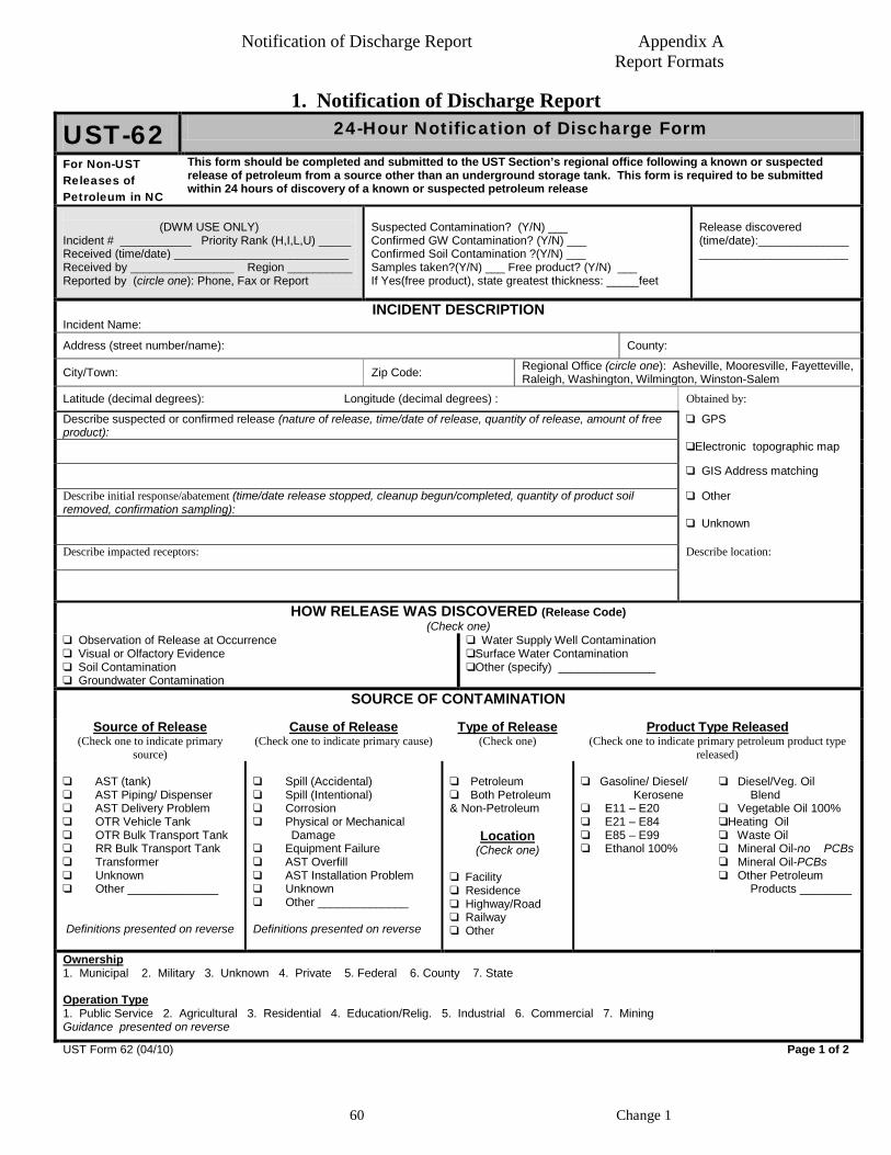
1. Notification of Discharge Report
UST-62 24-Hour Notification of Discharge Form
For Non-UST Releases of Petroleum in NC
This form should be completed and submitted to the UST Section’s regional office following a known or suspected release of petroleum from a source other than an underground storage tank. This form is required to be submitted within 24 hours of discovery of a known or suspected petroleum release
(DWM USE ONLY)
Incident # ___________ Priority Rank (H,I,L,U) _____ Received (time/date) ___________________________ Received by ________________ Region __________ Reported by (circle one): Phone, Fax or Report
Suspected Contamination? (Y/N) ___ Confirmed GW Contamination? (Y/N) ___ Confirmed Soil Contamination ?(Y/N) ___ Samples taken?(Y/N) ___ Free product? (Y/N) ___ If Yes(free product), state greatest thickness: _____feet
Release discovered (time/date):_____________________________________
INCIDENT DESCRIPTION Incident Name:
Address (street number/name): County:
City/Town: Zip Code: Regional Office (circle one): Asheville, Mooresville, Fayetteville, Raleigh, Washington, Wilmington, Winston-Salem
Latitude (decimal degrees): Longitude (decimal degrees) : Obtained by:
Describe suspected or confirmed release (nature of release, time/date of release, quantity of release, amount of free product):
GPS
Electronic topographic map
GIS Address matching
Describe initial response/abatement (time/date release stopped, cleanup begun/completed, quantity of product soil removed, confirmation sampling):
Other
Unknown
Describe impacted receptors: Describe location:
HOW RELEASE WAS DISCOVERED (Release Code) (Check one)
Observation of Release at Occurrence Visual or Olfactory Evidence Soil Contamination Groundwater Contamination
Water Supply Well Contamination Surface Water Contamination Other (specify) _______________
SOURCE OF CONTAMINATION
Source of Release (Check one to indicate primary
source)
Cause of Release (Check one to indicate primary cause)
Type of Release (Check one)
Product Type Released (Check one to indicate primary petroleum product type
released) AST (tank) AST Piping/ Dispenser AST Delivery Problem OTR Vehicle Tank OTR Bulk Transport Tank RR Bulk Transport Tank Transformer Unknown Other ______________
Definitions presented on reverse
Spill (Accidental) Spill (Intentional) Corrosion Physical or Mechanical
Damage Equipment Failure AST Overfill AST Installation Problem Unknown Other ______________ Definitions presented on reverse
Petroleum Both Petroleum & Non-Petroleum
Location (Check one)
Facility Residence Highway/Road Railway Other
Gasoline/ Diesel/ Kerosene E11 – E20 E21 – E84 E85 – E99 Ethanol 100%
Diesel/Veg. Oil Blend Vegetable Oil 100% Heating Oil Waste Oil Mineral Oil-no PCBs Mineral Oil-PCBs Other Petroleum Products ________
Ownership 1. Municipal 2. Military 3. Unknown 4. Private 5. Federal 6. County 7. State Operation Type 1. Public Service 2. Agricultural 3. Residential 4. Education/Relig. 5. Industrial 6. Commercial 7. Mining Guidance presented on reverse UST Form 62 (04/10) Page 1 of 2

Notification of Discharge Report Appendix A Report Formats
61 Change 1
IMPACT ON DRINKING WATER SUPPLIES
Water Supply Wells Affected? 1. Yes 2. No 3. Unknown Number of Water Supply Wells Affected ______
List of Water Supply Wells Contaminated: (Include Users Names, Addresses and Phone Numbers. Attach additional sheet if necessary) 1. 2. 3.
PARTY RESPONSIBLE FOR RELEASE (if the source of the release is not an AST system or if it is an AST system and there is a responsible party other than the AST system owner/ operator) Name of Person/Company Address
City State Zip Code Telephone Number
AST SYSTEM OWNER(if the source of the release is an AST system) AST Owner/Company Address
City State Zip Code Telephone Number
AST SYSTEM OPERATOR(if the source of the release is an AST system)
UST Operator/Company Address
City State Zip Code Telephone Number
LANDOWNER AT LOCATION OF INCIDENT Landowner Address
City State Zip Code Telephone Number
Draw Sketch of Area or Provide Map(showing incident site, location of release, two major road intersections, potential receptors) Attach sketch or map to form.
Give Directions to Incident Site Attach directions to form if necessary.
Person Reporting Incident Company Telephone Number Title Address Date
UST Form 62 (04/10) Page 2 of 2 Definitions of Sources AST (Tank): means the tank is used to store product AST Piping: means the piping and connectors running from the tank to the dispenser or other end-use equipment AST Dispenser: includes the dispenser and the equipment used to connect the dispenser to the piping AST Delivery Problem: identifies releases that occurred during product delivery to the tank. OTR Vehicle Tank: means the tank is used to store product to fuel an over the road vehicle OTR Bulk Transport Tank: means a tank that is used to transport product in bulk over the road (by truck) RR :bulk Transport Tank: means a tank that is used to transport product in bulk by train Transformer: means electrical transformer Other: serves as the option to use when the release source is known but does not fit into one of the preceding categories Unknown: identifies releases for which the source has not been determined Definitions of Causes Spill (Accidental): use this cause when a spill occurs accidentally(e.g., when the delivery hose is disconnected from a fill pipe) Spill (Intentional): use this cause when a spill occurs intentionally (e.g., intentional dumping or breakage) Corrosion: use when a metal tank, piping, or other component has a release due to corrosion Physical or Mechanical Damage: use for all types of physical or mechanical damage, except corrosion Equipment failure: use when a release occurs due to equipment failure other than corrosion or physical or mechanical damage AST Overfill: use when an overfill occurs (e.g., overfills may occur from the fill pipe at the tank or when the nozzle fails to shut off at the dispenser) AST Installation Problem: use when the problem is determined to have occurred specifically because the AST system was not installed properly Other: use this option when the cause is known but does not fit into one of the preceding categories Unknown: use when the cause has not been determined Guidance: Ownership and Operator Type Ownership select the category which describes owner of the AST system, bulk transport tank, or other release source Operator Type select the category which describes the operation in which owner uses the AST system, bulk transport tank, or other release source

Free Product Recovery Report Appendix A Report Formats
62
2. Free Product Recovery Report Minimum elements of the report: A. Site Information
1. Site Identification Date of Report: ___________ Facility I.D.: _____________Incident Number: ______________Site Risk/Non-UST Rank: _________ Site Name: ___________________________________________________________________________ Site Street Address: ____________________________________________________________________ City/Town: ________________________Zip Code: ________County: ___________________________ Description of Geographical Data Point (e.g., dispenser): __________________________________ Location Method (GPS, topographical map, other):___________________________________________ Latitude (decimal degrees): ____________________ Longitude (decimal degrees): _________________
2. Information about Contacts Associated with the Release (Addresses must include street, city, state, zip code
and mailing address, if different) UST/AST Owner: _____________________________________________________________________
Address: __________________________________________________Tel: _______________________ UST/AST Operator: ___________________________________________________________________
Address: __________________________________________________Tel: _______________________ Other Person Associated with Release: _____________________________________________________
Address: __________________________________________________Tel: _______________________ Property Owner: ______________________________________________________________________
Address: __________________________________________________Tel: _______________________ Property Occupant: ____________________________________________________________________
Address: __________________________________________________Tel: _______________________ Consultant/Contractor: _________________________________________________________________
Address: __________________________________________________Tel: _______________________ Analytical Laboratory: _______________________________________State Certification No.________
Address: __________________________________________________Tel: _______________________
3. Information about Release Date Discovered: _____________________________________________________________________ Estimated Quantity of Release: __________________________________________________________ Cause of Release: _____________________________________________________________________ Source of Release: ____________________________________________________________________ Sizes and Contents of Tank or Other Containment from which the Release Occurred:________________
4. Certification (The title page must display the seal and signature of the certifying P.E. or L.G. and the name and certification number of the company or corporation [See 15A NCAC 2L .0103(e).])
I, _____________________________, a Professional Engineer/Licensed Geologist (circle one) for (firm or company of employment), do certify that the information contained in this report is correct and accurate to the best of my knowledge. (Please Affix Seal and Signature) __________________(Name of company or corporation) is licensed to practice geology/engineering (circle one or both) in North Carolina. The certification number of the company or corporation is __________________.

Free Product Recovery Report Appendix A Report Formats
63
B. Site Status and Conclusions Discuss the status of free product at the site, as follows: 1. If free product is, or has been, present at the site, describe its current and historical status (product distribution,
thickness, recovery activities). For an initial report, provide the results of a free product evaluation based on bail-down test(s) at the most highly impacted location(s), to include free product thickness and recovery rate. Refer to tables (from Guidelines, Appendix B)in Section D: Table B-7, Monitoring and Remediation Well Construction Information; and Table B-8A, Free Product Recovery Information; Table B-8B, Cumulative Volume of Free Product Recovered from Site; and Table B-9, Current and Historical Groundwater Elevations and Free Product Thickness. Also refer to map(s) showing extent of free product in Section C.
2. Identify any on-site or off-site effluent discharges, treatment used, effluent quality, permitting actions taken, and location of such discharges and identify the disposition of recovered free product ( refer to attached product disposal manifests).
3. Document the performance, total cost, and cost per gallon to date of each method of free product recovery used at site. Justify why the technology is or was used.
4. Provide conclusions and recommendations concerning historical, current, and future recovery activities, including: Any proposal to change the current method of free product recovery to a better or more cost-effective
technology; .Any determination that free product has been eliminated from the site with a recommendation to reclassify
the risk posed by the release, if applicable. C. Figures
Provide the following: 1. A topographic map illustrating the area within 1500-foot radius of the source of the release, showing: Topographic contours; Site location; Buildings; Adjacent streets, roads, highways (identified by street names and numbers); Surface water bodies; Groundwater flow direction (if determined); and North arrow and scale.
2. A site map* and cross-sections illustrating the release site (AST system(s), UST system(s), location of spill, etc.) drawn to scale, showing: Buildings and property boundaries; Underground utilities, such as sewer lines and other conduits; basements; and vaults; Water supply wells, surface water bodies Location and orientation of current and former ASTs, UST(s), pumps; product lines, sumps, etc.; Length, diameter and volume of current and former ASTs and UST(s); Type of material(s) (currently and formerly) in AST(s) and UST(s) or spilled; Groundwater monitoring locations, if applicable; Groundwater flow direction, if determined; and North arrow and scale.
3. Provide a free product map* showing thickness (in feet) and extent of free product using contour lines. 4. Provide a potential receptor map that clearly identifies water supply wells (municipal or public/private wells,
etc.) and other potential receptors (surface water bodies, basements, utilities, WHP areas, etc.) which are at risk. *Note: If possible, use a single base map to prepare site plans using a map scale of 1 inch = 40 feet (or a smaller scale for large sites, if necessary). Maps and figures should include conventional symbols, notations, labeling, legends, scales, and north arrows and should conform to generally accepted practices of map presentation such as those enumerated in the USGS Geological Survey pamphlet, "Topographic Maps."
D. Tables
Provide the following: 1. Monitoring and Remediation Well Construction Information (Complete Table B-7 from Guidelines, Appendix
B); 2. Free Product Recovery Information (Complete Table B-8A from Guidelines, Appendix B); 3. Cumulative Volume of Free Product Recovered from Site (Complete Table B-8B from Guidelines, Appendix
B); 4. Current and Historical Groundwater Elevations and Free Product Thickness (Complete Table B-9 from
Guidelines, Appendix B).

Free Product Recovery Report Appendix A Report Formats
64
E. Appendices Provide the following: Appendix A Site Specific Health and Safety Plan (HASP) Appendix B Standard procedures (sampling, field equipment decontamination, field screening, etc.) Appendix C Free product disposal manifests Appendix D Bail-down test procedure and calculations* * If applicable

Free Product Recovery System Specification Report Appendix A Report Formats
65
3. Free Product Recovery System Specification Report Minimum elements of the report: A. Site Information
1. Site Identification Date of Report: ___________ Facility I.D.: _____________Incident Number: ______________Site Risk/Non-UST Rank: _________ Site Name: ___________________________________________________________________________ Site Street Address: ____________________________________________________________________ City/Town: ________________________Zip Code: ________County: ___________________________ Description of Geographical Data Point (e.g., dispenser): __________________________________ Location Method (GPS, topographical map, other):___________________________________________ Latitude (decimal degrees): ____________________ Longitude (decimal degrees): _________________
2. Information about Contacts Associated with the Release (Addresses must include street, city, state, zip code
and mailing address, if different) UST/AST Owner: _____________________________________________________________________
Address: __________________________________________________Tel: _______________________ UST/AST Operator: ___________________________________________________________________
Address: __________________________________________________Tel: _______________________ Other Person Associated with Release: _____________________________________________________
Address: __________________________________________________Tel: _______________________ Property Owner: ______________________________________________________________________
Address: __________________________________________________Tel: _______________________ Property Occupant: ____________________________________________________________________
Address: __________________________________________________Tel: _______________________ Consultant/Contractor: _________________________________________________________________
Address: __________________________________________________Tel: _______________________ Analytical Laboratory: _______________________________________State Certification No.________
Address: __________________________________________________Tel: _______________________
3. Information about Release Date Discovered: _____________________________________________________________________ Estimated Quantity of Release: __________________________________________________________ Cause of Release: _____________________________________________________________________ Source of Release: ____________________________________________________________________ Sizes and Contents of Tank or Other Containment from which the Release Occurred:________________
4. Certification (The title page must display the seal and signature of the certifying P.E. or L.G. and the name and certification number of the company or corporation [See 15A NCAC 2L .0103(e).])
I, _____________________________, a Professional Engineer/Licensed Geologist (circle one) for (firm or company of employment), do certify that the information contained in this report is correct and accurate to the best of my knowledge. (Please Affix Seal and Signature) __________________(Name of company or corporation) is licensed to practice geology/engineering (circle one or both) in North Carolina. The certification number of the company or corporation is __________________.

Free Product Recovery System Specification Report Appendix A Report Formats
66
B. Executive Summary Present a brief summary of the most pertinent information about the site and the release and indicate the
recommended free product recovery system option, using the following outline: 1. Describe the source, date of discovery, and quantity and type(s) of contaminant released; 2. Summarize initial abatement actions, including closure, soil removal, free product recovery, and provision
of alternate water; 3. Describe the results of the hydrogeological investigation; 4. Summarize the results of soil, groundwater, and surface water assessment and free product measurement,
indicating the nature and extent of contamination, the estimated rate of migration, and potential for impacting receptors;
5. Indicate the risk classification (or non-UST petroleum/non-petroleum UST rank) and the criteria for that determination;
6. Discuss all free product recovery actions performed to date, documenting performance, cost per gallon, and total cost for each method used; and
7. Present the selected option for free product recovery and discuss the basis for selection, schedule for implementation, recovery progress milestones, and cost.
C. Table of Contents
Provide a table of contents, as follows: 1. List sections, indicating page numbers; 2. List figures, identifying each by number; 3. List tables; identifying each by number; and 4. List appendices, identifying each by letter.
D. Site History and Characterization Present information relevant to site history and characterization, updating information provided in previous
reports, using the following outline: 1. Provide information for UST/AST owners/operators and other responsible parties.
Refer to table (Use Table B-2, Site History, UST/AST Owner/Operator and Other Responsible Party Information, from Guidelines, Appendix B)
2. Provide information about UST systems (inclusive of all USTs, currently and historically in place at site). Refer to table (Use Table B-1, Site History, UST/AST System and Other Release Information, from
Guidelines, Appendix B) and to site map; 3. Provide information about petroleum AST systems, petroleum spills, and other non-UST petroleum
releases (inclusive of all ASTs, currently and historically in place at site and all spills at site). Refer to table (Use Table B-1, Site History, UST/AST System and Other Release Information, from
Guidelines, Appendix B) and to site map. 4. Provide a description of the release, including date discovered, cause and source. 5. Provide a brief description of site characteristics (including land use of site, topography, vegetation, surface
water, wells, buildings, surface cover, soil type, depth to and nature of bedrock, depth to groundwater, direction of groundwater flow, etc.).
6. Present information on receptors/potential receptors. Refer to table (Use Reporting Table B-5, Public and Private Water Supply Well and Other Receptor
Information, from Guidelines, Appendix B) and to potential receptor map. 7. List all reports previously submitted. 8. Summarize initial abatement and corrective actions performed to date, including excavation of
contaminated soil and free product removal (Refer to free product recovery information tables; use Reporting Table B-8A and Reporting Table B-8Bfrom Guidelines, Appendix B).
E. Summary of Site Assessment Information
1. Summarize groundwater and free product assessment information acquired to date. Refer to tables (Use Reporting Table B-4, Summary of Groundwater and Surface Water Sampling
Results; Reporting Table B-9, Current and Historical Groundwater Elevations and FP Thickness, from Guidelines, Appendix B) and to map(s) showing groundwater elevation and flow; maps and geological cross-sections showing groundwater analytical results and the horizontal and vertical extent of contamination; and map(s) depicting free product thickness and extent.
2. Describe the geology and hydrogeology of the region and the site.
Free Product Recovery System Specification Report Appendix A Report Formats
67
Describe soil and bedrock encountered at the site. (Refer to geologic cross sections of map illustrating soil contamination and to geologic logs for borings.)
Discuss site hydrogeology, as determined from groundwater monitoring and from hydrogeological investigations (include the following information: groundwater flow direction, hydraulic gradient (vertical and horizontal), hydraulic conductivity, groundwater velocity, and FP recovery rate.).
Describe the relationship of the geological and hydrogeological characteristics of the site to the potential migration of free product.
3. Summarize and evaluate assessment information: Describe free product thickness and lateral extent; and Indicate potential for contaminant migration and for impact of receptors.
F. Objectives of Free Product Recovery at the Site
1. Indicate the NORR requiring preparation and submittal of the Free Product Recovery System Specification Report (Refer to Appendix D.); and
2. State purpose and objectives of free product recovery.
G. Evaluation of Free Product Recovery System Options 1. Present and comprehensively evaluate free product recovery system options.
a. The responsible party must evaluate a minimum of three viable options for free product recovery, each of which can consist of any single technology or any combination of a technology (or technologies).
b. The responsible party must evaluate each option separately; the evaluation of each option must include the following: 1) Consideration of the nature of the contamination at the site, including:
(a) Type, thickness and extent of free product; (b) Horizontal and vertical extent of individual contaminants dissolved in groundwater(if known); (c) Accessibility of contamination; and (d) Estimated volume of free product to be recovered.
2) Description of each recovery technology or mechanism included within an option; (a) Presentation of system design and specifications (for each technology or mechanism, e.g.,
AFVR, MMPE, SVE, etc.), inclusive of: System design and process; Radius of influence of system and estimated rates of recovery, Anticipated flow rates and pressures; Anticipated effluent concentration after each unit of treatment; Plan for waste disposal. Determination of permits necessary for implementation of the recovery option and
assessment of feasibility for permit approval. Figures and tables to illustrate system design and present specifications. (Refer to Section
H, I, and J.) (b) Presentation of plan for excavation, including: Excavation specifications; Estimated volumes of soil/free product/groundwater to be treated/disposed of: Waste treatment/disposal plan; Sampling/analysis of contaminated soil prior to treatment/disposal; Name, and address of and distance to treatment/disposal facility; Determination of permits necessary for implementation of the excavation option and
assessment of feasibility for permit approval; and Figures and tables to illustrate excavation specifications. (Refer to Section H, I, and J.)
3) Discussion of feasibility and effectiveness of each recovery technology or mechanism, based on: (a) Pilot test results; (b) Aquifer test results and hydrogeological information; (c) Water supply well user information; (d) Groundwater monitoring results; (e) Free product type, thickness, and extent; (f) Other relevant parameters; (g) Limitations of each remedial technology or mechanism (including access issues, technological
feasibility, etc.) and proposed measures for dealing with limitations; and (h) Completed bids.

Free Product Recovery System Specification Report Appendix A Report Formats
68
4) Free product recovery system operation and maintenance plan (with schedule and discussion of measures to reduce operation and maintenance activities/costs, such as use of automated controls and remote telemetry);
5) Waste treatment/disposal plan (for free product, contaminated soil, contaminated groundwater) with (a) Estimated volume to be treated/disposed of, (b) Treatment/disposal method, (c) Name and address of treatment/disposal facility, (d) Analytical results for any pre-treatment/disposal samples, and (e) Copies of approved permits necessary for implementation of the free product recovery option;
6) Monitoring plan for free product (with proposed sampling locations and gauging/reporting frequency);
7) Comprehensive, well-substantiated schedule for each remedial option describing the progression of all activities, from the date of report approval, through implementation of recovery plan to the date that free product is confirmed to be eliminated and including, but not be limited to, the performance or occurrence of the following actions and processes: (a) Soil excavation, (b) Free product recovery system installation and activation, (c) Operation and maintenance, (d) Monitoring, (e) Free product recovery progress milestones (dates by which progressively decreasing
thicknesses and extents of free product are expected to be reached), and (f) Project completion.
8) Detailed cost estimate for full performance of the free product recovery option, from approval to attainment of free product cleanup goal, including the costs proposed as low bid for each recovery technology, costs for labor, free product measurements, operation and maintenance, periodic reporting, waste disposal, etc
2. Select the best free product recovery option, discuss the basis for selection of the option, and indicate why it was determined to be the most effective and cost-efficient option for recovering free product at the site. Provide a copy(s) of the approved permit(s) necessary for implementation of the selected remedial option.
H. Figures Provide the following: 1. A topographic map illustrating the area within 1500-foot radius of the source of the release, showing: Topographic contours; Site location; Buildings; Adjacent streets, roads, highways (identified by street names and numbers); Surface water bodies; Groundwater flow direction (if determined); and North arrow and scale.
2. A site map* and cross-sections illustrating the release site (AST system(s), UST system(s), location of spill, etc.) drawn to scale, showing: Buildings and property boundaries; Underground utilities, such as sewer lines and other conduits; basements; and vaults; Water supply wells, surface water bodies; Location and orientation of current and former ASTs, UST(s), pumps, product lines, sumps, etc., spills; Length, diameter and volume of current and former ASTs and UST(s); Type of material(s) stored (currently and formerly) in AST(s) or UST(s) or spilled; and North arrow and scale.
3. Map(s)* and geological cross-sections, drawn to scale, depicting all soil analytical results obtained to date, to include: Description of soil and bedrock lithology (as determined by investigation to date); Location and orientation of AST(s), UST(s), pumps, piping, sumps, etc.(current and former), spills.
4. Map(s)* depicting groundwater elevations, to include: Groundwater elevations (relative to MSL); Groundwater elevation data points (identified by monitoring well); Date of measurement (each map should represent a single water level measurement event);

Free Product Recovery System Specification Report Appendix A Report Formats
69
Potentiometric contour lines; and Groundwater flow direction.
5. Map*, drawn to scale, depicting groundwater and surface water analytical results,** to include: Location and orientation of AST(s), UST(s), pumps, piping, sumps, etc. (current and former), spills; Groundwater sample identification (unique letter and/or numerical code referencing monitoring or
water supply well)and location; Date of sampling; Surface water sample identification (unique letter and/or numerical code) and location; and Groundwater and surface water sample analytical results.
6. A potential receptor map that identifies potential receptors (wells, surface water bodies, basements, utilities, wellhead protection areas, etc.) within 1500’ of the source of the release.
7. A free product map* and two geological cross-sections depicting current thickness and extent of free product in the saturated zone (One cross-section should be drawn along the long axis of the plume and the second, across it at right angles. Vertical and horizontal scale, location of water table, gauging points/monitoring wells represented by the sections, and orientation should be indicated on each section, and the gauging points/wells and section placement should be shown on the map);
8. A map* and cross-sections, to be used in conjunction with free product map/cross-sections in item #7, illustrating 3-dimensional extent of proposed excavation area to scale;** and
9. Maps* and cross-sections, to be used in conjunction with free product map/cross-sections in item #7, illustrating each proposed free product recovery technology (present a detailed plan of each system design and layout, which includes all major components of the system);**
*Note: If possible, use a single base map to prepare site maps using a map scale of 1 inch = 40 feet (or a smaller scale for large sites, if necessary). Maps and figures should include conventional symbols, notations, labeling, legends, scales, and north arrows and should conform to generally accepted practices of map presentation such as those enumerated in the USGS Geological Survey pamphlet, "Topographic Maps." ** If applicable
I. Tables Provide the following: 1. Site History (Complete Reporting Tables B-1 and B-2 from Guidelines, Appendix B); 2. Public and Private Water Supply Well and Other Receptor Information (Complete Table B-5 from
Guidelines, Appendix B); 3. Field Screening Results; 4. Summary of Groundwater and Surface Water Sampling Results (Complete Table B-4 from Guidelines,
Appendix B)*; 5. Monitoring and Remediation Well Construction Information (Complete Table B-7 from Guidelines, Appendix
B)*; 6. Free Product Recovery Information (Complete Table B-8A from Guidelines, Appendix B)*; 7. Cumulative Volume of Free Product Recovered from Site (Complete Table B-8B from Guidelines, Appendix
B)*; 8. Current and Historical Groundwater Elevations and Free Product Thickness (Complete Table B-9 from
Guidelines, Appendix B)*; 9. Free Product Recovery Schedules and Recovery Progress Milestones for Each Evaluated Remedial Option; and 10. Cost Estimate for Each Evaluated Free Product Recovery Option. * If applicable Provide additional tables as necessary to compile information critical to evaluating in detail each proposed remedial technology or mechanism.
J. Appendices Provide the following: Appendix A Site Specific Health and Safety Plan (HASP); Appendix B Copies of permits (soil treatment, wastewater treatment, etc.)*; Appendix C Geologic logs for borings; Appendix D Copies of the NORR, NOV, etc. requiring the FP Recovery Specification Report; Appendix E Cost estimate documentation for each technology or mechanism evaluated, including bid
specification, invitations to bid, and bids received;

Free Product Recovery System Specification Report Appendix A Report Formats
70
Appendix F Specifications for remedial system design and layout, with calculations, for each technology or mechanism evaluated; and
Appendix G Pilot test data/calculations. * If applicable

Initial Site Assessment Report Appendix A Report Formats
71
4. Initial Site Assessment Report (For non-UST petroleum releases only)
Minimum elements of the report: A. Site Information
1. Site Identification Date of Report: ___________ Facility I.D.: _____________Incident Number: ______________Site Risk/Non-UST Rank: _________ Site Name: ___________________________________________________________________________ Site Street Address: ____________________________________________________________________ City/Town: ________________________Zip Code: ________County: ___________________________ Description of Geographical Data Point (e.g., dispenser): __________________________________ Location Method (GPS, topographical map, other):___________________________________________ Latitude (decimal degrees): ____________________ Longitude (decimal degrees): _________________
2. Information about Contacts Associated with the Release (Addresses must include street, city, state, zip code
and mailing address, if different) UST/AST Owner: _____________________________________________________________________
Address: __________________________________________________Tel: _______________________ UST/AST Operator: ___________________________________________________________________
Address: __________________________________________________Tel: _______________________ Other Person Associated with Release: _____________________________________________________
Address: __________________________________________________Tel: _______________________ Property Owner: ______________________________________________________________________
Address: __________________________________________________Tel: _______________________ Property Occupant: ____________________________________________________________________
Address: __________________________________________________Tel: _______________________ Consultant/Contractor: _________________________________________________________________
Address: __________________________________________________Tel: _______________________ Analytical Laboratory: _______________________________________State Certification No.________
Address: __________________________________________________Tel: _______________________
3. Information about Release Date Discovered: _____________________________________________________________________ Estimated Quantity of Release: __________________________________________________________ Cause of Release: _____________________________________________________________________ Source of Release: ____________________________________________________________________ Sizes and Contents of Tank or Other Containment from which the Release Occurred:________________
4. Certification (The title page must display the seal and signature of the certifying P.E. or L.G. and the name and certification number of the company or corporation [See 15A NCAC 2L .0103(e).])
I, _____________________________, a Professional Engineer/Licensed Geologist (circle one) for (firm or company of employment), do certify that the information contained in this report is correct and accurate to the best of my knowledge. (Please Affix Seal and Signature) __________________(Name of company or corporation) is licensed to practice geology/engineering (circle one or both) in North Carolina. The certification number of the company or corporation is __________________.

Initial Site Assessment Report Appendix A Report Formats
72
B. Site History and Characterization Present information relevant to site history and characterization, updating information provided in previous
reports using the following outline: 1. Provide information for AST/UST owners/operators and/or other parties responsible for non-UST
petroleum releases. Refer to table (Use Table B-2, Site History, UST/AST Owner/Operator and Other Responsible Party
Information, from Guidelines, Appendix B) 2. Provide information about petroleum AST systems, petroleum spills, and other non-UST petroleum
releases (inclusive of all ASTs, currently and historically in place at site and all spills at site). Refer to table (Use Table B-1, Site History, UST/AST System and Other Release Information, from
Guidelines, Appendix B) and to site map; Briefly discuss the spatial and historical relationships among tanks and between tanks and piping and
dispensers, describe all historical compliance issues and releases (indicate incident numbers), and indicate from which AST system(s) or spill(s) the currently investigated release originated.
3. Provide information about UST systems (inclusive of all USTs, currently and historically at site). Refer to table (Use Table B-1, Site History, UST/AST System and Other Release Information, from
Guidelines, Appendix B) and to site map. 4. List, describe, and indicate location (refer to location on site map) of any non-UST, non-petroleum releases
which have occurred at site(Use Table B-1, Site History, UST/AST System and Other Release Information, from Guidelines, Appendix B) and to site map.
5. Provide a comprehensive description of the release, including date discovered, cause and source (including tank identification number and contents), and the relationship of historical petroleum AST and other non-UST releases, UST releases, and off-site releases (indicate incident number) to contamination from current release.
6. Provide a brief description of site characteristics (including land use of site and surrounding area, topography, vegetation, surface water, wells, buildings, surface cover, soil type, depth to and nature of bedrock, depth to groundwater, direction of groundwater flow, etc.).
7. Summarize initial abatement actions, assessment activities, and corrective actions performed to date and list all reports previously submitted.
C. Free Product Investigation and Recovery Report (if applicable)
Discuss the status of free product at the site, as follows: 1. If free product is, or has been, present at the site, describe its current and historical status (product distribution,
thickness, recovery activities).For an initial report, provide the results of a free product evaluation based on bail-down test(s) at the most highly impacted location(s), to include free product thickness and recovery rate. Refer to tables (from Guidelines, Appendix B) in Section I. Table B-7, Monitoring and Remediation Well Construction Information; and Table B-8A, Free Product Recovery Information; Table B-8B, Cumulative Volume of Free Product Recovered from Site; and Table B-9, Current and Historical Groundwater Elevations and Free Product Thickness.. Also refer to map(s) showing extent of free product in Section H.
2. Identify any on-site or off-site effluent discharges, treatment used, effluent quality, permitting actions taken, and location of such discharges and identify the disposition of recovered free product (refer to attached product disposal manifests).
3. Document the performance, total cost, and cost per gallon to date of each method of free product recovery used at site. Justify why the technology is or was used.
4. Provide conclusions and recommendations concerning historical, current, and future recovery activities, including: Any proposal to change the current method of free product recovery; A justification for continued product recovery, if planned; and Any determination that free product has been eliminated from the site.
D. Groundwater and Surface Water Investigation (if applicable) 1. If groundwater or bedrock was encountered in pits, trenches or shallow borings during initial abatement
activities, if monitoring or water supply wells were found to be contaminated, or if surface water is present nearby, then indicate actions taken to investigate suspected contamination from a release (e.g., installation of monitoring wells, groundwater or surface sampling and analysis).
2. Document groundwater investigation, as follows: Present groundwater and surface water sampling information (Refer to tables and appendices provided
in Sections I and J.), including:

Initial Site Assessment Report Appendix A Report Formats
73
Location of water samples (e.g., of monitoring well, water supply well, stream sampling point); Field measurements (pH, dissolved oxygen, specific conductivity, temperature, Eh, alkalinity,
TPH; etc.); Sample collection procedures (grab, bailer, etc.); Time/date collected. Sample identification; and Method(s) of water sample analysis.
Document quality-control measure information (Refer to tables and appendices provided inSections I and J), including: Sample handling procedures including sample preservation techniques and sample transport
procedures; Decontamination procedures; Time and date samples were submitted to lab; and Collection of samples for quality control purposes (e.g., duplicates, field blanks, trip blanks).
Describe groundwater or surface water investigation results, including: Presentation of analytical results (Refer to table(s) provided in Section I and to appendix with
laboratory analytical results provided in Section J.) and discussion of the results in relation to the cleanup levels (groundwater quality or surface water quality standards); and
Discussion of the effect of quality control sample results on the interpretation of groundwater or surface water analytical results.
E. Initial Response and Abatement Action
1. Describe initial response actions performed, including: Submittal of Notification of Discharge Report Action to stop release and to determine source of the release; Identification and mitigation of hazards due to exposure to pollutants (e.g., Responsible party must
identify and sample water supply wells at risk of impact by the release and provide supply of alternate water, if wells are impacted.); and
Identification and mitigation of hazards due to fire, explosion, and vapor hazards. 2. Describe initial abatement actions performed, including: Completion of investigation to determine and eliminate source of the release; Investigation and recovery of free product; Continued mitigation and monitoring of fire, explosion, and vapor hazards; Remediation of hazards posed by exposed contaminated soil Soil excavation activities (Document in Section F, Excavation of Contaminated Soil).
F. Excavation of Contaminated Soil
1. Describe source and estimated extent of soil contamination determined in initial investigations, referencing maps and cross-sections in Section H and tables presenting soil sampling information and results in Section I (If there are multiple sources of release, then describe the extent of contamination from each source.), including: Sampling location and depths; locations of tanks, piping dispensers, sumps, areas of staining; utility
lines; potential receptors; buildings; relationship of area(s) of contaminated soil to groundwater and bedrock; and
If any soil was removed, indicate dimensions of resulting pits and trenches. 2. Describe excavation process, referencing maps and cross-sections in Section H, tables presenting soil sampling
information and results in Section I and disposal manifests and geological logs in Section J, as follows: Describe type of equipment used (e.g., back hoe, track hoe, dump truck); Describe field screening, if used to determine limits of excavation, including: Physical characteristics of the soil samples, as observed during collection; Field instrumentation used to screen soils; Field instrument calibration procedures; Screening results (Refer to table provided in Section I);
Indicate the final dimensions of the excavation(s); Indicate the volume (in cubic yards) and weight (in tons) of soil excavated from each excavation (show
calculations); Describe relationship of final excavation pit to former AST system or point of discharge, to
groundwater, to bedrock, and to structures; and

Initial Site Assessment Report Appendix A Report Formats
74
Indicate if the excavation operation ceased on encountering clean soil, groundwater, or bedrock. 3. Describe post-excavation confirmation soil sampling, referencing maps and cross-sections in Section H,
tables presenting soil sampling information and results in Section I, and geological logs in Section J, as follows: Describe sample location and depth and methods of collection and analysis for each excavation; Note if multiple excavations were performed sequentially in an area of contaminated soil, i.e., if
confirmatory sampling following primary excavation indicated that contaminated soil remained, so that further excavation was performed and a second set of confirmatory samples was collected and analyzed; and
If contaminated soil was allowed to remain after final excavation, indicate precisely the location and depth of the residual contamination and explain why it was not removed, i.e., why it was not economically and/or technologically feasible to excavate it
4. Document Soil Investigation. Provide soil sampling information for all samples collected following excavation and during previous
investigations. Refer to table provided in Section I (Use Table B-3, Summary of Soil Sampling Results); to figures in Section H; and to appendices in Section J. Information should include Lithological descriptions from logs for borings, excavations; Type of samples (from excavation, borehole, geoprobe boring, stockpiled soil, etc.); Sample collection procedures (grab, split spoon, hand auger, etc.); Location of soil samples; Depth of soil samples ( feet below land surface); Time/date collected; Sample identification; Indication of phase of sampling (initial investigation or post-excavation); and Method(s) of soil sample analysis.
Document quality-control measure information (Refer to tables and appendices provided in I and J), including: Sample handling procedures including sample preservation techniques and sample transport
procedures; Decontamination procedures; Time and date samples were submitted to lab; and Collection of samples for quality control purposes (e.g., duplicates, field blanks, trip blanks).
Describe soil investigation results, including: Presentation of analytical results for soil samples (Refer to table provided in Section I and to
appendix with laboratory analytical results provided in Section J); Discussion of the results in relation to the cleanup goals, identifying the samples that exceed the
soil-to-groundwater MSCCs. Discussion of effect of quality control sample results on the interpretation of soil analytical results.
5. Describe disposal of contaminated soil, referencing tables presenting soil sampling information and results in Section I and disposal manifests in Section J as follows: Indicate volume and weight of contaminated soil removed from each excavation at site; Describe construction of any stockpile of contaminated soil, describe collection and analysis of
stockpile samples; Indicate if soil was treated onsite (Reference permit in Section J.); Indicate if soil was transported offsite for disposal and, if so, by whom and to what destination; and Confirm that excavation was back-filled with clean soil.
6. Present conclusions, as follows; Briefly summarize excavation process; Describe extent of final excavation(s) and collection of confirmatory samples; Indicate if excavation ceased on encountering groundwater or bedrock; and Indicate whether soil contaminant levels in exceedance of the soil-to-groundwater MSCCs remain in
the excavation(s), further excavation being determined infeasible by the UST Section, or soil contaminant levels in final excavation confirmatory soil samples were equal to or below the soil-to-groundwater MSCCs.
G. Conclusions
1. If soil contaminant levels in exceedance of the soil-to-groundwater MSCCs remain in the excavation(s) (further excavation being determined infeasible by the UST Section), if groundwater or bedrock has been

Initial Site Assessment Report Appendix A Report Formats
75
encountered in proximity to contamination, if free product is present, or if groundwater is contaminated in exceedance of 2L standards, it should be concluded that a Comprehensive Site Assessment must be performed, but
2. If soil contaminant levels in final excavation confirmatory soil samples were equal to or below the lowest MSCCs and if groundwater, bedrock, and free product were not encountered in the excavation(s), then no further action should be requested.
H. Figures
Provide the following: 1. A topographic map illustrating the area within 1500-foot radius of the source of the release, showing: Topographic contours; Site location; Buildings; Adjacent streets, roads, highways (identified by street names and numbers); Surface water bodies; Groundwater flow direction (if determined); and North arrow and scale.
2. A site map* and cross-sections illustrating the release site (AST system(s), UST system(s), location of spill, etc.) and the excavation area(s), drawn to scale, showing: Buildings and property boundaries; Underground utilities, such as sewer lines and other conduits; basements; and vaults; Water supply wells, surface water bodies Location and orientation of current and former AST(s), UST(s), pumps; product lines, sumps, etc.; Length, diameter and volume of current and former AST(s), UST(s); Type of material(s) stored in AST(s), UST(s) (currently and formerly) or spilled; and Names or descriptions of properties adjacent to the site; and North arrow and scale.
3. Map(s)* and geological cross-sections, drawn to scale, depicting all soil analytical results obtained to date and final confirmatory sample results, to include: Description of soil and bedrock lithology (as determined by investigation to date); Location and orientation of AST(s), UST(s), pumps, piping, sumps, etc.(current and former), spills; Soil sample identification (unique letter and/or numerical code), location, and depth; Soil sample analytical results; Final limits of each stage of excavation for each excavation on site**; and Two geological cross-sections, drawn across the contaminated area and intersecting at right angles,
showing the vertical distribution of the contaminants in the unsaturated zone. (Indicate vertical and horizontal scale, orientation of each section, location of water table, soil types and lithology, all borings and sample locations represented by the sections, and soil analytical results for each represented sample, and show sections as labeled lines on the map.)
4. Map(s)* and geological cross-sections, drawn to scale, depicting the groundwater and surface water analytical results,** to include; Location and orientation of AST(s), UST(s), pumps, piping, sumps, etc.(current and former), or point
of release; Groundwater sample identification (unique letter and/or numerical code referencing monitoring or
water supply well)and location; Surface water sample identification (unique letter and/or numerical code) and location; and Groundwater and surface water sample analytical results.
5. A free product map* showing thickness (in feet) and extent of free product** using contour lines; and 6. A potential receptor map that clearly identifies water supply wells (municipal or public/private wells, etc.) and
other potential receptors (surface water bodies, basements, utilities, etc.) which are at risk. *Note: If possible, use a single base map to prepare site plans using a map scale of 1 inch = 40 feet (or a smaller scale for large sites, if necessary). Maps and figures should include conventional symbols, notations, labeling, legends, scales, and north arrows and should conform to generally accepted practices of map presentation such as those enumerated in the USGS Geological Survey pamphlet, "Topographic Maps." ** If applicable

Initial Site Assessment Report Appendix A Report Formats
76
I. Tables Provide the following: 1. Site History (Complete Tables B-1 and B-2 from Guidelines, Appendix B, Reporting Tables); 2. Public and Private Water Supply Well and Other Receptor Information (Complete Table B-5 from
Guidelines, Appendix B, Reporting Tables); 3. Field Screening Results; 4. Summary of Soil Sampling Results (Complete Table B-3 from Guidelines, Appendix B, Reporting Tables); 5. Summary of Groundwater and Surface Water Sampling Results* (Complete Table B-4 from Guidelines,
Appendix B, Reporting Tables) *; 6. Monitoring and Remediation Well Construction Information (Complete Table B-7 from Guidelines, Appendix
B, Reporting Tables)*; 7. Free Product Recovery Information (Complete Table B-8A from Guidelines, Appendix B, Reporting
Tables)*; 8. Cumulative Volume of Free Product Recovered from Site (Complete Table B-8B from Guidelines, Appendix
B, Reporting Tables)*; 9. Current and Historical Groundwater Elevations and Free Product Thickness (Complete Table B-9 from
Guidelines, Appendix B, Reporting Tables)*. * If applicable
J. Appendices Provide the following:* Appendix A Site Specific Health and Safety Plan (HASP) Appendix B Field measurements (pH, dissolved oxygen, specific conductivity, temperature, Eh, alkalinity in
groundwater; TPH in soil or groundwater; etc.);* Appendix C Standard procedures (sampling, field equipment decontamination, field screening, etc.) Appendix D Soil, water, free product, and sludge disposal manifests and soil treatment permits* Appendix E Complete chain-of-custody records Appendix F Copy of all laboratory analytical records Appendix G Photographs of site excavation activities (optional) Appendix H Geologic logs for excavation(s)/borings Appendix I Monitoring Well Construction Forms (for all wells constructed to date) Appendix J Bail-down test procedure and calculations* * If applicable

Comprehensive Site Assessment Report Appendix A Report Formats
77
5. Comprehensive Site Assessment Report (or Comprehensive Site Assessment Addendum Report)
Minimum elements of the report: A. Site Information
1. Site Identification Date of Report: ___________ Facility I.D.: _____________Incident Number: ______________Site Risk/Non-UST Rank: _________ Site Name: ___________________________________________________________________________ Site Street Address: ____________________________________________________________________ City/Town: ________________________Zip Code: ________County: ___________________________ Description of Geographical Data Point (e.g., dispenser): __________________________________ Location Method (GPS, topographical map, other):___________________________________________ Latitude (decimal degrees): ____________________ Longitude (decimal degrees): _________________
2. Information about Contacts Associated with the Release (Addresses must include street, city, state, zip code
and mailing address, if different) UST/AST Owner: _____________________________________________________________________
Address: __________________________________________________Tel: _______________________ UST/AST Operator: ___________________________________________________________________
Address: __________________________________________________Tel: _______________________ Other Person Associated with Release: _____________________________________________________
Address: __________________________________________________Tel: _______________________ Property Owner: ______________________________________________________________________
Address: __________________________________________________Tel: _______________________ Property Occupant: ____________________________________________________________________
Address: __________________________________________________Tel: _______________________ Consultant/Contractor: _________________________________________________________________
Address: __________________________________________________Tel: _______________________ Analytical Laboratory: _______________________________________State Certification No.________
Address: __________________________________________________Tel: _______________________
3. Information about Release Date Discovered: _____________________________________________________________________ Estimated Quantity of Release: __________________________________________________________ Cause of Release: _____________________________________________________________________ Source of Release: ____________________________________________________________________ Sizes and Contents of Tank or Other Containment from which the Release Occurred:________________
4. Certification (The title page must display the seal and signature of the certifying P.E. or L.G. and the name and certification number of the company or corporation [See 15A NCAC 2L .0103(e).])
I, _____________________________, a Professional Engineer/Licensed Geologist (circle one) for (firm or company of employment), do certify that the information contained in this report is correct and accurate to the best of my knowledge. (Please Affix Seal and Signature) __________________(Name of company or corporation) is licensed to practice geology/engineering (circle one or both) in North Carolina. The certification number of the company or corporation is __________________.

Comprehensive Site Assessment Report Appendix A Report Formats
78
B. Executive Summary Present a brief summary of the most pertinent information about the site and the release, using the following
outline: 1. Describe the source, date of discovery, and quantity and type(s) of contaminant released; 2. Summarize initial abatement actions, including closure, soil removal, free product recovery, and provision
of alternate water; 3. Describe the results of the hydrogeological investigation; 4. Summarize the results of soil, groundwater, and surface water assessment and free product measurement,
indicating the nature and extent of contamination, the estimated rate of migration, and potential for impacting receptors;
5. Indicate the risk classification (or non-UST petroleum/non-petroleum UST rank) and the criteria for that determination;
6. Indicate the soil, groundwater, and surface water concentration levels to which contamination must be remediated; and
7. Indicate actions that might reduce the risk classification (or rank) and tentatively propose appropriate remedial actions for soil and groundwater contamination.
C. Table of Contents
Provide a table of contents, as follows: 1. List sections, indicating page numbers; 2. List figures, identifying each by number; 3. List tables; identifying each by number; and 4. List appendices, identifying each by letter.
D. Site History and Characterization Present information relevant to site history and characterization, updating information provided in previous
reports (e.g., LSA, 45-Day Report, or IAR), using the following outline: 1. Provide information for UST/AST owners/operators and other responsible parties.
List the names, addresses, telephone numbers, and dates of ownership/operation of all previous UST/AST owners, UST/AST operators, and other responsible parties. Present in table form in Section R (Use Reporting Table B-2, Site History, UST/AST Owner/Operator and Other Responsible Party Information, from Guidelines, Appendix B.).
2. Provide UST information (inclusive of all USTs, currently and historically in place at facility). For each UST, provide the following information in table form in Section R (Use Reporting Table B-1, Site History- UST/AST System and Other Release Information, from the Guidelines, Appendix B.): Tank identification number (keyed to a site map showing the locations of all UST systems); Last contents of tank; Previous contents of tank (if any); Capacity of tank in gallons; Construction (material and structure); Tank dimensions; Installation date; Description of piping and pump(s) associated with each UST; Status of UST (in use or not in use, closed in place, closed by removal; date of last use, date of
closure); and Indication of a release. Provide a discussion (to supplement Table B-1 and the UST location map) of the spatial and historical relationships among tanks and between tanks and piping and dispensers and a brief description of all historical compliance issues and releases (indicate incident number).
3. Provide information about petroleum AST systems, petroleum spills, and other non-UST petroleum releases (inclusive of all ASTs, currently and historically in place at site and all spills at site)., as indicated: List, describe, and indicate location of ASTs and associated piping and pump(s) currently and
historically in place at facility) and describe historical releases (indicate incident number). For each AST, present the information in table form in Section R (Use Reporting Table B-1, Site History- UST/AST System and Other Release Information, from the Guidelines, Appendix B.).; and
List, describe, and indicate location and date of spills that have occurred at site). For each spill, present the information in table form in Section R (Use Reporting Table B-1, Site History- UST/AST System and Other Release Information, from the Guidelines, Appendix B.).

Comprehensive Site Assessment Report Appendix A Report Formats
79
4. Provide a comprehensive description of the release, including date discovered, cause and source (including tank identification number and contents), and the relationship of historical UST releases, non-UST releases, and off-site releases (indicate incident number) to contamination from current release.
5. Provide a brief description of site characteristics (including land use of site and surrounding area, topography, vegetation, surface water, wells, buildings, surface cover, soil type, depth to and nature of bedrock, depth to groundwater, direction of groundwater flow, etc.).
6. Summarize initial abatement actions, assessment activities, and corrective actions performed to date and list all reports previously submitted.
7. Refer to NORR/NOV requiring preparation and submittal of the CSA Report (Appendix K).
E. Receptor Information Provide information included in the LSA, 45-Day Report, or IAR and update as necessary. 1. Water Supply Wells
Determine and describe the location, use, and ownership of public and private water supply wells in the area within 1,500 feet of the source of the release. Compile this information using Table B-5 (from Guidelines, Appendix B) and indicate the well locations on the potential receptor map. Note whether well users are also served by a municipal water supply. For additional guidance, refer to the instructions for a water supply well survey in Section 2.4 of the Guidelines for Assessment and Corrective Action for UST Releases.
2. Public Water Supplies Determine the existence and availability of public water supplies within 1,500 feet of the source area of the release. Compile this information using Table B-5 and indicate the locations of the nearest public water lines and the source(s) of the public water supply on the potential receptor map.
3. Surface Water Identify all surface water bodies (e.g., ditch, pond, stream, lake, river) located within 1,500 feet of the source area of the release and indicate distance from source of release using Table B-5 and indicate locations on the potential receptor map.
4. Wellhead Protection Areas Indicate whether or not the UST release source area is located within an approved wellhead protection area. Refer to Section 2.4 of the Guidelines for Assessment and Corrective Action for UST Releases for Assessment and Corrective Action for UST Releases for instructions on how to access the list of currently approved wellhead protection plans and generate a map of UST and wellhead protection area locations. List any identified wellhead protection area in Table B-5 by PWS ID number and PWS system name and show the wellhead protection area on the potential receptor map. To document performance of the wellhead protection area investigation append to the potential receptor map a copy of the map generated using ArcIMS Viewer to show 1) the UST location, 2) the wellhead protection area, and 3) community wells.
5. Deep Aquifers in the Coastal Plain Physiographic Region Indicate if the source area of the release is located in an area in which there is recharge to an unconfined or semi-confined deeper aquifer and indicate if that aquifer is being used or may be used as a source of drinking water, referring to Section 2.4 of the Guidelines for Assessment and Corrective Action for UST Releases. Based on a review of scientific literature on the regional hydrogeology and well construction records and lithologic logs for deeper wells in the area, identify and describe the deep aquifers underlying the release. Include information on the depth of the deep aquifer in relation to the surficial saturated zone, the lithology and hydraulic conductivity of the strata between the surficial aquifer and the deeper aquifer, and the difference in groundwater head between the surficial aquifer and the deeper aquifer. Discuss the local and regional usage of the deep aquifer and the draw down from major pumping influences. Also, specify the distance from the source area of the release to major discharge areas, such as streams and rivers. Cite all sources and references used for this discussion. NOTE: This requirement only pertains to releases in the Coastal Plain physiographic region as designated on a map entitled “Geology of North Carolina” published by the Department in 1985. This map can be obtained for a fee from the North Carolina Geologic Survey, 1612 MSC, Raleigh, NC 27699-1612.
6. Subsurface Structures Describe subsurface features, including sewers, utility lines, conduits, basements, vaults, septic tanks, drainfields, etc., referring to Section 2.4 of the Guidelines for Assessment and Corrective Action for UST Releases. Compile this information using Table B-5 and indicate the locations on the potential receptor map. Discuss the risk of explosion due to the accumulation of vapors in confined space and the threat to public health, public safety or the environment posed by vapors in the subsurface features.

Comprehensive Site Assessment Report Appendix A Report Formats
80
F. Land Use 1. Property Owners and Occupants
Determine the names and addresses of property owners and occupants within or contiguous to the area containing contamination and all property owners and occupants within or contiguous to the area where the contamination is expected to migrate. Compile this information using Table B-6 from the Guidelines, Appendix B, and indicate the property locations on the land use map.
2. Sensitive Land Use Features List features sensitive to impact from the release (human exposure to contamination), including schools, daycare centers, nursing homes, hospitals, playgrounds, parks and recreation areas, churches, camps and other places of assembly, and show the zoning status of the area within 1500’ of the source of the release. Compile this information using Table B-10 from the Guidelines, Appendix B, and indicate the feature locations on the land use map.
G. Soil Sampling Results
1. Provide soil sampling information for all samples collected during the CSA and during previous investigations. Refer to table provided in Section R (using Table B-3, Summary of Soil Sampling Results); to figures, in Section Q; and to appendices, in Section S. Information should include: Lithological descriptions from logs for borings, excavations; Type of samples (from excavation, borehole, geoprobe boring, stockpiled soil, etc.); Sample collection procedures (grab, split spoon, hand auger, etc.); Location of soil samples; Depth of soil samples ( feet below land surface); Time/date collected; Sample identification Indication of phase of sampling: closure, IAA, LSA, CSA, etc.; and Method(s) of soil sample analysis.
2. Document quality-control measure information (Refer to tables and appendices provided in Sections R and S.), including: Sample handling procedures including sample preservation techniques and sample transport
procedures; Decontamination procedures; Time and date samples were submitted to lab; and Collection of samples for quality control purposes (e.g., duplicates, field blanks, trip blanks).
3. Describe soil investigation results, including: Presentation of analytical results for soil samples (Refer to table provided in Section R and to appendix
with laboratory analytical results provided in Section S.); Discussion of the results in relation to the appropriate cleanup levels, identifying the samples that,for
non-UST petroleum or non-petroleum UST releases, exceed the soil-to-groundwater MSCCs or, for petroleum UST releases, exceed the lower of: (a) the residential MSCCs or (b) the soil-to-groundwater MSCCs.; and
Discussion of effect of quality control sample results on the interpretation of soil analytical results. H. Groundwater Sampling Results
1. Provide groundwater and surface water sampling information for all samples collected during the CSA and during previous investigations. Refer to table provided in Section R (Using Table B-4, Summary of Groundwater and Surface Water Sampling Results)from Guidelines, Appendix B; and to figures, in Section Q and to appendices, in Section S. Information should include: Location of water samples (e.g., of monitoring well, water supply well, stream sampling point); Field measurements (pH, dissolved oxygen, specific conductivity, temperature, Eh, alkalinity, TPH); Sample collection procedures (grab, bailer, etc.); Time/date collected; Sample identification; Indication of phase of sampling: closure, IAA, LSA, CSA, etc.; and Method(s) of water sample analysis.
2. Document quality-control measure information (Refer to tables and appendices provided in Sections R and S), including:

Comprehensive Site Assessment Report Appendix A Report Formats
81
Sample handling procedures including sample preservation techniques and sample transport procedures;
Decontamination procedures; Time and date samples were submitted to lab; and Collection of samples for quality control purposes (e.g., duplicates, field blanks, trip blanks).
3. Describe groundwater or surface water investigation results, including: Presentation of analytical results (Refer to table(s) provided in Section R and to appendix with
laboratory analytical results provided in Section S) and identify results which exceed the cleanup levels (groundwater quality standards, gross contaminant levels, or surface water quality standards);
Discussion of groundwater results in relation to the appropriate cleanup levels, identifying the samples that exceed: The groundwater standards or interim standards established by 15A NCAC 2L .0202; The gross contamination levels established by the Department (for petroleum releases); and/or Alternate cleanup levels which have been determined by modeling to have no potential to impact
surface water above the surface water standards adopted per 15A NCAC 2B .0200 or National Criteria per EPA; groundwater above the standards in 2L 0202 in a deep aquifer used for drinking water (if release is in a recharge area); or groundwater (at a location one year’s travel time upgradient of a well) above the standards in 2L 0202 if release is in a wellhead protection area
Discussion of surface water results in relation to the appropriate cleanup levels, identifying the samples that exceed: The surface water standards adopted per 15A NCAC 2B .0200 or National Criteria per EPA.
Discussion of the effect of quality control sample results on the interpretation of groundwater or surface water analytical results.
I. Free Product Investigation and Recovery (if applicable)
Discuss the status of free product at the site, as follows: 1. If free product is, or has been, present at the site, describe its current and historical status (product distribution,
thickness, recovery rate, and recovery activities). Refer to tables in Section R (Using Table B-7, Monitoring and Remediation Well Construction Information, from Guidelines, Appendix B; Table B-8A, Free Product Recovery Information; Table B-8B, Cumulative Volume of Free Product Recovered from Site; and Table B-9, Current and Historical Groundwater Elevations and Free Product Thickness). Also refer to map(s) showing extent of free product in Section Q;
2. Identify any on-site or off-site effluent discharges, treatment used, effluent quality, permitting actions taken, and location of such discharges and identify the disposition of recovered free product (refer to attached product disposal manifests);
3. Document the performance, total cost, and cost per gallon to date of each method of free product recovery used at site. Justify why the technology is or was used; and
4. Provide conclusions and recommendations concerning historical, current, and future recovery activities, including: Any proposal to change the current method of free product recovery to a better or more cost-effective
technology; A justification for continued product recovery, if planned; and Any determination that free product has been eliminated from the site with a recommendation to reclassify
the risk posed by the release, if applicable. J. Hydrogeologic Investigation
Describe the hydrogeologic investigation performed. Include all methods, procedures, and calculations used to characterize site hydrogeologic conditions. The following information should be provided and discussed.
Groundwater flow direction, Hydraulic gradient (horizontal and vertical), Hydraulic conductivity, Groundwater velocity, Aquifer test results (see Appendix I).
K. Regional Geology and Hydrogeology Provide a brief description of the regional geology and hydrogeology. Cite all references.

Comprehensive Site Assessment Report Appendix A Report Formats
82
L. Site Geology and Hydrogeology 1. Describe the soil and geology encountered at the site. Use the information obtained during assessment
activities (e.g., lithological descriptions made during drilling, probe surveys, tank closure, etc.). This information should correspond to the geologic cross-sections required in Section Q.
2. Based on the results of groundwater sampling (Section H) and of the hydrogeologic investigation (Section J), describe the site hydrogeology. Discuss the effects of the geologic and hydrogeologic characteristics on the migration and attenuation of contaminants.
M. Groundwater Modeling Results (applicable for intermediate risk sites only)
If groundwater modeling is necessary to determine if groundwater contamination poses a risk to a receptor (for example, surface water) or to determine cleanup goals for contaminated groundwater known to pose a risk to a receptor, describe the model, present and explain the modeling results, and provide documentation of the modeling (Refer to Appendix J, Documentation of groundwater modeling), including, at a minimum:
Name, version, and developer of the model; Type of site for which the model is applicable; Critical conceptual assumptions and estimates of input values; Calibration process; Range of values used and the results of sensitivity analysis on critical data inputs; and Graphical representation and narrative explanation of the modeling results. All assumptions and estimated values, including biodegradation rates, must be conservative (predict reasonable
worst-case scenarios) and well documented. N. Discussion
Summarize the investigations, covering the following points: Nature and extent of contamination; Maximum contaminant concentrations; Contaminant migration and potentially affected receptors; Site-specific conditions or possible actions that would result in lowering the risk classification or site
priority ranking, and Applicable cleanup levels.
O. Conclusions and Recommendations
If corrective action will be necessary, provide a preliminary evaluation of remediation alternatives appropriate for the site. Discuss the remediation alternative likely to be selected. P. Public Notice
If groundwater contamination in exceedance of the groundwater quality standards established in 15A NCAC 2L .0202 exists at the site, provide to the Department proof of receipt of copies of the CSA required, as a consequence, under 15A NCAC 2L .0114(a) to be sent to the local health director and t he chief administrative officer of the relevant political jurisdiction. Refer to Appendix L and provide therein the names and addresses of the local authorities to whom copies of the CSA were sent, copies of accompanying cover letters, and certified USPS delivery receipts. *
The CSA will not be approved until any public notice required is complete and the documentation specified above provided. Q. Figures
Provide the following: 1. A topographic map illustrating the area within 1500-foot radius of the UST/AST system, or spill, showing: Topographic contours; Site location; Buildings; Adjacent streets, roads, highways (identified by street names and numbers); Surface water bodies; Groundwater flow direction (if determined); and North arrow and scale.
2. A site map* and cross-sections illustrating the UST/AST system(s) or spill, drawn to scale, showing: Buildings and property boundaries; Underground utilities, such as sewer lines and other conduits; basements; and vaults;

Comprehensive Site Assessment Report Appendix A Report Formats
83
Water supply wells, surface water bodies Location and orientation of current and former UST(s)/AST(s), pumps, piping, sumps, etc.; spills; Length, diameter and volume of current and former UST(s)/AST(s); Type of material(s) stored in UST(s)/ASTs (currently and formerly); and North arrow and scale.
3. Map(s)* and geological cross-sections, drawn to scale, depicting all soil analytical results obtained to date, to include: Description of soil and bedrock lithology (as determined by investigation to date); Location and orientation of UST(s)/AST(s), pumps, piping, sumps, etc.(current and former); spills; Soil sample identification (unique letter and/or numerical code), location, and depth; Soil sample analytical results; Date soil sample collected; Final limits of each stage of excavation for each excavation on site; and Two geological cross-sections, drawn across the contaminated area and intersecting at right angles,
showing the vertical distribution of the contaminants in the unsaturated zone. (Indicate vertical and horizontal scale, orientation of each section, location of water table, soil types and lithology, all borings and sample locations represented by the sections, and soil analytical results for each represented sample, and show sections as labeled lines on the map.)
4. Map(s)* depicting groundwater elevations, to include: Groundwater elevations (relative to MSL); Groundwater elevation data points (identified by monitoring well); Date of measurement (each map should represent a single water level measurement event); Potentiometric contour lines; and Groundwater flow direction.
5. Map*, drawn to scale, depicting the groundwater and surface water analytical results,** to include: Location and orientation of UST(s)/AST (s), pumps, piping, sumps, etc. (current and former); spills; Groundwater sample identification (unique letter and/or numerical code referencing monitoring or
water supply well)and location; Date of sampling; Surface water sample identification (unique letter and/or numerical code) and location; and Groundwater and surface water sample analytical results.
6. Individual groundwater contaminant iso-concentration contour maps* for every contaminant present in concentrations which exceed the 2L standard limits,** including: Contaminant concentrations (in µg/ml) with concentrations in exceedance of MSCCs indicated); Contaminant concentration data points (identified by monitoring well); Date of measurement (each map should represent a single sampling event; Iso-concentration contour lines (solid, if determined from adequate data points; dotted, if estimated); An iso-concentration contour line representing the 2L standard limit and, if applicable, the GCL for the
contaminant; and Two geological cross-sections, one drawn along the long axis of the plume and the second, across it at
right angles, showing the vertical distribution of the contaminants in the saturated zone. (Indicate vertical and horizontal scale, orientation of each section; location of water table; and all monitoring wells represented by the sections, and show sections as labeled lines on the map.)
7. A free product map* depicting thickness and extent of free product and date of measurement. 8. A potential receptor map that clearly identifies water supply wells (municipal or public/private wells, etc.) and
other potential receptors (surface water bodies, basements, utilities, wellhead protection areas, etc.) within 1500’ of the source of the release.
9. A land use map that identifies the following items within 1500’ of the source of the release: Features sensitive to impact from the release (schools, daycare centers, nursing homes, hospitals,
playgrounds, parks and recreation areas, churches, camps and other places of assembly): Properties within or contiguous to the area containing contamination or within and contiguous to the area
where the contamination is expected to migrate; and Zoning status.
*Note: If possible, use a single base map to prepare site maps using a map scale of 1 inch = 40 feet (or a smaller scale for large sites, if necessary). Maps and figures should include conventional symbols, notations, labeling, legends, scales, and north arrows and should conform to generally accepted practices of map presentation such as those enumerated in the USGS Geological Survey pamphlet, "Topographic Maps." ** If applicable

Comprehensive Site Assessment Report Appendix A Report Formats
84
R. Tables
Provide the following: 1. Site History (Complete Tables B-1 and B-2 from Guidelines, Appendix B); 2. Public and Private Water Supply Well and Other Receptor Information (Complete Table B-5 from
Guidelines, Appendix B); 3. Field Screening Results; 4. Summary of Soil Sampling Results (Complete Table B-3 from Guidelines, Appendix B); 5. Summary of Groundwater and Surface Water Sampling Results (Complete Table B-4 from Guidelines,
Appendix B)*; 6. Monitoring and Remediation Well Construction Information (Complete Table B-7 from Guidelines, Appendix
B)*; 7. Free Product Recovery Information (Complete Table B-8A from Guidelines, Appendix B)*; 8. Cumulative Volume of Free Product Recovered from Site (Complete Table B-8B from Guidelines, Appendix
B)*; 9. Current and Historical Groundwater Elevations and Free Product Thickness (Complete Table B-9 from
Guidelines, Appendix B)*; and 10. Land Use (Complete Table B-10 from Guidelines, Appendix B) * If applicable
S. Appendices
Provide the following: Appendix A Site Specific Health and Safety Plan (HASP) Appendix B Field measurements (pH, dissolved oxygen, specific conductivity, temperature, Eh, alkalinity
in groundwater; TPH in soil or groundwater; etc.); Appendix C Standard procedures (sampling, field equipment decontamination, field screening, etc.) Appendix D Soil, water, free product, and sludge disposal manifests and permits (soil treatment,
wastewater treatment, etc. (copies)* Appendix E Complete chain-of-custody records Appendix F Copy of all laboratory analytical records Appendix G Geologic logs for borings (related to CSA investigation only) Appendix H Monitoring Well Construction Forms (for all wells constructed to date) Appendix I Aquifer test data and calculations Appendix J Documentation of groundwater modeling process and results* Appendix K Copies of the NORR, NOV, etc. requiring the CSA Appendix L Names and addresses of the local authorities to whom copies of the CSA were sent, copies of
cover letters which accompanied the CSA reports, and certified USPS delivery receipts * * If applicable

Corrective Action Plan Appendix A Report Formats
85
6. Corrective Action Plan Minimum elements of the report: A. Site Information
1. Site Identification Date of Report: ___________ Facility I.D.: _____________Incident Number: ______________Site Risk/Non-UST Rank: _________ Site Name: ___________________________________________________________________________ Site Street Address: ____________________________________________________________________ City/Town: ________________________Zip Code: ________County: ___________________________ Description of Geographical Data Point (e.g., dispenser): __________________________________ Location Method (GPS, topographical map, other):___________________________________________ Latitude (decimal degrees): ____________________ Longitude (decimal degrees): _________________
2. Information about Contacts Associated with the Release (Addresses must include street, city, state, zip code
and mailing address, if different) UST/AST Owner: _____________________________________________________________________
Address: __________________________________________________Tel: _______________________ UST/AST Operator: ___________________________________________________________________
Address: __________________________________________________Tel: _______________________ Other Person Associated with Release: _____________________________________________________
Address: __________________________________________________Tel: _______________________ Property Owner: ______________________________________________________________________
Address: __________________________________________________Tel: _______________________ Property Occupant: ____________________________________________________________________
Address: __________________________________________________Tel: _______________________ Consultant/Contractor: _________________________________________________________________
Address: __________________________________________________Tel: _______________________ Analytical Laboratory: _______________________________________State Certification No.________
Address: __________________________________________________Tel: _______________________
3. Information about Release Date Discovered: _____________________________________________________________________ Estimated Quantity of Release: __________________________________________________________ Cause of Release: _____________________________________________________________________ Source of Release: ____________________________________________________________________ Sizes and Contents of Tank or Other Containment from which the Release Occurred:________________
4. Certification (The title page must display the seal and signature of the certifying P.E. or L.G. and the name and certification number of the company or corporation [See 15A NCAC 2L .0103(e).])
I, _____________________________, a Professional Engineer/Licensed Geologist (circle one) for (firm or company of employment), do certify that the information contained in this report is correct and accurate to the best of my knowledge. (Please Affix Seal and Signature) __________________(Name of company or corporation) is licensed to practice geology/engineering (circle one or both) in North Carolina. The certification number of the company or corporation is __________________.

Corrective Action Plan Appendix A Report Formats
86
B. Executive Summary Present a brief summary of the most pertinent information about the site and the release and indicate the
recommended remedy for contamination, using the following outline: 1. Describe the source, date of discovery, and quantity and type(s) of contaminant released; 2. Summarize initial abatement actions, including closure, soil removal, free product recovery, and provision
of alternate water; 3. Describe the results of the hydrogeological investigation; 4. Summarize the results of soil, groundwater, and surface water assessment and free product measurement,
indicating the nature and extent of contamination, the estimated rate of migration, and potential for impacting receptors;
5. Indicate the risk classification (or non-UST petroleum/non-petroleum UST rank) and the criteria for that determination;
6. Indicate the soil, groundwater, and surface water concentration levels to which contamination must be remediated; and
7. Present the selected remedy for soil and groundwater contamination and/or actions to reduce the risk classification (or rank) and briefly state the basis for selection, schedule for implementation, remediation progress milestones, and cost.
C. Table of Contents
Provide a table of contents, as follows: 1. List sections, indicating page numbers; 2. List figures, identifying each by number; 3. List tables; identifying each by number; and 4. List appendices, identifying each by letter.
D. Site History and Characterization Present information relevant to site history and characterization, updating information provided in CSA, using
the following outline: 1. Provide information for UST/AST owners/operators and other responsible parties.
List the names, addresses, telephone numbers, and dates of ownership/operation of all previous UST/AST owners, UST/AST operators, and other responsible parties. Present in table form in Section J (Use Reporting Table B-2, Site History, UST/AST Owner/Operator and Other Responsible Party Information, from Guidelines, Appendix B.).
2. Provide UST information (inclusive of all USTs, currently and historically in place at facility). For each UST, provide the following information in table form in Section R (Use Reporting Table B-1, Site History- UST/AST System and Other Release Information, from the Guidelines, Appendix B.): Tank identification number (keyed to a site map showing the locations of all UST systems); Last contents of tank; Previous contents of tank (if any); Capacity of tank in gallons; Construction (material and structure); Tank dimensions; Installation date; Description of piping and pump(s) associated with each UST; Status of UST (in use or not in use, closed in place, closed by removal; date of last use, date of
closure); and Indication of a release. Provide a discussion (to supplement Table B-1 and the UST location map) of the spatial and historical relationships among tanks and between tanks and piping and dispensers and a brief description of all historical compliance issues and releases (indicate incident number).
3. Provide information about petroleum AST systems, petroleum spills, and other non-UST petroleum releases (inclusive of all ASTs, currently and historically in place at site and all spills at site)., as indicated: List, describe, and indicate location of ASTs and associated piping and pump(s) currently and
historically in place at facility) and describe historical releases (indicate incident number). For each AST, present the information in table form in Section J (Use Reporting Table B-1, Site History- UST/AST System and Other Release Information, from the Guidelines, Appendix B.).; and

Corrective Action Plan Appendix A Report Formats
87
List, describe, and indicate location and date of spills that have occurred at site). For each spill, present the information in table form in Section J (Use Reporting Table B-1, Site History- UST/AST System and Other Release Information, from the Guidelines, Appendix B.).
4. Provide a comprehensive description of the release, including date discovered, cause and source (including tank identification number and contents), and the relationship of historical UST releases, non-UST releases, and off-site releases (indicate incident number) to contamination from current release.
5. Provide a brief description of site characteristics (including land use of site and surrounding area, topography, vegetation, surface water, wells, buildings, surface cover, soil type, depth to and nature of bedrock, depth to groundwater, direction of groundwater flow, etc.).
6. Provide information on owners and occupants of property within or adjacent to area containing contamination or the area where contamination is expected to migrate and describe land use. Refer to tables (Use Table B-6, Property Owners/ Occupants; and Table B-10, Land Use) and to land
use map. 7. Present information on receptors/potential receptors. Refer to table (Use Table B-5, Public and Private Water Supply Well and other Receptor Information)
and to potential receptor map. 8. List all report previously submitted. 9. Summarize initial abatement and corrective actions performed to date, including excavation of
contaminated soil and free product removal (Refer to free product recovery information tables; use Table B-8Aand Table B-8B).
10. Refer to NORR/NOV requiring preparation and submittal of the CAP (Appendix D).
E. Summary of Site Assessment Information 1. Summarize soil, groundwater, surface water, and free product assessment information presented in the CSA
Report (and updated in any Pre-CAP Monitoring Reports or Free Product Recovery Reports submitted after the CSA report). Refer to tables (Use Table B-3, Summary of Soil Sampling Results; Table B-4, Summary of
Groundwater and Surface Water Sampling Results); Table B-9, Current and Historical Groundwater Elevations and FP Thickness) and to map(s) showing groundwater elevation and flow; maps and geological cross-sections depicting soil and groundwater analytical results and the horizontal and vertical extent of contamination, and map(s) depicting free product thickness and extent.
2. Describe the geology and hydrogeology of the region and the site. Describe soil and bedrock encountered at the site. (Refer to geologic cross sections of map illustrating
soil contamination and to geologic logs for borings.) Discuss site hydrogeology, as determined from groundwater monitoring and from the hydrogeological
investigation reported in the CSA. (Include the following information: groundwater flow direction, hydraulic gradient (vertical and horizontal), hydraulic conductivity, and groundwater velocity.)
Describe the relationship of the geological and hydrogeological characteristics of the site to the potential migration or natural attenuation of contaminants.
3. Examine and evaluate assessment information. Describe extent of contamination. Describe maximum contaminant concentration levels. Indicate the applicable cleanup levels for soil, groundwater, surface water, and free product (and the
basis for their determination). Indicate potential for contaminant migration and for impact of receptors. Describe any action that could result in lowering the risk classification (or rank).
F. Objectives of Corrective Action at the Site
1. Indicate the NORR requiring preparation and submittal of the CAP and any NOVs and enforcement documents related to CAP submittal (Refer to Appendix D.);
2. State purpose and objectives of the CAP (e.g., free product recovery, containment or retardation of plume migration, reduction of contaminant concentrations, protection of nearby water supplies, etc); and
3. State the cleanup goals of the CAP (Refer to Section E, item 3). G. Comprehensive Evaluation of Remedial Actions
1. Present and comprehensively evaluate remedial options.

Corrective Action Plan Appendix A Report Formats
88
a. Evaluate risk reduction mechanisms (e.g. connecting water supply well users to alternate water sources); as the sole remedial process for soil and/or groundwater. (Only applicable to petroleum UST releases)
b. Evaluate excavation as the sole remedial process for soil contamination. c. Evaluate natural attenuation as the sole remedial process for groundwater contamination. d. Evaluate a minimum of two viable technologically-based remedial options for soil and
groundwater(in addition to the stand-alone options in items a-c), each option consisting of a single technology or any combination of a technology with another technology, risk reduction mechanism, excavation, or natural attenuation, with the following stipulations. 1) The scope of each option must be inclusive all technologies, mechanisms, and processes to be
utilized, concurrently or sequentially, to achieve remediation of all types of contamination at the site to the cleanup goals required for site closure;
2) Natural attenuation, risk reduction mechanism, and excavation must be incorporated into the remedial options when determined to be viable when combined with remedial technologies
e. For each evaluation required in items a-d, include the following, as applicable: 1) Consideration of the nature of the contamination at the site, inclusive of:
(a) Horizontal and vertical extent of soil contamination in unsaturated zone, thickness and extent of free product, and horizontal and vertical extent of individual contaminants dissolved in groundwater;
(b) Accessibility of contamination; and (c) Estimated volume of contaminated soil or groundwater to be treated.
2) Description of each remedial technology, mechanism, or process included within an option, including: (a) Presentation of system design and specifications, inclusive of
System design and process; Radius of influence of system and estimated rates of contaminant removal; Anticipated flow rates and pressures for soil vapor extraction, for groundwater recovery
(i.e., both after stripper and after carbon), air sparging, and groundwater injection; Anticipated effluent concentration after each unit of treatment; Radius of influence of system and estimated rates of contaminant removal; Plan for waste disposal; Determination of permits necessary for implementation of the remedial option and
assessment of feasibility for permit approval; Figures and tables to illustrate system design and present specifications (Refer to Sections I, J, and K.).
(b) Description of the process of natural attenuation of groundwater contamination, if proposed as part of a technologically-based remedial option, to include Presentation of the parameters selected to monitor the progress of natural attenuation,
with an explanation of the basis for selection; and Schedule of the contaminant degradation process based on modeling.
3) Discussion of feasibility and effectiveness of each remedial technology, mechanism, or process included within a remedial option, based on: (a) Pilot test results; (b) Aquifer test results and hydrogeological information; (c) Water supply well user information; (d) Soil and groundwater monitoring results; (e) Free product thickness; (f) Natural attenuation parameter sampling results; (g) Groundwater modeling results, and (h) Other relevant parameters; (i) Limitations of each remedial technology, mechanism, or process (including access issues,
technological feasibility, etc.) and proposed measures for dealing with limitations; (j) Completed bids (for technologies, extension of municipal lines, etc.).
4) Remedial system operation and maintenance plan for each remedial option (with schedule and discussion of measures to reduce operation and maintenance activities /costs, such as use of automated controls and remote telemetry);
5) Waste treatment/disposal plan for each remedial option (for contaminated soil, contaminated groundwater, free product, used filters, etc.);

Corrective Action Plan Appendix A Report Formats
89
(a) Estimated volume to be treated/disposed of, (b) Treatment/disposal method (c) Name and address of treatment/disposal facility, (d) Analytical results for any pre-treatment/disposal samples, and (e) Copies of approved permits necessary for implementation of the remedial option;
6) Monitoring plan for soil, groundwater, and free product for each remedial option (with proposed sampling locations, analytical methods, sampling frequency, and reporting frequency);
7) Comprehensive, well-substantiated schedule for each remedial option describing, in detail, the progression of all activities, from the date of CAP approval, through implementation of remedial action to the date of attainment of cleanup goals. The schedule for each remedial option should include, but not be limited to, the performance or occurrence of the following actions and processes: (a) risk reduction mechanism implementation (b) soil excavation, (c) treatment system installation and activation, (d) operation and maintenance, (e) natural attenuation, (f) monitoring, (g) cleanup progress milestones (dates, of no greater than annual frequency, on which
progressively decreasing cleanup levels for soil and groundwater contamination are to be reached);
(h) project completion. 8) Detailed cost estimate for full performance of each remedial option, from approval to attainment
of cleanup goals, including the costs proposed as low bid for each remedial system, costs for labor, soil and groundwater monitoring, operation and maintenance, periodic reporting, waste disposal, etc.
2. Select the best remedial option, discuss the basis for selection of the remedial option, and indicate why it
was determined to be the most effective and cost efficient option for remediating contamination at the site. Provide a copy(s) of the approved permit(s) necessary for implementation of the selected remedial option.
H. Public Notice
If public notice was required under 15A NCAC 2L .0114(b) or .0409(a) for the remedial action alternative selected, state why it was required. Provide proof that the public notice is complete. Refer to Appendix H and provide therein the following: a list of names and addresses of the local authorities and property owners/occupants to whom the public notice was sent (and reference property owners/occupants table provided using Table B-6), an example copy of the public notice, certified USPS delivery receipts from each addressee (or documentation of refusal by the addressee to accept delivery of the notice), and a copy of any publicly-posted notice. The CAP will not be approved until any public notice required is complete and the documentation specified above provided.
I. Figures Provide the following: 1. A topographic map illustrating the area within 1500-foot radius of the UST/AST system(s), or spill,
showing: Topographic contours; Site location; Buildings; Adjacent streets, roads, highways (identified by street names and numbers); Surface water bodies; Groundwater flow direction (if determined); and North arrow and scale.
2. A site map* and cross-sections illustrating the UST/AST system(s), or spill, drawn to scale, showing: Buildings and property boundaries; Underground utilities, such as sewer lines and other conduits; basements; and vaults; Water supply wells, surface water bodies; Location and orientation of current and former UST(s), pumps, product lines, sumps, etc.; Length, diameter and volume of current and former UST(s);

Corrective Action Plan Appendix A Report Formats
90
Type of material(s) stored in UST(s) (currently and formerly); and North arrow and scale.
3. Map(s)* and geological cross-sections, drawn to scale, depicting all soil analytical results obtained to date, to include: Description of soil and bedrock lithology (as determined by investigation to date); Location and orientation of UST(s)/AST(s), pumps, piping, sumps, etc.(current and former);spills; Soil sample identification (unique letter and/or numerical code), location, and depth; Soil sample analytical results; Date soil sample collected; Final limits of each stage of excavation for each excavation on site; and Two geological cross-sections, drawn across the contaminated area and intersecting at right angles,
showing the vertical distribution of the contaminants in the unsaturated zone. (Indicate vertical and horizontal scale, orientation of each section, location of water table, soil types and lithology, all borings and sample locations represented by the sections, and soil analytical results for each represented sample, and show sections as labeled lines on the map.)
4. Map(s)* depicting groundwater elevations, to include: Groundwater elevations (relative to MSL); Groundwater elevation data points (identified by monitoring well); Date of measurement (each map should represent a single water level measurement event); Potentiometric contour lines; and Groundwater flow direction.
5. Map*, drawn to scale, depicting the groundwater and surface water analytical results,** to include: Location and orientation of UST(s)/AST (s), pumps, piping, sumps, etc. (current and former); spills; Groundwater sample identification (unique letter and/or numerical code referencing monitoring or
water supply well)and location; Date of sampling; Surface water sample identification (unique letter and/or numerical code) and location; and Groundwater and surface water sample analytical results.
6. Individual groundwater contaminant iso-concentration contour maps* for every contaminant present in concentrations which exceed the 2L standard limits,** including: Contaminant concentrations (in µg/ml) with concentrations in exceedance of MSCCs indicated); Contaminant concentration data points (identified by monitoring well); Date of measurement (each map should represent a single sampling event; Iso-concentration contour lines (solid, if determined from adequate data points; dotted, if estimated); An iso-concentration contour line representing the 2L standard limit and, if applicable, the GCL for the
contaminant; and Two geological cross-sections, one drawn along the long axis of the plume and the second, across it at
right angles, showing the vertical distribution of the contaminants in the saturated zone. (Indicate vertical and horizontal scale, orientation of each section; location of water table; and all monitoring wells represented by the sections, and show sections as labeled lines on the map.)
7. A free product map* depicting thickness and extent of free product and date of measurement. 8. A potential receptor map that clearly identifies water supply wells (municipal or public/private wells, etc.) and
other potential receptors (surface water bodies, basements, utilities, wellhead protection areas, etc.) within 1500’ of the source of the release.
9. A land use map that identifies the following items within 1500’ of the source of the release: Features sensitive to impact from the release (schools, daycare centers, nursing homes, hospitals,
playgrounds, parks and recreation areas, churches, camps and other places of assembly); Properties within or contiguous to the area containing contamination or within and contiguous to the area
where the contamination is expected to migrate; and Zoning status.
10. A map* and cross-sections, to be used in conjunction with soil contamination map/cross-sections in item #3, illustrating 3-dimensional extent of proposed excavation area to scale.**
11. Maps* and cross-sections, to be used in conjunction with soil contamination map/cross-sections in item #3, illustrating, to scale, each proposed remedial technology for soil contamination (present a detailed plan of each system design and layout, which includes all major components of the system).**
12. Maps* and cross-sections, to be used in conjunction with groundwater elevation map, groundwater contamination map/cross-sections, groundwater isoconcentration maps/cross-sections in items #4-6, illustrating, to scale, each proposed remedial technology for groundwater contamination and/or free product recovery

Corrective Action Plan Appendix A Report Formats
91
(present a detailed plan of each system design and layout, which includes all major components of the system).**
*Note:If possible, use a single base map to prepare site maps using a map scale of 1 inch = 40 feet (or a smaller scale for large sites, if necessary). Maps and figures should include conventional symbols, notations, labeling, legends, scales, and north arrows and should conform to generally accepted practices of map presentation such as those enumerated in the USGS Geological Survey pamphlet, "Topographic Maps." ** If applicable
J. Tables
Provide the following: 1. Site History (Complete Tables B-1 and B-2 from Guidelines, Appendix B); 2. Public and Private Water Supply Well and Other Receptor Information (Complete Table B-5 from
Guidelines, Appendix B); 3. Field Screening Results; 4. Summary of Soil Sampling Results (Complete Table B-3 from Guidelines, Appendix B); 5. Summary of Groundwater and Surface Water Sampling Results (Complete Table B-4 from Guidelines,
Appendix B)*; 6. Monitoring and Remediation Well Construction Information (Complete Table B-7 from Guidelines, Appendix
B)*; 7. Free Product Recovery Information (Complete Table B-8A from Guidelines, Appendix B)*; 8. Cumulative Volume of Free Product Recovered from Site (Complete Table B-8B from Guidelines, Appendix
B)*; 9. Current and Historical Groundwater Elevations and Free Product Thickness (Complete Table B-9 from
Guidelines, Appendix B)*; 10. Land Use (Complete Table B-10 from Guidelines, Appendix B); 11. Remediation Schedules and Cleanup Progress Milestones for Each Evaluated Remedial Option; 12. Cost Estimate for Each Evaluated Remedial Option. * If applicable Provide additional tables as necessary to compile information critical to evaluating in detail each proposed remedial technology or procedure (e.g., SVE pilot test data, water supply users to be connected to municipal water supply) included in each remedial option and to present schedule and costs for each evaluated remedial option.
K. Appendices Provide the following: Appendix A Site Specific Health and Safety Plan (HASP) Appendix B Copies of permits (soil treatment, wastewater treatment, etc.)* Appendix C Geologic logs for borings (related to CAP investigation only)* Appendix D Copies of the NORR, NOV, etc. requiring the CAP Appendix E Cost estimate documentation for each remediation technology evaluated, including bid
specification, invitations to bid, and bids received Appendix F Specifications for remedial system design and layout, with calculations, for each remediation
technology evaluated Appendix G Pilot test data/calculations Appendix H List of local authorities and property owners/occupants to whom public notice of corrective
action was sent, an example copy of the public notice, and certified USPS delivery receipts from each party (and a copy of any publicly posted notice
* If applicable

Monitoring Reports Appendix A Report Formats
92
7. Monitoring Reports Minimum elements of the report: A. Site Information
1. Site Identification Date of Report: ___________ Facility I.D.: _____________Incident Number: ______________Site Risk/Non-UST Rank: _________ Site Name: ___________________________________________________________________________ Site Street Address: ____________________________________________________________________ City/Town: ________________________Zip Code: ________County: ___________________________ Description of Geographical Data Point (e.g., dispenser): __________________________________ Location Method (GPS, topographical map, other):___________________________________________ Latitude (decimal degrees): ____________________ Longitude (decimal degrees): _________________
2. Information about Contacts Associated with the Release (Addresses must include street, city, state, zip code
and mailing address, if different) UST/AST Owner: _____________________________________________________________________
Address: __________________________________________________Tel: _______________________ UST/AST Operator: ___________________________________________________________________
Address: __________________________________________________Tel: _______________________ Other Person Associated with Release: _____________________________________________________
Address: __________________________________________________Tel: _______________________ Property Owner: ______________________________________________________________________
Address: __________________________________________________Tel: _______________________ Property Occupant: ____________________________________________________________________
Address: __________________________________________________Tel: _______________________ Consultant/Contractor: _________________________________________________________________
Address: __________________________________________________Tel: _______________________ Analytical Laboratory: _______________________________________State Certification No.________
Address: __________________________________________________Tel: _______________________
3. Information about Release Date Discovered: _____________________________________________________________________ Estimated Quantity of Release: __________________________________________________________ Cause of Release: _____________________________________________________________________ Source of Release: ____________________________________________________________________ Sizes and Contents of Tank or Other Containment from which the Release Occurred:________________
4. Certification (The title page must display the seal and signature of the certifying P.E. or L.G. and the name and certification number of the company or corporation [See 15A NCAC 2L .0103(e).])
I, _____________________________, a Professional Engineer/Licensed Geologist (circle one) for (firm or company of employment), do certify that the information contained in this report is correct and accurate to the best of my knowledge. (Please Affix Seal and Signature) __________________(Name of company or corporation) is licensed to practice geology/engineering (circle one or both) in North Carolina. The certification number of the company or corporation is __________________.

Monitoring Reports Appendix A Report Formats
93
B. Executive Summary Summarize the most pertinent information for the monitoring period presented in this report: 1. Indicate the maximum free product thickness; 2. Indicate the maximum concentrations of dissolved groundwater contaminants and compare to cleanup
goals; 3. Describe the current extents of free product and dissolved groundwater contamination and compare to the
historical extents; 4. Indicate the maximum contaminant concentrations in soil in the unsaturated zone (from the most recent
sampling event) and compare to cleanup goals; 5. Describe the remedial action plan operating at the site and comment on effectiveness 6. Indicate if receptors have been impacted or are at imminent risk of impact.
C. Table of Contents
Provide a table of contents, as follows: 1. List sections, indicating page numbers; 2. List figures, identifying each by number; 3. List tables; identifying each by number; and 4. List appendices, identifying each by letter
D. Site History and Characterization
Present information relevant to site history and characterization, updating information provided in the CAP and previous monitoring reports using the following outline:
1. Provide UST owner and operator information. Refer to table (Use Table B-2, Site History, UST Owner/Operator and Other Responsible Party
Information, from the Guidelines, Appendix B.) 2. Provide UST information (inclusive of all USTs, currently and historically in place at facility). Refer to table (Use Reporting Table B-1, Site History- UST/AST System and Other Release
Information, from the Guidelines, Appendix B) and to site map; 3. Provide non-UST (AST, spill) information. Refer to table (Use Reporting Table B-1, Site History- UST/AST System and Other Release
Information, from the Guidelines, Appendix B.)and to site map; 4. Provide a description of the release, including date discovered, cause and source (including tank
identification number and contents), and the relationship of historical UST releases, non-UST releases, and off-site releases (indicate incident number) to contamination from current release.
5. Provide a brief description of site characteristics (including land use of site and surrounding area, topography, vegetation, surface water, wells, buildings, surface cover, soil type, depth to and nature of bedrock, depth to groundwater, direction of groundwater flow, etc.).
6. Provide information on owners and occupants of property within or adjacent to area containing contamination or the area where contamination is expected to migrate and describe land use. Refer to tables (Use Table B-6, Property Owners/ Occupants; and Table B-10, Land Use) and refer to
land use map. 7. Present information on receptors/potential receptors. Refer to table (Use Table B-5, Public and Private Water Supply Well and other Receptor Information;)
and to potential receptor map. Describe current proximity of plumes to potential receptors. Present current information on the provision of bottled water or on the connection of properties to
municipal water. 8. Summarize implementation of the remedial plan proposed in the CAP. 9. Describe the progress of remediation at the site, as indicated in monitoring reports, from initial
implementation of the remedial plan to the latest monitoring of soil and/or groundwater contamination. E. Presentation of Current Site Assessment Information/ Comparison to Historical Assessment Information
1. Present current water level and free product thickness measurements (indicating dates, monitoring wells gauged);
2. Describe groundwater monitoring events (indicating dates, monitoring wells sampled, screened intervals, analytical methods)
3. Describe surface water monitoring events (indicating dates, locations, analytical methods) 4. Describe soil monitoring events (indicating dates, sample location and depth, analytical methods)

Monitoring Reports Appendix A Report Formats
94
5. Summarize all soil, groundwater, surface water, and free product assessment information acquired to date. Refer to tables (Use Table B-3, Summary of Soil Sampling Results; Table B-4, Summary of
Groundwater and Surface Water Sampling Results); Table B-9, Current and Historical Groundwater Elevations and FP Thickness) and to map(s) showing groundwater elevation and flow; maps and geological cross-sections depicting soil and groundwater analytical results and the horizontal and vertical extent of contamination, and map(s) depicting free product thickness and extent.
6. Describe the geology and hydrogeology of the region and the site.. Describe soil and bedrock encountered at the site. (Refer to geologic cross sections of map illustrating
soil contamination and to geologic logs for borings.) Discuss site hydrogeology, as determined from groundwater monitoring and from the hydrogeological
investigation reported in the CSA (include the following information: groundwater flow direction, hydraulic gradient (vertical and horizontal), hydraulic conductivity, and groundwater velocity; rate of contaminant transport.)
7. Evaluate soil, groundwater, surface water, and free product assessment information (including field data): Describe maximum historical extent of contamination (including the horizontal and vertical extent of
soil contamination in unsaturated zone, the horizontal and vertical extent of groundwater contamination in the saturated zone, the thickness and extent of free product, and the presence of surface water contamination):
Describe the current extent of contamination and the current maximum contaminant concentration levels;
Indicate if the applicable cleanup levels for soil (soil-to-groundwater maximum soil contaminant concentrations, groundwater (2L standard concentrations), surface water (2B standard concentrations) and free product (0.01’) have been achieved
F. Free Product Removal
Discuss the status of free product at the site, as follows: 1. If free product is, or has been, present at the site, describe its current and historical status (product distribution,
thickness, recovery activities). Refer to tables in Section L (Using Table B-7, Monitoring and Remediation Well Construction Information; Table B-8A, Free Product Recovery Information; Table B-8B, Cumulative Volume of Free Product Recovered from Site; and Table B-9, Current and Historical Groundwater Elevations and Free Product Thickness). Also refer to map(s) showing extent of free product in Section K;
2. Identify any on-site or off-site effluent discharges, treatment used, effluent quality, permitting actions taken, and location of such discharges and identify the disposition of recovered free product (refer to attached product disposal manifests);
3. Document the performance, total cost, and cost per gallon to date of each method of free product recovery used at site. Justify why the technology is or was used; and
4. Provide conclusions and recommendations concerning historical, current, and future recovery activities, including: Any proposal to change the current method of free product recovery to a better or more cost-effective
technology; A justification for continued product recovery, if planned; and Any determination that free product has been eliminated from the site with a recommendation to reclassify
the risk posed by the release, if applicable. G. Soil Remediation
1. Describe soil remediation activities performed during the reporting period. a. Excavation (if applicable), including:
1) Excavation specifications (location, dimensions and shape, etc.) 2) Volume of soil treated/disposed of: 3) Contaminated soil treatment/disposal method; 4) Sampling/analysis of contaminated soil prior to treatment/disposal; 5) Name and address of excavation contractor; 6) Name and address of transporter; 7) Name, and address of and distance to treatment/disposal facility; 8) Chronological listing of excavation activities 9) Problems and limitations (including access issues, risk to structures, etc.) and measures taken to
resolve them; 10) Copies of permits, permit numbers, and dates permits issued/approved; and
Monitoring Reports Appendix A Report Formats
95
11) Copies of soil disposal manifests; and 12) Figures and tables to illustrate excavation specifications (Refer to Section K and L.)
b. Installation, activation, operation and maintenance, monitoring, and shutdown of a remedial system (if
applicable), including the following:: 1) System design and process; 2) Volume and extent of soil treated; 3) Radius of influence of system: 4) Rates of contaminant removal, from startup to final shutdown (Refer to Appendix D); 5) Flow rates and pressures for soil vapor extraction/air sparging , from startup to final shutdown
(Refer to Appendix D); 6) Effluent concentrations after treatment, from startup to final shutdown (Refer to Appendix D); 7) Operation and maintenance plan (with schedule and description of measures implemented to
reduce operation and maintenance activities /costs, such as use of automated controls and remote telemetry);
8) Chronological listing of operation and maintenance activities (from startup to final shutdown); 9) Problems and limitations (including access issues, mechanical problems, etc.) and measures taken
to resolve them; 10) Monitoring plan for soil (with proposed sampling locations, analytical methods, sampling
frequency, and reporting frequency); 11) Historical soil monitoring results (system startup to final shutdown); 12) Evaluation of effectiveness; 13) Copies of permits, permit numbers, and dates permits issued/approved; and 14) Figures and tables to illustrate system design and to present operation. (Refer to Section K and L.)
2. Present a chronology of soil remediation activities (excavation or remedial system installation, activation, etc.) performed from the date of CAP approval to present; compare the performance chronology with the schedule for cleanup proposed in the CAP and indicate if cleanup progress milestones (dates on which progressively decreasing cleanup levels for soil contamination were to have been reached) were met. (Refer to Appendices G and H.)
3. Present costs for performance of the soil remediation during this reporting period, including the costs for excavation, remedial system installation and activation, labor, monitoring, operation and maintenance, periodic reporting, waste disposal, etc. (Refer to Appendix F.)
H. Groundwater Remediation
1. Describe the remedial plan implemented to remediate contaminated groundwater. a. Natural attenuation (if applicable), including the following::
1) Parameters selected to monitor progress of natural attenuation; 2) Monitoring plan for contaminants in groundwater and natural attenuation parameters (with
proposed sampling locations, analytical methods, sampling frequency, and reporting frequency); 3) Reference to historical groundwater monitoring results (system startup to final shutdown 4) Evaluation of effectiveness (include comparison of the proposed remediation schedule and
performance milestones, based on modeling, from the CAP for the contaminant degradation process (Appendix H) to historical groundwater analytical results and natural attenuation parameter results (Appendix C);
b. Installation, activation, operation and maintenance, monitoring, and shutdown of a remedial system (if applicable), including the following:: 1) System design and process; 2) Extent of groundwater treated; 3) Radius of influence of system ; 4) Rates of contaminant removal, from startup to final shutdown (Refer to Appendix D); 5) Flow rates and pressures for soil vapor extraction, groundwater recovery (i.e., both after stripper
and after carbon), air sparging, and groundwater injection, from startup to final shutdown (Refer to Appendix D);
6) Effluent concentrations after treatment, from startup to final shutdown (Refer to Appendix D); 7) Operation and maintenance plan (with proposed schedule and a description of measures
implemented to reduce operation and maintenance activities/costs, such as use of automated controls and remote telemetry);
8) Chronological listing of operation and maintenance activities (from startup to final shutdown

Monitoring Reports Appendix A Report Formats
96
9) Problems and limitations (including access issues, mechanical problems, etc.) and measures taken to resolve them;
10) Monitoring plan for groundwater (with proposed sampling locations, analytical methods, sampling frequency, and reporting frequency);
11) Reference to historical groundwater monitoring results (system startup to final shutdown); 12) Evaluation of effectiveness; 13) Copies of permits, permit numbers, and dates permits issued/approved; and 14) Figures and tables to illustrate system design and to present operation. (Refer to Section K and L.)
2. Present a chronology of remediation activities (excavation or remedial system installation, activation, operation and maintenance, monitoring, etc.) performed from the date of CAP approval, through implementation of remedial action to the date of attainment of cleanup goals; compare the performance chronology with the schedule for cleanup proposed in the CAP; and indicate if cleanup progress milestones (dates on which progressively decreasing cleanup levels for groundwater contamination were to have been reached) were met. (Refer to Appendix G and H)
3. Present actual costs for full performance of the remedial option, from approval to attainment of cleanup goals, including the costs for excavation, remedial system installation and activation, labor, monitoring, operation and maintenance, periodic reporting, waste disposal, etc. (Refer to Appendix F)
I. Conclusions
Describe the progress of remediation at the site. Compare the current extents of the contaminant plumes and contaminant concentration levels to the historical extents and concentrations. Indicate if the proposed performance milestones for this monitoring period have been met or if applicable cleanup levels for soil, groundwater, surface water and free product have been achieved.
K. Figures
Provide the following: 1. A topographic map illustrating the area within 1500-foot radius of the UST system, showing: Topographic contours; Site location; Buildings; Adjacent streets, roads, highways (identified by street names and numbers); Surface water bodies; Groundwater flow direction (if determined); and North arrow and scale.
2. A site map* and cross-sections illustrating the UST system(s), drawn to scale, showing: Buildings and property boundaries; Streets, roads, highways; Underground utilities, such as sewer lines and other conduits; basements; and vaults; Water supply wells, surface water bodies Location and orientation of current and former UST(s), pumps, product lines, sumps, etc.; Length, diameter and volume of current and former UST(s); Type of material(s) stored in UST(s) (currently and formerly); and North arrow and scale.
3. Map(s)* and geological cross-sections, drawn to scale, depicting all soil analytical results obtained to date, to include: Description of soil and bedrock lithology (as determined by investigation to date); Location and orientation of UST(s)/AST(s), pumps, piping, sumps, etc.(current and former);spills; Soil sample identification (unique letter and/or numerical code), location, and depth; Soil sample analytical results; Date soil sample collected; Final limits of each stage of excavation for each excavation on site; and Two geological cross-sections, drawn across the contaminated area and intersecting at right angles,
showing the vertical distribution of the contaminants in the unsaturated zone. (Indicate vertical and horizontal scale, orientation of each section, location of water table, soil types and lithology, all borings and sample locations represented by the sections, and soil analytical results for each represented sample, and show sections as labeled lines on the map.)
4. Map(s)* depicting groundwater elevations, to include: Groundwater elevations (relative to MSL and corrected for presence of free product);

Monitoring Reports Appendix A Report Formats
97
Groundwater elevation data points (identified by monitoring well); Date of measurement (each map should represent a single water level measurement event); Potentiometric contour lines; and Groundwater flow direction.
5. Map*, drawn to scale, depicting the groundwater and surface water analytical results,** to include: Location and orientation of UST(s), pumps, piping, sumps, etc. (current and former); Groundwater sample identification (unique letter and/or numerical code referencing monitoring or
water supply well) and location; Date of sampling; Surface water sample identification (unique letter and/or numerical code) and location; and Groundwater and surface water sample analytical results.
6. Individual groundwater contaminant iso-concentration contour maps* for every contaminant present in concentrations which exceed the 2L standard limits,** including: Contaminant concentrations (in µg/ml) with concentrations in exceedance of MSCCs indicated); Contaminant concentration data points (identified by monitoring well); Date of measurement (each map should represent a single sampling event; Iso-concentration contour lines (solid, if determined from adequate data points; dotted, if estimated); An bold iso-concentration contour line representing the 2L standard limit for the contaminant; and Two geological cross-sections, one drawn along the long axis of the plume and the second, across it at
right angles, showing the vertical distribution of the contaminants in the saturated zone. (Indicate vertical and horizontal scale, orientation of each section; location of water table; and all monitoring wells represented by the sections, and show sections as labeled lines on the map.)
7. A free product map* depicting thickness and extent of free product and date of measurement. 8. A potential receptor map that clearly identifies water supply wells (municipal or public/private wells, etc.) and
other potential receptors (surface water bodies, basements, utilities, wellhead protection areas, etc.) within 1500’ of the source of the release.
9. A map* and cross-sections, to be used in conjunction with soil contamination map/cross-sections in item #3, illustrating 3-dimensional extent of excavation area to scale;**
10. Maps* and cross-sections, to be used in conjunction with soil contamination map/cross-sections in item #3, illustrating, to scale, the remedial technology for soil contamination (present a detailed plan of each system design and layout, which includes all major components of the system);**
11. Maps* and cross-sections, to be used in conjunction with groundwater elevation map, groundwater contamination map/cross-sections, groundwater isoconcentration maps/cross-sections in items #4-6, illustrating, to scale, the remedial technology(ies) for groundwater contamination and/or free product recovery (present a detailed plan of system design and layout, which includes all major components of the system).**
*Note: If possible, use a single base map to prepare site maps using a map scale of 1 inch = 40 feet (or a smaller scale for large sites, if necessary). Maps and figures should include conventional symbols, notations, labeling, legends, scales, and north arrows and should conform to generally accepted practices of map presentation such as those enumerated in the USGS Geological Survey pamphlet, "Topographic Maps." ** If applicable
L. Tables
Provide the following: 1. Site History (Complete Tables B-1 and B-2 from Guidelines, Appendix B); 2. Public and Private Water Supply Well and Other Receptor Information (Complete Table B-5 from
Guidelines, Appendix B); 3. Summary of Soil Sampling Results (Complete Table B-3 from Guidelines, Appendix B); 4. Summary of Groundwater and Surface Water Sampling Results (Complete Table B-4 from Guidelines,
Appendix B)*; 5. Monitoring and Remediation Well Construction Information (Complete Table B-7 from Guidelines, Appendix
B)*; 6. Free Product Recovery Information (Complete Table B-8A from Guidelines, Appendix B)*; 7. Cumulative Volume of Free Product Recovered from Site (Complete Table B-8B from Guidelines, Appendix
B)*; 8. Current and Historical Groundwater Elevations and Free Product Thickness (Complete Table B-9 from
Guidelines, Appendix B)*.

Monitoring Reports Appendix A Report Formats
98
* If applicable A. Appendices Provide the following: Appendix A Geologic logs for borings (related to final soil cleanup confirmation sampling only)* Appendix B Copies of any NORR, NOV, etc. related to the submittal of the Site Closure Report* Appendix C Natural attenuation parameters: historical sampling results (from monitoring reports)*;
groundwater field measurements (pH, dissolved oxygen, specific conductivity, temperature, Eh, alkalinity)
Appendix D Remedial system performance tables and graphs (from monitoring reports)* Appendix E Contaminant concentration vs. time (vs. water level) graphs for contaminants>2L standards * Appendix F Compilation of costs for performance of the remedial plan, from approval to attainment of
cleanup goals, including the costs for each remedial system, costs for labor, soil and groundwater monitoring, operation and maintenance, periodic reporting, waste disposal, etc.
Appendix G Chronology of remediation activities (excavation; remedial system installation, activation, operation and maintenance, monitoring, reporting, etc.) performed from the date of CAP approval, through implementation of remedial action to the date of attainment of cleanup goals) and cleanup progress milestones(dates on which progressively decreasing cleanup levels for groundwater contamination were to have been reached).
Appendix H Proposed remediation schedule and cleanup progress milestones for implemented remedial plan (from CAP)
Appendix I Copies of laboratory analytical reports (lab name, NC certification number, well ID numbers, sampling date, analysis date, analytical methods, and detection limits should be indicated on reports);copies of chain-of custody forms for all samples collected during reporting period; copies of field data sheets
Appendix J Calculations * If applicable
Provide additional figures, tables, and appendices as needed to illustrate cleanup progress.

System Enhancement Recommendation Report Appendix A Report Formats
99
8. System Enhancement Recommendation Report Use the System Enhancement Report to propose material changes to an existing remediation technology. Minimum elements of the report: A. Site Information
1. Site Identification Date of Report: ___________ Facility I.D.: _____________Incident Number: ______________Site Risk/Non-UST Rank: _________ Site Name: ___________________________________________________________________________ Site Street Address: ____________________________________________________________________ City/Town: ________________________Zip Code: ________County: ___________________________ Description of Geographical Data Point (e.g., dispenser): __________________________________ Location Method (GPS, topographical map, other):___________________________________________ Latitude (decimal degrees): ____________________ Longitude (decimal degrees): _________________
2. Information about Contacts Associated with the Release (Addresses must include street, city, state, zip code
and mailing address, if different) UST/AST Owner: _____________________________________________________________________
Address: __________________________________________________Tel: _______________________ UST/AST Operator: ___________________________________________________________________
Address: __________________________________________________Tel: _______________________ Other Person Associated with Release: _____________________________________________________
Address: __________________________________________________Tel: _______________________ Property Owner: ______________________________________________________________________
Address: __________________________________________________Tel: _______________________ Property Occupant: ____________________________________________________________________
Address: __________________________________________________Tel: _______________________ Consultant/Contractor: _________________________________________________________________
Address: __________________________________________________Tel: _______________________ Analytical Laboratory: _______________________________________State Certification No.________
Address: __________________________________________________Tel: _______________________
3. Information about Release Date Discovered: _____________________________________________________________________ Estimated Quantity of Release: __________________________________________________________ Cause of Release: _____________________________________________________________________ Source of Release: ____________________________________________________________________ Sizes and Contents of Tank or Other Containment from which the Release Occurred:________________
4. Certification (The title page must display the seal and signature of the certifying P.E. or L.G. and the name and certification number of the company or corporation [See 15A NCAC 2L .0103(e).])
I, _____________________________, a Professional Engineer/Licensed Geologist (circle one) for (firm or company of employment), do certify that the information contained in this report is correct and accurate to the best of my knowledge. (Please Affix Seal and Signature) __________________(Name of company or corporation) is licensed to practice geology/engineering (circle one or both) in North Carolina. The certification number of the company or corporation is __________________.

System Enhancement Recommendation Report Appendix A Report Formats
100
B. Table of Contents Provide a table of contents, as follows: 1. List sections, indicating page numbers; 2. List figures, identifying each by number; 3. List tables; identifying each by number; and 4. List appendices, identifying each by letter
C. Discussion of remedial system problems 1. Explain why the remedial system(s) requires enhancement or modification (e.g., costs for maintenance and
operation are excessive, system design is no longer adequate to address plume, system is no longer operating efficiently, progress milestone for cleanup established in CAP was not reached etc.); and
2. Indicate reasons why enhancement of the remedial system at this site is especially important (e.g., risk of impact to water supply well.
D. Description of the proposed enhancement of the system or resolution of the problem
1. Present/compare alternatives for improving system design/process and select the enhancement which will achieve the most efficient, effective remediation; and
2. Provide a description of the proposed enhancement to system design and process (Refer to appendices.). E. Description of any modifications to existing monitoring plan required by the enhancement* F. List of all costs associated with the system enhancement
1. Provide detailed estimates for equipment, labor, subcontracting, and other costs, referencing completed bids when required; and
2. Present a cost-benefit analysis of the proposed enhancement. G. Figures
Provide the following: 1. A topographic map illustrating the area within 1500-foot radius of the UST/AST system(s), or spill,
showing: Topographic contours; Site location; Buildings; Adjacent streets, roads, highways (identified by street names and numbers); Surface water bodies; Groundwater flow direction (if determined); and North arrow and scale.
2. A site map* and cross-sections illustrating the UST/AST system(s), or spill, drawn to scale, showing: Buildings and property boundaries; Underground utilities, such as sewer lines and other conduits; basements; and vaults; Water supply wells, surface water bodies; Location and orientation of current and former UST(s), pumps, product lines, sumps, etc.; Length, diameter and volume of current and former UST(s); Type of material(s) stored in UST(s) (currently and formerly); and North arrow and scale.
3. Map(s)* and geological cross-sections, drawn to scale, depicting all soil analytical results obtained to date,** to include: Description of soil and bedrock lithology (as determined by investigation to date); Location and orientation of UST(s)/AST(s), pumps, piping, sumps, etc.(current and former);spills; Soil sample identification (unique letter and/or numerical code), location, and depth; Soil sample analytical results; Date soil sample collected; Final limits of each stage of excavation for each excavation on site; and Two geological cross-sections, drawn across the contaminated area and intersecting at right angles,
showing the vertical distribution of the contaminants in the unsaturated zone. (Indicate vertical and horizontal scale, orientation of each section, location of water table, soil types and lithology, all borings and sample locations represented by the sections, and soil analytical results for each represented sample, and show sections as labeled lines on the map.)

System Enhancement Recommendation Report Appendix A Report Formats
101
4. Map(s)* depicting groundwater elevations, to include: Groundwater elevations (relative to MSL); Groundwater elevation data points (identified by monitoring well); Date of measurement (each map should represent a single water level measurement event); Potentiometric contour lines; and Groundwater flow direction.
5. Map*, drawn to scale, depicting the groundwater and surface water analytical results,** to include: Location and orientation of UST(s)/AST (s), pumps, piping, sumps, etc. (current and former); spills; Groundwater sample identification (unique letter and/or numerical code referencing monitoring or
water supply well)and location; Date of sampling; Surface water sample identification (unique letter and/or numerical code) and location; and Groundwater and surface water sample analytical results.
6. Individual groundwater contaminant iso-concentration contour maps* for every contaminant present in concentrations which exceed the 2L standard limits,** including: Contaminant concentrations (in µg/ml) with concentrations in exceedance of MSCCs indicated); Contaminant concentration data points (identified by monitoring well); Date of measurement (each map should represent a single sampling event; Iso-concentration contour lines (solid, if determined from adequate data points; dotted, if estimated); An iso-concentration contour line representing the 2L standard limit and, if applicable, the GCL for the
contaminant; and Two geological cross-sections, one drawn along the long axis of the plume and the second, across it at
right angles, showing the vertical distribution of the contaminants in the saturated zone. (Indicate vertical and horizontal scale, orientation of each section; location of water table; and all monitoring wells represented by the sections, and show sections as labeled lines on the map.)
7. A free product map* depicting thickness and extent of free product and date of measurement.** 8. Maps* and cross-sections, to be used in conjunction with soil contamination map/cross-sections in item #3,
illustrating, to scale, the remedial technology for soil contamination (present a detailed plan of system design and layout, which includes all major components of the system) and the proposed enhancement;**
9. Maps* and cross-sections, to be used in conjunction with groundwater elevation map, groundwater contamination map/cross-sections, groundwater isoconcentration maps/cross-sections in items #4-6, illustrating, to scale, the remedial technology for groundwater contamination and/or free product recovery (present a detailed plan of system design and layout, which includes all major components of the system) and the proposed enhancement.**
*Note:If possible, use a single base map to prepare site maps using a map scale of 1 inch = 40 feet (or a smaller scale for large sites, if necessary). Maps and figures should include conventional symbols, notations, labeling, legends, scales, and north arrows and should conform to generally accepted practices of map presentation such as those enumerated in the USGS Geological Survey pamphlet, "Topographic Maps." ** If applicable
H. Tables
Provide the following: 1. Schedule for Implementation of System Enhancement; 2. Remediation Schedule and Cleanup Progress Milestones; 3. Cost Estimates (equipment, labor, subcontracting, etc.).
I. Appendices
Provide the following: Appendix A Copies of the NORR, NOV, etc. requiring the System Enhancement Recommendation Report; Appendix B Cost estimate documentation, including bid specification, invitations to bid, and bids
received; Appendix C Specifications for remedial system modifications, with calculations; Appendix D Pilot test data/calculations. Provide additional figures, tables, and appendices, as necessary, to present information critical to evaluation of the technology

New Technology Cleanup Plan Appendix A Report Formats
102
9. New Technology Cleanup Plan Use the New Technology Cleanup Plan (NTCP) when a remedial system requires replacement by or addition of a new technology (to include excavation and connection to municipal water). Note that this plan must be based on an adequate, up-to-date assessment of the site. If on receipt, a NTCP is not deemed adequate by the UST Section to so modify an existing CAP, then a new CAP may be required. Minimum elements of the report: A. Site Information
2. Site Identification Date of Report: ___________ Facility I.D.: _____________Incident Number: ______________Site Risk/Non-UST Rank: _________ Site Name: ___________________________________________________________________________ Site Street Address: ____________________________________________________________________ City/Town: ________________________Zip Code: ________County: ___________________________ Description of Geographical Data Point (e.g., dispenser): __________________________________ Location Method (GPS, topographical map, other):___________________________________________ Latitude (decimal degrees): ____________________ Longitude (decimal degrees): _________________
2. Information about Contacts Associated with the Release (Addresses must include street, city, state, zip code
and mailing address, if different) UST/AST Owner: _____________________________________________________________________
Address: __________________________________________________Tel: _______________________ UST/AST Operator: ___________________________________________________________________
Address: __________________________________________________Tel: _______________________ Other Person Associated with Release: _____________________________________________________
Address: __________________________________________________Tel: _______________________ Property Owner: ______________________________________________________________________
Address: __________________________________________________Tel: _______________________ Property Occupant: ____________________________________________________________________
Address: __________________________________________________Tel: _______________________ Consultant/Contractor: _________________________________________________________________
Address: __________________________________________________Tel: _______________________ Analytical Laboratory: _______________________________________State Certification No.________
Address: __________________________________________________Tel: _______________________
3. Information about Release Date Discovered: _____________________________________________________________________ Estimated Quantity of Release: __________________________________________________________ Cause of Release: _____________________________________________________________________ Source of Release: ____________________________________________________________________ Sizes and Contents of Tank or Other Containment from which the Release Occurred:________________
4. Certification (The title page must display the seal and signature of the certifying P.E. or L.G. and the name and certification number of the company or corporation [See 15A NCAC 2L .0103(e).])
I, _____________________________, a Professional Engineer/Licensed Geologist (circle one) for (firm or company of employment), do certify that the information contained in this report is correct and accurate to the best of my knowledge. (Please Affix Seal and Signature) __________________(Name of company or corporation) is licensed to practice geology/engineering (circle one or both) in North Carolina. The certification number of the company or corporation is __________________.

New Technology Cleanup Plan Appendix A Report Formats
103
B. Executive Summary Present a brief summary of the most pertinent information about the site and the release and indicate the
remedial technology or risk-reduction mechanism recommended to replace or complement the existing remedial system, using the following outline:
1. Describe the source, date of discovery, and quantity and type(s) of contaminant released; 2. Summarize initial abatement actions; 3. Describe the results of the hydrogeological investigation; 4. Summarize the results of soil, groundwater, and surface water assessment and free product measurement; 5. Indicate the risk classification (or non-UST petroleum/non-petroleum UST rank) and the relevant criteria; 6. Indicate the soil, groundwater, and surface water contamination cleanup goals; and 7. Present the selected remedial technology or mechanism and state the basis for selection, schedule for
implementation, remediation progress milestones, and cost.
C. Table of Contents Provide a table of contents, as follows: 1. List sections, indicating page numbers; 2. List figures, identifying each by number; 3. List tables; identifying each by number; and 4. List appendices, identifying each by letter
D. Site History and Characterization Present information relevant to site history and characterization, updating information provided in previous
reports, using the following outline: 1. Provide a description of the release, including date discovered, cause and source, and the relationship of
historical UST releases, non-UST releases, and off-site releases (indicate incident number) to contamination from current release.
2. Provide a description of site characteristics (including land use of site and surrounding area, topography, vegetation, surface water, wells, buildings, surface cover, soil type, depth to and nature of bedrock, depth to groundwater, direction of groundwater flow, etc.).
3. Present information on receptors/potential receptors. Refer to table (Use Table B-5, Public and Private Water Supply Well and other Receptor Information;)
and to potential receptor map. 4. Summarize initial abatement and corrective actions performed to date, including excavation of
contaminated soil and free product removal (Refer to free product recovery information tables; use Table B-8Aand Table B-8B).
5. Refer to NORR/NOV requiring preparation and submittal of the CAP (Appendix A) and to any subsequent notices or letters from NC DENR.
E. Summary of Site Assessment Information
1. Summarize soil, groundwater, surface water, and free product assessment information presented in the CSA Report (and updated in any subsequent Monitoring Reports, Free Product Recovery Reports, or CSA Addendum). Refer to tables (Use Table B-3, Summary of Soil Sampling Results; Table B-4, Summary of
Groundwater and Surface Water Sampling Results); Table B-9, Current and Historical Groundwater Elevations and FP Thickness) and to map(s) showing groundwater elevation and flow; maps and geological cross-sections depicting soil and groundwater analytical results and the horizontal and vertical extent of contamination, and map(s) depicting free product thickness and extent.
2. Describe the geology and hydrogeology of the region and the site. Describe soil and bedrock encountered at the site. (Refer to geologic cross sections of map illustrating
soil contamination and to geologic logs for borings.) Discuss site hydrogeology, as determined from groundwater monitoring and from the hydrogeological
investigation reported in the CSA. (Include the following information: groundwater flow direction, hydraulic gradient (vertical and horizontal), hydraulic conductivity, and groundwater velocity.)
Describe the relationship of the geological and hydrogeological characteristics of the site to the potential migration or natural attenuation of contaminants.
3. Examine and evaluate assessment information. Describe extent of contamination. Describe maximum contaminant concentration levels.

New Technology Cleanup Plan Appendix A Report Formats
104
Indicate the applicable cleanup levels for soil, groundwater, surface water, and free product. Indicate potential for contaminant migration and for impact of receptors. Describe any action that could result in lowering the risk classification (or rank).
F. Discussion of remedial system problems
1. State purpose and objectives of the CAP (e.g., free product recovery, containment or retardation of plume migration, reduction of contaminant concentrations, protection of nearby water supplies, etc);
2. State the cleanup goals of the CAP (Refer to Section E, item 3.) 3. Explain why the existing remedial system(s) requires replacement or why an additional remedial
technology is needed; 4. Present evidence to show that the design, installation, operation, and maintenance of the existing remedial
system(s) were adequate and approved (Refer to NORR requiring implementation of the CAP and any NOVs and enforcement documents related to CAP implementation (Refer to Appendix A.).)
5. Discuss why replacement of(or addition to)the existing remedial system is important (e.g., risk of impact to water supply well, costs, etc.).
G. Re-evaluation of remedial actions 1. Present and compare remedial options to replace the currently-implemented option
a. Evaluate risk reduction mechanisms (e.g. connecting water supply well users to alternate water sources); as the sole remedial process for soil and/or groundwater contamination to replace the existing remedial option. (Only applicable to petroleum UST releases)
b. Evaluate excavation as the sole remedial process for soil contamination to replace the existing technology.
c. Evaluate natural attenuation as the sole remedial process for groundwater contamination to replace the existing technologically-based remedial option and state why it would not be acceptable if used alone. (If natural attenuation is acceptable as stand-alone option then a monitoring report, not a NTCP, is the vehicle for presenting the natural attenuation plan.)
d. Evaluate a minimum of two viable technologically-based remedial options for soil and groundwater to replace the existing remedial option, each option consisting of a single technology or any combination of a technology with another technology, risk reduction mechanism, excavation, or natural attenuation, with the following stipulations. 1) The scope of each option must be inclusive all technologies, mechanisms, and processes to be
utilized, concurrently or sequentially, to achieve remediation of all types of contamination at the site to the cleanup goals required for site closure;
2) Natural attenuation, risk reduction mechanism, and excavation must be incorporated into the remedial options when determined to be viable when combined with remedial technologies
3) In the NTCP, all of the components of the technologically-based remedial option originally implemented from the CAP (e.g., excavation, P&T, natural attenuation), must be re-evaluated; even though it is only the technological component (e.g., P&T) which is being replaced or added, the other components, if not already completely implemented, may require modification.
e. For ach evaluation required in items a-d, include the following: 1) Consideration of the nature of the contamination at the site, inclusive of:
(a) Horizontal and vertical extent of soil contamination in unsaturated zone, thickness and extent of free product, and horizontal and vertical extent of individual contaminants dissolved in groundwater;
(b) Accessibility of contamination; and (c) Estimated volume of contaminated soil or groundwater to be treated.
2) Description of each remedial technology, mechanism, or process included within an option, including: (a) Presentation of system design and specifications, inclusive of
System design and process; Radius of influence of system and estimated rates of contaminant removal; Anticipated flow rates and pressures for soil vapor extraction, for groundwater recovery
(i.e., both after stripper and after carbon), air sparging, and groundwater injection; Anticipated effluent concentration after each unit of treatment; Radius of influence of system and estimated rates of contaminant removal; Plan for waste disposal; Determination of permits necessary for implementation of the remedial option and
assessment of feasibility for permit approval;

New Technology Cleanup Plan Appendix A Report Formats
105
Figures and tables to illustrate system design and present specifications(Refer to Sections H, I, and J.).
(b) Description of the process of natural attenuation of groundwater contamination, if proposed as part of a technologically-based remedial option, to include Presentation of the parameters selected to monitor the progress of natural attenuation,
with an explanation of the basis for selection; and Schedule of the contaminant degradation process based on modeling.
3) Discussion of feasibility and effectiveness of each remedial technology, mechanism, or process included within a remedial option, based on: (a) Pilot test results; (b) Aquifer test results and hydrogeological information; (c) Water supply well user information; (d) Soil and groundwater monitoring results; (e) Free product thickness; (f) Natural attenuation parameter sampling results; (g) Groundwater modeling results, and (h) Other relevant parameters; (i) Limitations of each remedial technology, mechanism, or process (including access issues,
technological feasibility, etc.) and proposed measures for dealing with limitations; (j) Completed bids (for technologies, extension of municipal lines, etc.).
4) Remedial system operation and maintenance plan for each remedialoption(with schedule and discussion of measures to reduce operation and maintenance activities /costs, such as use of automated controls and remote telemetry);
5) Waste treatment/disposal plan for each remedial option(for contaminated soil, contaminated groundwater, free product, used filters, etc.); (a) Estimated volume to be treated/disposed of, (b) Treatment/disposal method (c) Name and address of treatment/disposal facility, (d) Analytical results for any pre-treatment/disposal samples, and (e) Copies of approved permits necessary for implementation of the remedial option;
6) Monitoring plan for soil, groundwater, and free product for each remedial option (with proposed sampling locations, analytical methods, sampling frequency, and reporting frequency)(if modification to existing plan are necessary);
7) Comprehensive, well-substantiated schedule for each remedial option describing, in detail, the progression of all activities, from the date of CAP approval and from NTCP approval, through implementation of remedial action to the date of attainment of cleanup goals. The schedule for each remedial option should include, but not be limited to, the performance or occurrence of the following actions and processes: (a) risk reduction mechanism implementation (b) soil excavation, (c) treatment system installation and activation, (d) operation and maintenance, (e) natural attenuation, (f) monitoring, (g) cleanup progress milestones (dates, of no greater than annual frequency, on which
progressively decreasing cleanup levels for soil and groundwater contamination are to be reached);
(h) project completion. 8) Detailed cost estimate for full performance of each remedial option, from approval to attainment
of cleanup goals, including the costs proposed as low bid for each remedial system, costs for labor, soil and groundwater monitoring, operation and maintenance, periodic reporting, waste disposal, etc.
2. Select the best remedial option, discuss the basis for selection of the remedial option, and indicate why it was determined to be the most effective and cost efficient option for remediating contamination at the site. Provide a copy(s) of the approved permit(s) necessary for implementation of the selected remedial technology or mechanism.

New Technology Cleanup Plan Appendix A Report Formats
106
H. Figures
Provide the following: 1. A topographic map illustrating the area within 1500-foot radius of the UST/AST system(s), or spill,
showing: Topographic contours; Site location; Buildings; Adjacent streets, roads, highways (identified by street names and numbers); Surface water bodies; Groundwater flow direction (if determined); and North arrow and scale.
2. A site map* and cross-sections illustrating the UST/AST system(s), or spill, drawn to scale, showing: Buildings and property boundaries; Underground utilities, such as sewer lines and other conduits; basements; and vaults; Water supply wells, surface water bodies; Location and orientation of current and former UST(s), pumps, product lines, sumps, etc.; Length, diameter and volume of current and former UST(s); Type of material(s) stored in UST(s) (currently and formerly); and North arrow and scale.
3. Map(s)* and geological cross-sections, drawn to scale, depicting all soil analytical results obtained to date,** to include: Description of soil and bedrock lithology (as determined by investigation to date); Location and orientation of UST(s)/AST(s), pumps, piping, sumps, etc.(current and former);spills; Soil sample identification (unique letter and/or numerical code), location, and depth; Soil sample analytical results; Date soil sample collected; Final limits of each stage of excavation for each excavation on site; and Two geological cross-sections, drawn across the contaminated area and intersecting at right angles,
showing the vertical distribution of the contaminants in the unsaturated zone. (Indicate vertical and horizontal scale, orientation of each section, location of water table, soil types and lithology, all borings and sample locations represented by the sections, and soil analytical results for each represented sample, and show sections as labeled lines on the map.)
4. Map(s)* depicting groundwater elevations, to include: Groundwater elevations (relative to MSL); Groundwater elevation data points (identified by monitoring well); Date of measurement (each map should represent a single water level measurement event); Potentiometric contour lines; and Groundwater flow direction.
5. Map*, drawn to scale, depicting the groundwater and surface water analytical results,** to include: Location and orientation of UST(s)/AST (s), pumps, piping, sumps, etc. (current and former); spills; Groundwater sample identification (unique letter and/or numerical code referencing monitoring or
water supply well)and location; Date of sampling; Surface water sample identification (unique letter and/or numerical code) and location; and Groundwater and surface water sample analytical results.
6. Individual groundwater contaminant iso-concentration contour maps* for every contaminant present in concentrations which exceed the 2L standard limits,** including: Contaminant concentrations (in µg/ml) with concentrations in exceedance of MSCCs indicated); Contaminant concentration data points (identified by monitoring well); Date of measurement (each map should represent a single sampling event; Iso-concentration contour lines (solid, if determined from adequate data points; dotted, if estimated); An iso-concentration contour line representing the 2L standard limit and, if applicable, the GCL for the
contaminant; and Two geological cross-sections, one drawn along the long axis of the plume and the second, across it at
right angles, showing the vertical distribution of the contaminants in the saturated zone. (Indicate vertical and horizontal scale, orientation of each section; location of water table; and all monitoring wells represented by the sections, and show sections as labeled lines on the map.)

New Technology Cleanup Plan Appendix A Report Formats
107
7. A free product map* depicting thickness and extent of free product and date of measurement.** 8. A map* and cross-sections, to be used in conjunction with soil contamination map/cross-sections in item #3,
illustrating 3-dimensional extent of proposed excavation area to scale;** 9. Maps* and cross-sections, to be used in conjunction with soil contamination map/cross-sections in item #3,
illustrating, to scale, the remedial technology for soil contamination (present a detailed plan of each system design and layout, which includes all major components of the system) and the proposed technology;**
10. Maps* and cross-sections, to be used in conjunction with groundwater elevation map, groundwater contamination map/cross-sections, groundwater isoconcentration maps/cross-sections in items #4-6, illustrating, to scale, the remedial technology for groundwater contamination and/or free product recovery (present a detailed plan of each system design and layout, which includes all major components of the system) and the proposed technology.**
*Note: If possible, use a single base map to prepare site maps using a map scale of 1 inch = 40 feet (or a smaller scale for large sites, if necessary). Maps and figures should include conventional symbols, notations, labeling, legends, scales, and north arrows and should conform to generally accepted practices of map presentation such as those enumerated in the USGS Geological Survey pamphlet, "Topographic Maps." ** If applicable
I. Tables
Provide the following: 1. Site History (Complete Tables B-1 and B-2 from Guidelines, Appendix B); 2. Public and Private Water Supply Well and Other Receptor Information (Complete Table B-5 from
Guidelines, Appendix B); 4. Summary of Soil Sampling Results (Complete Table B-3 from Guidelines, Appendix B); 5. Summary of Groundwater and Surface Water Sampling Results (Complete Table B-4 from Guidelines,
Appendix B)*; 6. Monitoring and Remediation Well Construction Information (Complete Table B-7 from Guidelines, Appendix
B)*; 7. Free Product Recovery Information (Complete Table B-8A from Guidelines, Appendix B)*; 8. Cumulative Volume of Free Product Recovered from Site (Complete Table B-8B from Guidelines, Appendix
B)*; 9. Current and Historical Groundwater Elevations and Free Product Thickness (Complete Table B-9 from
Guidelines, Appendix B)*; 10. Remediation Schedules and Cleanup Progress Milestones for the Selected Remedial Option; 11. Cost Estimates for the Selected Remedial Option (equipment, labor, subcontracting, etc.)
J. Appendices Provide the following: Appendix A Copies of the NORR, NOV, etc. requiring the New Technology Cleanup Plan; Appendix B Cost estimate documentation for each remediation technology evaluated, including bid
specification, invitations to bid, and bids received; Appendix C Specifications for remedial system design and layout for each remediation technology
evaluated, with calculations; Appendix D Pilot test data/calculations. Appendix E Copies of permits Provide additional figures, tables, and appendices, as necessary, to present information critical to evaluation of the technology/mechanism.

Site Closure Report Appendix A Report Formats
108
10. Site Closure Report (For high- and intermediate-risk petroleum UST releases, non-petroleum UST releases, and non-UST petroleum
releases) Minimum elements of the report: A. Site Information
2. Site Identification Date of Report: ___________ Facility I.D.: _____________Incident Number: ______________Site Risk/Non-UST Rank: _________ Site Name: ___________________________________________________________________________ Site Street Address: ____________________________________________________________________ City/Town: ________________________Zip Code: ________County: ___________________________ Description of Geographical Data Point (e.g., dispenser): __________________________________ Location Method (GPS, topographical map, other):___________________________________________ Latitude (decimal degrees): ____________________ Longitude (decimal degrees): _________________
2. Information about Contacts Associated with the Release (Addresses must include street, city, state, zip code
and mailing address, if different) UST/AST Owner: _____________________________________________________________________
Address: __________________________________________________Tel: _______________________ UST/AST Operator: ___________________________________________________________________
Address: __________________________________________________Tel: _______________________ Other Person Associated with Release: _____________________________________________________
Address: __________________________________________________Tel: _______________________ Property Owner:______________________________________________________________________
Address: __________________________________________________Tel: _______________________ Property Occupant:____________________________________________________________________
Address: __________________________________________________Tel: _______________________ Consultant/Contractor: _________________________________________________________________
Address: __________________________________________________Tel: _______________________ Analytical Laboratory: _______________________________________State Certification No.________
Address: __________________________________________________Tel: _______________________
3. Information about Release Date Discovered:_____________________________________________________________________ Estimated Quantity of Release: __________________________________________________________ Cause of Release: _____________________________________________________________________ Source of Release: ____________________________________________________________________ Sizes and Contents of Tank or Other Containment from which the Release Occurred:________________
4. Certification (The title page must display the seal and signature of the certifying P.E. or L.G. and the name and certification number of the company or corporation [See 15A NCAC 2L .0103(e).])
I, _____________________________, a Professional Engineer/Licensed Geologist (circle one) for (firm or company of employment), do certify that the information contained in this report is correct and accurate to the best of my knowledge. (Please Affix Seal and Signature) __________________(Name of company or corporation) is licensed to practice geology/engineering (circle one or both) in North Carolina. The certification number of the company or corporation is __________________.

Site Closure Report Appendix A Report Formats
109
B. Executive Summary Present a brief summary of the most pertinent information about the site and the release and indicate the
recommended remedy for contamination, using the following outline: 1. Describe the source, date of discovery, and quantity and type(s) of contaminant released; 2. Summarize initial abatement actions, including closure, soil removal, free product recovery, and provision
of alternate water; 3. Describe the results of hydrogeological investigation from the CSA and subsequent monitoring; 4. Summarize the results of soil, groundwater, and surface water assessment and free product measurement,
indicating the historical and the current nature and horizontal and vertical extent of contamination; 5. Indicate the risk classification (or non-UST petroleum/non-petroleum UST rank) and the criteria for that
determination; 6. Indicate the concentration levels to which soil contamination must be remediated and to which groundwater
contamination must be remediated; 7. Describe the implementation of the remedial plans for removal of free product (if present) and for
remediation of soil and/or groundwater contamination, indicating the schedule of implementation, the effectiveness relative to the cleanup goals, and the cost; and
8. Request site closure. C. Table of Contents
Provide a table of contents, as follows: 1. List sections, indicating page numbers; 2. List figures, identifying each by number; 3. List tables; identifying each by number; and 4. List appendices, identifying each by letter
D. Site History and Characterization Present information relevant to site history and characterization, updating information provided in the CAP
and monitoring reports using the following outline: 1. Provide information for UST/AST owner/operators and other responsible parties.
Refer to table (Use Table B-2, Site History, UST/AST Owner/Operator and Other Responsible Party Information, from Guidelines, Appendix B).
2. Provide information about UST systems (inclusive of all USTs, currently and historically in place at site). Refer to table (Use Table B-1, Site History, UST/AST System and Other Release Information, from
Guidelines, Appendix B) and to site map. Briefly discuss the spatial and historical relationships among tanks and between tanks and piping and
dispensers, describe all historical compliance issues and releases (indicate incident number), and indicate from which UST system(s) the currently investigated release originated.
List, describe, and indicate location (refer to location on site map) of all other UST releases which have occurred at site.
3. Provide information about petroleum AST systems, petroleum spills, and other non-UST petroleum releases (inclusive of all ASTs, currently and historically in place at site and all spills at site). Refer to table (Use Table B-1, Site History, UST/AST System and Other Release Information) and to
site map. Briefly discuss the spatial and historical relationships among tanks and between tanks and piping and
dispensers, describe all historical compliance issues and releases (indicate incident number), and indicate from which AST system(s) or other non-UST source the currently investigated release originated.
List, describe, and indicate location (refer to location on site map) of all other non-UST petroleum releases and non-petroleum releases which have occurred at site.
4. Provide a comprehensive description of the release, including date discovered, cause and source (including tank identification number and contents), and the relationship of historical UST releases, petroleum AST releases, petroleum spills and other non-UST petroleum releases, non-petroleum releases, and off-site releases (indicate incident numbers) to contamination from current release.
5. Provide a brief description of site characteristics (including land use of site and surrounding area, topography, vegetation, surface water, wells, buildings, surface cover, soil type, depth to and nature of bedrock, depth to groundwater, direction of groundwater flow, etc.).
6. Provide information on owners and occupants of property within or adjacent to area containing contamination or the area where contamination is expected to migrate and describe land use.

Site Closure Report Appendix A Report Formats
110
Refer to tables (Use Table B-6, Property Owners/ Occupants, and Table B-10, Land Use from Guidelines, Appendix B) and refer to land use map.
7. Present information on receptors/potential receptors. Refer to table (Use Table B-5, Public and Private Water Supply Well and Other Receptor Information,
from Guidelines, Appendix B) and to potential receptor map. 8. List all reports previously submitted, including monitoring reports. 9. Summarize initial abatement and corrective actions prior to implementation of the remedial plan proposed
in the CAP, including previous excavation of contaminated soil and free product removal. 10. Summarize implementation of the remedial plan proposed in the CAP. 11. Describe the progress of remediation at the site, as indicated in monitoring reports, from initial
implementation of the remedial plan to the latest monitoring of soil and/or groundwater contamination.
E. Summary of Site Assessment Information 1. Summarize all soil, groundwater, surface water, and free product assessment information acquired to date. Refer to tables (Use Table B-3, Summary of Soil Sampling Results; Table B-4, Summary of
Groundwater and Surface Water Sampling Results; Table B-9, Current and Historical Groundwater Elevations and FP Thickness, from Guidelines, Appendix B) and to map(s) showing groundwater elevation and flow; maps and geological cross-sections depicting soil and groundwater analytical results and the horizontal and vertical extent of contamination, and map(s) depicting free product thickness and extent.
2. Describe the geology and hydrogeology of the region and the site.. Describe soil and bedrock encountered at the site. (Refer to geologic cross sections of map illustrating
soil contamination and to geologic logs for borings.) Discuss site hydrogeology, as determined from groundwater monitoring and from the hydrogeological
investigation reported in the CSA (include the following information: groundwater flow direction, hydraulic gradient (vertical and horizontal), hydraulic conductivity, and groundwater velocity.)
3. Evaluate soil, groundwater, surface water, and free product assessment information: Describe maximum historical extent of contamination (including the horizontal and vertical extent of
soil contamination in unsaturated zone, the horizontal and vertical extent of groundwater contamination in the saturated zone, the thickness and extent of free product, and the presence of surface water contamination):
Describe the current extent (or absence)of contamination and the current maximum contaminant concentration levels;
Indicate if the applicable cleanup levels for soil (soil-to-groundwater maximum soil contaminant concentrations, groundwater (2L standard concentrations), surface water (2B standard concentrations) and free product (0.01’) have been achieved
F. Soil Remediation
1. Describe the remedial plan implemented to remediate contaminated soil. a. Excavation (if applicable), including:
1) Excavation specifications (location, dimensions and shape, etc.) 2) Volume of soil treated/disposed of: 3) Contaminated soil treatment/disposal method; 4) Sampling/analysis of contaminated soil prior to treatment/disposal; 5) Name and address of excavation contractor; 6) Name and address of transporter; 7) Name, and address of and distance to treatment/disposal facility; 8) Chronological listing of excavation activities 9) Problems and limitations (including access issues, risk to structures, etc.) and measures taken to
resolve them; 10) Copies of permits, permit numbers, and dates permits issued/approved; and 11) Copies of soil disposal manifests; and 12) Figures and tables to illustrate excavation specifications (Refer to Section K and L.).
b. Installation, activation, operation and maintenance, monitoring, and shutdown of a remedial system (if applicable), including the following: 1) System design and process; 2) Volume and extent of soil treated; 3) Radius of influence of system:

Site Closure Report Appendix A Report Formats
111
4) Rates of contaminant removal, from startup to final shutdown (Refer to Appendix D); 5) Flow rates and pressures for soil vapor extraction/air sparging, from startup to final shutdown
(Refer to Appendix D); 6) Effluent concentrations after treatment, from startup to final shutdown (Refer to Appendix D); 7) Operation and maintenance plan (with schedule and description of measures implemented to
reduce operation and maintenance activities /costs, such as use of automated controls and remote telemetry);
8) Chronological listing of operation and maintenance activities (from startup to final shutdown); 9) Problems and limitations (including access issues, mechanical problems, etc.) and measures taken
to resolve them; 10) Monitoring plan for soil (with proposed sampling locations, analytical methods, sampling
frequency, and reporting frequency); 11) Historical soil monitoring results (system startup to final shutdown); 12) Evaluation of effectiveness; 13) Copies of permits, permit numbers, and dates permits issued/approved; and 14) Figures and tables to illustrate system design and to present operation. (Refer to Section K and L.)
2. Present a chronology of remediation activities (excavation or remedial system installation, activation, etc.) performed from the date of CAP approval, through implementation of remedial action to the date of attainment of cleanup goals; compare the performance chronology with the schedule for cleanup proposed in the CAP and indicate if cleanup progress milestones (dates on which progressively decreasing cleanup levels for soil contamination were to have been reached) were met. (Refer to Appendices G and H.)
3. Present costs for full performance of the remedial option, from approval to attainment of cleanup goals, including the costs for excavation, remedial system installation and activation, labor, monitoring, operation and maintenance, periodic reporting, waste disposal, etc. (Refer to Appendix F.)
G. Groundwater Remediation
1. Describe the remedial plan implemented to remediate contaminated groundwater. a. Natural attenuation (if applicable), including the following::
1) Parameters selected to monitor progress of natural attenuation; 2) Monitoring plan for contaminants in groundwater and natural attenuation parameters (with
proposed sampling locations, analytical methods, sampling frequency, and reporting frequency); 3) Reference to historical groundwater monitoring results (system startup to final shutdown 4) Evaluation of effectiveness (include comparison of the proposed remediation schedule and
performance milestones, based on modeling, from the CAP for the contaminant degradation process (Appendix H) to historical groundwater analytical results and natural attenuation parameter results (Appendix C);
b. Installation, activation, operation and maintenance, monitoring, and shutdown of a remedial system (if applicable), including the following: 1) System design and process; 2) Extent of groundwater treated; 3) Radius of influence of system ; 4) Rates of contaminant removal, from startup to final shutdown (Refer to Appendix D); 5) Flow rates and pressures for soil vapor extraction, groundwater recovery (i.e., both after stripper
and after carbon), air sparging, and groundwater injection, from startup to final shutdown (Refer to Appendix D);
6) Effluent concentrations after treatment, from startup to final shutdown (Refer to Appendix D); 7) Operation and maintenance plan (with proposed schedule and a description of measures
implemented to reduce operation and maintenance activities /costs, such as use of automated controls and remote telemetry);
8) Chronological listing of operation and maintenance activities (from startup to final shutdown 9) Problems and limitations (including access issues, mechanical problems, etc.) and measures taken
to resolve them; 10) Monitoring plan for groundwater (with proposed sampling locations, analytical methods, sampling
frequency, and reporting frequency); 11) Reference to historical groundwater monitoring results (system startup to final shutdown); 12) Evaluation of effectiveness; 13) Copies of permits, permit numbers, and dates permits issued/approved; and 14) Figures and tables to illustrate system design and to present operation. (Refer to Section K and L.)

Site Closure Report Appendix A Report Formats
112
2. Present a chronology of remediation activities (excavation or remedial system installation, activation, operation and maintenance, monitoring, etc.) performed from the date of CAP approval, through implementation of remedial action to the date of attainment of cleanup goals; compare the performance chronology with the schedule for cleanup proposed in the CAP; and indicate if cleanup progress milestones (dates on which progressively decreasing cleanup levels for groundwater contamination were to have been reached) were met. (Refer to Appendix G and H)
3. Present actual costs for full performance of the remedial option, from approval to attainment of cleanup goals, including the costs for excavation, remedial system installation and activation, labor, monitoring, operation and maintenance, periodic reporting, waste disposal, etc. (Refer to Appendix F)
H. Post-Remediation Sampling
Referring to Section E, items 1and 3, describe final sampling performed following completion of remedial actions to document that free product has been removed and that soil, groundwater and surface water have been cleaned up to applicable cleanup levels. Refer to tables (Use Table B-3, Summary of Soil Sampling Results; Table B-4, Summary of Groundwater
and Surface Water Sampling Results; Table B-9, Current and Historical Groundwater Elevations and FP Thickness, from Guidelines, Appendix B) and to map(s) showing groundwater elevation and flow; maps and geological cross-sections depicting soil and groundwater analytical results and the horizontal and vertical extent of contamination, and map(s) depicting free product thickness and extent.
I. Conclusions
Present conclusions.
J. Petition for Site Closure Demonstrate that the site meets the requirements for site closure. Request site closure.
K. Figures Provide the following: 1. A topographic map illustrating the area within 1500-foot radius of the source of the release, showing: Topographic contours; Site location; Buildings; Adjacent streets, roads, highways (identified by street names and numbers); Surface water bodies; Groundwater flow direction (if determined); and North arrow and scale.
2. A site map* and cross-sections illustrating the release site (AST system(s), UST system(s), location of spill, etc.) drawn to scale, showing: Buildings and property boundaries; Underground utilities, such as sewer lines and other conduits; basements; and vaults; Water supply wells, surface water bodies Location and orientation of current and former AST(s), UST(s), pumps, product lines, sumps, etc.; Length, diameter and volume of current and former AST(s), UST(s); Type of material(s) stored (currently and formerly) in AST(s) or UST(s) or spilled; and North arrow and scale.
3. Map(s)* and geological cross-sections, drawn to scale, depicting all soil analytical results obtained to date, to include: Description of soil and bedrock lithology (as determined by investigation to date); Location and orientation of AST(s), UST(s), pumps, piping, sumps, etc.(current and former), spills; Soil sample identification (unique letter and/or numerical code), location, and depth; Soil sample analytical results; Date soil sample collected; Final limits of each stage of excavation for each excavation on site; and Two geological cross-sections, drawn across the contaminated area and intersecting at right angles,
showing the vertical distribution of the contaminants in the unsaturated zone. (Indicate vertical and horizontal scale, orientation of each section, location of water table, soil types and lithology, all borings and sample locations represented by the sections, and soil analytical results for each represented sample, and show sections as labeled lines on the map.)

Site Closure Report Appendix A Report Formats
113
4. Map(s)* depicting groundwater elevations, to include: Groundwater elevations (relative to MSL) Groundwater elevation data points (identified by monitoring well); Date of measurement (each map should represent a single water level measurement event); Potentiometric contour lines; and Groundwater flow direction.
5. Map*, drawn to scale, depicting the groundwater and surface water analytical results,** to include: Location and orientation of AST(s), UST(s), pumps, piping, sumps, etc. (current and former), spills; Groundwater sample identification (unique letter and/or numerical code referencing monitoring or
water supply well)and location; Date of sampling; Surface water sample identification (unique letter and/or numerical code) and location; and Groundwater and surface water sample analytical results.
6. Individual groundwater contaminant iso-concentration contour maps* for every contaminant present in concentrations which exceed the 2L standard limits,** including: Contaminant concentrations (in µg/ml) with concentrations in exceedance of MSCCs indicated); Contaminant concentration data points (identified by monitoring well); Date of measurement (each map should represent a single sampling event; Iso-concentration contour lines (solid, if determined from adequate data points; dotted, if estimated); An iso-concentration contour line representing the 2L standard limit for the contaminant; and Two geological cross-sections, one drawn along the long axis of the plume and the second, across it at
right angles, showing the vertical distribution of the contaminants in the saturated zone. (Indicate vertical and horizontal scale, orientation of each section; location of water table; and all monitoring wells represented by the sections, and show sections as labeled lines on the map.)
7. A free product map* depicting thickness and extent of free product and date of measurement. 8. A potential receptor map that clearly identifies water supply wells (municipal or public/private wells, etc.) and
other potential receptors (surface water bodies, basements, utilities, wellhead protection areas, etc.) within 1500’ of the source of the release.
9. A map* and cross-sections, to be used in conjunction with soil contamination map/cross-sections in item #3, illustrating 3-dimensional extent of excavation area to scale;**
10. Maps* and cross-sections, to be used in conjunction with soil contamination map/cross-sections in item #3, illustrating, to scale, the remedial technology for soil contamination (present a detailed plan of each system design and layout, which includes all major components of the system);**
11. Maps* and cross-sections, to be used in conjunction with groundwater elevation map, groundwater contamination map/cross-sections, groundwater isoconcentration maps/cross-sections in items #4-6, illustrating, to scale, the remedial technology(ies) for groundwater contamination and/or free product recovery (present a detailed plan of system design and layout, which includes all major components of the system).**
*Note: If possible, use a single base map to prepare site maps using a map scale of 1 inch = 40 feet (or a smaller scale for large sites, if necessary). Maps and figures should include conventional symbols, notations, labeling, legends, scales, and north arrows and should conform to generally accepted practices of map presentation such as those enumerated in the USGS Geological Survey pamphlet, "Topographic Maps." ** If applicable
L. Tables
Provide the following: 1. Site History (Complete Tables B-1 and B-2 from Guidelines, Appendix B, Reporting Tables); 2. Public and Private Water Supply Well and Other Receptor Information (Complete Table B-5 from
Guidelines, Appendix B); 3. Summary of Soil Sampling Results (Complete Table B-3 from Guidelines, Appendix B); 4. Summary of Groundwater Sampling Results (Complete Table B-4 from Guidelines, Chapter 14)*; 5. Monitoring and Remediation Well Construction Information (Complete Table B-7 from Guidelines, Chapter Appendix B)*; 6. Free Product Recovery Information (Complete Table B-8A from Guidelines, Appendix B)*; 7. Cumulative Volume of Free Product Recovered from Site (Complete Table B-8B from Guideline, Appendix
B)*;

Site Closure Report Appendix A Report Formats
114
8. Current and Historical Groundwater Elevations and Free Product Thickness (Complete Table B-9 from Guidelines, Appendix B)*. * If applicable F. Appendices Provide the following: Appendix A Geologic logs for borings (related to final soil cleanup confirmation sampling only)* Appendix B Copies of any NORR, NOV, etc.* Appendix C Natural attenuation parameters: historical sampling results (from monitoring reports)*;
groundwater field measurements (pH, dissolved oxygen, specific conductivity, temperature, Eh, alkalinity)
Appendix D Remedial system performance tables and graphs (from monitoring reports)* Appendix E Contaminant concentration vs. time (vs. water level) graphs* Appendix F Compilation of costs for performance of the remedial plan, from approval to attainment of
cleanup goals, including the costs for each remedial system, costs for labor, soil and groundwater monitoring, operation and maintenance, periodic reporting, waste disposal, etc.
Appendix G Chronology of remediation activities (excavation; remedial system installation, activation, operation and maintenance, monitoring, reporting, etc.) performed from the date of CAP approval, through implementation of remedial action to the date of attainment of cleanup goals) and cleanup progress milestones (dates on which progressively decreasing cleanup levels for groundwater contamination were to have been reached).
Appendix H Proposed remediation schedule and cleanup progress milestones for implemented remedial plan (from CAP)
* If applicable Provide additional figures, tables, and appendices as needed to illustrate cleanup progress.

Receptor Survey Appendix A Report Formats
115
11. Receptor Survey

Format of Individual Public Notice for Non- UST Releases of Petroleum. Appendix A Report Formats
116
12. Format of Individual Public Notice for Non-UST Releases of Petroleum (15A NCAC 2L .0114(b))
(date)
CERTIFIED MAIL (give number of receipt) RETURN RECEIPT REQUESTED (name and address of property owner/occupant required to be notified under 15A NCAC 2L .0114(b))
SUBJECT: NOTICE CONCERNING THE REQUEST FOR APPROVAL OF A CORRECTIVE ACTION PLAN PURSUANT TO 15A NCAC 2L .0106(k), 15A NCAC 2L .0106(l) or 15A NCAC 2L .0106(m) Site Name Address County DWM Incident Number
Dear Mr./Ms. (property owner(s), occupant(s), or other party):
This letter is being provided to inform you that the State's Division of Waste Management has been requested to approve an environmental cleanup activity in your area. In accordance with the North Carolina General Statutes, a set of Groundwater Classifications and Standards has been put in place for the protection of all groundwater across the State. Because your property is located adjacent to or near other properties that may be involved in groundwater cleanup, the law requires that you be informed of the proposed activities.
Pursuant to the notification requirements of Title 15A NCAC 2L .0114(b), (environmental consultant) on
behalf of (responsible party) is providing notice of the request for approval of a corrective action plan under 15A NCAC 2L .0106 ((k), (1) and/or (m)). This property is located at (give the location of the property using at least two street names/numbers. If this is not feasible use one road and the distance to an identified landmark on the NCDOT county map, e.g., named body of water, historic site, park, federal land).
Some of the constituents found at the above location are typical of (name of product/ material that is source of contamination, e.g., dry cleaning solvent, degreasing solvent, etc.) and have been detected beneath this site in concentrations which exceed the (Groundwater Quality Standards or Interim Standards established in 15A NCAC 2L .0202. (Environmental consultant) believes that if the proposed corrective action plan is approved by the Department, implementation will result in the following:
Provide a brief summary of the information sent to the Director that supports the request for a corrective action plan under 15A NCAC 2L .0106(k), (1) and/or (m).Give reasons supporting the use of a 15A NCAC 2L.0106(k), (l) and/or (m) corrective action in lieu of any other corrective action. Include a description of how the public health, environment and adjacent property uses/values are protected by this proposed corrective action. Present any additional reasons why this corrective action plan should be relied on to remediate the site and impacted lands. Use a number format for each reason.
If you would like to examine the plan, please contact (contact person for the proponent of the corrective action plan) at (area code and phone number).A copy will be mailed to you promptly. In addition, the (name of) Regional Office has this proposed corrective action plan with detailed site information on file for public examination. You may make an appointment to view the files and/or make copies of the information at a charge of 10 cents per page. Any written comments concerning this request should be submitted within 30 days of (the date

Format of Individual Public Notice for Non- UST Releases of Petroleum. Appendix A Report Formats
117
requested CAP was submitted to DWM) to (appropriate DWM regional supervisor)of the(appropriate DWM regional office).Please send written comments to the following address:
DWM REGIONAL SUPERVISOR APPROPRIATE REGIONAL OFFICE REGIONAL OFFICE ADDRESS AND ZIP CODE (PHONE NUMBER)
(name of)Regional Office staff may be contacted during normal weekday business hours to answer questions pertaining to this request or to arrange an examination of the information on file related to this incident. Notification of this request for approval of a corrective action plan is also being made by certified mail to the (local health director) and (chief administrative officer(s)).
Sincerely, (Environmental consultant’s name, title, and professional seal)

VPH (Aliphatics/Aromatics) Laboratory Reporting Form Appendix A Report Formats
118
13. VPH (Aliphatics/Aromatics) Laboratory Reporting Form
1 Client Name ______________________________ 4 Laboratory Name ______________________________2 Project Name _____________________________ 5 NC Certification # (Lab) _________________________3 Site Location _____________________________
6 Lab ID7 Sample Description8 Sample Matrix9 Dry Weight %10 Date Collected11 Date Received12 Date Extracted (if Applicable)13 Date Analyzed14 Diluting Factor
15 Report Limit16 Unit17 Unadjusted C5-C8 Aliphatics18 Unadjusted C9-C12 Aliphatics19 Unadjusted C9-C10 Aromatics20 Methyl-tert-butylether21 Benzene22 Toluene23 Ethylbenzene24 m- & p-Xylene25 o-Xylene26 Naphthalene27 Adjusted C5 -C8 Aliphatics28 Adjusted C9 -C12 Aliphatics29 Adjusted C9 - C10 Aromatics30 PID Surrogate % Recovery31 FID Surrogate % Recovery32 Comments:
Sample Information and Analytical Results
VPH (Aliphatics/Aromatics) Laboratory Reporting Form North Carolina Underground Storage Tank Section
1/7/2008

VPH (Aliphatics/Aromatics) Laboratory Reporting Form Appendix A Report Formats
119 Change 1
Instructions for Completing the VPH Laboratory Reporting Form 1) Client Name: Enter the consultant’s or contractor’s company name. 2) Project Name: It could be the Incident Number, facility name, or a residence. 3) Site Location: The address 4) Laboratory Name: Enter the laboratory’s name which the laboratory analyzed the sample. The laboratory should have been certified by the Certification
Section of North Carolina. 5) NC Certification # (Lab): Enter the certification number issued by the Certification Section of North Carolina. 6) Lab ID: The ID number was assigned by the laboratory to track the sample. 7) Sample Description: Enter the field ID. It could be the well number or the depth of soil. 8) Sample Matrix: Indicate the sample as soil or aqueous 9) Dry Weight %: Enter the moisture % of the sample. 10) Date Collected: Enter the day that the sample was collected. 11) Date Received: Enter the day that sample was received by the laboratory. 12) Date Extracted (if Applicable): This entry is for samples that were not preserved before or after they were collected on site, for example, a sample collected
with a EnCore sampling device. 13) Date Analyzed: Enter the date that the sample was analyzed. 14) Diluting Factor: a) Aqueous sample - If the sample was not analyzed straight, enter the dilution factor. b) Soil sample - Based on a 1:1 ratio of methanol: soil and analysis of a 100uL aliquot of the methanol extract in 5mL water. There is a 50 times dilution
factor when the lab deposits 100uL extract to 5mL water for the initial purge-and-trap. However, the Report Limit (RL) will not be multiplied on this initial 50 times dilution. The RL will be multiplied only if the analysis needs to be further diluted. (Refer the SOP for VPH calculation in 9.6.2 and 12.0.)
15) Report Limit (RL): a) The RLs for target VPH analytes shall be based on the concentration of the lowest calibration standard for the analyte of interest. b) The RLs for the hydrocarbon ranges will be set at 100x the concentration of the lowest calibration standard for the associated analyte. Therefore the RL for
aqueous is 100 µg/L, and soil/sediment sample is 5mg/kg. (100ug/Lx5000uL/100uL=5000µg/kg=5mg/kg) 16) Unit: Distinguish carefully between ug/l and mg/L; or µg/kg and mg/kg. 17 -19): Unadjusted C5-C8 and C9-C12 Aliphatics, and unadjusted C9-C10 Aromatics The result before the known target compounds within the range are subtracted. An unadjusted value should exclude the concentration of any surrogate(s),
internal standards, and/or concentrations of other ranges that elute within the specified range. (The unadjusted concentration of C9-C12 is defined as the value remaining after the concentration of the unadjusted C9-C10 is subtracted from the raw concentration of C9-C12.)
20 - 26): Enter the results of individual target compounds. These results should match/confirm each other between the FID and PID detectors if both results are available (WSC-CAM-IVA, Section 2.1, p.17), but it is optional for the lab to report the individual target compounds or not.
27 - 29): Adjusted C5-C8 and C9-C12 Aliphatics, and adjusted C9-C10 Aromatics The result after the known target compounds within the range from the unadjusted C5-C8 and C9-C12 Aliphatics, and unadjusted C9-C10 Aromatics are
subtracted. 30 - 31): Enter the PID and FID Surrogate % Recovery. Use the one that will be eluted out after Naphthalene, then there is no concern about the overlap. 32) Comments: Report the result and qualify any QA/QC issues in a narrative summary.

EPH (Aliphatics/Aromatics) Laboratory Reporting Form Appendix A Report Formats
120
14. EPH (Aliphatics/Aromatics) Laboratory Reporting Form
North Carolina Underground Storage Tank Section
1 Client Name ______________________________ 4 Laboratory Name ____________________________2 Project Name _____________________________ 5 NC Certification # (Lab) _______________________3 Site Location _____________________________
Sample Information and Analytical Results6 Lab ID7 Sample Description8 Sample Matrix9 Dry Weight %10 Date Collected11 Date Received12 Date Extracted13 Date Analyzed14 Diluting Factor
15 Report Limit16 Units17 Unadjusted C11-C22 Aromatics*18 Naphthalene19 2-Methylnaphthalene20 Acenaphthylene21 Acenaphthene22 Fluorene23 Phenanthrene24 Anthracene 25 Fluoranthene26 Pyrene27 Benz(a)anthracene28 Chrysene 29 Benzo(b)fluoranthene 30 Benzo(k)fluoranthene31 Benzo(a)pyrene32 Indeno(1,2,3-c,d)pyrene33 Dibenz(a,h)anthracene 34 Benzo(g,h,i)perylene 35 Unadjusted C9-C18 Aliphatics*36 Unadjusted C19-C36 Aliphatics*37 Adjusted C11-C22 Aromatics38 Ortho-terphenyl Surr. % Rec.39 1-Chloro-octadecane Surr. % Rec.40 2-Bromonaphthalene Fractionation Surr. % Rec.41 2-Fluorobiphenyl Fractionation Surr. % Rec42 % LCS/LCSD 2-Methyl/Naphthalene Breakthrough (≤ 5%43 Comments:
1/7/2008
EPH (Aliphatics/Aromatics) Laboratory Reporting Form

EPH (Aliphatics/Aromatics) Laboratory Reporting Form Appendix A Report Formats
121
Instructions for Completing the EPH Laboratory Reporting Form 1) Client Name: Enter the consultant’s or contractor’s company name. 2) Project Name: It could be the Incident Number, facility name, or a residence. 3) Site Location: The address 4) Laboratory Name: Enter the laboratory’s name which the laboratory analyzed the sample. The laboratory should
have been certified by the Certification Section of North Carolina. 5) NC Certification # (Lab): Enter the certification number issued by the Certification Section of North Carolina. 6) Lab ID: The ID number was assigned by the laboratory to track the sample. 7) Sample Description: Enter the field ID. It could be the well number or the depth of soil. 8) Sample Matrix: Indicate the sample as soil or aqueous 9) Dry Weight %: Enter the moisture % of the sample. 10) Date Collected: Enter the day that the sample was collected. 11) Date Received: Enter the day that sample was received by the laboratory. 12) Date Extracted: Enter the date that sample was extracted. 13) Date Analyzed: Enter the date that sample was analyzed. 14) Diluting Factor: Based on 1-liter aqueous sample or 10 grams of the solid sample. Adjust the final extract
volume to 1 ml as undiluted sample. Analytical conditions that require sample dilution include: a) Any target concentration exceeds the concentration of their respective highest calibration standard; b) Any non-target peak exceed twice the peak height of the highest range-specific calibration standard; c) Anytime a saturated chromatographic peak, flap-topped peak, is encountered; d) For 1 ml extract with 5 grams silica gel/cartridges must not be overloaded, no more than 25,000 µg/ml. e) The target post-dilution concentration must be at least 50% of its highest calibration standard. 15) Report Limit (RL): a) The RLs for target EPH analytes shall be based on the concentration of the lowest calibration standard for the
analyte of interest. b) The RLs for the hydrocarbon ranges will be set at 100x the concentration of the lowest calibration standard
for the associated analyte. 16) Unit: Distinguish carefully between µg/l and mg/L; or µg/kg and mg/kg. 17) Unadjusted C11-C22 Aromatics: The result before the known polyaromatic hydrocarbon (PAH) target compounds within the range are
subtracted. An unadjusted value should exclude the concentration of any surrogate(s), internal standards, and/or concentrations of other ranges that elute within the specified range.
18 - 34) Enter the results of individual target compounds. These results should be confirmed by GC/MS at the first time of that particular site, but it is optional for the lab to report the individual target compounds or not.
35 - 36) Unadjusted C9-C18 and C19-C36 Aliphatics: By definition, it is not necessary to identify or quantify individual aliphatic compounds within this range.
Therefore, there is no any target compound need to be subtracted. An unadjusted value should exclude the concentration of any surrogate(s), internal standards, and/or concentrations of other ranges that elute within the specified range.
37) Adjusted C11-C22 Aromatics: The result after the known polyaromatic hydrocarbon (PAH) target compounds within the range from the
unadjusted C11-C22 Aromatics are subtracted. 38 - 41) Enter the Surrogate % Recovery. 42) LCS/LCSD naphthalene or 2-methylnaphthalene breakthrough must ≤5% for either constituent in EPH aliphatic
fraction. Sample must be re-fractionated if concentration of either compound >5% in aliphatic fraction. 43) Comments: Report the result and qualify any QA/QC issues in a narrative summary.

Appendix B Reporting Tables
122
Appendix B Reporting Tables 1. Table B-1: Site History- UST/AST System and Other Release Information 2. Table B-2: Site History – UST/AST Owner/Operator and Other Responsible Party
Information 3. Table B-3: Summary of Soil Sampling Results 4. Table B-4: Summary of Groundwater and Surface Water Sampling Results 5. Table B-5: Public and Private Water Supply Well and Other Receptor Information 6. Table B-6: Property Owners/ Occupants 7. Table B-7: Monitoring and Remediation Well Construction Information 8. Table B-8A: Free Product Recovery Information 9. Table B-8B: Cumulative Volume of Free Product Recovered from Site 10. Table 9: Current and Historical Groundwater Elevations and Free Product Thickness 11. Table 10: Land Use

Appendix B Reporting Tables
123
Table B-1: Site History – UST/AST System and Other Release Information Revision Date: Incident Number and Name:
UST ID Number
Current/Last
Contents *
Previous
Contents *
Capacity (in
gallons)
Construction
Details **
Tank
Dimensions
Description of Associated
Piping and Pumps
Date Tank Installed
Status of UST ***
Was release associated
with the UST System?
Add additional records as necessary
AST ID Number
Current/Last
Contents *
Previous
Contents *
Capacity (in
gallons)
Construction
Details **
Tank
Dimensions
Description of Associated
Piping and Pumps
Date Tank Installed
Status of AST ***
Was release associated
with the AST System?
Add additional records as necessary
Incident Number
Material Released
Date of Release Description of Release
Add additional records as necessary * Gasoline (unleaded or leaded), diesel, used oil, waste oil, aviation fuel, etc., or pesticides, non-halogenated or halogenated solvents, etc. ** Fiberglass (single- or double-walled), steel (single- or double-walled), steel with FRP (single- or double-walled), steel with liner, other, unknown. *** Currently operational, not in use or temporarily closed (specify date), permanently closed in place (specify date), permanently closed by removal (specify date)

Appendix B Reporting Tables
124
Table B-2: Site History - UST/AST Owner/Operator and Other Responsible Party Information Revision Date: Incident Number and Name: UST ID Number Facility ID Number
Name of Owner Dates of Operation (mm/dd/yy to mm/dd/yy)
Street Address City State Zip Telephone Number Name of Operator Dates of Operation
(mm/dd/yy to mm/dd/yy) Street Address City State Zip Telephone Number Incident Number
Name of Other Responsible Party Dates of Release(s) (mm/dd/yy to mm/dd/yy)
Street Address City State Zip Telephone Number
Add additional records for all owners, operators and responsible parties as necessary.

Appendix B Reporting Tables
125
Table B-3: Summary of Soil Sampling Results Revision Date: Incident Number and Name: Facility ID#: Analytical Method (e.g., VOC by EPA 8260)
Contaminant of Concern
Sample ID
Date Collected (m/dd/yy)
Source Area (eg.
Tank pit 1)
Sample Depth (ft BGS)
Incident Phase (Closure, 20Day, LSA, etc.)
Soil to groundwater MSCC (mg/kg)
Residential MSCC (mg/kg)
Industrial/Commercial MSCC (mg/kg)
Indicate method detection limit for contaminants when analyzed, but not detected (e.g., < 1, 10, 42) List any contaminant detected above the method detection limit MSCC = maximum soil contaminant concentration ft. BGS = feet below ground surface Results must be reported in mg/kg. mg/kg =milligrams per kilogram

Appendix B Reporting Tables
126
Table B-4: Summary of Groundwater and Surface Water Sampling Results Revision Date: Incident Number and Name: Facility ID#: Analytical Method (e.g., , SM6200B, etc.) or Field Measurement (FM)
Contaminant of Concern/ Field Parameter*
Well or SW ID
Date Collected (m/dd/yy)
Sample ID
Incident Phase
(Closure, 20Day,
LSA, etc.)
2L Standard (µg/l)
GCL (µg/l)
NC 2B Standard or EPA National Criteria (µg/l)
Field Measurement Parameters include temperature, pH, dissolved oxygen, specific conductivity, Eh, and alkalinity Indicate method detection limit for contaminants when analyzed, but not detected (e.g., < 1, 10, 42) List any contaminant detected above the method detection limit Results for contaminants must be reported in ug/l µg/l =micrograms per liter GCL = gross contamination level

Appendix B Reporting Tables
127
Table B-5: Public and Private Water Supply Well and Other Receptor Information Revision Date: Incident Number and Name: Facility ID#: Public and Private Water Supply Wells
Well # Well Owner/ User (indicate which) Address Phone Number
Latitude/ Longitude *
(decimal degrees) Well
Use
Well Depth
(ft BGS)
**
Type of
Well
Well Casing
Depth (ft. BGS)
Well Screen
Interval (x to y ft.
BGS)
Distance from
source area of release
(ft.)
Up
or
dow
ngra
dien
t
Other Receptors (Other public water supplies, reservoirs, supply lines, surface water bodies, wellhead protection areas, recharge areas for deep aquifers, subsurface structures)
Receptor ID Description Location
Latitude/ Longitude of any significant point(s)* (describe to left) (decimal degrees)
Contact Phone Number Usage
Up or down-
gradient
Distance from source area of
release (ft.)
* The location must be sufficiently accurate and precise to allow easy recovery of lost or damaged wells or replication of sampling points. ** Ft BGS = feet below ground surface

Appendix B Reporting Tables
128
Table B-6: Property Owners/ Occupants Revision Date: Incident No. and Name: Facility ID#:
Tax Parcel Number/ Map ID
Owner/ Occupant Name (Last, First MI)
Address

Appendix B Reporting Tables
129
Table B-7: Monitoring and Remediation Well Construction Information Revision Date: Incident Number and Name: Facility ID#:
Well ID
Date Installed (m/dd/yy)
Date Water Level
Measured (m/dd/yy)
Well Casing
Diameter (in.)
Well Casing Depth
(ft. BGS)
Screened Interval (x to y
ft. BGS)
Depth of Well
(ft. BGS)
Top of Casing
Elevation* (ft.)
Depth to Water
from Top of Casing
(ft.)
Free Product
Thickness** (ft.)
Groundwater Elevation*
(ft.)
Latitude/ Longitude (decimal
degrees)***
ft BGS = feet below ground * Reference Point for Elevation Measurements , Assumed Elevation: ft. ** If free product is present in a well, groundwater elevation is calculated by: [Top of Casing Elevation - Depth to Water] + [free product thickness x 0.8581] *** The location must be sufficiently accurate and precise to allow easy recovery of lost or damaged wells.

Appendix B Reporting Tables
130
Table B-8A: Free Product Recovery Information Revision Date: Incident Number and Name: Facility ID#:
Date (m/dd/yy)
Well ID #
Product Type (gas,
diesel, etc.)
Free Product
Recovery Method*
Product Thickness
before Recovery (inches)
Product Thickness
after Recovery (inches)
Amount of Vaporized Product
Amount of Liquid (Water
and Product)
Amount of Liquid Product
Total Amount of
Product Recovered (gallons)
(Present all calculations in an attachment) * Bailing, Skimming, Aggressive Fluid Vapor Recovery, Mobile Multiphase Extraction, etc, Table B-8B: Cumulative Volume of Free Product Recovered from Site
Date of Recovery Event (m/dd/yy)
Total Volume Recovered from Site During Current Recovery Event (gallons)
Cumulative Total of Volume Recovered to Date from All Recovery Events (gallons)

Appendix B Reporting Tables
131
Table B-9: Current and Historical Groundwater Elevations and Free Product Thickness Revision Date: Incident Number and Name: Facility ID#:
Well ID # Date
Screened Interval (top of screen,
bottom of screen)
Depth to Water* Uncorrected
(feet)
Free Product
Thickness (feet)
Depth to Water* Corrected
for Free Product Thickness(feet)
Top of Casing
Elevation (MSL)
Groundwater Surface
Elevation (MSL)
-
-
-
-
-
-
-
*Depth to Water is measured from Top of Casing

Appendix B Reporting Tables
132
Table B-10: Land Use Revision Date: Incident Number and Name: Facility ID#:
Map ID # Date Determined
Land Use Feature (include zoning)
Location (complete street address if applicable)
Distance and Direction from
Source Area

Appendix C Required Permits
133
Appendix C Required Permits 1.0 Wastewater Disposal Management This section describes the major types of groundwater disposal methods and the types of permits and prior approval(s).
1.1 Municipal Wastewater Treatment Plants A pretreatment permit must be obtained from the appropriate municipal authority to discharge contaminated or treated groundwater to a municipal wastewater treatment plant. Since this permit will specify the type, concentration, and volume of wastewater acceptable at the facility, municipal approval is required prior to finalizing plans for the on-site remediation system. A pretreatment certification/permit replaces the need for a National Pollutant Discharge Elimination System (NPDES) permit where the discharge of contaminated or treated groundwater is to a municipal waste treatment facility. 1.2 Storm Sewers, Dry Ditches, or Surface Water Bodies A NPDES Permit from the DWQ, Water Quality Section, which can be an individual or a general permit, is required for discharge of petroleum contaminants into a storm sewer, ditch or surface water body. Design and operation of facilities that utilize these discharge options must be in accordance with 15A NCAC 2B .0100 (Wastewater Discharged to Surface Water). Permit requirements include, but are not limited to, information about types and concentrations of contaminants and location and daily volume of discharge. 1.3 Non-Discharge Permit Non-discharge permits are required for ex-situ treatment and disposal by infiltration gallery, closed-loop injection well systems, spray irrigation, and treatment lagoons.
A non-discharge permit is required to construct and operate a closed loop injection well system. An injection well permit is not be required since the requirements for compliance with the rules governing injection wells (15A NCAC 2C .0200) are incorporated into the non-discharge permit. 1.4 Pumping and Hauling Hauling potentially contaminated industrial wastewater to a permitted facility is deemed permitted under 2T .0203. Examples of such waste water include, but are not limited to, the following: highly-contaminated purge water or well construction water as described in 6.2.B.; aquifer test water; and vapor extraction water. For a pump and treat system, hauling is not a satisfactory permanent method of handling contaminated groundwater. Permission must be obtained from the NCDENR, Division of Water Quality, to allow limited pumping, and hauling, the responsible party and the receiving facility must have all necessary authorizations to manage contaminated groundwater.
2.0 Other permits that may be required
- For remediation treatment systems that result in emissions to the atmosphere, Air Quality Registration (or in some cases an Air Quality Permit) is required. Contact staff in the Division of Air Quality in the appropriate regional office prior to construction of such systems. - An Erosion Control Plan must be approved prior to activities, if one acre or more of land is disturbed (contact Division of Land Resources). - A well construction permit from DWQ will be required in the following situations (county permitting requirements may also apply):
- For monitoring wells constructed on property other than that on which the contaminant source is located, or if the well owner does not own the land upon which the well is located. - For recovery wells where groundwater or other liquids will be withdrawn from the subsurface.

Appendix C Required Permits
134
- A construction and operation permit from DWQ, Aquifer Protection Section, will be required for all types of injection wells except:
- Aquifer test wells into which uncontaminated fluid is injected. - Injection wells covered by a non-discharge permit (under 15A NCAC 2T .1600) for in situ remediation activities (injection of contaminated groundwater), e.g., in closed loop groundwater remediation systems). - Other types of injection wells for in situ remediation activities which are regulated under 15A NCAC 2C .0225, including:
- Air injection (sparge) wells. The air to be injected shall not exceed the ambient air quality standards set forth in 15A NCAC 2D .0400. Notification to DWQ is required within 30 days of construction, abandonment, or other changes and two weeks prior to startup of injection. - Passive in-well systems (ORC socks, iSOC systems, ozone, and other gas infusions such as oxygen or hydrogen), small-scale injections (groundwater contaminant plumes are located within a 10,000 square foot area), and pilot tests (limited to 5% of land surface area of the groundwater contaminant plumes but inclusive of multiple wells, injectants, and injection events); these 3 types of injection wells are permitted by rule and require notification to DWQ two weeks prior to construction and two weeks prior to injection.
- A permit from DWQ is required for hydraulic or pneumatic fracturing. Fracture control must be demonstrated.
Except for closed-loop groundwater remediation systems, the disposal of wastes by the introduction of contaminants into the subsurface via wells is prohibited by statute and rule. NOTE: There are differences in processing time for the various permits from the DWQ. Issuance of a NPDES individual permit and the authorization to construct, may take a year or more following the submittal of the application. Issuance of a NPDES general permit may take less than 4 months. Issuance of a non-discharge permit, may take two to three months from receipt of a complete application. Well construction permits from the DWQ may be issued in less than 15 days. Injection Well Permits from the DWQ, may be issued in one to two months from receipt of a complete application.

Appendix C Required Permits
135
Table C-1 - Permit Requirements for Groundwater Remediation
Types of Prior Approval Required
Remediation Methods Non-
discharge Permit
NPDES Permit
Air Quality
Permit/ Registration
Well
Construction Permit
Injection Well Construction & Operations
Permit
I. In situ (i.e., Air sparging; nutrient/O2 addition to promote biodegradation, addition of select bacteria to promote/enhance biodegradation, thermal treatment, etc.) (2)
(3)
(3)
(1)
(3),(4)
(5)
II. Ex situ treatment, and disposal by:
(a) Infiltration Gallery (2)
(1)
(4)
(b) Closed-Loop Injection Well System (2)
(1) (4) (5), (6)
(c) Spray Irrigation (2)
(1) (4)
(d) Treatment Lagoon (2)
(1) (4)
(e) Storm Sewer/Sanitary Sewer/Dry Ditch/Surface Water Body (2)
(7)
(1)
(4)
(f) Pumping, Treating, and Hauling (2) (8) (4)
EXPLANATION (1) For remediation treatment systems that result in emissions to the atmosphere, Air Quality Registration (or in
some cases an Air Quality Permit) is required. Contact staff in the Division of Air Quality in the appropriate Regional Office prior to construction of such systems.
(2) An Erosion Control Plan must be approved prior to activities, if one acre or more of land is disturbed (contact Division of Land Resources).
(3) No permit is required. As part of the Department’s review of any Corrective Action Plan proposing this remediation method, there must be a demonstration, based on computer modeling, pilot studies or published reports, which shows that the proposed method will not result in a violation of any environmental rule or standards and does not present a threat to human health or the environment. The Division reserves the authority to require a permit if it deems it appropriate.
(4) A well construction permit will be required in the following situations: a) For monitoring wells constructed on property other than that on which the contaminant source is located, or if
the well owner does not own the land upon which the well is located. b) For recovery wells where groundwater or other liquids will be withdrawn from the subsurface.
(5) A construction and operation permit will be required for all injection wells other than: a) Injection wells covered by a non-discharge permit. b) Air injection wells. The air to be injected shall not exceed the ambient air quality standards set forth in 15A
NCAC 2D .0400. c) Aquifer test wells injecting uncontaminated fluid.
(6) Except for closed-loop groundwater remediation systems, the disposal of wastes by the introduction of contaminants into the subsurface via wells is prohibited by statute and rule. No separate permit to construct and operate an injection well is required; however, requirements for compliance with the rules governing injection wells will be incorporated into the non-discharge permit.
(7) Where discharge is to a municipal waste treatment facility, a pretreatment certification by that facility replaces

Appendix C Required Permits
136
the need for a NPDES permit. (8) Authorization to Construct may be required through the DWQ. NOTE: Nutrients, O2 ,and the addition of bacteria to the subsurface/groundwater require an injection well permit, unless covered by a non-discharge permit.

Appendix D Aquifer Testing
137
Appendix D Aquifer Testing
1. Slug Tests
The purpose of a slug test is to estimate average hydraulic conductivity (k) in the saturated zone. Hydraulic conductivity estimates are obtained easily and economically from multiple well slug tests. Bouwer and Rice (1976 and 1989) and Hvorslev (1951) are the most common test methods used for partially penetrating wells in unconfined aquifers. These methods may be used for both “slug-in” tests (falling head tests) and “slug-out” tests (rising head, recovery or bail tests) in monitoring wells where the well screen and sand pack are entirely below the water table. For monitoring wells screened across the water table, these methods may only be used for slug-out tests. Slug-in tests are not appropriate in wells screened across the water table, since part of the water added would flow out of the well into the vadose zone resulting in an overestimation of the hydraulic conductivity. Furthermore, it should be noted that only the length of the well screen located in the saturated zone should be used to calculate hydraulic conductivity. Using the total screen length would result in underestimating this parameter.
Slug tests are generally considered an appropriate means of estimating the order of magnitude of
hydraulic conductivity, when modeling groundwater flow at locations where there are no threatened water supply wells and where remediation by natural attenuation is proposed. Pump tests will still be required for locations where it is necessary to obtain the most accurate hydrogeologic data possible (e.g., if there are threatened water supply wells or for designing groundwater remediation systems that involve the withdrawal of groundwater).
Slug tests generally underestimate hydraulic conductivity. Therefore, it is recommended that
soil/sediment samples be collected from the most transmissive layers of the saturated zone in which the wells are screened, and that these samples be analyzed for grain size distribution (ASTM D422-63). Hydraulic conductivity may be calculated from the grain size distribution data using an appropriate method [e.g., Hazen (1911), Masch and Denny (1966) or Sherard, Dunningan and Talbot (1984)], from slug test values, or from published hydraulic conductivity values for the specific soil/sediment type. Additionally, to determine the variability in hydraulic conductivity at a site, multiple slug tests should be performed in monitoring wells located in strata likely to exhibit differing hydrogeologic properties. For purposes of modeling groundwater flow, the greatest hydraulic conductivity values should then be used to ensure conservative model output.
NOTE: Before slug tests are performed, the slug test wells should always be adequately developed. For STF purposes, the Department will not reimburse for slug tests or any other aquifer test that are performed improperly. Slug tests must be designed and evaluated by either a P.E. or L.G.
REFERENCES
Bouwer, H., and R.C. Rice, 1976, A Slug Test for Determining Hydraulic Conductivity of Unconfined Aquifers with Completely or Partially Penetrating Wells, Water Resources Research, v. 12, no. 3, pp. 423 - 428. Bouwer, H., and R.C. Rice, 1989, The Bouwer and Rice Slug Test - An Update, Groundwater, v. 27, no. 3, pp. 15 - 20. Hazen, A., 1911, Discussion of ‘Dams on Sand Foundations, by A.C. Koenig , Transactions of the American Society of Civil Engineers, v. 73, p. 199. Horslev, M.J., 1951, Time Lag and Soil Permeability in Groundwater Observations, U.S. Army Cops of Engineers, Waterways Experiment Station Bulletin 36, Vicksburg Mississippi.

Appendix D Aquifer Testing
138
Masch, F.D., and K.J. Denny, 1966, Grain-Size Distribution and its Effects on the Permeability of Unconsolidated Sands, Water Resources Research, v. 2, pp. 665 - 677. Sherard, J.L., L.P. Dunningham and J.R. Talbot, 1984, Basic Properties of Sand and Gravel Filters, Journal of Geotechnical Engineering, v. 110, no. GT6, pp. 684 – 70
2. Pump Tests
Pump test data provide a means to characterize the response of the aquifer to proposed pumping. Information to characterize the aquifer should include the transmissivity and hydraulic conductivity of the aquifer.
If pumping groundwater is to be part of the mechanisms for remediation; specific capacity (gpm/foot
of drawdown), recovery rate, and the radius of influence based on steady state conditions should be incorporated into the remedial design. In some cases, a brief step drawdown test (4-8 hours) may be used to calculate the total well efficiency. Assessment of the well efficiency will provide a means for accurately predicting well yield. If applicable, well yield will allow scheduling of the water disposal to be more accurately predicted.
To reduce human error, it is strongly recommended that water level data be collected both physically
and electronically. Multi-channel dataloggers record accurate and uninterrupted water level measurements throughout the duration of the test. However, they should not be the sole method of data collection. Water level measurements should also be physically collected in case of electrical malfunction or equipment failure. All wells (pumping and monitoring) must be screened in the same strata or surficial aquifer. NOTE: For STF reimbursement, pump tests should only be performed after receiving prior approval from the appropriate regional office. The Department will not reimburse for pump tests that are performed improperly. Pump tests must be designed and evaluated by either a P.E. or L.G.

Appendix E
139
Appendix E Development of Maximum Soil Contaminant Concentrations
The soil-to-groundwater maximum soil contaminant concentration has been determined by the Department to represent the concentration level for a contaminant in soil at or below which the contaminant will not leach from the soil and impact the groundwater.
The equations used by the Department to calculate the soil-to-groundwater maximum soil
contaminant concentrations are provided in Figure E1. The soil organic carbon-water partition coefficients and Henry’s Law Constants used to calculate the
soil-to-groundwater maximum contaminant concentrations for the organic compounds were obtained from the following references:
EPA, 1996.Soil Screening Guidance: Technical Background Document. (EPA/540/R95/ 128); EPA, 1986.Superfund Public Health Evaluation Manual. Office of Emergency and Remedial Response
(EPA/540/1-86/060); Agency for Toxic Substances and Disease Registry, Toxicological Profile for [individual chemical]. U.S.
Public Health Service; Montgomery, J.H., 1996. Groundwater Chemicals Desk Reference. CRC Press, Inc.; Sims, R.C., J.L. Sims and S.G. Hansen, 1991. Soil Transport and Fate Database, Version 2.0. EPA Robert
S. Kerr Environmental Laboratory; and Other appropriate, published, peer-reviewed and scientifically valid data.
The soil-water partition coefficients and Henry’s Law Constants used to calculate the soil-to-groundwater maximum contaminant concentrations for the inorganic compounds were taken from the following references:
EPA, 1996.Soil Screening Guidance: Technical Background Document. (EPA/540/R95/ 128); Baes, C.F., III, R.D. Sharp, A.L. Sjoreen, and R.W. Shor, 1984. A Review and Analysis of Parameters for
Assessing Transport of Environmentally Released Radionuclides through Agriculture. Oak Ridge National Laboratory;
Agency for Toxic Substances and Disease Registry, Toxicological Profile for [individualchemical]. U.S. Public Health Service;
Sims, R.C., J.L. Sims and S.G. Hansen, 1991. Soil Transport and Fate Database, Version 2.0. EPA Robert S. Kerr Environmental Laboratory; and
Other appropriate, published, peer-reviewed, and scientifically valid data.

Appendix E
140
Figure E1 Transport Model for Calculation of Soil-To-Groundwater Maximum
Contaminant Concentrations
( ) dfP
HkCb
awsgwsoilC
′++=
θθ
Parameters Parameter Values Units Csoil Maximum Soil Contaminant Concentration not applicable mg/kg - soil Cgw Groundwater Quality Standard or Interim Standard chemical-specific mg/L - water df Dilution factor 20 unitless ks Soil-water partition coefficient chemical-specific L/kg for organic constituents ks = kocfoc for inorganic constituents ks = kd koc Soil organic carbon-water partition coefficient chemical-specific L/kg foc Fraction of organic carbon in subsurface vadose soil 0.001 (0.1%) kg/kg kd Soil-water partition coefficient for inorganics chemical-specific(pH=5.5) L/kg θw Water-filled soil porosity - vadose soil 0.3 Lwater/Lsoil θa Air-filled soil porosity - vadose soil 0.13 Lair/Lsoil Pb Dry bulk density 1.5 kg/L H' Henry's Law constant - dimensionless chemical-specific unitless
where: H' = Henry's Law constant (atm-m3/mole) x conversion factor of 41.

Appendix F
141
Appendix F Guidance Pertaining to Releases from Contaminant Sources
Other than Non-UST Petroleum Releases
1.2.A. Underground Storage Tank Releases: The UST Section of the Division of Waste Management (DWM) must be contacted if a release
originates from a petroleum or non-petroleum (e.g., hazardous substance) underground storage tank. (Separate guidance is available for these UST incidents.)
Division of Waste Management, UST Section 1637 Mail Service Center Raleigh, NC 27699-1637 The telephone number is (919) 707-8171
1.2.B. Contamination Related to Naturally Occurring Conditions, Permitted Facilities, and
Agricultural Activities: The Division of Water Quality (DWQ) must be contacted for response and management of the
following types of releases: Releases associated wastewater discharge or non-discharge facilities subject to permitting under
Control of sources of water pollution (G.S. 143-215.1); Releases associated well construction activities subject to the NC Well Construction Act (G.S. 87-88); Releases associated agricultural operations including application of agricultural chemicals, but not
including spills or disposal of such chemicals; and Naturally occurring contamination Any spill that seems likely to immediately reach surface waters and Contamination complaints associated with water supply wells unless it is clear the complaint is
directly related to a source for which DWM is responsible.
Division of Water Quality 1617 Mail Service Center Raleigh, NC 27699-1617 The telephone number is (919) 807-6300
1.2.C. Hazardous Waste: The Division of Waste Management, Hazardous Waste Section must be contacted if a release from a
hazardous waste transport, storage or disposal facility, including a facility with hazardous waste USTs has been detected.
Division of Waste Management, Hazardous Waste Section 1646 Mail Service Center Raleigh, NC 27699-1646 The telephone number is (919) 707-8200.

Appendix F
142
1.2.D. Superfund: The Division of Waste Management, Superfund Section must be contacted for reporting requirements
of Superfund (CERCLA) and inactive waste site regulations.
Division of Waste Management, Superfund Section 1646 Mail Service Center Raleigh, NC 27699-1646 The telephone number is (919) 707-8200
1.2.E. Pesticide Contamination: The North Carolina Department of Agriculture & Consumer Services (NCDA&CS), Pesticide
Section, must be contacted when pesticide contamination of soil or groundwater at any concentration is known or suspected. If soil or groundwater contamination is suspected, but it is unknown whether the contaminant is a pesticide, the Division of Water Quality (DWQ) must also be notified.
NCDA&CS 1090 Mail Service Center, Raleigh, NC 27699-1090 The telephone number is (919) 733-3556
1.2.F. Dry Cleaning Facilities: The DWM, Superfund Section must be contacted when contamination of soil or groundwater is
known or suspected to be caused by dry cleaning facilities. The appropriate regional office must also be notified (see map, Figure 1).
Division of Waste Management, Superfund Section, Special Remediation Branch 1646 Mail Service Center Raleigh, NC 27699-1646 The telephone number is (919) 707-8200
1.2.G. Non-petroleum Releases not described by items 1.2.A-F: The DWM, Superfund Section, Inactive Sites Branch, must be contacted for non-petroleum
releases not described by items A-F. The appropriate regional office must also be contacted. (See Figure 1).
Division of Waste Management, Superfund Section 1646 Mail Service Center Raleigh, NC 27699-1646 The telephone number is (919) 707-8200