appendix a solutions (by rui ma and gregory d. …cs.mwsu.edu/~terry/courses/5133/appendix_a.pdf(by...
TRANSCRIPT

2 ■ Solutions to Case Studies and Exercises
A.1 The first challenge of this exercise is to obtain the instruction mix. The instructionfrequencies in Figure A.27 must add to 100, although gap and gcc add to 100.2 and99.5 percent, respectively, because of rounding error. Because each total must inreality be 100, we should not attempt to scale the per instruction average frequen-cies by the shown totals of 100.2 and 99.5. However, in computing the average fre-quencies to one significant digit to the right of the decimal point, we should becareful to use an unbiased rounding scheme so that the total of the averaged fre-quencies is kept as close to 100 as possible. One such scheme is called round toeven, which makes the least significant digit always even. For example, 0.15 roundsto 0.2, but 0.25 also rounds to 0.2. For a summation of terms, round to even will notaccumulate an error as would, for example, rounding up where 0.15 rounds to 0.2and 0.25 rounds to 0.3.
For gap and gcc the average instruction frequencies are shown in Figure S.12.
The exercise statement gives CPI information in terms of four major instructioncategories, with two subcategories for conditional branches. To compute the
Instruction Average of gap and gcc %
load 25.8
store 11.8
add 20.0
sub 2.0
mul 0.8
compare 4.4
load imm 3.6
cond branch 10.7
cond move 0.5
jump 0.8
call 1.1
return 1.1
shift 2.4
and 4.4
or 8.2
xor 2.0
other logical 0.2
Figure S.12 MIPS dynamic instruction mix average for gap and gcc.
Appendix A Solutions (by Rui Ma and Gregory D. Peterson)
Copyright © 2012 Elsevier, Inc. All rights reserved.
Appendix A Solutions ■ 3
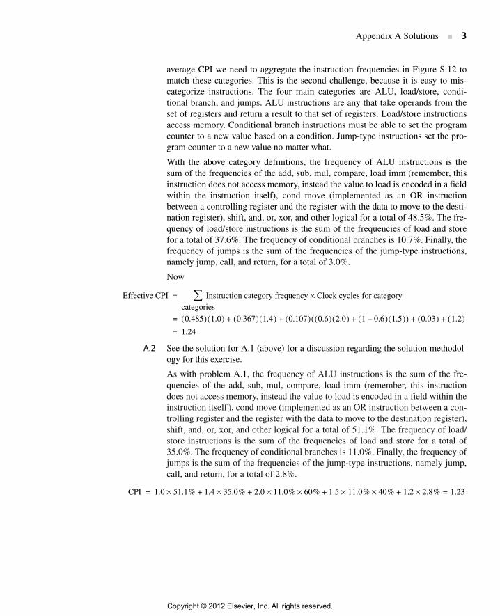
average CPI we need to aggregate the instruction frequencies in Figure S.12 tomatch these categories. This is the second challenge, because it is easy to mis-categorize instructions. The four main categories are ALU, load/store, condi-tional branch, and jumps. ALU instructions are any that take operands from theset of registers and return a result to that set of registers. Load/store instructionsaccess memory. Conditional branch instructions must be able to set the programcounter to a new value based on a condition. Jump-type instructions set the pro-gram counter to a new value no matter what.
With the above category definitions, the frequency of ALU instructions is thesum of the frequencies of the add, sub, mul, compare, load imm (remember, thisinstruction does not access memory, instead the value to load is encoded in a fieldwithin the instruction itself), cond move (implemented as an OR instructionbetween a controlling register and the register with the data to move to the desti-nation register), shift, and, or, xor, and other logical for a total of 48.5%. The fre-quency of load/store instructions is the sum of the frequencies of load and storefor a total of 37.6%. The frequency of conditional branches is 10.7%. Finally, thefrequency of jumps is the sum of the frequencies of the jump-type instructions,namely jump, call, and return, for a total of 3.0%.
Now
A.2 See the solution for A.1 (above) for a discussion regarding the solution methodol-ogy for this exercise.
As with problem A.1, the frequency of ALU instructions is the sum of the fre-quencies of the add, sub, mul, compare, load imm (remember, this instructiondoes not access memory, instead the value to load is encoded in a field within theinstruction itself ), cond move (implemented as an OR instruction between a con-trolling register and the register with the data to move to the destination register),shift, and, or, xor, and other logical for a total of 51.1%. The frequency of load/store instructions is the sum of the frequencies of load and store for a total of35.0%. The frequency of conditional branches is 11.0%. Finally, the frequency ofjumps is the sum of the frequencies of the jump-type instructions, namely jump,call, and return, for a total of 2.8%.
Effective CPI Instruction category frequency Clock cycles for category×categories∑=
0.485( ) 1.0( ) 0.367( ) 1.4( ) 0.107( ) 0.6( ) 2.0( ) 1 0.6–( ) 1.5( )+( ) 0.03( ) 1.2( )+ + + +=
1.24=
CPI 1.0 51.1% 1.4 35.0% 2.0 11.0% 60% 1.5 11.0% 40% 1.2 2.8% 1.23=×+××+××+×+×=
Copyright © 2012 Elsevier, Inc. All rights reserved.

4 ■ Solutions to Case Studies and Exercises
A.3 This exercise is similar to A.1 and A.2, but focuses on floating point intensiveprograms.
Instruction Average of gzip and perlbmk %
load 24.4
store 10.6
add 21.8
sub 3.8
mul –
compare 5.2
load imm 1.6
cond branch 11.0
cond move 1.5
jump 1.2
call 0.8
return 0.8
shift 1.3
and 5.3
or 6.8
xor 3.6
other logical 0.2
Figure S.13 MIPS dynamic instruction mix average for gzip and perlbmk.
Instruction Average of gzip and perlbmk %
Load 9.8
Store 2.4
Add 17.8
Sub 3.0
Mul 0.6
Compare –
load imm 5.6
cond branch 1.0
cond move –
Jump –
Call –
Return –
Shift 1.0
Figure S.14 Continued
Copyright © 2012 Elsevier, Inc. All rights reserved.

Appendix A Solutions ■ 5
ALU instructions: (17.8% + 3.0% + 0.6% + 5.6% + 1.0% + 0.9% + 4.1%) = 33.0%Load-stores: (9.4% + 2.4%) = 11.8%Conditional branches: 1.0%Jumps: 0%FP add: (8.6% + 6.2%) = 14.8%Load-store FP: (16.5% + 11.6%) = 28.1%Other FP: (1.4% + 0.4% + 0.4% + 0.8%) = 3.0%
CPI = 1.0 × 33.0% + 1.4 × 11.8% + 2.0 × 1.0% × 60% + 1.5 × 1.0% × 40% + 6.0× 8.2% + 4.0 × 14.8% + 20 × 0.2% + 1.5 × 28.1% + 2.0 × 3.0% = 2.12
A.4 This exercise is similar to A.3.
And 0.9
Or 4.1
Xor –
other logical –
load FP 16.5
store FP 11.6
add FP 8.6
sub FP 6.2
mul FP 8.2
div FP 0.2
move reg-reg FP 1.4
compare FP 0.4
cond mov FP 0.4
other FP 0.8
Figure S.14 MIPS dynamic instruction mix for lucas and swim.
Instruction Average of applu and art %
Load 16.0
Store 1.4
Add 30.2
Sub 1.2
Mul 1.2
Compare 3.7
load imm 6.8
cond branch 7.0
cond move 0.2
Jump –
Figure S.15 Continued
Copyright © 2012 Elsevier, Inc. All rights reserved.

6 ■ Solutions to Case Studies and Exercises
ALU instructions: (30.2% + 1.2% + 1.2% + 3.7% + 6.8% + 0.2% + 0.4% +1.0% + 1.6%) = 46.3%Load-stores: (16.0% + 1.4%) = 17.4%Conditional branches: 7.0%Jumps: 0%FP add: (3.4% + 1.4%) = 4.8%Load-store FP: (11.7% + 4.4%) = 16.1%Other FP: (0.8% + 0.4% + 0.3%) = 1.5%
CPI = 1.0 × 46.3% + 1.4 × 17.4% + 2.0 × 7.0% × 60% + 1.5 × 7.0% × 40% +6.0 × 6.4% + 4.0 × 4.8% + 20 × 0.4% + 1.5 × 16.1% + 2.0 × 1.5% = 1.76
A.5 Take the code sequence one line at a time.
Call –
Return –
Shift 0.4
And –
Or 1.0
Xor 1.6
other logical –
load FP 11.7
store FP 4.4
add FP 3.4
sub FP 1.4
mul FP 6.4
div FP 0.4
move reg-reg FP 0.8
compare FP 0.4
cond mov FP 0.3
other FP –
Figure S.15 MIPS dynamic instruction mix for applu and art.
1. A = B + C ;The operands here are given, not computed by the code, so copy propagation will not transform this statement.
2. B = A + C ;Here A is a computed value, so transform the code by substituting A = B + C to get
= B + C + C ;Now no operand is computed
3. D = A – B ;Both operands are computed so substitute for both to get
= (B + C) – (B + C + C) ;Simplify algebraically to get
= – C ;This is a given, not computed, operand
Copyright © 2012 Elsevier, Inc. All rights reserved.

Appendix A Solutions ■ 7
Copy propagation has increased the work in statement 2 from one addition totwo. It has changed the work in statement 3 from subtraction to negation, possi-bly a savings. The above suggests that writing optimizing compilers means incor-porating sophisticated trade-off analysis capability to control any optimizingsteps, if the best results are to be achieved.
A.6 No solution provided.
A.7 a. The point of this exercise is to highlight the value of compiler optimizations.In this exercise registers are not used to hold updated values; values are storedto memory when updated and subsequently reloaded. Because all theaddresses of all the variables (including all array elements) can fit in 16 bits,we can use immediate instructions to construct addresses. Figure S.16 showsone possible translation of the given C code fragment.
The number of instructions executed dynamically is the number of initializa-tion instructions plus the number of instructions in the loop times the numberof iterations:
Instructions executed = 2 + (16 × 101) = 1618
The number of memory-data references is a count of the load and storeinstructions executed:
Memory-data references executed = 0 + (8 × 101) = 808
ex_a_7: DADD R1,R0,R0 ;R0 = 0, initialize i = 0SW 7000(R0),R1 ;store i
loop: LD R1,7000(R0) ;get value of iDSLL R2,R1,#3 ;R2 = word offset of B[i]DADDI R3,R2,#3000 ;add base address of B to R2LD R4,0(R3) ;load B[i]LD R5,5000(R0) ;load CDADD R6,R4,R5 ;B[i] + CLD R1,7000(R0) ;get value of iDSLL R2,R1,#3 ;R2 = word offset of A[i]DADDI R7,R2,#1000 ;add base address of A to R2SD 0(R7),R6 ;A[i] ← B[i] + CLD R1,7000(R0) ;get value of iDADDI R1,R1,#1 ;increment iSD 7000(R0),R1 ;store iLD R1,7000(R0) ;get value of iDADDI R8,R1,#-101 ;is counter at 101?BNEZ R8,loop ;if not 101, repeat
Figure S.16 MIPS code to implement the C loop without using registers to holdupdated values for future use or to pass values to a subsequent loop iteration.
Copyright © 2012 Elsevier, Inc. All rights reserved.
8 ■ Solutions to Case Studies and Exercises
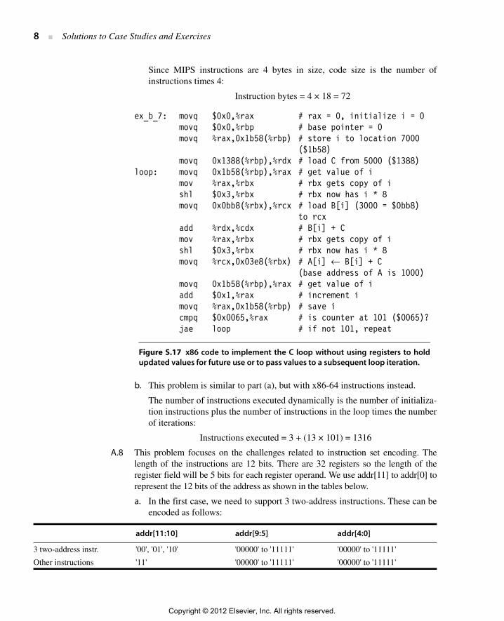
Since MIPS instructions are 4 bytes in size, code size is the number ofinstructions times 4:
Instruction bytes = 4 × 18 = 72
b. This problem is similar to part (a), but with x86-64 instructions instead.
The number of instructions executed dynamically is the number of initializa-tion instructions plus the number of instructions in the loop times the numberof iterations:
Instructions executed = 3 + (13 × 101) = 1316
A.8 This problem focuses on the challenges related to instruction set encoding. Thelength of the instructions are 12 bits. There are 32 registers so the length of theregister field will be 5 bits for each register operand. We use addr[11] to addr[0] torepresent the 12 bits of the address as shown in the tables below.
a. In the first case, we need to support 3 two-address instructions. These can beencoded as follows:
addr[11:10] addr[9:5] addr[4:0]
3 two-address instr. '00', '01', '10' '00000' to '11111' '00000' to '11111'
Other instructions '11' '00000' to '11111' '00000' to '11111'
ex_b_7: movq $0x0,%rax # rax = 0, initialize i = 0movq $0x0,%rbp # base pointer = 0movq %rax,0x1b58(%rbp) # store i to location 7000
($1b58) movq 0x1388(%rbp),%rdx # load C from 5000 ($1388)loop: movq 0x1b58(%rbp),%rax # get value of i mov %rax,%rbx # rbx gets copy of i shl $0x3,%rbx # rbx now has i * 8
movq 0x0bb8(%rbx),%rcx # load B[i] (3000 = $0bb8) to rcx
add %rdx,%cdx # B[i] + C mov %rax,%rbx # rbx gets copy of i shl $0x3,%rbx # rbx now has i * 8
movq %rcx,0x03e8(%rbx) # A[i] ← B[i] + C (base address of A is 1000)
movq 0x1b58(%rbp),%rax # get value of i add $0x1,%rax # increment i movq %rax,0x1b58(%rbp) # save i cmpq $0x0065,%rax # is counter at 101 ($0065)? jae loop # if not 101, repeat
Figure S.17 x86 code to implement the C loop without using registers to holdupdated values for future use or to pass values to a subsequent loop iteration.
Copyright © 2012 Elsevier, Inc. All rights reserved.
Appendix A Solutions ■ 9
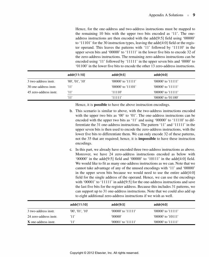
Hence, for the one-address and two-address instructions must be mapped tothe remaining 10 bits with the upper two bits encoded as ‘11’. The one-address instructions are then encoded with the addr[9:5] field using ‘00000’to ‘11101’ for the 30 instruction types, leaving the addr[4:0] field or the regis-ter operand. This leaves the patterns with ‘11’ followed by ‘11110’ in theupper seven bits and ‘00000’ to ‘11111’ in the lower five bits to encode 32 ofthe zero-address instructions. The remaining zero-address instructions can beencoded using ‘11’ followed by ‘11111’ in the upper seven bits and ‘0000’ to‘01100’ in the lower five bits to encode the other 13 zero-address instructions.
Hence, it is possible to have the above instruction encodings.
b. This scenario is similar to above, with the two-address instructions encodedwith the upper two bits as ‘00’ to ‘01’. The one-address instructions can beencoded with the upper two bits as ‘11’ and using ‘00000’ to ‘11110’ to dif-ferentiate the 31 one-address instructions. The pattern ‘11’ and ‘11111’ in theupper seven bits is then used to encode the zero-address instructions, with thelower five bits to differentiate them. We can only encode 32 of these patterns,not the 35 that are required; hence, it is impossible to have these instructionencodings.
c. In this part, we already have encoded three two-address instructions as above.Moreover, we have 24 zero-address instructions encoded as below with‘00000’ in the addr[9:5] field and ‘00000’ to ‘10111’ in the addr[4:0] field.We would like to fit as many one-address instructions as we can. Note that wecannot take advantage of any of the unused encodings with ‘11’ and ‘00000’in the upper seven bits because we would need to use the entire addr[4:0]field for the single address of the operand. Hence, we can use the encodingswith ‘00001’ to ‘11111’ in addr[9:5] for the one-address instructions and savethe last five bits for the register address. Because this includes 31 patterns, wecan support up to 31 one-address instructions. Note that we could also add upto eight additional zero-address instructions if we wish as well.
addr[11:10] addr[9:5] addr[4:0]
3 two-address instr. '00', '01', '10' '00000' to '11111' '00000' to '11111'
30 one-address instr. '11' '00000' to '11101' '00000' to '11111'
45 zero-address instr. '11' '11110' '00000' to '11111'
'11' '11111' '00000' to '01100'
addr[11:10] addr[9:5] addr[4:0]
3 two-address instr. '00', '01', '10' '00000' to '11111' '00000' to '11111'
24 zero-address instr. '11' '00000' '00000' to '10111'
X one-address instr. '11' '00001' to '11111' '00000' to '11111'
Copyright © 2012 Elsevier, Inc. All rights reserved.

10 ■ Solutions to Case Studies and Exercises
A.9
a. 1) Stack:Push A // one address appears in the instruction, code size = 8 bits (opcode) +64 bits (memory address) = 72 bits;Push B // one address appears in the instruction, code size = 72 bits;Add // zero address appears in the instruction, code size = 8 bits;Pop C // one address appears in the instruction, code size = 72 bits;
Total code size = 72 + 72 + 8 + 72 = 224 bits.
2) AccumulatorLoad A // one address appears in the instruction, code size = 8 bits (opcode) +64 bits (memory address) = 72 bits;Add B // one address appears in the instruction, code size = 72 bits;Store C // one address appears in the instruction, code size = 72 bits;
Total code size = 72 + 72 + 8 + 72 = 216 bits.
3) Register-memoryLoad R1, A // two addresses appear in the instruction, code size = 8 bits(opcode) + 6 bits (register address) + 64 bits (memory address) = 78 bits;Add R3, R1, B // three addresses appear in the instruction, code size = 8 bits(opcode) + 6 bits (register address) + 6 bits (register address) + 64 bits (mem-ory address) = 84 bits;Store R3,C // two addresses appear in the instruction, code size = 78 bits;
Total code size = 78 + 84 + 78 = 240 bits.
4) Register-registerLoad R1, A // two addresses appear in the instruction, code size = 8 bits(opcode) + 6 bits (register address) + 64 bits (memory address) = 78 bits;Load R2, B // two addresses appear in the instruction, code size = 78 bits;Add R3, R1, R2 // three addresses appear in the instruction, code size = 8 bits(opcode) + 6 bits (register address) + 6 bits (register address) + 6 bits (registeraddress) = 26 bits;Store R3, C // two addresses appear in the instruction, code size = 78 bits;
Total code size = 78 + 78 + 26 + 78 = 260 bits.
b. Assume all the data size are 64 bits. Assume there is no complier optimiza-tion.
Copyright © 2012 Elsevier, Inc. All rights reserved.

Appendix A Solutions ■ 11
1) Stack
The total code size is 672/8 = 84 bytes. The number of bytes of data moved toor from memory is 576/8 = 72 bytes. There are 3 overhead instructions. Thenumber of overhead data bytes is 24 bytes.
2) Accumulator
The total code size is 576/8 = 72 bytes. The number of bytes of data moved toor from memory is 512/8 = 64 bytes. There is 1 overhead instruction. Thenumber of overhead data bytes is 8 bytes.
CodeDestroyed
data OverheadCode size
(bits)Size of mem
data
Push A no 72 64
Push B no 72 64
Add A and B 8
Pop C C 72 64
Push E no 72 64
Push A no yes 72 64
Sub A and E 8
Pop D D 72 64
Push C no yes 72 64
Push D no yes 72 64
Add C and D 8
Pop F no 72 64
Total 672 576
CodeDestroyed
data OverheadCode size
(bits)Size of mem
data
Load A 72 64
Add B A 72 64
Store C 72 64
Load A C yes 72 64
Sub E A 72 64
Store D 72 64
Add C D 72 64
Store F 72 64
Total 576 512
Copyright © 2012 Elsevier, Inc. All rights reserved.
12 ■ Solutions to Case Studies and Exercises
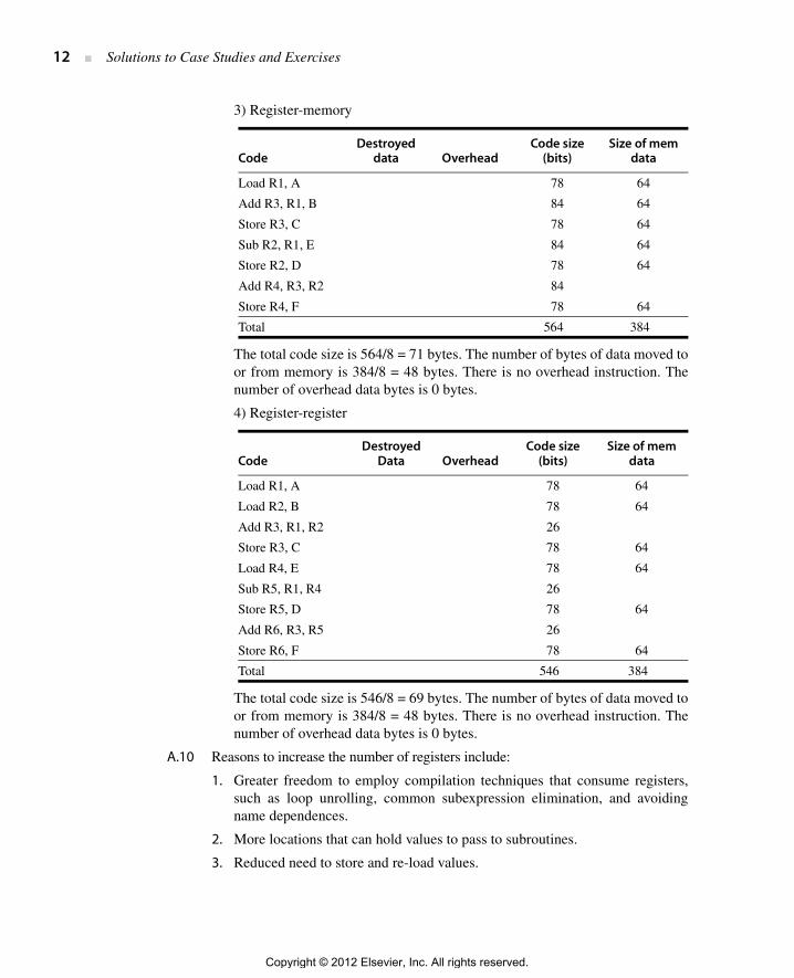
3) Register-memory
The total code size is 564/8 = 71 bytes. The number of bytes of data moved toor from memory is 384/8 = 48 bytes. There is no overhead instruction. Thenumber of overhead data bytes is 0 bytes.
4) Register-register
The total code size is 546/8 = 69 bytes. The number of bytes of data moved toor from memory is 384/8 = 48 bytes. There is no overhead instruction. Thenumber of overhead data bytes is 0 bytes.
A.10 Reasons to increase the number of registers include:
1. Greater freedom to employ compilation techniques that consume registers,such as loop unrolling, common subexpression elimination, and avoidingname dependences.
2. More locations that can hold values to pass to subroutines.
3. Reduced need to store and re-load values.
CodeDestroyed
data OverheadCode size
(bits)Size of mem
data
Load R1, A 78 64
Add R3, R1, B 84 64
Store R3, C 78 64
Sub R2, R1, E 84 64
Store R2, D 78 64
Add R4, R3, R2 84
Store R4, F 78 64
Total 564 384
CodeDestroyed
Data OverheadCode size
(bits)Size of mem
data
Load R1, A 78 64
Load R2, B 78 64
Add R3, R1, R2 26
Store R3, C 78 64
Load R4, E 78 64
Sub R5, R1, R4 26
Store R5, D 78 64
Add R6, R3, R5 26
Store R6, F 78 64
Total 546 384
Copyright © 2012 Elsevier, Inc. All rights reserved.

Appendix A Solutions ■ 13
Reasons not to increase the number of registers include:
1. More bits needed to represent a register name, thus increasing the overall sizeof an instruction or reducing the size of some other field(s) in the instruction.
2. More CPU state to save in the event of an exception.
3. Increased chip area and increased power consumption.
A.11 This program illustrates how alignment impacts data structures in C/C++. Note thatthe struct definition is for C++ because it includes a bool type.
So, on a 32-bit machine:
This structure requires 1 + 1 + 4 + 8 + 2 + 4 + 8 + 4 + 4 + 4 = 40 bytes in total.Because of alignment requirements, the char and bool will be padded by twobytes so the int c is aligned. Similarly, the short e is also padded by two bytes sothe float f will be aligned. Hence, as written this C++ struct will require 44 byteson a 32-bit processor.
With rearranging the order of the elements, the minimum size required to storethe structure achieves this 40 byte total. We can do this by placing the largest ele-ments in the struct first followed in order by the smaller elements. See below:
struct foo { double d; double g; char * cptr; float * fptr; int c; int x; float f; short e; char a; bool b;}
On a 64-bit processor, this structure requires 1 + 1 + 4 + 8 + 2 + 4 + 8 + 8 + 8 + 4 = 48bytes in total.
Data typeData size on 32-bit
machine (bytes)Data size on 64-bit
machine (bytes)
char 1 1
bool 1 1
int 4 4
long 4 8
double 8 8
short 2 2
float 4 4
pointer 4 8
Copyright © 2012 Elsevier, Inc. All rights reserved.

14 ■ Solutions to Case Studies and Exercises
As with the 32-bit processor, two bytes are added after the bool b so the int c isaligned and two more are added after the short e so the float f is aligned. Finally,the final int x has four bytes added to the end to make the struct aligned withan 8 byte boundary. Hence, the original struct requires 56 bytes on a 64-bitprocessor. By reordering the contents of the struct in the same manner as withthe 32-bit machine above, the additional padding requirements are eliminatedand the 48 byte size can be achieved for the struct.
A.12 No solution provided.
A.13 No solution provided.
A.14 No solution provided.
A.15 No solution provided.
A.16 No solution provided.
A.17 No solution provided.
A.18 Accumulator architecture code:
Load B ;Acc ← BAdd C ;Acc ← Acc + CStore A ;Mem[A] ← AccAdd C ;Acc ← "A” + CStore B ;Mem[B] ← AccNegate ;Acc ← − AccAdd A ;Acc ← “− B” + AStore D ;Mem[D] ← Acc
Memory-memory architecture code:
Add A, B, C ;Mem[A] ← Mem[B] + Mem[C]Add B, A, C ;Mem[B] ← Mem[A] + Mem[C]Sub D, A, B ;Mem[D] ← Mem[A] − Mem[B]Stack architecture code: (TOS is top of stack, NTTOS is the next to the top ofstack, and * is the initial contents of TOS)
Push B ;TOS ← Mem[B], NTTOS ← *Push C ;TOS ← Mem[C], NTTOS ← TOSAdd ;TOS ← TOS + NTTOS, NTTOS ← *Pop A ;Mem[A] ← TOS, TOS ← *Push A ;TOS ← Mem[A], NTTOS ← *Push C ;TOS ← Mem[C], NTTOS ← TOSAdd ;TOS ← TOS + NTTOS, NTTOS ← *Pop B ;Mem[B] ← TOS, TOS ← *Push B ;TOS ← Mem[B], NTTOS ← *Push A ;TOS ← Mem[A], NTTOS ← TOSSub ;TOS ← TOS − NTTOS, NTTOS ← *Pop D ;Mem[D] ← TOS, TOS ← *
Load-store architecture code:
Load R1,B ;R1 ← Mem[B]Load R2,C ;R2 ← Mem[C]
Copyright © 2012 Elsevier, Inc. All rights reserved.

Appendix A Solutions ■ 15
Add R3,R1,R2 ;R3 ← R1 + R2 = B + CAdd R1,R3,R2 ;R1 ← R3 + R2 = A + CSub R4,R3,R1 ;R4 ← R3 − R1 = A − BStore A,R3 ;Mem[A] ← R3Store B,R1 ;Mem[B] ← R1Store D,R4 ;Mem[D] ← R4
A.19 This problem is similar to A.7, but students are asked to consider how to implementa looping structure for the different architecture styles as in problem A.18. Weassume A, B, C, and i are held in memory using addresses 1000, 3000, 5000, and7000 as in problem A.7.
For the register-register case, we can use the MIPS code from A.7. In this case weassume the locations for each of the variables as with A.7.a.
ex_19_1: DADD R1,R0,R0 ;R0 = 0, initialize i = 0SW 7000(R0),R1 ;store i
loop: LD R1,7000(R0) ;get value of iDSLL R2,R1,#3 ;R2 = word offset of B[i]DADDI R3,R2,#3000 ;add base address of B to R2LD R4,0(R3) ;load B[i]LD R5,5000(R0) ;load CDADD R6,R4,R5 ;B[i] + CLD R1,7000(R0) ;get value of iDSLL R2,R1,#3 ;R2 = word offset of A[i]DADDI R7,R2,#1000 ;add base address of A to R2SD 0(R7),R6 ;A[i] ← B[i] + CLD R1,7000(R0) ;get value of iDADDI R1,R1,#1 ;increment iSD 7000(R0),R1 ;store iLD R1,7000(R0) ;get value of iDADDI R8,R1,#-101 ;is counter at 101?BNEZ R8,loop ;if not 101, repeat
For the register-memory case, we can use the x86-64 code as in A.7 b):
ex_7_2: movq $0x0,%rax # rax = 0, initialize i = 0movq $0x0,%rbp # base pointer = 0movq %rax,0x1b58(%rbp) # store i to location 7000
($1b58)movq 0x1388(%rbp),%rdx # load C from 5000 ($1388)
loop: movq 0x1b58(%rbp),%rax # get value of imov %rax,%rbx # rbx gets copy of ishl $0x3,%rbx # rbx now has i * 8movq 0x0bb8(%rbx),%rcx # load B[i] (3000 = $0bb8)
to rcxadd %rdx,%cdx # B[i] + Cmov %rax,%rbx # rbx gets copy of ishl $0x3,%rbx # rbx now has i * 8movq %rcx,0x03e8(%rbx) # A[i] ← B[i] + C (base
address of A is 1000)
Copyright © 2012 Elsevier, Inc. All rights reserved.

16 ■ Solutions to Case Studies and Exercises
movq 0x1b58(%rbp),%rax # get value of iadd $0x1,%rax # increment imovq %rax,0x1b58(%rbp) # save icmpq $0x0065,%rax # is counter at 101 ($0065)?jae loop # if not 101, repeat
For the stack machine case, we will add an indirect addressing mode where anaddress can placed on the stack. If a pushind (push with indirect addressing) isused, it will take the value from the top of the stack as the address for the push.For popind (pop with indirect addressing), the top of the stack is the addressfor the target and the next entry on the stack is the value to be saved. We alsoassume a jle instruction exists that takes the top three elements from the stackand junps to the target (top of stack) if the second element is greater than thethird element from the top of the stack (the third is less than or equal to thesecond).
ex_7_3: push 0 # put 0 on stackpop i # save i
loop: push i # put i on stackpush 3 # push 3shl # shift left by three (multiply by 8)pop tmp # temporary storage for i*8push tmp # load i*8push 3000 # load address of Badd # compute address of B[i]pushind # push with indirect addressing to get B[i]push C # read value of Cadd # get sum of B[i] + Cpush 1000 # load address of Apush tmp # load i*8 (offset for A)add # compute address of A[i]popind # pop with indirect addressing to assign sum
to A[i]push i # get value of iadd 1 # increment by onepop i # save value of i push i # get value of i push 100 # termination valuepush loop # push loop target addressjle # jump to next iteration if i <= 100
For the accumulator machine, we can use the accumulator to compute an addressfor indirect addressing when we read a value from memory. Unfortunately, whenwe want to compute an address for saving a value to memory we will lose thevalue to be saved while computing the address! So A[i] = expression becomeshard to express. One could either add another register to support indirect address-ing, which makes the machine no longer fit into the accumulator category. Alter-nately, one can employ self-modifying code to compute the A[i] address and thenupdate the immediate field for direct addressing. To do this, we can assume that
Copyright © 2012 Elsevier, Inc. All rights reserved.
Appendix A Solutions ■ 17
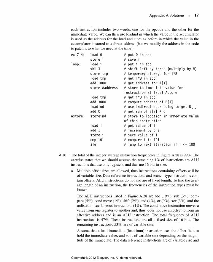
each instruction includes two words, one for the opcode and the other for theimmediate value. We can then use loadind in which the value in the accumulatoris used as the address for the load and store as before in which the value in theaccumulator is stored to a direct address (but we modify the address in the codeto patch it to what we need at the time).
ex_7_4: load 0 # put 0 in accstore i # save i
loop: load i # put i in accshl 3 # shift left by three (multiply by 8)store tmp # temporary storage for i*8load tmp # get i*8 in accadd 1000 # get address for A[i]store Aaddress # store to immediate value for
instruction at label Astoreload tmp # get i*8 in accadd 3000 # compute address of B[i]loadind # use indirect addressing to get B[i]add C # get sum of B[i] + C
Astore: storeind # store to location in immediate valueof this instruction
load i # get value of iadd 1 # increment by onestore i # save value of i cmp 101 # compare i to 101jle # jump to next iteration if i <= 100
A.20 The total of the integer average instruction frequencies in Figure A.28 is 99%. Theexercise states that we should assume the remaining 1% of instructions are ALUinstructions that use only registers, and thus are 16 bits in size.
a. Multiple offset sizes are allowed, thus instructions containing offsets will beof variable size. Data reference instructions and branch-type instructions con-tain offsets; ALU instructions do not and are of fixed length. To find the aver-age length of an instruction, the frequencies of the instruction types must beknown.
The ALU instructions listed in Figure A.28 are add (19%), sub (3%), com-pare (5%), cond move (1%), shift (2%), and (4%), or (9%), xor (3%), and theunlisted miscellaneous instructions (1%). The cond move instruction moves avalue from one register to another and, thus, does not use an offset to form aneffective address and is an ALU instruction. The total frequency of ALUinstructions is 47%. These instructions are all a fixed size of 16 bits. Theremaining instructions, 53%, are of variable size.
Assume that a load immediate (load imm) instruction uses the offset field tohold the immediate value, and so is of variable size depending on the magni-tude of the immediate. The data reference instructions are of variable size and
Copyright © 2012 Elsevier, Inc. All rights reserved.

18 ■ Solutions to Case Studies and Exercises
comprise load (26%), store (10%), and load imm (2%), for a total of 38%.The branch-type instructions include cond branch (12%), jump (1%), call(1%), and return (1%), for a total of 15%.
For instructions using offsets, the data in Figure A.31 provides frequencyinformation for offsets of 0, 8, 16, and 24 bits. Figure 2.42 lists the cumula-tive fraction of references for a given offset magnitude. For example, to deter-mine what fraction of branch-type instructions require an offset of 16 bits(one sign bit and 15 magnitude bits) find the 15-bit magnitude offset branchcumulative percentage (98.5%) and subtract the 7-bit cumulative percentage(85.2%) to yield the fraction (13.3%) of branches requiring more than 7 mag-nitude bits but less than or equal to 15 magnitude bits, which is the desiredfraction. Note that the lowest magnitude at which the cumulative percentageis 100% defines an upper limit on the offset size. For data reference instruc-tions a 15-bit magnitude captures all offset values, and so an offset of largerthan 16 bits is not needed. Possible data-reference instruction sizes are 16, 24,and 32 bits. For branch-type instructions 19 bits of magnitude are necessaryto handle all offset values, so offset sizes as large as 24 bits will be used. Pos-sible branch-type instruction sizes are 16, 24, 32, and 40 bits.
Employing the above, the average lengths are as follows.
b. With a 24-bit fixed instruction size, the data reference instructions requiring a16-bit offset and the branch instructions needing either a 16-bit or 24-bit off-set cannot be performed by a single instruction. Several alternative imple-mentations are or may be possible.
First, a large-offset load instruction might be eliminated by a compiling opti-mization. If the value was loaded earlier it may be possible, by placing ahigher priority on that value, to keep it in a register until the subsequent use.Or, if the value is the stored result of an earlier computation, it may be possi-ble to recompute the value from operands while using no large-offset loads.Because it might not be possible to transform the program code to accom-plish either of these schemes at lower cost than using the large-offset load,let’s assume these techniques are not used.
For stores and branch-type instructions, compilation might be able to rear-range code location so that the store effective address or target instructionaddress is closer to the store or branch-type instruction, respectively, and thusrequire a smaller offset. Again, let’s assume that this is not attempted.
ALU length = 16 bits
Data-reference length = 16 × 0.304 + 24 × (0.669 – 0.304) + 32 × (1.0 – 0.669)
= 24.2 bits
Branch-type length = 16 × 0.001 + 24 × (0.852 – 0.001) + 32 × (0.985 – 0.852)
= 25.3 bits
Average length = 16 × 0.47 + 24.2 × 0.38 + 25.3 × 0.15= 20.5 bits
Copyright © 2012 Elsevier, Inc. All rights reserved.
Appendix A Solutions ■ 19
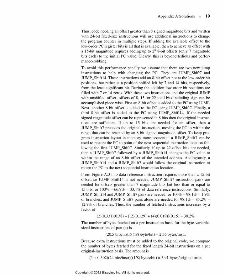
Thus, code needing an offset greater than 8 signed magnitude bits and writtenwith 24-bit fixed-size instructions will use additional instructions to changethe program counter in multiple steps. If adding the available offset to thelow-order PC register bits is all that is available, then to achieve an offset witha 15-bit magnitude requires adding up to 28 8-bit offsets (only 7 magnitudebits each) to the initial PC value. Clearly, this is beyond tedious and perfor-mance-robbing.
To avoid this performance penalty we assume that there are two new jumpinstructions to help with changing the PC. They are JUMP_Shift7 andJUMP_Shift14. These instructions add an 8-bit offset not at the low-order bitpositions, but rather at a position shifted left by 7 and 14 bits, respectively,from the least significant bit. During the addition low order bit positions arefilled with 7 or 14 zeros. With these two instructions and the original JUMPwith unshifted offset, offsets of 8, 15, or 22 total bits including sign can beaccomplished piece wise. First an 8-bit offset is added to the PC using JUMP.Next, another 8-bit offset is added to the PC using JUMP_Shift7. Finally, athird 8-bit offset is added to the PC using JUMP_Shift14. If the neededsigned magnitude offset can be represented in 8 bits then the original instruc-tions are sufficient. If up to 15 bits are needed for an offset, then aJUMP_Shift7 precedes the original instruction, moving the PC to within therange that can be reached by an 8-bit signed magnitude offset. To keep pro-gram instruction layout in memory more sequential a JUMP_Shift7 can beused to restore the PC to point of the next sequential instruction location fol-lowing the first JUMP_Shift7. Similarly, if up to 22 offset bits are needed,then a JUMP_Shift7 followed by a JUMP_Shift14 changes the PC value towithin the range of an 8-bit offset of the intended address. Analogously, aJUMP_Shift14 and a JUMP_Shift7 would follow the original instruction toreturn the PC to the next sequential instruction location.
From Figure A.31 no data reference instruction requires more than a 15-bitoffset, so JUMP_Shift14 is not needed. JUMP_Shift7 instruction pairs areneeded for offsets greater than 7 magnitude bits but less than or equal to15 bits, or 100% – 66.9% = 33.1% of data reference instructions. Similarly,JUMP_Shift14 and JUMP_Shift7 pairs are needed for 100% – 98.1% = 1.9%of branches, and JUMP_Shift7 pairs alone are needed for 98.1% – 85.2% =12.9% of branches. Thus, the number of fetched instructions increases by afactor of
(2)(0.331)(0.38) + [(2)(0.129) + (4)(0.019)](0.15) = 30.2%
The number of bytes fetched on a per-instruction basis for the byte-variable-sized instructions of part (a) is
(20.5 bits/instr)((1/8)byte/bit) = 2.56 bytes/instr.
Because extra instructions must be added to the original code, we comparethe number of bytes fetched for the fixed length 24-bit instructions on a peroriginal-instruction basis. The amount is
(1 + 0.302)(24 bits/instr)((1/8) bytes/bit) = 3.91 bytes/original instr.
Copyright © 2012 Elsevier, Inc. All rights reserved.
20 ■ Solutions to Case Studies and Exercises
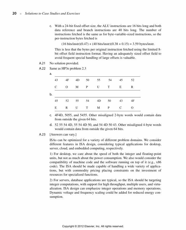
c. With a 24-bit fixed offset size, the ALU instructions are 16 bits long and bothdata reference and branch instructions are 40 bits long. The number ofinstructions fetched is the same as for byte-variable-sized instructions, so theper-instruction bytes fetched is
(16 bits/instr)(0.47) + (40 bits/instr)(0.38 + 0.15) = 3.59 bytes/instr.
This is less that the bytes per original instruction fetched using the limited 8-bit offset field instruction format. Having an adequately sized offset field toavoid frequent special handling of large offsets is valuable.
A.21 No solution provided.
A.22 Same as HP3e problem 2.3
a.
b.
c. 4F4D, 5055, and 5455. Other misaligned 2-byte words would contain datafrom outside the given 64 bits.
d. 52 55 54 4D, 55 54 4D 50, and 54 4D 50 43. Other misaligned 4-byte wordswould contain data from outside the given 64 bits.
A.23 [Answers can vary.]
ISAs can be optimized for a variety of different problem domains. We considerdifferent features in ISA design, considering typical applications for desktop,server, cloud, and embedded computing, respectively.
1) For desktop, we care about the speed of both the integer and floating-pointunits, but not as much about the power consumption. We also would consider thecompatibility of machine code and the software running on top of it (e.g., x86code). The ISA should be made capable of handling a wide variety of applica-tions, but with commodity pricing placing constraints on the investment ofresources for specialized functions.
2) For servers, database applications are typical, so the ISA should be targetinginteger computations, with support for high throughput, multiple users, and virtu-alization. ISA design can emphasize integer operations and memory operations.Dynamic voltage and frequency scaling could be added for reduced energy con-sumption.
43 4F 4D 50 55 54 45 52
C O M P U T E R
45 52 55 54 4D 50 43 4F
E R U T M P C O
Copyright © 2012 Elsevier, Inc. All rights reserved.

Appendix A Solutions ■ 21
3) Cloud computing ISAs should provide support for virtualization. Integer oper-ation and memory management will be important. Power savings and facilitiesfor easier system monitoring will be important for large data centers. Securityand encryption of user data will be important, so ISAs may provide support forthese concerns.
4) Power consumption is a big concern in embedded computing. Price is alsoimportant. The embedded ISAs may provide facilities for sensing and controllingdevices with special instructions and/or registers, analog to digital and digital toanalog converters, and interfaces to specialized, application-specific functions.The ISA may omit floating point, virtual memory, caching, or other performanceoptimizations to save energy or cost.
Copyright © 2012 Elsevier, Inc. All rights reserved.