appendix a tricon adapter installation · pdf fileboh-pm-02-a appendix a rev. 5.0 1 tricon...
TRANSCRIPT

BOH-PM-02-A Appendix A Rev. 5.0
FPU® SYSTEMS OPERATION MANUAL (INCLUDING REPAIR PARTS & SPECIAL TOOL LIST)
STANDARD AND SPECIALIZED FPU MODULES BOH FPU Field Pack-up Units
Appendix A
TRICON ADAPTER INSTALLATION PROCEDURES

BOH-PM-02-A Appendix A Rev. 5.0
This page was intentionally left blank

BOH-PM-02-A Appendix A Rev. 5.0
1
TRICON ADAPTER
Installation Procedures
BOH FPU® Systems BOH ENVIRONMENTAL LLC
14520 Avion Parkway, Suite 220 Chantilly, VA 20151
POC Jim Stokes (703) 449-6020 http://www.bohfpusystems.com

BOH-PM-02-A Appendix A Rev. 5.0
2
NOTE There are several manufacturers of TRICONs. Tiedown points and availability of container connector brackets may vary between containers. The following procedure is specifically for a Seabox TRICON container, but the installation concepts provided should suffice for other TRICON models as well. Refer to contact information on page 1 for any questions pertaining to the TRICON adapter product or these installation procedures. Parts List:
Required Tools:
Tape Measure
¾-inch wrench
¾-inch socket and driver
DESCRIPTION QUANTITY
Bolt "J" 1/2 - 13 x 7L 2
Bolt , Hex, ZP, GR 8, 1/2 - 13 x 1-1/2 3
Washer, Hillside Galv. 2
Hook Plate 2
Nut, Hex, ZP, GR8, 1/2 - 13 x 2L 8
Bolt, Hex, ZP, GR8, 1/2 - 13 x 2L 1
Positioner Plate 1
Tricon Washer 1
Washer Flat, 1/2" Heavy 5
Washer Locking Heavy Split, ZP 1/2 2
J-BOLTS
HILLSIDE
WASHERS
HOOK PLATE

BOH-PM-02-A Appendix A Rev. 5.0
3
TRICON STORAGE BRACKETS
NOTE
There are several manufacturers of TRICONs. Some models have one container connector storage bracket mounted to the inside of one door (one side of the container) and some models have two (one on both sides of the container). For models that have only one storage bracket and when installing only one pair of adapters, ensure the adapters are installed on the side that do not have these brackets. When installing two pairs of adapters or for models that are equipped with two storage brackets (one each side), the brackets will have to be removed to prevent interference with the FPU Storage Modules. Have maintenance cut and grind the brackets from the doors. TRICON connectors may be stored within the container.
TRICON CONNECTOR STORAGE BRACKETS

BOH-PM-02-A Appendix A Rev. 5.0
4
INSTALLING THE TRICON ADAPTERS
WARNING
Use proper lifting techniques when lifting the TRICON adapter. Use work gloves when handling the adapter. Never use fingers to align the bolt holes. Ensure there is proper footing when moving, lifting or positioning the adapter. Failure to comply may result in injury.
1. Using two personnel, lift the first adapter and place it near the wall on the right side of the
container with the red release handle facing outward. Align the adapter front 2” inside the
front edge of the TRICON container opening.
2. Install jack bolt and nut in between adapters near the front and back. 3. Finger tighten bolt head until it contacts the nut.
NOTE Jack bolt will be extended in a later step once the second adapter is in place.
RED RELEASE HANDLE

BOH-PM-02-A Appendix A Rev. 5.0
5
4. Using two personnel, lift the second adapter and position it on the left of the first adapter with the red handle facing outward.
5. Ensure the metal strip of the left hand adapter is positioned and overlapping the right hand
adapter. 6. With a metal rod or pry bar, align all the bolt holes. 7. Place the connecting U bracket over the overlapping adapters.
Connecting the Second Adapter
8. Align the U bracket over the second hole from the front and back. 9. Align the bracket holes and place the bolts, lock washers and flat washers in the bolt holes. 10. Place the flat washers and nuts underneath on the bolts and finger tighten.
OVERLAP STRIP
RIGHT ADAPTER
LEFT ADAPTER
U BRACKET
U BRACKET
BOH-PM-02-A Appendix A Rev. 5.0
6
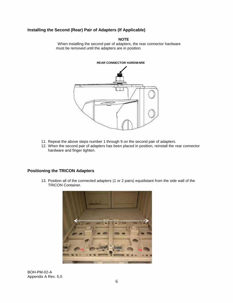
Installing the Second (Rear) Pair of Adapters (If Applicable)
NOTE When installing the second pair of adapters, the rear connector hardware
must be removed until the adapters are in position.
11. Repeat the above steps number 1 through 9 on the second pair of adapters. 12. When the second pair of adapters has been placed in position, reinstall the rear connector
hardware and finger tighten.
Positioning the TRICON Adapters
13. Position all of the connected adapters (1 or 2 pairs) equidistant from the side wall of the
TRICON Container.
REAR CONNECTOR HARDWARE

BOH-PM-02-A Appendix A Rev. 5.0
7
14. Position each of the front corners of the adapters (1 or 2 pairs) at least 2” inside the front door edge to permit the door to close. Check dimension at left and right front corners as shown in picture.
15. When two pairs of adapters are positioned back to back, tighten the left and right side rear connector bolts with a ¾” open end wrench.

BOH-PM-02-A Appendix A Rev. 5.0
8
SECURING THE TRICON ADAPTERS The adapters are secured to the TRICON containers that have welded tie-down points or floor rings by means of an adjustable J hook device.
NOTE
Eight J bolts are required when installing four adapters
1. When installing the J hook bolts, select a hole to tilt the device about 20 to 30 degrees
toward the center. 2. Feed each J hook bolt through the hole engaging the ring and place the hillside washer, flat
washer, adjustment nut and Jam nut on the bolt and finger tighten.
NOTE For those TRICON containers without floor rings, hook plates
are provided to attach to the side wall brackets.
ADJUSTABLE J HOOK BOLT AND WELDED FLOOR RING
20 TO 30 DEGREES

BOH-PM-02-A Appendix A Rev. 5.0
9
3. Progressively tighten each adjustment nut on all J Bolts until the adapters are secured in
place, and then tighten the jam nuts to prevent the J Bolts from loosening. 4. Verify adapters are centered in the container and tighten center U-bracket nuts. 5. Tighten J-bolt adjustment nuts using alternating pattern from both sides of the container. 6. Tighten J-bolt jam nuts. 7. With a ¾” open end wrench, extend each of the jack bolts with a counter clockwise rotation
until the bolt is snug with the opposing adapter. This will create opposing tension between the adapters.
8. With the ¾” open end wrench, tighten the Jam nut to prevent the jack bolts from coming loose.
HILLSIDE WASHER
ADJUSTMENT NUT AND WASHER
J HOOK BOLT
HOOK PLATE
JAM NUT
OPPOSING TENSION JAM NUT

BOH-PM-02-A Appendix A Rev. 5.0
10
9. Check all hardware with a ¾” wrench to ensure that they are tight and there is no movement
of the adapters.
JAM NUT
JACK BOLT
JAM NUT
U BRACKET AND HARDWARE

BOH-PM-02-A Appendix A Rev. 5.0
11
LOADING MODULES ONTO TRICON ADAPTERS
WARNING
Ground guides and the MHE operators must maintain direct line of sight and ensure that personnel are clear of the containers during this operation.
1. Before installing modules, pull red handle on adapters to open lock device. 2. Using ground guides, maneuver module with forklift into position and lower onto adapter. 3. Remove forklift. 4. Push in red handle to lock the module in place. 5. Repeat as necessary for loading modules onto other adapters.
CAUTION
Inspect module to ensure it is locked in place before transport. Failure to do so may result in damage to equipment.
END OF TRICON ADAPTER INSTALLATION PROCEDURES