application description y 04/2014 avoiding vibration in ... · application description y 04/2014...
TRANSCRIPT

http://support.automation.siemens.com/WW/view/en/78452062
Application description 04/2014
Avoiding vibration in slewinggear piecesSINUMERIK 828D, 840D sl

Warranty and liability
Avoiding vibrationEntry-ID: 78452062, V2.0, 04/2014 2
Siem
ens
AGC
opyr
ight
year
Allr
ight
sre
serv
ed
Warranty and liability
Note The Application Examples are not binding and do not claim to be completeregarding the circuits shown, equipping and any eventuality. The ApplicationExamples do not represent customer-specific solutions. They are only intendedto provide support for typical applications. You are responsible for ensuring thatthe described products are used correctly. These application examples do notrelieve you of the responsibility to use safe practices in application, installation,operation and maintenance. When using these Application Examples, yourecognize that we cannot be made liable for any damage/claims beyond theliability clause described. We reserve the right to make changes to theseApplication Examples at any time without prior notice.If there are any deviations between the recommendations provided in theseapplication examples and other Siemens publications – e.g. Catalogs – thecontents of the other documents have priority.
We do not accept any liability for the information contained in this document.
Any claims against us – based on whatever legal reason – resulting from the use ofthe examples, information, programs, engineering and performance data etc.,described in this Application Example shall be excluded. Such an exclusion shallnot apply in the case of mandatory liability, e.g. under the German Product LiabilityAct (“Produkthaftungsgesetz”), in case of intent, gross negligence, or injury of life,body or health, guarantee for the quality of a product, fraudulent concealment of adeficiency or breach of a condition which goes to the root of the contract(“wesentliche Vertragspflichten”). The damages for a breach of a substantialcontractual obligation are, however, limited to the foreseeable damage, typical forthe type of contract, except in the event of intent or gross negligence or injury tolife, body or health. The above provisions do not imply a change of the burden ofproof to your detriment.
Any form of duplication or distribution of these Application Examples or excerptshereof is prohibited without the expressed consent of Siemens Industry Sector.
Securityinforma-tion
Siemens provides products and solutions with industrial security functions thatsupport the secure operation of plants, solutions, machines, equipment and/ornetworks. They are important components in a holistic industrial securityconcept. With this in mind, Siemens’ products and solutions undergo continuousdevelopment. Siemens recommends strongly that you regularly check forproduct updates.
For the secure operation of Siemens products and solutions, it is necessary totake suitable preventive action (e.g. cell protection concept) and integrate eachcomponent into a holistic, state-of-the-art industrial security concept. Third-partyproducts that may be in use should also be considered. For more informationabout industrial security, visit http://www.siemens.com/industrialsecurity.
To stay informed about product updates as they occur, sign up for a product-specific newsletter. For more information, visithttp://support.automation.siemens.com.

Table of contents
Avoiding vibrationEntry-ID: 78452062, V2.0, 04/2014 3
Siem
ens
AGC
opyr
ight
year
Allr
ight
sre
serv
ed
Table of contentsWarranty and liability ................................................................................................... 2
1 Task ..................................................................................................................... 4
2 Solution............................................................................................................... 5
2.1 Overview............................................................................................... 52.2 Programming ........................................................................................ 52.3 Setup Settings ...................................................................................... 92.4 Application .......................................................................................... 11
3 Principle of the ideal speed behavior ............................................................ 13
4 Contact.............................................................................................................. 15
5 History............................................................................................................... 16

1 Task2.1 Overview
Avoiding vibrationEntry-ID: 78452062, V2.0, 04/2014 4
Cop
yrig
htSi
emen
sAG
Cop
yrig
htye
arAl
lrig
hts
rese
rved
1 TaskDescription of the application
When machining long and slender workpieces which are often very sensitive tovibrations, the speed in critical areas should be set to a harmonic oscillation in acontrolled manner during the machining process. The aim should be to change thespindle speed such that the machining process is not impaired and no chatter marksare formed on the rotating surface.
Overview of the automation taskThe following figure shows an example of a workpiece, which is set to vibration by theunfavorable tension condition during the rotating process.
Figure 1-1 Clamped shaft

2 Solution2.1 Overview
Avoiding vibrationEntry-ID: 78452062, V2.0, 04/2014 5
Cop
yrig
htSi
emen
sAG
Cop
yrig
htye
arAl
lrig
hts
rese
rved
2 Solution2.1 Overview
DescriptionPermanent change in speed of the master spindle can eliminate any vibrationsoccurring in the slewing gear piece. When manually changing the spindle speed byusing the override, it is very difficult to create a harmonious vibration speed of themaster spindle. Therefore, a cycle which consists of two part subprograms (.SPF files)should be created. By selectively switching the cycle on and off, a harmonic vibrationspeed of the master spindle is forced. Both subprograms of the cycle form the basis forfuture use of the "OSZI" command, which can be safely used in the program GUIDE(G-code).
Required knowledgeBasic knowledge of the programGUIDE (G code) programming is required.
AdvantagesThis application provides the following benefits: Avoiding chatter marks on the workpiece Precision turning process on the workpiece is still possible
2.2 Programming
The subprograms OSZI.SPF (Fig. 2-1) and OSZIOFF.SPF (Fig. 2-2), which are used toturn the harmonic vibration at set speed on and off will be stored in the password-protected area of the system data / user cycles. This area is accessible only toauthorized, qualified personnel. The end-user should be responsible, act deliberatelyand cautiously, as the cycles described require changes to system data.

2 Solution2.2 Programming
Avoiding vibrationEntry-ID: 78452062, V2.0, 04/2014 6
Cop
yrig
htSi
emen
sAG
Cop
yrig
htye
arAl
lrig
hts
rese
rved
Figure 2-1 Cycle for turning on harmonic vibrations at set speed
Note The program for turning on harmonic vibrations is provided as a download and itneed not be created by you.
For a better overview of the programGUIDE for turning on harmonic vibration at setspeed is shown below:;CYCLE FOR TURNING ON HARMONIC VIBRATION;VERSION 1.0 / BEBA;TRANSFER_PARAMETER: 1. OSCILLATION TIME FACTOR,2. PROCENTFAKTORPROC OSZI (REAL _OSZI_TIME, REAL _PROCENT)DEF REAL _TIME_1,_S_1,_S_2,_S,_SP_S=$P_S[$P_MSNUM]_SP=(_S*_PROCENT)/100_S_1=_S+_SP_S_2=_S-_SP$AC_TIMER[1]=0_TIME_1=$AC_TIMER[1]ID=1 EVERY $AC_TIMER[1] >= (_TIME_1+_OSZI_TIME) DO S=_S_1ID=2 EVERY $AC_TIMER[1] <= (_TIME_1+_OSZI_TIME) DO S=_S_2ID=3 EVERY $AC_TIMER[1] >= (_TIME_1+(_OSZI_TIME*2-0.05)) DORET
1
2
34
9
56
7
8

2 Solution2.2 Programming
Avoiding vibrationEntry-ID: 78452062, V2.0, 04/2014 7
Cop
yrig
htSi
emen
sAG
Cop
yrig
htye
arAl
lrig
hts
rese
rved
Table 2 1 Explanation of the programming steps (turning on the harmonic vibration at set speed)
No. Action Note
1 TRANSFER_PARAMETER:1.OSCILLATION TIME FACTOR,2. PERCENTAGE_FACTOR
Comments area
2 PROC OSZI (REAL _OSZI_TIME,REAL_PROZENT)
Definition of the procedure name, the transferparameters and the necessary program runtimevariables
3 _S=$P_S[$P_MSNUM] Query of the current master spindle
4 _SP=(_S*_PROZENT)/100 Calculation of the spindle speed in relation to thepercentage value
5 _S_1 Upper speed limit6 _S_2 Lower speed limit7 $AC_TIMER[1]=0
_TIME_1=$AC_TIMER[1]Setting and stopping the timer
8 ID=1 EVERY $AC_TIMER[1] >=(_TIME_1+_OSZI_TIME) DO S=_S_1
ID=2 EVERY $AC_TIMER[1] <=(_TIME_1+_OSZI_TIME) DO S=_S_2
ID=3 EVERY $AC_TIMER[1] >=(_TIME_1+(_OSZI_TIME*2-0.05)) DO
Synchronous actions for changing the set value ofthe spindle
9 2-0.05 Correction factor of the set timer
Note The correction factor of the set timer is an empirical value. This prevents theharmonic vibration from exceeding the set upper or lower limit of the spindlespeed.
2 Solution2.2 Programming
Avoiding vibrationEntry-ID: 78452062, V2.0, 04/2014 8
Cop
yrig
htSi
emen
sAG
Cop
yrig
htye
arAl
lrig
hts
rese
rved
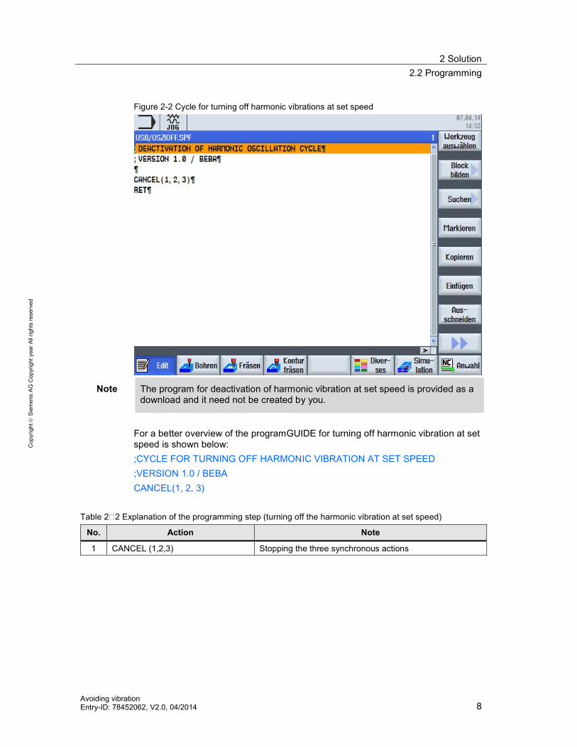
Figure 2-2 Cycle for turning off harmonic vibrations at set speed
Note The program for deactivation of harmonic vibration at set speed is provided as adownload and it need not be created by you.
For a better overview of the programGUIDE for turning off harmonic vibration at setspeed is shown below:;CYCLE FOR TURNING OFF HARMONIC VIBRATION AT SET SPEED;VERSION 1.0 / BEBACANCEL(1, 2, 3)
Table 2 2 Explanation of the programming step (turning off the harmonic vibration at set speed)
No. Action Note
1 CANCEL (1,2,3) Stopping the three synchronous actions

2 Solution2.3 Setup Settings
Avoiding vibrationEntry-ID: 78452062, V2.0, 04/2014 9
Cop
yrig
htSi
emen
sAG
Cop
yrig
htye
arAl
lrig
hts
rese
rved
2.3 Setup Settings
PrerequisiteIt must be ensured that the names of the used synchronous actions ID1 to ID3 areidentical in the startup and shutdown program (OSZI.SPF and OSZIOFF.SPF). Shouldother synchronous actions have this designation already, you must assign anumbering that is not used yet to these synchronous actions.
Setup SettingNote the following settings in the setup of the SINUMERIK control:1. Copy the generated subprograms OSZI.SPF and OSZIOFF.SPF
to the user cycle area as shown in Figure 2-3.
Figure 2-3 Inserting the OSC files in the user cycle area
Note The machine manufacturer or Siemens Service has the permission to access thesystem data area.
2 Solution2.3 Setup Settings
Avoiding vibrationEntry-ID: 78452062, V2.0, 04/2014 10
Cop
yrig
htSi
emen
sAG
Cop
yrig
htye
arAl
lrig
hts
rese
rved
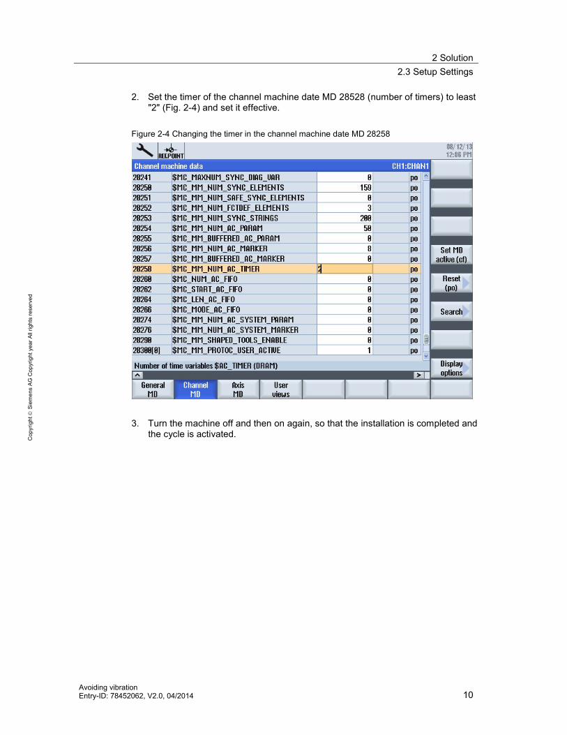
2. Set the timer of the channel machine date MD 28528 (number of timers) to least"2" (Fig. 2-4) and set it effective.
Figure 2-4 Changing the timer in the channel machine date MD 28258
3. Turn the machine off and then on again, so that the installation is completed andthe cycle is activated.

2 Solution2.4 Application
Avoiding vibrationEntry-ID: 78452062, V2.0, 04/2014 11
Cop
yrig
htSi
emen
sAG
Cop
yrig
htye
arAl
lrig
hts
rese
rved
2.4 Application
The Figure 2-4 shows the use of the vibration prevention function (OSC) in theSINUMERIK. OSC and OSZIOFF can be inserted into the respective workpieceprogram as high-level language commands. Only the percentage change in speed isentered within the parentheses. A change in the user cycles is not necessary from theperspective of the machine operator. Please note that this feature is intended only foruse in the programGUIDE and does not apply to ShopTurn.
Figure 2-4 Application of the OSC function in programGUIDE
Table 2 3 Explanation of the programming steps (vibration prevention program)
No. Action Note
1 G95 S1000 M3 The master spindle turns clockwise at 1000 rpm2 OSZI(2,10) The speed is set to 110% for a period of 2 seconds.3 Machining Is located here as the dummy for the machining process at
the workpiece.4 OSZIOFF Turning off the vibration5 G95 S1000 M3 Set new speed; otherwise, the last speed used will be
active. Either the upper or lower speed limit.

2 Solution2.4 Application
Avoiding vibrationEntry-ID: 78452062, V2.0, 04/2014 12
Cop
yrig
htSi
emen
sAG
Cop
yrig
htye
arAl
lrig
hts
rese
rved
Vibrations on the workpiece can be achieved by varying the constant speed.Therefore, the set value of the spindle changes constantly. Thus, the set value of thespindle speed fluctuates between a lower and upper limit back and forth within adefined period of time. In the current example, the selected set value of the spindlespeed ranges between 90% and 110% of rated speed selected. The time interval wasfixed at 2 seconds at an initial spindle speed of 1000 rpm.

3 Principle of the ideal speed behavior
Avoiding vibrationEntry-ID: 78452062, V2.0, 04/2014 13
Cop
yrig
htSi
emen
sAG
Cop
yrig
htye
arAl
lrig
hts
rese
rved
3 Principle of the ideal speed behaviorVibration and Master Spindle
Vibration acts only on the active master spindle and depends on its dynamics.
Reducing VibrationsIn order to reduce vibrations, the set value of the spindle speed is reduced orincreased by the percent factor after each time factor. The result is a vibration thatis strongly dependent on the dynamics of the spindle and the workpiece mass.There are no tables of values for this vibration behavior, thus the requiredparameters (spindle speed, time factor) for the material used must be determinedexperimentally.
Ideal Vibration BehaviorThe desired spindle behavior is illustrated in Figure 3-1. Constant fluctuation of thespindle speed between upper and lower limits specified by you (Section 2.4) resultsin a sinusoidal wave.
Figure 3-1 Ideal speed curve of the master spindle

3 Principle of the ideal speed behavior
Avoiding vibrationEntry-ID: 78452062, V2.0, 04/2014 14
Cop
yrig
htSi
emen
sAG
Cop
yrig
htye
arAl
lrig
hts
rese
rved
Unfavorable Vibration BehaviorThe Figure 3-2 shows a change in the spindle speed with a very large time factorselected. The spindle speed lingers for a moment on the upper or lower limit of theselected set value of the spindle speed; this may again lead to the rattling of theworkpiece.
Figure 3-2 Unfavorable vibration behavior of the master spindle speed

4 Contact
Avoiding vibrationEntry-ID: 78452062, V2.0, 04/2014 15
Cop
yrig
htSi
emen
sAG
Cop
yrig
htye
arAl
lrig
hts
rese
rved
4 Contact
Siemens AGIndustry SectorI DT MC MTS APC 1 2Frauenauracher Straße 80D - 91056 Erlangenmailto: [email protected]

5 History
Avoiding vibrationEntry-ID: 78452062, V2.0, 04/2014 16
Cop
yrig
htSi
emen
sAG
Cop
yrig
htye
arAl
lrig
hts
rese
rved
5 History
Table 5-1
Version Date Modifications
V1.0 09/2013 First versionV2.0 04/2014 Optimization of the sequence programs OSZI