application for process automation · simatic route control is an option package of the simatic pcs...
TRANSCRIPT

Application for Process Automation
SIMATIC Route Control Control of material transports with Route Control using the example of a project extension
Application Note

Warranty, liability and support
SIMATIC Route Control 32201967
V 1.1 15.12.2008 2/42
Cop
yrig
ht ©
Sie
men
s AG
200
8 A
ll rig
hts r
eser
ved
Note The application example is not binding and does not claim to be complete regarding the circuits shown, equipment and possibilities. The application example does not represent a customer-specific solution. It only serves as a support for typical applications. You are responsible for ensuring that the described products are used correctly. This application example does not release you from your own responsibility regarding professional usage, installation, operation and maintenance of the plant. By using this application example, you acknowledge that Siemens cannot be made liable for any damage/claims beyond the scope described in the liability clause. We reserve the right to make changes to this application example at any time without prior notice. If there are any deviations between the recommendations provided in this application example and other Siemens publications – e.g. catalogs – then the contents of the other documents have priority.
Warranty, liability and support We accept no liability for information contained in this document.
Any claims against us – based on whatever legal reason – resulting from the use of the examples, information, programs, engineering and performance data etc., described in this application example shall be excluded. Such an exclusion shall not apply in the case of mandatory liability, e.g. under the German Product Liability Act (“Produkthaftungsgesetz”), in case of intent, gross negligence, or injury of life, body or health, guarantee for the quality of a product, fraudulent concealment of a deficiency or breach of a condition which goes to the root of the contract (“wesentliche Vertragspflichten”). The damages for a breach of a substantial contractual obligation are, however, limited to the foreseeable damage, typical for the type of contract, except in the event of intent or gross negligence or injury to life, body or health. The above provisions do not imply a change in the burden of proof to the detriment of the orderer.
Copyright© 2008 Siemens A&D. This application example or extracts from it must not be transferred or copied without the prior written approval of Siemens A&D. For questions about this document please use the following e-mail address:
mailto:[email protected]

Preface
SIMATIC Route Control 32201967
V 1.1 15.12.2008 3/42
Cop
yrig
ht ©
Sie
men
s AG
200
8 A
ll rig
hts r
eser
ved
Preface
Objective of the application This application shall provide an overview of what steps have to be taken when an existing PCS 7 project is to be extended by SIMATIC Route Control.
Main contents of this application The following main points are discussed in this application:
• Extending the configuration in SIMATIC Manager
• Engineering with SIMATIC Route Control
Reference to the Automation and Drives Service & Support This article is from the Internet application portal of the Automation and Drives Service & Support. Clicking the link below directly displays the download page of this document.
http://support.automation.siemens.com/WW/view/en/32201967

Table of Contents
SIMATIC Route Control 32201967
V 1.1 15.12.2008 4/42
Cop
yrig
ht ©
Sie
men
s AG
200
8 A
ll rig
hts r
eser
ved
Table of Contents
Table of Contents ......................................................................................................... 4
1. Introduction..................................................................................................... 5 1.1 What is SIMATIC Route Control? ..................................................................... 5 1.2 Using SIMATIC Route Control .......................................................................... 6 1.3 Use cases of SIMATIC Route Control .............................................................. 7 1.4 When does using RC make sense? ................................................................. 7
2 Structuring of a plant with Route Control .................................................... 8 2.1 Locations in RC ................................................................................................ 8 2.2 Interconnections in Route Control Engineering ................................................ 9 2.3 Route Control Engineering mode table........................................................... 10
3 Use case: Extension of an existing plant "Tankfarm" .............................. 11 3.1 Task ................................................................................................................ 11 3.2 Engineering..................................................................................................... 13 3.2.1 Extending the unit ........................................................................................... 14 3.2.2 Duplicating CFCs............................................................................................ 20 3.2.3 Project data import with the RC Wizard.......................................................... 23 3.2.4 Loading the project modifications ................................................................... 24 3.2.5 Configuring in RC Engineering ....................................................................... 25 3.3 Materials in RC Engineering ........................................................................... 32 3.4 System management...................................................................................... 33
4 Benefits.......................................................................................................... 38 4.1.1 Engineering..................................................................................................... 38 4.1.2 Operation/maintenance .................................................................................. 38 4.1.3 User of the system.......................................................................................... 38
5 Appendix and List of Further Literature ..................................................... 39 5.1 Glossary.......................................................................................................... 39 5.2 Literature......................................................................................................... 42

Introduction
SIMATIC Route Control 32201967
V 1.1 15.12.2008 5/42
Cop
yrig
ht ©
Sie
men
s AG
200
8 A
ll rig
hts r
eser
ved
1. Introduction
1.1 What is SIMATIC Route Control?
SIMATIC Route Control is an option package of the SIMATIC PCS 7 process control system and it is integrated in the PCS 7 engineering and runtime system. Route Control forms a system for the automated or manual control of material transports (routes) in process plants. The system software Route Control (RC) has been available since PCS 7 V6.
Simple transport processes up to comprehensive route combinations are possible in runtime. For it the plant operator needs only to specify the source and destination locations when the route request is made. Route Control permits the user to determine, check, control and monitor transport routes and the route elements which are contained in them.
By using RC the engineering, processing and diagnostics of material transports can be simplified and standardized.

Introduction
SIMATIC Route Control 32201967
V 1.1 15.12.2008 6/42
Cop
yrig
ht ©
Sie
men
s AG
200
8 A
ll rig
hts r
eser
ved
1.2 Using SIMATIC Route Control
The RC is suitable both for small plants with simple/static lines and for plants with medium and higher performance ranges with extensive routes / pipelines.
The RC is particularly suitable for plants with many distributed transport routes and tank farms of the food and beverages industries (F&B), chemical/pharmaceutical industries or petro chemistry.
Benefits from using Route Control • RC ensures safe material transports even in the case of extensive route
networks.
• Changes in the configuration can be realized easily with the help of RC (reconfiguration and extensions).
• RC can be used efficiently for simultaneous transfers as, for instance, the engineering becomes much easier.
• RC can also be used both for batch-based and non-batch-based processes integration in SIMATIC BATCH.

Introduction
SIMATIC Route Control 32201967
V 1.1 15.12.2008 7/42
Cop
yrig
ht ©
Sie
men
s AG
200
8 A
ll rig
hts r
eser
ved
1.3 Use cases of SIMATIC Route Control
RC can be used in the most diverse use cases. Table 1-1: Fields and use cases
Industry Application/products Special requirements
Pharmaceutical industry
Blood plasma bank and transfers Contaminated pipelines must be disinfected and cleaned after a certain time.
Chemical industry Paint pigment mixing plant Paint pigment mixing with high pressure while being transferred in the line
Oil & gas Loading port: Loading and unloading of ships Mineral oils
Change „on the fly“ (source – destination) Blending: Two components are mixed in the pipeline.
Food & beverages Brewery Cooking oils, soft drinks, yoghurt, cocoa paste and butter, cereals, malt, starch
High flexibility in the transfers; finding alternative routes Soft drinks: Mixing during transfer Cereals transfer = transfer of liquids Starch: High pressure in the tank short reaction time of the software + valves
1.4 When does using RC make sense?
Route Control offers the option to adapt to different plant sizes (up to 30 / up to 100 / up to 300 simultaneous material transports) regardless of whether there are simple transport routes or complex material transport networks.
Using RC is particularly suitable for plants:
• which require frequent reconfiguration and extensions,
• which require a high flexibility of the transport routes,
• which require a high number of material transports which are to run simultaneously or
• which are to be used for projects in combination with SIMATIC BATCH.

Structuring of a plant with Route Control
SIMATIC Route Control 32201967
V 1.1 15.12.2008 8/42
Cop
yrig
ht ©
Sie
men
s AG
200
8 A
ll rig
hts r
eser
ved
2 Structuring of a plant with Route Control
Concept of plant structuring To structure a plant you have to define so-called locations.
2.1 Locations in RC
Locations are fictitious elements of the route control and serve to structure the plant into partial routes. The locations are configured as equipment properties in the Plant View of the PCS7 project and then they are transferred to the Route Control Engineering with the Route Control Wizard.
In the deactivated state a location forms a confined section in a plant. This confined section can neither be entered by new transport material nor be left by existing transport material.
Figure 2-1: Example of a configuration of locations
A location comprises all elements which, in the deactivated state, come into contact with the transport material.

Structuring of a plant with Route Control
SIMATIC Route Control 32201967
V 1.1 15.12.2008 9/42
Cop
yrig
ht ©
Sie
men
s AG
200
8 A
ll rig
hts r
eser
ved
2.2 Interconnections in Route Control Engineering
The following engineering rules apply to interconnections:
• Depending on the location assignment of valves their “closed” state (“initial position” mode) has to be inquired:
– all elements of the source node
– elements of the destination node only if it is a potential route destination
• Common connection elements are controlled (opened)
These are valves which are used both in the source and destination nodes. The selection of the function depends on the technological function of the valve (e.g. “Set path” or “Open source”, ...).
• Motors/pumps of the source node must be activated.
• The interlocking of modes is realized in two modes by the active control of the common elements in the opposite direction.

Structuring of a plant with Route Control
SIMATIC Route Control 32201967
V 1.1 15.12.2008 10/42
Cop
yrig
ht ©
Sie
men
s AG
200
8 A
ll rig
hts r
eser
ved
2.3 Route Control Engineering mode table
A mode table is a group of mode levels (max. 32). The possible partial routes defined based on the plant schema (R&I) are assigned to one or several mode tables.
Figure 2-2: Example of configuration of a mode table
The area framed in red shows the mode table, partial routes and assigned elements.
Note The entire route (from source to destination) must comprise partial routes only from one and the same mode table.
Use case: Extension of an existing plant "Tankfarm"
SIMATIC Route Control 32201967
V 1.1 15.12.2008 11/42
Cop
yrig
ht ©
Sie
men
s AG
200
8 A
ll rig
hts r
eser
ved
3 Use case: Extension of an existing plant "Tankfarm"
3.1 Task
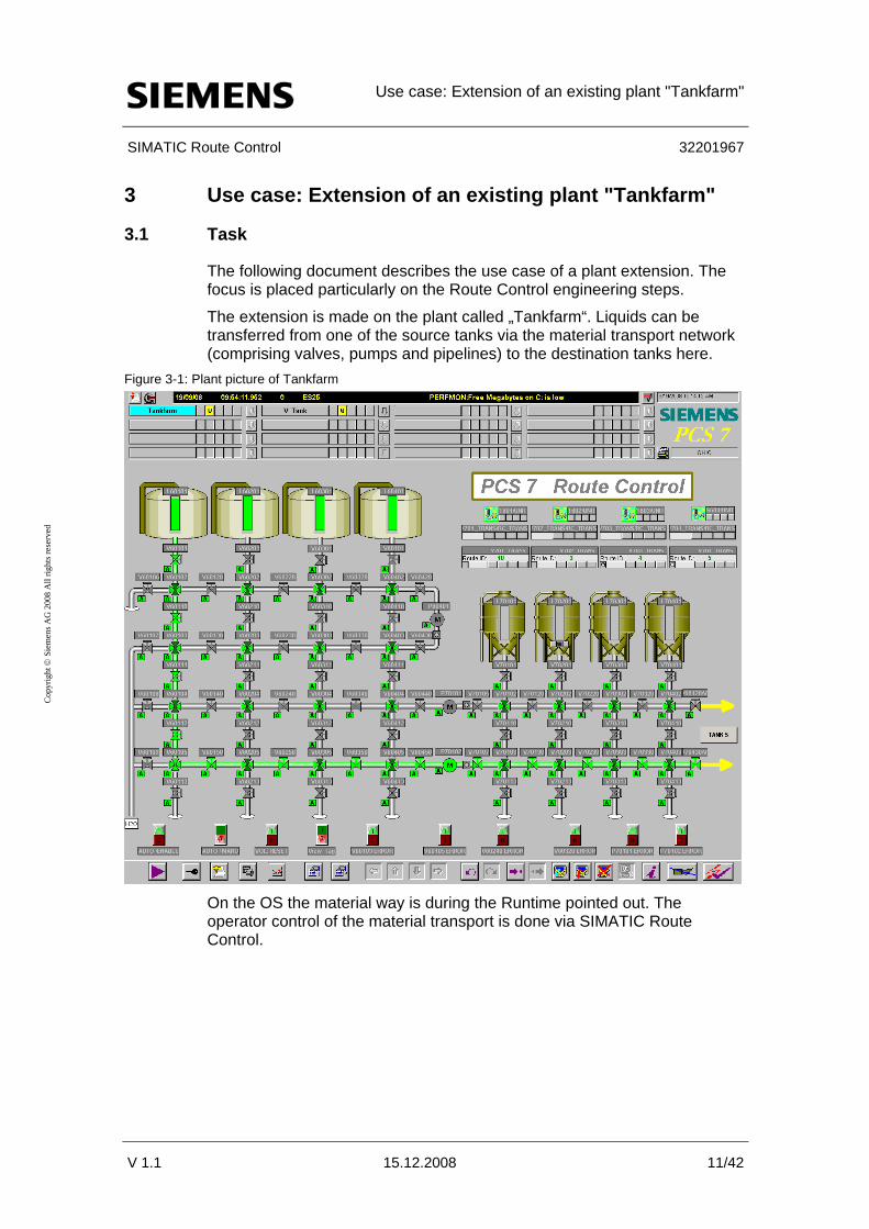
The following document describes the use case of a plant extension. The focus is placed particularly on the Route Control engineering steps.
The extension is made on the plant called „Tankfarm“. Liquids can be transferred from one of the source tanks via the material transport network (comprising valves, pumps and pipelines) to the destination tanks here.
Figure 3-1: Plant picture of Tankfarm
On the OS the material way is during the Runtime pointed out. The operator control of the material transport is done via SIMATIC Route Control.

Use case: Extension of an existing plant "Tankfarm"
SIMATIC Route Control 32201967
V 1.1 15.12.2008 12/42
Cop
yrig
ht ©
Sie
men
s AG
200
8 A
ll rig
hts r
eser
ved
The plant is to be extended by another destination tank and by the respective control, sensor and link elements required for the transport network.
Figure 3-2: Plant extension with destination tank and transport network
The necessary steps are configured both in SIMATIC Manager and in SIMATIC Route Control Engineering.

Use case: Extension of an existing plant "Tankfarm"
SIMATIC Route Control 32201967
V 1.1 15.12.2008 13/42
Cop
yrig
ht ©
Sie
men
s AG
200
8 A
ll rig
hts r
eser
ved
3.2 Engineering
The engineering of the extension takes few steps in SIMATIC Manager and SIMATIC Route Control Engineering.
As the work environment is already known through the process control system, working and navigating in Route Control will be very easy for the experienced user of SIMATIC PCS 7.
Prefabricated templates will help to realize the charts for valves and material transport quite easily which allows you to do the configuration fast and flexibly.
Procedures for plant extension The central engineering is done in SIMATIC Manager:
• Plant Hierarchy
– Appending the plant
– Appending the locations
• CFC
– Appending charts with interface blocks
– Appending transport blocks
The other tools of SIMATIC Route Control are started from the SIMATIC Manager menu:
• RC Wizard
– Applying the configured RC blocks to the CFCs and the locations to RC Engineering
– Assigning the IDs for the RC blocks
• RC Engineering
– Appending partial routes and assigning elements
– Loading and updating the changes on the RC Server

Use case: Extension of an existing plant "Tankfarm"
SIMATIC Route Control 32201967
V 1.1 15.12.2008 14/42
Cop
yrig
ht ©
Sie
men
s AG
200
8 A
ll rig
hts r
eser
ved
3.2.1 Extending the unit
Extending the Plant Hierarchy According to the desired plant extension the existing Plant Hierarchy (PH) has to be extended by a hierarchy folder.
The unit folder V705 is added to the plant folder V_Tank. Table 3-1: PH extension
Activity Screenshot 1. Insert a new folder via the
context menu of the plant folder: „Insert New Object > Hierarchy folder“ The folder will be renamed “V705” in this example.
2. In Properties of the new PH
folder the object type „Unit” is selected on the drop-down list on the tab “S88 Type Definition”. Click “OK” to apply the setting.

Use case: Extension of an existing plant "Tankfarm"
SIMATIC Route Control 32201967
V 1.1 15.12.2008 15/42
Cop
yrig
ht ©
Sie
men
s AG
200
8 A
ll rig
hts r
eser
ved
Plant picture extension In order to avoid that the plant picture becomes confusing later, a picture of the unit will be created in addition for the OS.
Table 3-2: PH extension
Activity Screenshot 1. Insert a new picture via the
context menu of the unit folder „V705“: „Insert New Object > Picture“
2. In order to have available the
block icons from the PH in the OS project later, select “Derive the block icons from the plant hierarchy” on the "Block icons" tab. Click “OK” to activate the selection.

Use case: Extension of an existing plant "Tankfarm"
SIMATIC Route Control 32201967
V 1.1 15.12.2008 16/42
Cop
yrig
ht ©
Sie
men
s AG
200
8 A
ll rig
hts r
eser
ved
Inserting the locations Locations are configured as equipment properties and are used to create partial routes. By connecting two locations a partial route is built. The locations are created in SIMATIC Manager as equipment properties in the PH of the S7 project.
Table 3-3: Configuring equipment properties in the PH
Activity Screenshot 1. New location types must be
created on a global level according to the planned partial route network. For this purpose go to the context menu of the PH folder “Equipment Properties” under “Shared Declarations” and select the menu option: „Insert New Object > Equipment Property“
2. This newly created location type
has to be processed. Assign the name in Properties, here „VTANK" and in addition select the option "Data type > LOCATION" from the drop-down list. For the destination tank tick the „Dest” box. Note that the „Source“, „Dest“ and „Via“ boxes should only be selected if this corresponds to the usage of the location type! Confirm the settings with “OK“.

Use case: Extension of an existing plant "Tankfarm"
SIMATIC Route Control 32201967
V 1.1 15.12.2008 17/42
Cop
yrig
ht ©
Sie
men
s AG
200
8 A
ll rig
hts r
eser
ved
Activity Screenshot 3. Four more location types must
be created for the planned plant extension. Create the „Equipment Properties“ „V705HA, V705VA, V705HB and V705VB“ analogously to the previous steps 4-5. None of the option boxes mentioned in step 2 will be ticked for these four location types.
4. The location for the new
destination tank must be inserted locally in the unit folder „V705“. For this purpose make the following selection via the context menu: „Insert New Object > Equipment Properties“ Assign the name “V705” also here.
5. This new location must be
assigned the location type „VTANK“ which has been created globally before. For this purpose open the context menu and insert an "Equipment Property": „Insert New Object > Equipment Property“

Use case: Extension of an existing plant "Tankfarm"
SIMATIC Route Control 32201967
V 1.1 15.12.2008 18/42
Cop
yrig
ht ©
Sie
men
s AG
200
8 A
ll rig
hts r
eser
ved
Activity Screenshot 6. The newly created location type
is selected from the drop-down list in the properties of the location now. Click “OK” to activate the selection.

Use case: Extension of an existing plant "Tankfarm"
SIMATIC Route Control 32201967
V 1.1 15.12.2008 19/42
Cop
yrig
ht ©
Sie
men
s AG
200
8 A
ll rig
hts r
eser
ved
Enumerations Due to the additional destination tank V705 another destination must be defined in “Enumerations”.
Table 3-4: Enumeration
Activity Screenshot 1. Create a new enumeration object
for the destination tank “V705” via the context menu of the enumeration “Destination”: „Insert New Object > Value“
2. Enter the value which you get
from the properties of the location "VTANK“ in the properties now. Click “OK” to apply the value.

Use case: Extension of an existing plant "Tankfarm"
SIMATIC Route Control 32201967
V 1.1 15.12.2008 20/42
Cop
yrig
ht ©
Sie
men
s AG
200
8 A
ll rig
hts r
eser
ved
3.2.2 Duplicating CFCs
CFCs required for the extension The additional valves and the fill level sensor of the plant extension must be created in the PH folder V705. The required charts V705, V70501, V70502, V70503, V70504, V70506, V70507, V70510, V70513 and L70501 are created analogously to the other unit blocks.
Table 3-5: CFC configuration
Activity Screenshot 1. From the PH folder “V704” copy
the corresponding CFCs of the elements (V70401,...) to the PH folder "V705".
2. Rename the CFCs according to
the unit ID.
3. After all required control and
sensor elements have been duplicated, the view shown on the right is obtained in the PH folder “V705”.
Note The valves V70405 and V70407 in the PH folder V704 must be renamed to V70420 and V70430, respectively, due to the plant change. The valves V70404 and V70406 can be deleted from the folder as they were added to the plant extension (V705) (V70504 and V70506).

Use case: Extension of an existing plant "Tankfarm"
SIMATIC Route Control 32201967
V 1.1 15.12.2008 21/42
Cop
yrig
ht ©
Sie
men
s AG
200
8 A
ll rig
hts r
eser
ved
Engineering the material transfer From the RC view no other SFC typical (from RC library) needs to be created for the automatic mode. The material transfer can be executed with the existing SFCs already. But due to the consistency of the configuration another SFC typical instance will be created for the newly created unit. In addition the link elements (LE) per partial route must be added in SIMATIC Manager to achieve material compatibility. Link elements store the information what material is actually on a partial route.
Table 3-6: Configurations for material transfer
Activity Screenshot 1. Enter a new PH folder via the
context menu of the unit folder “V705”: „Insert New Object > Hierarchy folder“ The folder gets the name “Transfer”.
2. To facilitate the material transfer
to the destination tank, copy the SFC „V704_TRANS” from the PH folder “V704 – Transfer” and paste it to the PH folder “V705 – Transfer”. Rename the SFC duplicate to "V705_TRANS".
3. To configure the link elements,
open the CFC “Material” in the PH folder “RCS”.

Use case: Extension of an existing plant "Tankfarm"
SIMATIC Route Control 32201967
V 1.1 15.12.2008 22/42
Cop
yrig
ht ©
Sie
men
s AG
200
8 A
ll rig
hts r
eser
ved
Activity Screenshot 4. Insert the block „RC_IF_LE“
(FB828) for each of the locations V705VA, ..., V705HB into the CFC. Rename the blocks according to the locations.
Note For more information about the configuration of valves, motors, sensors and the special Route Control blocks (RC_IF_ROUTE, RC_IF_VALVE,...) refer to the manual “SIMATIC Route Control > Configuring in SIMATIC Manager”
http://support.automation.siemens.com/WW/view/en/27002783
and to the manual „Getting Started Route Control > Route Control Configuration in the Automation System”
http://support.automation.siemens.com/WW/view/en/27002720

Use case: Extension of an existing plant "Tankfarm"
SIMATIC Route Control 32201967
V 1.1 15.12.2008 23/42
Cop
yrig
ht ©
Sie
men
s AG
200
8 A
ll rig
hts r
eser
ved
3.2.3 Project data import with the RC Wizard
The Route Control Wizard facilitates the transfer of RC-relevant data from SIMATIC Manager to Route Control Engineering.
In addition the Route Control Wizard assigns the IDs for the transport route elements and links. They are inserted by it automatically at the RC blocks in the respective CFCs.
Table 3-7: Configurations for material transfer
Activity Screenshot 1. Start the RC Wizard from
SIMATIC Manager via the menu option: “Options > SIMATIC Route Control > Follow the instructions. Data synchronization is sufficient for the modifications which were made.
2. Finally you can check the result
of the data transfer in the “Wizard Log”. Note the instructions with regard to compilation and download of the CFC modifications, compilation of OS and download und updating of the Route Control Server.
Note For more information about the Route Control Wizard and its execution refer to the manual “Getting Started Route Control > Route Control Wizard”
http://support.automation.siemens.com/WW/view/en/27002720

Use case: Extension of an existing plant "Tankfarm"
SIMATIC Route Control 32201967
V 1.1 15.12.2008 24/42
Cop
yrig
ht ©
Sie
men
s AG
200
8 A
ll rig
hts r
eser
ved
3.2.4 Loading the project modifications
Automation System Following the engineering of the CFCs and the data import through the RC Wizard the project modifications must be made known to the automation system.
Compile and download the S7 user program into the automation system. Proceed as usual but note the selected options and change them if necessary.
For transferring the configuration modifications made it is sufficient to perform a delta download. A CPU stop of the AS is not necessary here. Modifications can be entered „online“.
In the case of an entire download of an AS make sure that all routes in which the AS is involved are deactivated.
Operator Station After the S7 program has been downloaded to the automation system, the Operator Station must get the new data as well.
The OS compilation is performed from out of the SIMATIC Manager. Proceed as usual but note the selected options and change them if necessary.
Note For information about delta download/entire download refer to the manual "Engineering System > Compiling and downloading"
http://support.automation.siemens.com/WW/view/en/27002802
and to the manual „Operator Station > Downloading and Activating a Project”
http://support.automation.siemens.com/WW/view/en/27002758

Use case: Extension of an existing plant "Tankfarm"
SIMATIC Route Control 32201967
V 1.1 15.12.2008 25/42
Cop
yrig
ht ©
Sie
men
s AG
200
8 A
ll rig
hts r
eser
ved
3.2.5 Configuring in RC Engineering
In Route Control Engineering mode tables, partial routes and materials/material successors are configured.
The imported data of the RC Wizard from the S7 project are used in Route Control Engineering to implement the plant extension.
Mode table in RC Engineering Mode tables contain all partial routes which exist in the material transport network. Each partial route is assigned to a mode table.
To be complete the existing mode table must be extended by the new partial routes.
Partial routes in RC Engineering Partial routes are the smallest sections of a route network (e.g. pipelines) in the sense of route control. The task of the route control is to set routes and transport materials on them. The partial routes get elements assigned to them.
A total route request is calculated via the RC Server in runtime. The RC Server uses an algorithm for this to find the shortest possible route through the plant network. The configured partial routes are combined with each other in a suitable way for this.

Use case: Extension of an existing plant "Tankfarm"
SIMATIC Route Control 32201967
V 1.1 15.12.2008 26/42
Cop
yrig
ht ©
Sie
men
s AG
200
8 A
ll rig
hts r
eser
ved
Extending the mode table by new partial routes Table 3-8: Creating new partial routes
Activity Screenshot 1. In Route Control Engineering the
material transport routes must be configured with the respective elements.
2. To add a new partial route, go to
the context menu of the mode table and select the menu option: “Add partial route”
3. At „Name“ enter the name of the
partial route. From the drop-down lists of source and destination select the required location of the partial route. Click “OK” to apply your settings.

Use case: Extension of an existing plant "Tankfarm"
SIMATIC Route Control 32201967
V 1.1 15.12.2008 27/42
Cop
yrig
ht ©
Sie
men
s AG
200
8 A
ll rig
hts r
eser
ved
Activity Screenshot 4. After the partial routes have been
defined, route elements (valves, sensors,…) are assigned to every partial route.
5. For this purpose select a partial
route from the mode table. Use drag & drop to drag the respective element from one of the “… elements” folders to the list of the “Elements” tab of the partial route.
6. A window opens automatically
where you have to enter the mode level for controlling the element. You can revise them later, if necessary, via the "Modes" tab. To configure the elements on the partial routes proceed according to the following control tables.

Use case: Extension of an existing plant "Tankfarm"
SIMATIC Route Control 32201967
V 1.1 15.12.2008 28/42
Cop
yrig
ht ©
Sie
men
s AG
200
8 A
ll rig
hts r
eser
ved
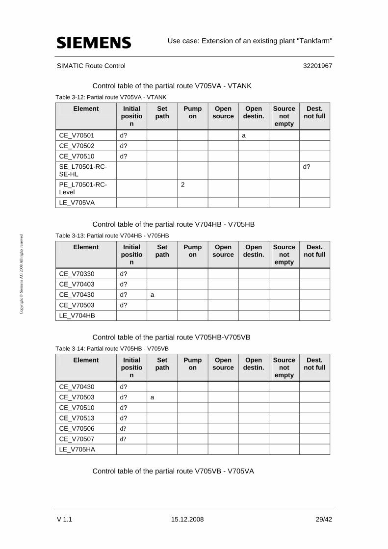
Control tables The following control tables contain all route elements of the partial route which must be configured. The elements shall be controlled in the individual mode levels as shown in the following tables.
The symbols which are contained in the control tables are defined as follows: Table 3-9
Symbol Description
a Activation d Deactivation ? Check a? Check for activation d? Check for deactivation 2 Delay time Off
Required partial routes Control table of the partial route V704HA-V705HA
Table 3-10: Partial route V704HA - V705HA
Element Initial positio
n
Set path
Pump on
Open source
Open destin.
n
Source not
empty
Dest. not full
CE_V70320 d? CE_V70402 d? CE_V70420 d? a CE_V70502 d? LE_V704HA
Control table of the partial route V705HA-V705VA Table 3-11: Partial route V705HA - V705VA
Element Initial positio
n
Set path
Pump on
Open source
Open destin.
Source not
empty
Dest. not full
CE_V70420 d? CE_V70501 d? CE_V70502 d? a CE_V70510 d? CE_V70504 d? CE_V70505 d? LE_V705HA
Use case: Extension of an existing plant "Tankfarm"
SIMATIC Route Control 32201967
V 1.1 15.12.2008 29/42
Cop
yrig
ht ©
Sie
men
s AG
200
8 A
ll rig
hts r
eser
ved
Control table of the partial route V705VA - VTANK Table 3-12: Partial route V705VA - VTANK
Element Initial positio
n
Set path
Pump on
Open source
Open destin.
Source not
empty
Dest. not full
CE_V70501 d? a CE_V70502 d? CE_V70510 d? SE_L70501-RC-SE-HL
d?
PE_L70501-RC-Level
2
LE_V705VA
Control table of the partial route V704HB - V705HB Table 3-13: Partial route V704HB - V705HB
Element Initial positio
n
Set path
Pump on
Open source
Open destin.
Source not
empty
Dest. not full
CE_V70330 d? CE_V70403 d? CE_V70430 d? a CE_V70503 d? LE_V704HB
Control table of the partial route V705HB-V705VB Table 3-14: Partial route V705HB - V705VB
Element Initial positio
n
Set path
Pump on
Open source
Open destin.
Source not
empty
Dest. not full
CE_V70430 d? CE_V70503 d? a CE_V70510 d? CE_V70513 d? CE_V70506 d? CE_V70507 d? LE_V705HA
Control table of the partial route V705VB - V705VA

Use case: Extension of an existing plant "Tankfarm"
SIMATIC Route Control 32201967
V 1.1 15.12.2008 30/42
Cop
yrig
ht ©
Sie
men
s AG
200
8 A
ll rig
hts r
eser
ved
Table 3-15: Partial route V705VB - V705VA
Element Initial positio
n
Set path
Pump on
Open source
Open destin.
Source not
empty
Dest. not full
CE_V70501 d? CE_V70502 d? a CE_V70503 d? CE_V70510 d? a LE_V705VB
Loading and updating the Route Control Server The Route Control Server determines a suitable path from source to destination based on the configured partial routes and loads this information to the automation system.
Start the runtime of the OS project beforehand. Table 3-16: Creating new partial routes
Activity Screenshot 1. Start the server via the start
menu: "Start > SIMATIC > Route Control > Server" The server is shown as an icon in the task bar now.
2. Go to RC Engineering and select the menu option: "Options > Download to server" Then click the “Start” button.
3. Open the RC Center via the start
menu: "Start > SIMATIC > Route Control > Center" From the menu bar select the icon “Show server status".

Use case: Extension of an existing plant "Tankfarm"
SIMATIC Route Control 32201967
V 1.1 15.12.2008 31/42
Cop
yrig
ht ©
Sie
men
s AG
200
8 A
ll rig
hts r
eser
ved
Activity Screenshot 4. Click “Update” to transfer the
new RC project data to the RC Server.
5. The RC Server has been loaded and updated with the new project data now. Push “Close” to close the window while the RC Server process continues in the background.

Use case: Extension of an existing plant "Tankfarm"
SIMATIC Route Control 32201967
V 1.1 15.12.2008 32/42
Cop
yrig
ht ©
Sie
men
s AG
200
8 A
ll rig
hts r
eser
ved
3.3 Materials in RC Engineering
Certain materials must not follow each other or be transported on the same route in many parts of industry. Therefore route control provides the option to engineer material compatibility (material successors). The information what material is being transferred along what partial route is temporarily stored during runtime in a link element (LE) which is interconnected on the partial route. With this information the route control checks whether or not the partial route may be used for the next material transport with the next material (interlocking by means of material).
Figure 3-3: Engineering material compatibility in RC Engineering
Note For more information about Route Control Engineering and the engineering of material successors refer to the manual “Getting Started Route Control > Materials and material successors”
http://support.automation.siemens.com/WW/view/en/27002720

Use case: Extension of an existing plant "Tankfarm"
SIMATIC Route Control 32201967
V 1.1 15.12.2008 33/42
Cop
yrig
ht ©
Sie
men
s AG
200
8 A
ll rig
hts r
eser
ved
3.4 System management
With regard to material transport the OS provides several options of starting or controlling a route. The material transport can be routed via the RC faceplate, the SFC faceplate or the RC Center.
Figure 3-4: Runtime view of the plant extension with SFC faceplate opened

Use case: Extension of an existing plant "Tankfarm"
SIMATIC Route Control 32201967
V 1.1 15.12.2008 34/42
Cop
yrig
ht ©
Sie
men
s AG
200
8 A
ll rig
hts r
eser
ved
SFC faceplate With a sequential control which is created in SFC Editor both discontinuous and continuous modes of operating plants can be implemented. The SFC faceplate permits to trigger and/or interrupt this sequential control in WinCC Runtime.
Figure 3-5: SFC dialog for transport route control
The locations which have been configured before can be displayed in the lower drop-down lists to be considered for the route selection. The settings tell the system what source tank is emptied, what destination tank is filled and via what pump the material flow shall take place.
The material transport is controlled via the buttons. Switching from manual operation to automatic mode is also possible.

Use case: Extension of an existing plant "Tankfarm"
SIMATIC Route Control 32201967
V 1.1 15.12.2008 35/42
Cop
yrig
ht ©
Sie
men
s AG
200
8 A
ll rig
hts r
eser
ved
RC Center The RC Center provides information about the transport route and the route elements contained in it and about control options.
In addition the RC Server can be selected and updated from here. Figure 3-6: Route Control Center
The upper part of the RCC window shows the information about a route. The lower part shows the respective route elements.
In addition three tabs can be selected in the lower part:
• “Functions” tab
Displays the element control in the different mode levels.
• “Elements” tab
Displays the setpoint and actual positions of the respective elements.
• “Partial routes” tab
Displays all partial routes of a route.

Use case: Extension of an existing plant "Tankfarm"
SIMATIC Route Control 32201967
V 1.1 15.12.2008 36/42
Cop
yrig
ht ©
Sie
men
s AG
200
8 A
ll rig
hts r
eser
ved
RC faceplate The RC faceplate facilitates the control of the transport routes as well.
Figure 3-7
In the manual mode there is the option to request, start, stop, finish and continue a route.
The overview shows the source and destination locations and the intermediate locations through which the material transport is executed. However these locations cannot be changed in the RC faceplate.
The mode levels displayed in the lower part tell whether the mode fulfils the defined behaviour.
Note For more information about the RC faceplate and its display and control elements refer to the manual “SIMATIC Route Control > Operator Control and Monitoring”
http://support.automation.siemens.com/WW/view/en/27002783

Use case: Extension of an existing plant "Tankfarm"
SIMATIC Route Control 32201967
V 1.1 15.12.2008 37/42
Cop
yrig
ht ©
Sie
men
s AG
200
8 A
ll rig
hts r
eser
ved
Overview Tankfarm
Figure 3-8: Runtime view of the Tankfarm plant
The entire plant should be in automatic mode. Thus the RC will open or activate the elements required for route selection, such as valves and motors, as soon as this is required. For this purpose the automatic mode switch must be set to “Auto”.

Benefits
SIMATIC Route Control 32201967
V 1.1 15.12.2008 38/42
Cop
yrig
ht ©
Sie
men
s AG
200
8 A
ll rig
hts r
eser
ved
4 Benefits
4.1.1 Engineering
SIMATIC Route Control is fully integrated in SIMATIC PCS 7 and can be adapted easily to the existing plant size.
The possibility of using templates of model charts (CFC) and model blocks (SFC) saves time needed for creating customized charts and blocks and helps avoiding engineering errors. Thus control and sensor elements can be added fast.
The engineering costs can be cut through simplified modelling and engineering as the unit can be mapped directly to the Plant Hierarchy, locations and partial routes.
4.1.2 Operation/maintenance
The operator can continuously monitor the operation thanks to the operation and monitoring supports provided by SFC, RC Center and the RC faceplate and quickly and safely respond and manipulate the process if required.
If maintenance must be carried out, all running route transfers will be finished and at the same time the start of new material transfers will be halted until the maintenance is completed.
4.1.3 User of the system
The specific requirements for the plant extension can be integrated into the existing project fast and clearly.
Engineering changes can be applied “online”, i.e. during runtime without having to stop the process ("delta download”).

Appendix and List of Further Literature
SIMATIC Route Control 32201967
V 1.1 15.12.2008 39/42
Cop
yrig
ht ©
Sie
men
s AG
200
8 A
ll rig
hts r
eser
ved
5 Appendix and List of Further Literature
5.1 Glossary
Location (also node) Locations are the start, intermediate (via) and end locations of partial routes or routes. Each location is an instance of a location type. Locations are configured in SIMATIC Manager as equipment properties of units and imported to Route Control Engineering for the creation of partial routes.
Element Interface block from the Route Control library for the connection of process blocks. The names of these interface blocks start with RC_IF_. In Route Control Engineering elements are inserted in partial routes. Here it is configured how the element is controlled in the various mode levels.
Equipment Properties The TH folder "Equipment Properties" in "Global Declarations" of the PCS 7-Projekts contains all node-types.
All nodes will engineered as "Equipment Property" in the respective unit of the SIMATIC Manager.
Mode table A mode table comprises up to 32 modes or mode levels grouping levels which belong together under a process point of view.
Example: Brewery / brewing room (mode table)
• Initial position (mode level)
• Open transport valves (mode level)
• Switch on pump (mode level)
• Open source valve (mode level)
Model levels The elements of a route or partial route need not be activated or deactivated all together but they can be installed in up to 32 groups, the so-called mode levels, and controlled differently.
It is the responsibility of the user program to link the individual mode levels in a suitable way.
Examples:
• If “initial position is reached”,
• then “open transport valves”
• if “transport valves are open”

Appendix and List of Further Literature
SIMATIC Route Control 32201967
V 1.1 15.12.2008 40/42
Cop
yrig
ht ©
Sie
men
s AG
200
8 A
ll rig
hts r
eser
ved
• then “switch on pump”
“Initial position is reached” means in this case that the output parameter value QMODE of RC_IF_ROUTE linked with the bit of the mode level via an “OR” must be 1.
“Open transport valves” means that the bit of the mode level for the input parameter MODE at RC_IF_ROUTE must be set to 1.
Location Location
Material compatibility The pipelines of industrial plants may be used for transporting different materials. Since these materials show various degrees of compatibility among each other, material successors are determined in RC to ensure material compatibility.
RC Route Control
Sensor element A sensor element SE is an object which feeds back a value from the process and indicates whether an expected actual value corresponds to the current actual value. SEs are not controlled.
Example: Limit switch, flow meter,…
Server (here Route Control Server)
Own computer or also redundant computer pair for the processing of route queries from the Route Control automation systems and as a link between these and the clients (Route Control Center).
SFC SFC stands for “Sequential Function Chart” (sequential control).
Typical applications of sequential control systems involve processes and plants with discontinuous characteristics. Sequential control can also be used for continuous processes and plants, for example, for approaching and withdrawing movements, operating point changes, and state changes due to faults.
Control element A control element (CE) is an object which can be controlled and which can also feed back a value.
Example: Motor, valve,…

Appendix and List of Further Literature
SIMATIC Route Control 32201967
V 1.1 15.12.2008 41/42
Cop
yrig
ht ©
Sie
men
s AG
200
8 A
ll rig
hts r
eser
ved
Partial route Partial routes are the individual sections of a route. They are defined by the source and destination locations. When partial routes are engineered elements are inserted in them. All partial routes together form the route network from which the search algorithm selects certain partial routes and combines them to form routes.
Link element A link element (LE) is an object which represents a material in a transport medium, e.g. pipeline or conveyor belt.
Route A route always consists of 1 to n partial routes. The partial routes are selected during runtime. The route comprises all elements which are used on its partial routes and it stretches from the source to the destination of the material transport. In Route Control engineering only partial routes are configured. A total route is generated during runtime only when a route is requested stretching from the source to the destination of the material transport.
Route element A route element can be, for instance, control, sensor, link or parameter elements which are part of a partial route.

Appendix and List of Further Literature
SIMATIC Route Control 32201967
V 1.1 15.12.2008 42/42
Cop
yrig
ht ©
Sie
men
s AG
200
8 A
ll rig
hts r
eser
ved
5.2 Literature
Bibliographic references Table 5-1
Topic Title /1/ Route Control Prozessleitsystem PCS 7 Route Control V7.0 SP1 /2/ Route Control Prozessleitsystem PCS 7 V7.0.1 Getting Started
Route Control
Internet links Table 5-2
Topic Title /1/ Siemens A&D
Customer Support
http://support.automation.siemens.com