application of barrier membrane technology to catalytic
TRANSCRIPT

Application of Barrier Membrane Technology to CatalyticCracker Recycle Gas Hydrogen Separations
L. D. Trowbridge
Oak Ridge National Laboratoryph. (865) 576-2496,fax (865) 574-6872,e-mail: Idt @ ornl.gov
Inorganic Membrane Technology Laboratory(IMTL, Bechtel-Jacobs LLC, Oak Ridge, TN)
Phillips PetroleumChevronTexaco
.Oak Ridge National LaboratoryU. S. Department of Energy
Background
0 Refineries use many high pressure hydrogenation processes
0 - 20% of the hydrogen used is purged (ultimately used as fuel)
l Recycle, purification and reuse will conserve hydrogen (and $$)
l Inorganic membranes offer the possibility of- Corrosion resistance (custom materials)- Higher operating temperatures, pressures and throughput
l Separation performed at temperatures and pressures closer toprocess conditions offers considerable savings
Oak Ridge National LaboratoryU. S. Department of Energy

History
l Inorganic membranes have been used by the US Government forgas separation (uranium isotopes) on a vast scale for over 50 years
l Inorganic membranes designed for H, / HC separation are beingdeveloped by the Inorganic Membrane Technology Laboratory(IMTL) in Oak Ridge, TN.
l Commercialization of similar membranes for other applications isunderway via Pall Corp
l Successful application to petroleum refining is the question.
Oak Ridge National LaboratoryU. S. Department of Energy

Statement of Problem
l Determine the effectiveness of custom inorganic membranes forseparation of hydrogen from hydrocarbons in high pressure mixturessimulating refinery gas streams.
l Effectiveness encompasses a variety of performance factorsb Separation efficiencyb Throughputb Optimum temperatures and pressuresb Allowable temperatures and pressuresb Longevity in process environment
0 This project was funded in early June 2001
Oak Ridge National LaboratoryU. S. Department of Energy

Accomplishment - Summary
Completed construction and testing of separation apparatus
0 Initial testing is on an IMTL Knudsen membrane
0 Separaticy testing
b Physical Property Ranges examined so far:- Temperature: 23 to 140°C- Pressures: 1 to 8 atm
Flows: up to 100 seem / cm*
b Binary gas mixtures examined:H, I CH, He/CO,H2 / C2t-b He/ArH2 / W8
b Data Analysis: Comparison of observed to ideal separation factorsafter correcting for known effects (back pressure; cut; mixing)
Oak Ridge National LaboratoryU. S. Department of Energy
5

Apparatus Schematic
heater
SourceGas
Mixture
Oak Ridge National LaboratoryU. S. Department of Energy
Hoodexhaust
Color Codes
HP/HC mixture
Nitrogen
~ i,*. .,,dUrrL ,,,,,-,-.\jj sillvs?,m Bypass/purge line
6
80%
60%
20%
0%
._._- ___- _.
II
_ - _ _ _-1 -
II
___._.-.- ___
II
l
23C
0 2 4 6 8
Average P [atm]
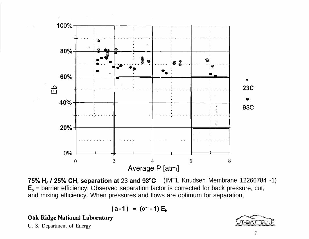
75% H, / 25% CH, separation at 23 and 93OC (IMTL Knudsen Membrane 12266784 -1)E, = barrier efficiency: Observed separation factor is corrected for back pressure, cut,and mixing efficiency. When pressures and flows are optimum for separation,
(a -1 ) = (a*-I)EbOak Ridge National LaboratoryU. S. Department of Energy
7

80%
------a------
24C
0 2 4 6 ‘8Average P [atm]
75% H, / 25% C,H, separation at 24 to 133OC (IMTL Knudsen Membrane 1226678-1-l)E, = barrier efficiency: Observed separation factor is corrected for back pressure, cut,and mixing efficiency. When pressures and flows are optimum for separation,
( a - l ) = (a*-l)Eb
Oak Ridge National LaboratoryU. S. Department of Energy
8

I I II I --i-- 0
nl-
I

._ _ . .._. /- _ _ _II .-.A_...
Observations(Knudsen Membrane)
Most gas mixtures behaved similarly, as expected for a Knudsenmembrane.
The typical mixtures showed efficiencies of 80%+ at lower pressures(trending higher as pressures decrease). Efficiencies declined to70% or lower at higher pressures.
Separation factors for mixtures with more condensable gases (i.e.,CO, and C,H,) were measurably lower, especially at lowtemperatures, suggesting enhanced surface flow of the heaviercompound.
Oak Ridge National LaboratoryU. S. Department of Energy

FY2002Planned Work
Complete remaining separation tests using Knudsen membrane(higher temperature; > 200°C )
Obtain and install surface flow membrane; determine separationfactors for binary hydrogen hydrocarbon gas mixtures
Performance testing on promising additional membrane designs
Adapt apparatus for multi-component feed gas separation testing
FY2003
l Obtain lab-scale micro-catalytic bed unit (or fluid catalytic crackingunit or hydrotreater) from industrial partner.
l Performance testing using simulated cat-cracker recycle gas usingmost promising membrane
Oak Ridge National LaboratoryU. S. Department of Energy

A Word on Membrane Designs
l Knudsen membrane - Effusive (molecular) gas flowb H, separates to low pressure side of membraneb Best performance at higher temperatures
l Surface Flow - small pores size and surface composition encouragesome species to adsorb and transport by surface flow.b Heavier components preferentially adsorbb Each compound is likely to have an optimum temperatureb Increased surface flow must overcome higher H, effusive flowb lf if does then H, will separate to high pressure side of membrane
l Sieve - pores physically screen larger molecules.b Potential for very high separation factorsb Potential for high temperature operationb H, preferentially separates to low pressure side of membrane
Oak Ridge National LaboratoryU. S. Department of Energy

0
Conclusions
The separation apparatus has proven capable of determiningseparation efficiency with reasonable accuracy for the relatively lowseparation factors that a Knudsen membrane
0 It should thus have no difficulty with the higher separation factorsanticipated for surface flow or sieve membrane designs
Oak Ridge National LaboratoryU. S. Department of Energy

Participants
ORNLUnivTotal DOE
Industry (in kind)
Funding Table
FY2001 FY2002(actual) ml J
120k 290k
120k 290k
20k 75k
Oak Ridge National LaboratoryU. S. Department of Energy
FY2003(w)
300k
300k
75k

BACKUP SLIDES
Oak Ridge National LaboratoryU. S. Department of Energy
B9
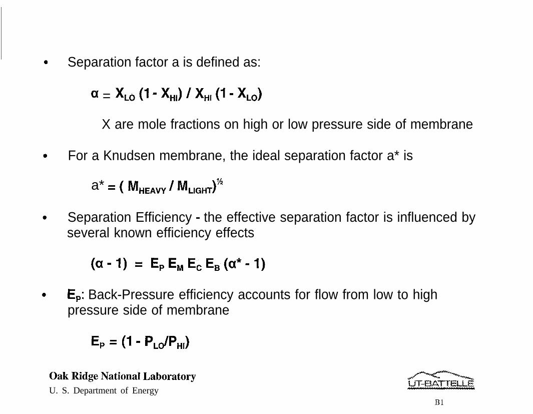
Separation factor a is defined as:
a = XL, (1 - X”,) / XH, (1 - XL,)
X are mole fractions on high or low pressure side of membrane
For a Knudsen membrane, the ideal separation factor a* is
a* = (M /M 1-??
HEAVY LIGHT
Separation Efficiency - the effective separation factor is influenced byseveral known efficiency effects
(a-l) = EpENIECEB(a*-1)
E,: Back-Pressure efficiency accounts for flow from low to highpressure side of membrane
E, = (I - P,dPH,)
Oak Ridge National LaboratoryU. S. Department of Energy
Bl

l E,, Mixing Efficiency, accounts for depletion of the separatedcomponent at tube wall. For “well developed” flow in a tube,
E,=exp -[ (2/f) (q/Dp) (v/V) ]
D = diffusivity v = radial bulk gas velocityn = viscosity , V = axial bulk gas velocityp = density f = friction factor
0 E,, Cut Correction, accounts for depletion of separated componentalong axis of the tube
Ec = 118 In [i/(1- e)]
6 = Flow(L0) / Flow(lN)
0 E,, Barrier efficiency, is the efficiency of the membrane relative toan ideal Knudsen membrane. At the limit of P,* = 0 and 8 = 0 ,
E, = (a - l)/(a* - 1)
Oak Ridge National LaboratoryU. S. Department of Energy
B2

I
23C
4 6 8Average P [atm]
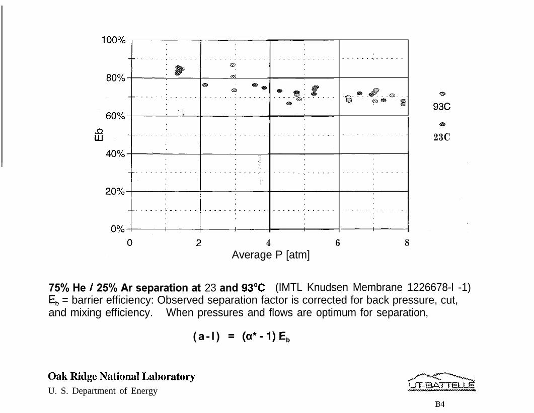
75% He / 25% Ar separation at 23 and 93OC (IMTL Knudsen Membrane 1226678-l -1)E, = barrier efficiency: Observed separation factor is corrected for back pressure, cut,and mixing efficiency. When pressures and flows are optimum for separation,
( a - l ) = (a*-I)E,,
Oak Ridge National LaboratoryU. S. Department of Energy
B4

1 +
0 2 4 6 8
ideal
0
23C
Average P [atm]
75% H, / 25% CH4 separation at 23 and 93OC (IMTL Knudsen Membrane 1226678-l -1)Observed separation factor corrected for back pressure, cut, and mixing efficiency, ratioedto ideal separation factor, per
( a - l ) = (a*-l)E,EcE,E,
- acorrected is essentially the separation factor expected at optimum flows and pressures.
Oak Ridge National LaboratoryU. S. Department of Energy

-
4.5
4
g
1.5
1
ideal
24C
@D
9oc
133c
0 2 4 6 8Average P [atm]
75% H, / 25% C,H, separation at 23 to 133OC (IMTL Knudsen Membrane 1226678-l -1)Observed separation factor corrected for back pressure, cut, and mixing efficiency,ratioed to ideal separation factor, per
( a - l ) = (a*-l)E,E,E,E,
acorrected is essentially the separation factor expected at optimum flows and pressures.
Oak Ridge National LaboratoryU. S. Department of Energy

ideal
24C
4 6 8Average P [atm]
75% H, / 25% C,H, separation at 23 to 133OCObserved separation factor, a.
(IMTL Knudsen Membrane 1226678-1-I)No corrections have been applied for known effects of
back pressure, cut, or mixing efficiency.
Oak Ridge National LaboratoryU. S. Department of Energy
B7

Conclusions
0 Inorganic membranes have potential to allow gas separations withhigh separation factors, reasonable throughput, at high temperaturesand pressures.
0 Scaleup can be done (the historic example of gaseous diffusionillustrates this well beyond the scales needed in refining)
0 Spinoffs (beyond the targeted application) might include otherhydrogen separations (such as syn-gas applications) or other gasseparations (such as H2S).
0 The issue is one of demonstrating the promised effectiveness at labscale and then larger scales and determining economics
Oak Ridge National Laboratory .U. S. Department of Energy
B8
