application on drive technology
TRANSCRIPT

Application on Drive Technology
SIMATIC Easy Motion Control Parameterization Guide
Closed-Loop Controlled Positioning of an Axis with SIMATIC CPU 314C-2 DP, MICROMASTER and SIMATIC Easy Motion Control

Closed-Loop Controlled Positioning of an Axis with SIMATIC CPU 314C-2 DP, MICROMASTER and SIMATIC Easy Motion Control
Rev. A - final 24.06.2005 2/46
Cop
yrig
ht ©
Sie
men
s A
G 2
005
All
right
s re
serv
ed
2166
9390
_Ger
egel
tesP
osE
asyM
C_P
aram
etrie
rung
en_D
OK
U_v
10_e
.doc
Warranty, Liability and Support
We accept no liability for information contained in this document.
We do not accept liability, whatever the legal basis, for any damages arising from the use of examples, notes, programs, configuration and performance data etc. described in this document, except where we are obliged to by the German Product Liability Act or in cases of willful damage or gross negligence, injury to life, body or health, breach of guarantee for the condition of products or items assumed by us, fraudulent concealment of a defect or breach of a substantial contractual obligation. However, claims arising from a breach of a condition which goes to the root of the contract shall be limited to the foreseeable damage which is intrinsic to the contract, unless caused by intent or gross negligence or based on mandatory liability for injury of life, body or health. The above conditions are not meant to change the burden of proof to the detriment of the user.
The application examples do not purport to cover all details or variations in equipment, nor do they provide for every possible contingency. They are not customer-specific solutions. They are only intended to provide support for typical tasks. You are responsible for ensuring that the described products are used correctly. These application examples do not relieve you of the responsibility to use sound practices in application, installation, operation and maintenance. By using this application example you accept that Siemens is not liable for any damages except for those specified in the above liability clause. We reserve the right to make changes in these application examples at any time without prior notice. If there are any deviations between the recommendations provided in this application example and other Siemens publications – e.g. Catalogs – the contents of the other documents have priority.
Copyright© 2005 Siemens A&D. Any form of duplication or distribution of these application examples or excerpts hereof is prohibited without the expressed consent of Siemens Energy & Automation, Inc.
For questions about this document please use the following e-mail address:
mailto:[email protected]
XXXXXXX 5.12.2003

Closed-Loop Controlled Positioning of an Axis with SIMATIC CPU 314C-2 DP, MICROMASTER and SIMATIC Easy Motion Control
Rev. A - final 24.06.2005 3/46
Cop
yrig
ht ©
Sie
men
s A
G 2
005
All
right
s re
serv
ed
2166
9390
_Ger
egel
tesP
osE
asyM
C_P
aram
etrie
rung
en_D
OK
U_v
10_e
.doc
Foreword This document is an extension to the document entitled „Closed-Loop Controlled Positioning of an Axis with SIMATIC S7-300 CPU 314C-2 DP, MICROMASTER 440 and SIMATIC Easy Motion Control, Application Description“.
The Application Description contains commissioning instructions which are based on saved lists of parameters. This document, however, contains a step-by-step guide to assigning those parameters.
Structure of the document This document contains a step-by-step guide to the assignment of parameters to the following components:
• MICROMASTER 440
• CPU 414C- 2 DP
• SIMATIC Easy Motion Control
• SIMATIC NET OPC server
XXXXXXX 5.12.2003

Closed-Loop Controlled Positioning of an Axis with SIMATIC CPU 314C-2 DP, MICROMASTER and SIMATIC Easy Motion Control
Rev. A - final 24.06.2005 4/46
Cop
yrig
ht ©
Sie
men
s A
G 2
005
All
right
s re
serv
ed
2166
9390
_Ger
egel
tesP
osE
asyM
C_P
aram
etrie
rung
en_D
OK
U_v
10_e
.doc
Contents
1 Safety Instructions..................................................................................... 5 2 Application Description............................................................................. 5 3 Commissioning the MICROMASTER........................................................ 6 3.1 Preconditions for Configuring the MICROMASTER..................................... 7 3.2 Variants of the Starter Program ................................................................... 8 3.3 Create a Project with Starter (Stand-alone) ................................................. 9 3.4 Create/Select a Project with DriveES......................................................... 13 3.5 Parameterize the Motor Data ..................................................................... 16 3.6 Check the Encoder Connection ................................................................. 21 3.7 Optimize the Speed Controller ................................................................... 25 3.8 Close the Parameterization........................................................................ 26 3.9 Save the Parameterization......................................................................... 29 4 Parameterization of the CPU 314C-2 DP ................................................ 30 4.1 Parameterization of the Internal Counter ................................................... 30 4.2 Parameterization of the Analog Interface................................................... 31 5 Parameterization of the Motion Axis in Easy Motion Control .............. 32 5.1 Defining the Operating Parameters............................................................ 32 5.2 Parameterization of the Axis Parameters................................................... 33 5.3 Move the Axis during Commissioning ........................................................ 38 5.3.1 Wiring Test ................................................................................................. 38 5.3.2 Offset Compensation ................................................................................. 40 5.3.3 Closed-Loop Position Control Optimization ............................................... 41 6 Parameterization of the SIMATIC NET OPC Server .............................. 42 6.1 Test the OPC Configuration with OPC Scout............................................. 42 7 Internet Links............................................................................................ 45
XXXXXXX 5.12.2003

Closed-Loop Controlled Positioning of an Axis with SIMATIC CPU 314C-2 DP, MICROMASTER and SIMATIC Easy Motion Control
Rev. A - final 24.06.2005 5/46
Cop
yrig
ht ©
Sie
men
s A
G 2
005
All
right
s re
serv
ed
2166
9390
_Ger
egel
tesP
osE
asyM
C_P
aram
etrie
rung
en_D
OK
U_v
10_e
.doc
1 Safety Instructions
Risk of injury
Warning The hardware components used as components in plant and systems require compliance with special rules and regulations, depending on the area of application. Please comply with prevailing safety and accident-prevention regulations, e.g. IEC 204 (emergency STOP devices). Failure to comply with these regulations may lead to serious injury and to damage to machinery and equipment.
Danger Risk of injury caused by moving parts.
Danger You may come into contact with live cables. Therefore, you MUST isolate the power before wiring the application setup.
2 Application Description
This document is an extension to the document entitled „Closed-Loop Controlled Positioning of an Axis with SIMATIC S7-300 CPU 314C-2 DP, MICROMASTER 440 and SIMATIC Easy Motion Control, Application Description“.
The Application Description contains
• the fundamental principles of the technology used,
• a description of the components used,
• setup and commissioning instructions and
• operating instructions for the application.
XXXXXXX 5.12.2003

Closed-Loop Controlled Positioning of an Axis with SIMATIC CPU 314C-2 DP, MICROMASTER and SIMATIC Easy Motion Control
Rev. A - final 24.06.2005 6/46
Cop
yrig
ht ©
Sie
men
s A
G 2
005
All
right
s re
serv
ed
2166
9390
_Ger
egel
tesP
osE
asyM
C_P
aram
etrie
rung
en_D
OK
U_v
10_e
.doc
3 Commissioning the MICROMASTER
You MUST follow the safety tips in the Operating Instructions for the MICROMASTER .
Warning The inverter conducts hazardous voltages and controls rotating mechanical parts which may be dangerous. Failure to heed warnings or to follow the advice given in these instructions may result in death, serious injury or considerable damage to property. Only personnel with appropriate training may work on this device. They must be familiar with all the safety tips and installation, operation and maintenance procedures which are contained in these instructions. In order to be operated safely and in perfect working order, the device must be transported, installed, operated and maintained properly. Risk of electric shock. The capacitors in the DC intermediate circuit remain charged for 5 minutes after the power supply has been switched off. Consequently, the device may not be opened for 5 minutes after the power supply has been switched off.
Caution Children and unauthorized persons must be kept well away from the device! The device may only be used for the purpose specified by the manufacturer. Unauthorized modifications and the use of spare parts and accessories which are not distributed or recommended by the device manufacturer may cause fires, electric shocks and injuries.
Warning MICROMASTER inverters work at high voltage. When electrical devices are operated, some of the parts in these devices carry dangerous levels of voltage. Emergency stop devices conforming to EN 60204 IEC 204 (VDE 0113) must remain functional in all the controller's operating modes. If the emergency stop device is reset, this must not lead to uncontrolled or undefined restarts. Additional procedures or equipment must be incorporated in situations where short circuits in the controller may lead to considerable damage or even serious injuries (i.e. potentially hazardous short circuits) in order to guarantee or make definite that the system can be operated safely, even if a short circuit occurs (e.g. independent limit switches, mechanical locks, etc.). Certain parameter settings could cause the inverter to start again automatically after the voltage supply has failed.
XXXXXXX 5.12.2003

Closed-Loop Controlled Positioning of an Axis with SIMATIC CPU 314C-2 DP, MICROMASTER and SIMATIC Easy Motion Control
Rev. A - final 24.06.2005 7/46
Cop
yrig
ht ©
Sie
men
s A
G 2
005
All
right
s re
serv
ed
2166
9390
_Ger
egel
tesP
osE
asyM
C_P
aram
etrie
rung
en_D
OK
U_v
10_e
.doc
3.1 Preconditions for Configuring the MICROMASTER
The MICROMASTER must be connected to the mains power supply before it can be configured.
There are different ways of assigning parameters to the MICROMASTER:
Table 3-1 MICROMASTER parameterization options
Operator Panel
Picture Properties
Basic Operator Panel (BOP)
Most basic operator panel, only with a seven segment display, adequate for adjusting some known parameters.
Advanced Operator Panel (AOP)
Same as the BOP, but with a multi-line plain text display, 10 sets of parameters can be saved, more reliable parameter input in the form of a plain text display.
PC connection kit + Starter
The MICROMASTER is easy to commission using the Starter PC software. The MICROMASTER is connected to the PC by a serial RS232 connection.
PROFIBUS + Starter
The MICROMASTER is easy to commission using the Starter PC software. The MICROMASTER is connected to the PC via PROFIBUS. This necessitates the PROFIBUS interface on the MICROMASTER. In CPUs with routing capability, the PG/PC can also be connected to the CPU via MPI; the CPU then routes between MPI and PROFIBUS.
XXXXXXX 5.12.2003

Closed-Loop Controlled Positioning of an Axis with SIMATIC CPU 314C-2 DP, MICROMASTER and SIMATIC Easy Motion Control
Rev. A - final 24.06.2005 8/46
Cop
yrig
ht ©
Sie
men
s A
G 2
005
All
right
s re
serv
ed
2166
9390
_Ger
egel
tesP
osE
asyM
C_P
aram
etrie
rung
en_D
OK
U_v
10_e
.doc
Procedure for assigning parameters to the MICROMASTER As the MICROMASTER is considerably easier to configure using the STARTER PC program (stand-alone or integrated in DriveES), this is the only parameter-assignment method that will be considered below. If you wish to use an operator panel, please refer to the MICROMASTER documentation.
Following installation of the Starter software, go to Options and Set PG/PC Interface to ensure that you have selected the correct type of access to the MICROMASTER. In the case of USS, also check the baud rate (default is 9600) under Properties.
3.2 Variants of the Starter Program
You can download Starter free of charge or pay for the version integrated in DriveES.
The main difference between the two versions is the file storage. The stand-alone version saves the parameter sets in a separate file, whereas the integrated version saves the parameter sets in the database in the SIMATIC Manager.
DriveES integrates the drives into the SIMATIC Manager, incorporating them completely into the world of Totally Integrated Automation.
If you are using the stand-alone version, follow the instructions in Table 3-2
If you are using DriveES, follow the instructions in Table 3-3
Create a project with StarterTable 6-8
Create a project with DriveESTable 6-9
Parameterize the inverterTable 6-10
Fig. 3-1 Overview of the table structure for assigning parameters to the MICROMASTER
XXXXXXX 5.12.2003

Closed-Loop Controlled Positioning of an Axis with SIMATIC CPU 314C-2 DP, MICROMASTER and SIMATIC Easy Motion Control
Rev. A - final 24.06.2005 9/46
Cop
yrig
ht ©
Sie
men
s A
G 2
005
All
right
s re
serv
ed
2166
9390
_Ger
egel
tesP
osE
asyM
C_P
aram
etrie
rung
en_D
OK
U_v
10_e
.doc
3.3 Create a Project with Starter (Stand-alone)
Table 3-2 Create a project with Starter (stand-alone)
Step Action
1 Start the Starter software by double clicking on the icon.
2
Fig. 3-2 Project Wizard
If the Wizard does not start automatically, call it up via Project and New with wizard.
3 Click on Find drive units online... 4 Enter the required project name.
If you wish, you may also change the directory and complete the other fields. Click on Continue to end the step.
XXXXXXX 5.12.2003

Closed-Loop Controlled Positioning of an Axis with SIMATIC CPU 314C-2 DP, MICROMASTER and SIMATIC Easy Motion Control
Rev. A - final 24.06.2005 10/46
Cop
yrig
ht ©
Sie
men
s A
G 2
005
All
right
s re
serv
ed
2166
9390
_Ger
egel
tesP
osE
asyM
C_P
aram
etrie
rung
en_D
OK
U_v
10_e
.doc
Step Action
5 Select the PC/PG interface.
Fig. 3-3 Set PG/PC Interface
If you are using the PC connection kit, select PC COM-Port (USS). Parameterize access via Properties... Test it via Diagnostics... Click on OK and Continue to end the step.
XXXXXXX 5.12.2003

Closed-Loop Controlled Positioning of an Axis with SIMATIC CPU 314C-2 DP, MICROMASTER and SIMATIC Easy Motion Control
Rev. A - final 24.06.2005 11/46
Cop
yrig
ht ©
Sie
men
s A
G 2
005
All
right
s re
serv
ed
2166
9390
_Ger
egel
tesP
osE
asyM
C_P
aram
etrie
rung
en_D
OK
U_v
10_e
.doc
Step Action
6 Search for reachable nodes: If communication has been established with the MICROMASTER, it is displayed in the Preview:
Fig. 3-4 Insert drives
Click on Continue and Finish to end the step.
XXXXXXX 5.12.2003

Closed-Loop Controlled Positioning of an Axis with SIMATIC CPU 314C-2 DP, MICROMASTER and SIMATIC Easy Motion Control
Rev. A - final 24.06.2005 12/46
Cop
yrig
ht ©
Sie
men
s A
G 2
005
All
right
s re
serv
ed
2166
9390
_Ger
egel
tesP
osE
asyM
C_P
aram
etrie
rung
en_D
OK
U_v
10_e
.doc
Step Action
7 Go online:
Fig. 3-5 Connect to target system
8 Continue with the instructions in Parameterize the Motor Data Table 3-4
XXXXXXX 5.12.2003

Closed-Loop Controlled Positioning of an Axis with SIMATIC CPU 314C-2 DP, MICROMASTER and SIMATIC Easy Motion Control
Rev. A - final 24.06.2005 13/46
Cop
yrig
ht ©
Sie
men
s A
G 2
005
All
right
s re
serv
ed
2166
9390
_Ger
egel
tesP
osE
asyM
C_P
aram
etrie
rung
en_D
OK
U_v
10_e
.doc
3.4 Create/Select a Project with DriveES
Table 3-3 Create or select a project with DriveES
Step Action
1 Start the SIMATIC Manager. Open the required project. Insert a SIMOTION drive into the project (right-click or via Insert, Program, SIMOTION drive). Select the following settings:
Fig. 3-6 Drive selection
The bus address is the address of the drive on the USS bus.
XXXXXXX 5.12.2003

Closed-Loop Controlled Positioning of an Axis with SIMATIC CPU 314C-2 DP, MICROMASTER and SIMATIC Easy Motion Control
Rev. A - final 24.06.2005 14/46
Cop
yrig
ht ©
Sie
men
s A
G 2
005
All
right
s re
serv
ed
2166
9390
_Ger
egel
tesP
osE
asyM
C_P
aram
etrie
rung
en_D
OK
U_v
10_e
.doc
Step Action
2 Open the interface configuration via Options, Set PG/PC Interface.
Fig. 3-7 Set PG/PC Interface
If you are using the PC connection kit, select PC COM-Port (USS). Parameterize access via Properties... Test it via Diagnostics... Click on OK and Continue to end the step.
XXXXXXX 5.12.2003

Closed-Loop Controlled Positioning of an Axis with SIMATIC CPU 314C-2 DP, MICROMASTER and SIMATIC Easy Motion Control
Rev. A - final 24.06.2005 15/46
Cop
yrig
ht ©
Sie
men
s A
G 2
005
All
right
s re
serv
ed
2166
9390
_Ger
egel
tesP
osE
asyM
C_P
aram
etrie
rung
en_D
OK
U_v
10_e
.doc
Step Action
3 Go online:
Fig. 3-8 Connect to target system
4 Continue with the instructions in Parameterize the Motor Data Table 3-4 .
XXXXXXX 5.12.2003

Closed-Loop Controlled Positioning of an Axis with SIMATIC CPU 314C-2 DP, MICROMASTER and SIMATIC Easy Motion Control
Rev. A - final 24.06.2005 16/46
Cop
yrig
ht ©
Sie
men
s A
G 2
005
All
right
s re
serv
ed
2166
9390
_Ger
egel
tesP
osE
asyM
C_P
aram
etrie
rung
en_D
OK
U_v
10_e
.doc
3.5 Parameterize the Motor Data
Table 3-4 Parameterize the Motor Data
Step Action
1 If you are not using a brand new inverter, you are advised to restore the factory settings first of all: Right-click on Drive_Addr0 or MICROMASTER_440 (or on the device that you wish to use), Target device and Restore factory settings.
2 If you only wish to make a few quick changes to existing parameters in a list, call up the expert list: Right-click on the drive device and select Expert and Expert list. If you wish to set indexed parameters, click on the + in the 2nd column to call up the indices.
Fig. 3-9 Expert list
XXXXXXX 5.12.2003

Closed-Loop Controlled Positioning of an Axis with SIMATIC CPU 314C-2 DP, MICROMASTER and SIMATIC Easy Motion Control
Rev. A - final 24.06.2005 17/46
Cop
yrig
ht ©
Sie
men
s A
G 2
005
All
right
s re
serv
ed
2166
9390
_Ger
egel
tesP
osE
asyM
C_P
aram
etrie
rung
en_D
OK
U_v
10_e
.doc
Step Action
3 If you are working with the PC connection kit, you are highly advised to increase the baud rate:
• Double click on Terminals/bus in the tree diagram
• Select the USS via RS232 (BOP link) entry in the USS/PROFIBUS page.
• Now set USS baud rate, Serial Interface BOP link to 115200 baud.
• Follow the instructions that appear on the screen (disconnect, set PG/PC interface, reconnect).
Fig. 3-10 Change baud rate
If you wish to use the AOP, you need to change the baud rate back to 9600 first. Otherwise, the AOP will not be able to establish a connection!
XXXXXXX 5.12.2003

Closed-Loop Controlled Positioning of an Axis with SIMATIC CPU 314C-2 DP, MICROMASTER and SIMATIC Easy Motion Control
Rev. A - final 24.06.2005 18/46
Cop
yrig
ht ©
Sie
men
s A
G 2
005
All
right
s re
serv
ed
2166
9390
_Ger
egel
tesP
osE
asyM
C_P
aram
etrie
rung
en_D
OK
U_v
10_e
.doc
Step Action
4 Double click on Configuration and then select Reconfigure drive. Don't make any changes to data which is not specified in these instructions.
• Click on Constant torque (0).
• Enter the motor data according to the motor rating plate. Don't make any changes to data which is not specified on the rating plate.
• Select Quadrature encoder without zero pulse (2) and indicate the stroke number shown on the encoder's rating plate (e.g. 1000).
• Select Change to SLVC (1) in the Encoder monitoring page.
• Set the operating mode to Vector control with sensor (1).
• Make no changes under Command/Setpoint Source.
• Click on Yes in response to the question "Change default settings of the relevant binector/connector inputs?".
• Enter 0 s for the ramp-up time and the ramp-down time.
• Click on Finish to close.
Fig. 3-11 Configure drive data
XXXXXXX 5.12.2003

Closed-Loop Controlled Positioning of an Axis with SIMATIC CPU 314C-2 DP, MICROMASTER and SIMATIC Easy Motion Control
Rev. A - final 24.06.2005 19/46
Cop
yrig
ht ©
Sie
men
s A
G 2
005
All
right
s re
serv
ed
2166
9390
_Ger
egel
tesP
osE
asyM
C_P
aram
etrie
rung
en_D
OK
U_v
10_e
.doc
Step Action
5 Once you have entered the motor data, you should perform the motor identification. The motor is measured by the MICROMASTER so that the motor model can be adapted more accurately to the prevailing circumstances by Vector Control. Data is also measured which is not shown on the rating plate, such as the cable length. Warning: The motor is switched on below and may possibly start turning!
• For this purpose, click on 1. Motor identification in the configuration.
• Follow the instructions.
• Call up the control panel by double clicking on Control panel in the tree structure. The panel is then displayed in the detail area.
• Click on the Assume control priority button, pay attention to it and confirm the instructions.
• Check Enables (bit 1 to bit 6).
• You can now switch on the MICROMASTER by clicking on the green 1 button. The MICROMASTER will then perform the motor identification and switch itself off again automatically.
Fig. 3-12 Switch on for Commissioning
XXXXXXX 5.12.2003
Closed-Loop Controlled Positioning of an Axis with SIMATIC CPU 314C-2 DP, MICROMASTER and SIMATIC Easy Motion Control
Rev. A - final 24.06.2005 20/46
Cop
yrig
ht ©
Sie
men
s A
G 2
005
All
right
s re
serv
ed
2166
9390
_Ger
egel
tesP
osE
asyM
C_P
aram
etrie
rung
en_D
OK
U_v
10_e
.doc
Step Action
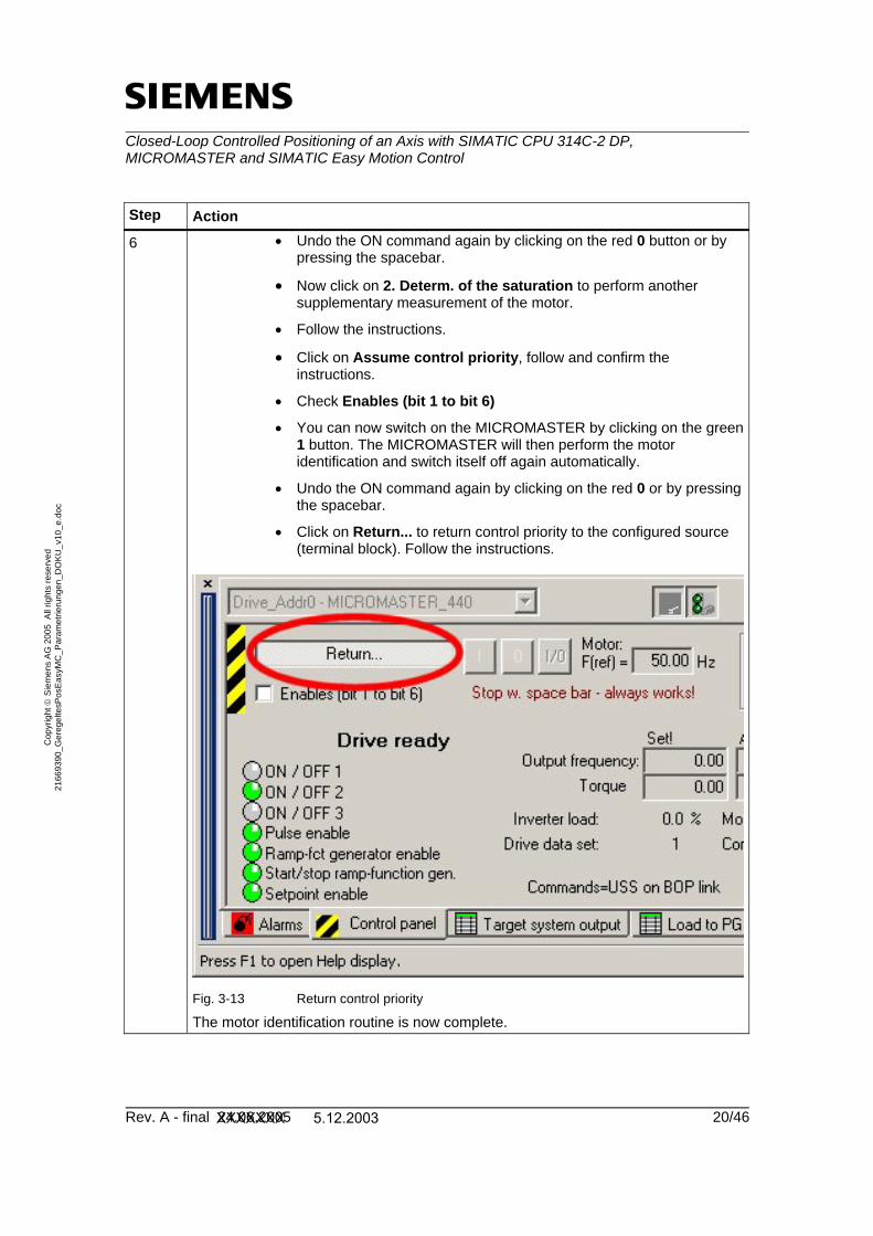
6 • Undo the ON command again by clicking on the red 0 button or by pressing the spacebar.
• Now click on 2. Determ. of the saturation to perform another supplementary measurement of the motor.
• Follow the instructions.
• Click on Assume control priority, follow and confirm the instructions.
• Check Enables (bit 1 to bit 6)
• You can now switch on the MICROMASTER by clicking on the green 1 button. The MICROMASTER will then perform the motor identification and switch itself off again automatically.
• Undo the ON command again by clicking on the red 0 or by pressing the spacebar.
• Click on Return... to return control priority to the configured source (terminal block). Follow the instructions.
Fig. 3-13 Return control priority
The motor identification routine is now complete.
XXXXXXX 5.12.2003

Closed-Loop Controlled Positioning of an Axis with SIMATIC CPU 314C-2 DP, MICROMASTER and SIMATIC Easy Motion Control
Rev. A - final 24.06.2005 21/46
Cop
yrig
ht ©
Sie
men
s A
G 2
005
All
right
s re
serv
ed
2166
9390
_Ger
egel
tesP
osE
asyM
C_P
aram
etrie
rung
en_D
OK
U_v
10_e
.doc
3.6 Check the Encoder Connection
Danger The motor is switched on and starts turning below. Safety devices, such as limit switches, are not active yet because the drive is operated solely by means of closed-loop speed control. Make sure that no injuries or damage occur as a result.
Note The drive is normally set up to rotate clockwise with a positive setpoint. The direction of rotation is defined looking from the load machine towards the motor shaft.
Fig. 3-14 Motor rotating clockwise
Table 3-5 Check the encoder connection
Step Action
1 Double click on Terminals/bus in the tree diagram and select the Digital outputs page in the right pane.
2 Parameterize digital output 3 to r52 Bit.12 (Motor holding brake active).
Fig. 3-15 Parameterize digital output 3
XXXXXXX 5.12.2003

Closed-Loop Controlled Positioning of an Axis with SIMATIC CPU 314C-2 DP, MICROMASTER and SIMATIC Easy Motion Control
Rev. A - final 24.06.2005 22/46
Cop
yrig
ht ©
Sie
men
s A
G 2
005
All
right
s re
serv
ed
2166
9390
_Ger
egel
tesP
osE
asyM
C_P
aram
etrie
rung
en_D
OK
U_v
10_e
.doc
Step Action
3 Double click on Extended and Shutdown functions in the tree diagram. Scroll down and enable the motor holding brake.
Fig. 3-16 Enable the MHB
When selecting the Opening delay time, allow for the fact that the motor is magnetized and for the load to be held when the brake is open. When selecting the Closing delay time, allow for the fact that the brake is closed and for the load to be held when the motor is switched off. When selecting the minimum frequency, make sure that the load can be held securely. If you have a pulsed resistor connected, enable the dynamic deceleration by entering a 5% duty cycle (1).
4 Activate the Expert list (see step 2 in Table 3-4 Parameterize the Motor Data)
5 Set parameter 1300[0] to V/f with linear charac. (0) in the expert list. This causes the drive to move without encoder return, which means that if the encoder is incorrectly wired, this will not cause the drive to overspeed.
6 Scroll down until you can see r61 (rotor speed). 7 Retrieve control priority again and assign the enable bits 1 to 6.
XXXXXXX 5.12.2003

Closed-Loop Controlled Positioning of an Axis with SIMATIC CPU 314C-2 DP, MICROMASTER and SIMATIC Easy Motion Control
Rev. A - final 24.06.2005 23/46
Cop
yrig
ht ©
Sie
men
s A
G 2
005
All
right
s re
serv
ed
2166
9390
_Ger
egel
tesP
osE
asyM
C_P
aram
etrie
rung
en_D
OK
U_v
10_e
.doc
Step Action
8 Set the setpoint standardization to 50 Hz. Slide the elevator bar to approx. 10%, which means that approx. 5Hz is sent as the setpoint.
Fig. 3-17 Setpoint 9 Switch the drive on (green 1). 10 The drive now rotates at a frequency of approx. 5 Hz or at approx.
135 rpm. Check the display for parameter r61. This has to be positive and should fluctuate at a value between 4 and 5 Hz. If so, slowly raise the setpoint by sliding the elevator bar up to 50 Hz. Parameter r61 must always show a little less than the setpoint. This is due to the slip in the asynchronous motor. If parameter r61 is not working properly, follow the troubleshooting instructions in the next step. If parameter r61 is working properly, switch off again (red 0) and continue with Table 3-6 Optimize the speed controller.
XXXXXXX 5.12.2003

Closed-Loop Controlled Positioning of an Axis with SIMATIC CPU 314C-2 DP, MICROMASTER and SIMATIC Easy Motion Control
Rev. A - final 24.06.2005 24/46
Cop
yrig
ht ©
Sie
men
s A
G 2
005
All
right
s re
serv
ed
2166
9390
_Ger
egel
tesP
osE
asyM
C_P
aram
etrie
rung
en_D
OK
U_v
10_e
.doc
Step Action
11 Instructions on troubleshooting: If the value is negative and lies between 4 and 5 Hz, switch the motor off again and select one of the following measures:
• Switch two motor phases (Warning! 230 V, wait for the inverter to discharge!)
• Switch tracks A and B in the encoder (as well as AN and BN, if they are used)
• Switch parameter P 1820[0].
If the value fluctuates sharply, this probably indicates that some pulses are not being detected. Check the encoder wiring. Use the A and B LEDs in the encoder evaluation in the MICROMASTER for control purposes. (See section 5 of the MICROMASTER, Encoder Module, Operating Instructions) The A and B LEDs must exhibit the following sequence of lights when the drive is turned slowly by hand.
• both off
• only LED 1 on
• both on
• only LED 2 on
• both off (cycle starts again)
Depending on the direction in which the drive turns, track A = LED 1 and track B = LED 2 or vice versa.
11 (contd.) If the value of r61 fluctuates around a value other than 4 to 5 Hz, this probably indicates that you have entered an incorrect stroke number in P408[0]. Keep repeating the encoder test until the value of r61 is correct. If parameter r61 is working properly, switch off again (red 0) and continue with Table 3-6 Optimize the speed controller.
XXXXXXX 5.12.2003

Closed-Loop Controlled Positioning of an Axis with SIMATIC CPU 314C-2 DP, MICROMASTER and SIMATIC Easy Motion Control
Rev. A - final 24.06.2005 25/46
Cop
yrig
ht ©
Sie
men
s A
G 2
005
All
right
s re
serv
ed
2166
9390
_Ger
egel
tesP
osE
asyM
C_P
aram
etrie
rung
en_D
OK
U_v
10_e
.doc
3.7 Optimize the Speed Controller
Table 3-6 Optimize the speed controller
Step Action
1 In order to optimize the speed controller, the entire load should be connected to the motor. This is the only way of optimizing the speed controller correctly. The drive turns in a positive direction during optimization.
2 Set parameter 1300[0] to Vector control with sensor (21) via the expert list.
3 Double click on Extended and Speed controller in the tree diagram.
4 Click on the Start optimization button and follow the instructions. 5 If necessary, assign the enable bits 1 to 6 again and switch the
drive on. 6 Following optimization, the drive switches off automatically. Remove
enable bits 1 to 6 and return the control priority.
XXXXXXX 5.12.2003

Closed-Loop Controlled Positioning of an Axis with SIMATIC CPU 314C-2 DP, MICROMASTER and SIMATIC Easy Motion Control
Rev. A - final 24.06.2005 26/46
Cop
yrig
ht ©
Sie
men
s A
G 2
005
All
right
s re
serv
ed
2166
9390
_Ger
egel
tesP
osE
asyM
C_P
aram
etrie
rung
en_D
OK
U_v
10_e
.doc
3.8 Close the Parameterization
Table 3-7 Close the parameterization
Step Action
1 The MICROMASTER 440 has a VDC controller which influences the output frequency, depending on the level of the intermediate circuit voltage, in order to prevent it cutting off due to a malfunction. However, as this can have a bearing on positioning, it should be switched off for positioning tasks. For this purpose, set P1240[0] to Vdc controller disabled (0) in the expert list.
Fig. 3-18 Disable Vdc controller
XXXXXXX 5.12.2003

Closed-Loop Controlled Positioning of an Axis with SIMATIC CPU 314C-2 DP, MICROMASTER and SIMATIC Easy Motion Control
Rev. A - final 24.06.2005 27/46
Cop
yrig
ht ©
Sie
men
s A
G 2
005
All
right
s re
serv
ed
2166
9390
_Ger
egel
tesP
osE
asyM
C_P
aram
etrie
rung
en_D
OK
U_v
10_e
.doc
Step Action
2 In order to input the setpoint via the analog input, parameters must be assigned to it. To do this, select Terminals/bus in the project navigator and then the Analog Inputs tab. Set Bipolar voltage input ( -10V to +10V) (4). Ensure that –10V –100% and +10V +100% are assigned.
Fig. 3-19 Parameterize analog input 1
3 As the default source of the switch-on command is digital input 1, this may not be changed.
XXXXXXX 5.12.2003

Closed-Loop Controlled Positioning of an Axis with SIMATIC CPU 314C-2 DP, MICROMASTER and SIMATIC Easy Motion Control
Rev. A - final 24.06.2005 28/46
Cop
yrig
ht ©
Sie
men
s A
G 2
005
All
right
s re
serv
ed
2166
9390
_Ger
egel
tesP
osE
asyM
C_P
aram
etrie
rung
en_D
OK
U_v
10_e
.doc
4 Ensure that the AIN1 switch on the MICROMASTER is set to OFF to enable it to work as a voltage input.
Fig. 6-4 Selection function, analog input
Note If the ON command and the setpoint are transmitted via the PROFIBUS, CB on COM link (6) must be specified when entering the drive configuration:
Fig. 3-20 Selection of the PROFIBUS in the drive configuration
XXXXXXX 5.12.2003

Closed-Loop Controlled Positioning of an Axis with SIMATIC CPU 314C-2 DP, MICROMASTER and SIMATIC Easy Motion Control
Rev. A - final 24.06.2005 29/46
Cop
yrig
ht ©
Sie
men
s A
G 2
005
All
right
s re
serv
ed
2166
9390
_Ger
egel
tesP
osE
asyM
C_P
aram
etrie
rung
en_D
OK
U_v
10_e
.doc
3.9 Save the Parameterization
Step Action
1 Now disconnect from the target system by clicking on the Disconnect button.
Fig. 3-21 Disconnect from target system
Check Save changes and Copy RAM to ROM in the window below to enable the data/parameters to be saved in the MICROMASTER and in the PC/PG. This may take a few minutes.
Fig. 3-22 Save data
2 The commissioning of the MICROMASTER has now been concluded.
Note If you have completed the commissioning of the MICROMASTER via the serial interface and USS and now wish to configure the S7, you need to switch the PC/PG interface back to MPI or PROFIBUS.
XXXXXXX 5.12.2003

Closed-Loop Controlled Positioning of an Axis with SIMATIC CPU 314C-2 DP, MICROMASTER and SIMATIC Easy Motion Control
Rev. A - final 24.06.2005 30/46
Cop
yrig
ht ©
Sie
men
s A
G 2
005
All
right
s re
serv
ed
2166
9390
_Ger
egel
tesP
osE
asyM
C_P
aram
etrie
rung
en_D
OK
U_v
10_e
.doc
4 Parameterization of the CPU 314C-2 DP
4.1 Parameterization of the Internal Counter
The following properties should be set in the HW Config for the CPU314C in the Count submodule:
Fig. 4-1 Parameterization of the counter
Note If rotary encoder quadruple is activated in the HW Config, enter the quadruple pulse count in the axis DBs for Easy Motion Control!
XXXXXXX 5.12.2003

Closed-Loop Controlled Positioning of an Axis with SIMATIC CPU 314C-2 DP, MICROMASTER and SIMATIC Easy Motion Control
Rev. A - final 24.06.2005 31/46
Cop
yrig
ht ©
Sie
men
s A
G 2
005
All
right
s re
serv
ed
2166
9390
_Ger
egel
tesP
osE
asyM
C_P
aram
etrie
rung
en_D
OK
U_v
10_e
.doc
4.2 Parameterization of the Analog Interface
Set the analog output to ± 10V in the properties for the CPU, submodule AI5/AO2 in the HW Config:
Fig. 4-2 Parameterization of the analog output
XXXXXXX 5.12.2003

Closed-Loop Controlled Positioning of an Axis with SIMATIC CPU 314C-2 DP, MICROMASTER and SIMATIC Easy Motion Control
Rev. A - final 24.06.2005 32/46
Cop
yrig
ht ©
Sie
men
s A
G 2
005
All
right
s re
serv
ed
2166
9390
_Ger
egel
tesP
osE
asyM
C_P
aram
etrie
rung
en_D
OK
U_v
10_e
.doc
5 Parameterization of the Motion Axis in Easy Motion Control
5.1 Defining the Operating Parameters
The following criteria apply in the storage lift application:
Table 5-1 Technical data for the high-bay store
Components Dimensions
Cable winch incl. motor: Diameter: 15 cm Inertia torque: 0.0076 kgm2
(relative to the motor spindle)
Max. acceleration: 0.45 m/s2
Transmission ratio: 1:10
Encoder: The sample application involves using gears, which are simulated via settings in Easy Motion Control. As the encoder sits on the motor axis, the correct encoder data is entered in the MICROMASTER, enabling it to activate the motor correctly. In the case of Easy Motion Control however, the transmission ratio is factored in, making it appear to Easy Motion Control as though the encoder is sitting on the load side. MICROMASTER: 1000 pulses per revolution Easy Motion Control: 10000 pulses per revolution
Distance per revolution: As the maximum counting frequency of the CPU314C is 60 kHz, this yields a maximum encoder speed of 60 rps or 3600 rps in the case of an encoder with a frequency of 1000 pulses per revolution. The maximum speed of the motor is 1500 rpm, thus representing the maximum speed of the system. This means that the maximum speed on the load side of the gearbox is 150 rpm. Based on a diameter of 15 cm, this works out at a distance of 471.21 mm per revolution.
Maximum velocity: Rotating at a maximum velocity of 1500 rpm, this yields a maximum positioning velocity of 1178.10 mm/s. The value entered in the axis DB is rounded down to 1000 mm/s.
Maximum acceleration: The maximum default acceleration is 450 mm/s².
Estimation of the maximum positioning time: Disregarding the acceleration ramps, it would take approx. 13 s to cover a distance of 125,000 mm.
XXXXXXX 5.12.2003

Closed-Loop Controlled Positioning of an Axis with SIMATIC CPU 314C-2 DP, MICROMASTER and SIMATIC Easy Motion Control
Rev. A - final 24.06.2005 33/46
Cop
yrig
ht ©
Sie
men
s A
G 2
005
All
right
s re
serv
ed
2166
9390
_Ger
egel
tesP
osE
asyM
C_P
aram
etrie
rung
en_D
OK
U_v
10_e
.doc
5.2 Parameterization of the Axis Parameters
Table 5-2 Parameterization of the axis parameters
Step Action
1 Create an axis DB with the aid of the Easy Motion Control parameterization user interface:
• Start Easy Motion Control.
• Open the project in which the axis is to be used.
• Enter the name of the database that you wish to use or create, e.g. DB100, and click on OK to confirm.
Fig. 5-1 Create a new axis DB
XXXXXXX 5.12.2003

Closed-Loop Controlled Positioning of an Axis with SIMATIC CPU 314C-2 DP, MICROMASTER and SIMATIC Easy Motion Control
Rev. A - final 24.06.2005 34/46
Cop
yrig
ht ©
Sie
men
s A
G 2
005
All
right
s re
serv
ed
2166
9390
_Ger
egel
tesP
osE
asyM
C_P
aram
etrie
rung
en_D
OK
U_v
10_e
.doc
Step Action
2 Enter the configuration: • Select the entry CPU314C as the input driver.
The module address for inputs and outputs is the address assigned to the CPU314C's counting module in the HW Config. The channel number is the number of the channel being used.
• Select the entry CPU314C as the input driver. The module address for inputs and outputs is the address assigned to the CPU314C's analog output module in the HW Config. The channel number is the number of the channel being used.
Fig. 5-2 Easy Motion Control: Configuration
XXXXXXX 5.12.2003

Closed-Loop Controlled Positioning of an Axis with SIMATIC CPU 314C-2 DP, MICROMASTER and SIMATIC Easy Motion Control
Rev. A - final 24.06.2005 35/46
Cop
yrig
ht ©
Sie
men
s A
G 2
005
All
right
s re
serv
ed
2166
9390
_Ger
egel
tesP
osE
asyM
C_P
aram
etrie
rung
en_D
OK
U_v
10_e
.doc
Step Action
3 Specify the axis parameters on the next tab: • Check Linear axis.
• Enter –500 and13000 mm for the 'SW limit switch'.
• The 'scan time' is 0.25 s, although this is also entered in the first pass of the OB35.
• The 'maximum axis velocity' is 1000 mm/s.
• The 'velocity override' remains at 100%.
• The 'axis accelerations' are to be configured at 450 mm/s2.
Fig. 5-3 Easy Motion Control: Axis parameters
XXXXXXX 5.12.2003

Closed-Loop Controlled Positioning of an Axis with SIMATIC CPU 314C-2 DP, MICROMASTER and SIMATIC Easy Motion Control
Rev. A - final 24.06.2005 36/46
Cop
yrig
ht ©
Sie
men
s A
G 2
005
All
right
s re
serv
ed
2166
9390
_Ger
egel
tesP
osE
asyM
C_P
aram
etrie
rung
en_D
OK
U_v
10_e
.doc
Step Action
4 Specify the parameters for the encoders, controller and motor on the next tab:
• The 'steps per encoder revolution' is 40000. This allows for the rotary encoder quadruple enabled in the HW Config, and the quadruple pulse count has been used. The factor of 10 is also added through the gear simulation.
• The 'axis distance per encoder revolution' is 471.21 mm.
• The 'set encoder polarity' is defined later on during commissioning.
• The 'controller gain' is defined later on during commissioning.
• The 'manual setpoint velocity' remains at 10 mm/s.
• The 'reference value for maximum axis velocity' is 10V.
• The 'offset compensation' is 0.
• The 'set drive polarity' is defined later on during commissioning.
Fig. 5-4 Easy Motion Control: Encoder and Controller XXXXXXX 5.12.2003

Closed-Loop Controlled Positioning of an Axis with SIMATIC CPU 314C-2 DP, MICROMASTER and SIMATIC Easy Motion Control
Rev. A - final 24.06.2005 37/46
Cop
yrig
ht ©
Sie
men
s A
G 2
005
All
right
s re
serv
ed
2166
9390
_Ger
egel
tesP
osE
asyM
C_P
aram
etrie
rung
en_D
OK
U_v
10_e
.doc
Step Action
5 Specify the parameters for the monitors on the next tab: • The 'target range' is 100 mm.
• The 'standstill range' is 200 mm.
• The 'monitoring time for target approach' remains at 1 s.
• The 'deceleration for hard stop' remains at 1000 mm/s².
• The 'max. allowed following distance' is 250 mm.
Fig. 5-5 Easy Motion Control: Monitors
XXXXXXX 5.12.2003

Closed-Loop Controlled Positioning of an Axis with SIMATIC CPU 314C-2 DP, MICROMASTER and SIMATIC Easy Motion Control
Rev. A - final 24.06.2005 38/46
Cop
yrig
ht ©
Sie
men
s A
G 2
005
All
right
s re
serv
ed
2166
9390
_Ger
egel
tesP
osE
asyM
C_P
aram
etrie
rung
en_D
OK
U_v
10_e
.doc
5.3 Move the Axis during Commissioning
Once the axis data has been entered and the controller has been loaded, EMC commissioning tools may be used. The motor and encoder polarity are checked, and appropriate switches are made or parameters set in the axis DB.
The configured axis DB must be available in the controller. The input driver must be factored in the CPU, but not the output driver, however.
The MICROMASTER has to be configured and connected to the 230V network. The wiring must be implemented between the controller, the MICROMASTER and the encoder.
5.3.1 Wiring Test
In the wiring test, the motor and encoder polarity are checked, and appropriate switches are made in the axis DB.
Note The drive is normally set up to rotate clockwise with a positive setpoint. The direction of rotation is defined looking from the load machine.
Fig. 5-6 Motor rotating clockwise
• Retrieve the application from the SIMATIC Manager and load it into the controller.
• Open the OB35 in the LAD/FBD/STL editor.
• Enable the SPA END jump command in the 2nd line of network 3 by deleting the comment characters (//). Load the changed OB35 into the controller.
• Call up the DB100 axis DB with the Easy Motion Control software by double-clicking on the DB100 in the SIMATIC Manager.
• Select Commissioning and the Wiring test.
• Start the drive with the aid of the signal_check variable block by setting "idb_io".Drive_enabled to 1 or true.
Note The motor may start to turn slowly on account of the analog setpoint transmission!
XXXXXXX 5.12.2003

Closed-Loop Controlled Positioning of an Axis with SIMATIC CPU 314C-2 DP, MICROMASTER and SIMATIC Easy Motion Control
Rev. A - final 24.06.2005 39/46
Cop
yrig
ht ©
Sie
men
s A
G 2
005
All
right
s re
serv
ed
2166
9390
_Ger
egel
tesP
osE
asyM
C_P
aram
etrie
rung
en_D
OK
U_v
10_e
.doc
• Follow the wizard's instructions.
Fig. 5-7 Wiring test
• Stop the drive with the aid of the signal_check variable block by setting "idb_io".Drive_enabled to 0 or false.
• Save the axis DB and load it into the controller.
Note If the drive starts turning slowly after being released, define the offset compensation, see section 0 5.3.2 Offset Compensation.
• Disable the SPA END jump command in the 2nd line of network 3 by inserting the comment characters (//) at the start of the line. Save the changed OB35 und and load it into the controller.
XXXXXXX 5.12.2003

Closed-Loop Controlled Positioning of an Axis with SIMATIC CPU 314C-2 DP, MICROMASTER and SIMATIC Easy Motion Control
Rev. A - final 24.06.2005 40/46
Cop
yrig
ht ©
Sie
men
s A
G 2
005
All
right
s re
serv
ed
2166
9390
_Ger
egel
tesP
osE
asyM
C_P
aram
etrie
rung
en_D
OK
U_v
10_e
.doc
5.3.2 Offset Compensation
If the drive starts turning slowly after being released, define the offset compensation:
• In order to do this, start the drive once again via the variable table and call up the wiring test, as described in section 0 5.3.1 Wiring Test (disable the command in OB35, etc.)
• Now, slide the elevator bar to select the setpoint until the drive comes to a stop with the move button pressed.
• Take a note this value and stop the wiring test.
• Enter this value into the offset compensation field on the Encoders/Controller/Motor tab of the Easy Motion Control parameterization software.
• Disable the SPA END jump command in the 2nd line of network 3 by inserting the comment characters (//) at the start of the line. Save the changed OB35 und and load it into the controller.
Note The offset compensation does not take effect while the output driver is not active, e.g. in the wiring test; consequently, it cannot be checked. If the output driver is factored in, the closed-loop position control is also activated; it automatically also compensates for an offset, which also means that the offset compensation cannot be checked. However, if an offset has already been compensated for via the offset compensation, this does not have to be done by the closed-loop position controller, improving the control performance.
XXXXXXX 5.12.2003

Closed-Loop Controlled Positioning of an Axis with SIMATIC CPU 314C-2 DP, MICROMASTER and SIMATIC Easy Motion Control
Rev. A - final 24.06.2005 41/46
Cop
yrig
ht ©
Sie
men
s A
G 2
005
All
right
s re
serv
ed
2166
9390
_Ger
egel
tesP
osE
asyM
C_P
aram
etrie
rung
en_D
OK
U_v
10_e
.doc
5.3.3 Closed-Loop Position Control Optimization
The optimum controller gain can be determined experimentally at the axis.
• Call up the DB100 axis DB with the Easy Motion Control software by double-clicking on the DB100 in the SIMATIC Manager.
• Select the Encoders/Controller/Motor tab.
• Move the axis with the aid of the HMI, e.g. by jogging.
• Raise the controller gain in increments of 1.0 until the axis starts to fluctuate in motion or at a standstill.
• If this happens, reduce the controller gain until there is no further tendency to fluctuate visible.
• Save the axis DB and load it into the controller.
XXXXXXX 5.12.2003

Closed-Loop Controlled Positioning of an Axis with SIMATIC CPU 314C-2 DP, MICROMASTER and SIMATIC Easy Motion Control
Rev. A - final 24.06.2005 42/46
Cop
yrig
ht ©
Sie
men
s A
G 2
005
All
right
s re
serv
ed
2166
9390
_Ger
egel
tesP
osE
asyM
C_P
aram
etrie
rung
en_D
OK
U_v
10_e
.doc
6 Parameterization of the SIMATIC NET OPC Server
Requirements
Install SIMATIC NET with the aid of the installation program on the SIMATIC NET CD.
When you select the CD, bear in mind that the version being used is operating system-dependent:
Table 6-1 SIMATIC NET versions
Operating system SIMATIC NET version
Windows 9x, NT, 2000 6.0 Windows XP 6.1
6.1 Test the OPC Configuration with OPC Scout
Table 6-2 Test OP configuration
Step Action
1 The precondition for the test is that the S7 program is factored into CPU computations, and that the CPU is connected to the PC/PG via MPI.
2 Open the OPC Scout via the Start menu (e.g. Start, SIMATIC, SIMATIC NET, PROFIBUS, SOFTNET PROFIBUS, OPC Scout)
3 Double click on OPC SimaticNET and create a new group, e.g. Test:
Fig. 6-1 OPC Scout: Create a new group
XXXXXXX 5.12.2003

Closed-Loop Controlled Positioning of an Axis with SIMATIC CPU 314C-2 DP, MICROMASTER and SIMATIC Easy Motion Control
Rev. A - final 24.06.2005 43/46
Cop
yrig
ht ©
Sie
men
s A
G 2
005
All
right
s re
serv
ed
2166
9390
_Ger
egel
tesP
osE
asyM
C_P
aram
etrie
rung
en_D
OK
U_v
10_e
.doc
Step Action
4 • Open the Test group by double clicking on it.
• Expand the S7 area:
• Add a new variable by right-clicking in the pane on the extreme right: enter the following: S7:[S7 connection_1]DB202,INT0,3 This means that three integer values are read from DB202.
• Click on Add Item and OK to confirm.
Fig. 6-2 OPC Scout: Insert connection
XXXXXXX 5.12.2003

Closed-Loop Controlled Positioning of an Axis with SIMATIC CPU 314C-2 DP, MICROMASTER and SIMATIC Easy Motion Control
Rev. A - final 24.06.2005 44/46
Cop
yrig
ht ©
Sie
men
s A
G 2
005
All
right
s re
serv
ed
2166
9390
_Ger
egel
tesP
osE
asyM
C_P
aram
etrie
rung
en_D
OK
U_v
10_e
.doc
Step Action
5 Once the connection has been established, the current values from DB202 are displayed under Value (i.e. values 25, 600, 105 in the screenshot).
Fig. 6-3 OPC Scout: Value display
XXXXXXX 5.12.2003

Closed-Loop Controlled Positioning of an Axis with SIMATIC CPU 314C-2 DP, MICROMASTER and SIMATIC Easy Motion Control
Rev. A - final 24.06.2005 45/46
Cop
yrig
ht ©
Sie
men
s A
G 2
005
All
right
s re
serv
ed
2166
9390
_Ger
egel
tesP
osE
asyM
C_P
aram
etrie
rung
en_D
OK
U_v
10_e
.doc
7 Internet Links
This list is by no means complete and only reflects a selection of the suitable Internet links available.
Table 7-1 Internet links
Topic Area Link
\1\ Link to this Application http://support.automation.siemens.com/WW/view/en/21669390
\2\ Easy Motion Control Manual www.ad.siemens.de/support
Select product support Open the following directories in the tree:
• Automation technology
• SIMATIC industrial automation systems
• SIMATIC industrial software
• Software for SIMATIC S7/C7/WinAC
• Runtime software
• Easy Motion Control
Look here under Manuals / OIs \3\ MM440 Operating Manual www.ad.siemens.de/support
Select product support Open the following directories in the tree:
• Drive technology
• AC inverter
• Low-voltage inverter
• MICROMASTER 4
• MICROMASTER 440
Look here under Manuals / OIs
XXXXXXX 5.12.2003

Closed-Loop Controlled Positioning of an Axis with SIMATIC CPU 314C-2 DP, MICROMASTER and SIMATIC Easy Motion Control
Rev. A - final 24.06.2005 46/46
Cop
yrig
ht ©
Sie
men
s A
G 2
005
All
right
s re
serv
ed
2166
9390
_Ger
egel
tesP
osE
asyM
C_P
aram
etrie
rung
en_D
OK
U_v
10_e
.doc
Topic Area Link
\4\ STARTER (stand-alone) for
MICROMASTER www.ad.siemens.de/support Select product support
• Drive technology
• (Engineering) software
• Low-voltage inverter
• STARTER commissioning tool
Look here under Downloads
XXXXXXX 5.12.2003