applications see application list inside chevrolet/suzuki
TRANSCRIPT

METRA. THE WORLD’S BEST KITS.™
© COPYRIGHT 2004-2011 METRA ELECTRONICS CORPORATION
APPLICATIONS
1-800-221-0932 metraonline.com
INSTALLATION INSTRUCTIONS FOR PART 99-7951
Panel Removal Tool • Phillips Screwdriver • Small Flat Blade Screwdriver
TOOLS REQUIRED
Chevrolet/Suzuki/Pontiac multi-kit2004 - 2008
95-7951
BA
• A) Double DIN Trim Plate • B) Double DIN Brackets
KIT FEATURES
KIT COMPONENTS
• Double DIN radio provision• Stacked ISO units provision
WIRING & ANTENNA CONNECTIONS (Sold Separately) Wiring Harness: • 70-2105 GM harness 2006-up• 70-8405 GM/Suzuki/Daewoo harness 1999-upAntenna Adapter:• 40-CR10 Chryler antenna adapter 2002-up
See application list inside

95-7951
Table of Contents
Applications
KNOWLEDGE IS POWEREnhance your installation and fabrication skills by enrolling in the most recognized and respected mobile electronics school in our industry.Log onto www.installerinstitute.com or call 800-354-6782 for more information and take steps toward a better tomorrow.
Metra recommends MECP certified technicians
CautionMetra recommends disconnecting the negative battery terminal before beginning any installation. All accessories, switches, and especially air bag indicator lights must be plugged in before reconnecting the battery or cycling the ignition.
*NOTE: Refer also to the instructions included with the aftermarket radio.
ChevroletAveo 2004-2006Aveo Hatchback 2007-2008
SuzukiForenza 2004-2008Reno 2005-2008Verona 2004-2006
PontiacG3 Hatchback 2007
Dash Disassembly
– Chevrolet Aveo 2004-2006 3– Chevrolet Aveo Hatchback 2007-2008 3– Pontiac G3 Hatchback 2007 3– Suzuki Forenza 2004-2008 4-5– Suzuki Reno 2005-2008 4-5– Suzuki Verona 2004-2006 6
Kit Assembly
– Double DIN radio provision 7-8– Stacked ISO mount units provision 9-10

1. Unclip and remove the trim panels from both sides of radio/climate controls. (Figure A)
2. Remove (4) Phillips screws securing the radio. Unplug and remove radio. (Figure B)
Continue to kit assembly
3
Chevrolet Aveo 2004-2006 Chevrolet Aveo Hatchback 2007-2008
Pontiac G3 Hatchback 2007
Dash Disassembly 95-7951
(Figure A)
(Figure B)

4
Dash Disassembly 95-7951
Suzuki Forenza 2004-2008 Suzuki Reno 2005-2008
1. Disconnect air selector cable on driver’s side of center console behind dash above accelerator pedal. (Figure A & B)
2. Open glove box and remove (5) Phillips screws ((3) on top and (2) on bottom) then remove entire glove box.
3. Disconnect temperature selector cable on passenger side of center console behind glove box. (Figure C)
Continued on next page
Inside of Glove Box
(Figure A)
(Figure B)
(Figure C)

5
Dash Disassembly 95-7951
Suzuki Forenza 2004-2008 Suzuki Reno 2005-2008
4. Unsnap and remove entire panel surrounding radio. NOTE: The clips holding radio panel to dash are very strong. (Figure D)
5. Remove (4) 10 mm bolts securing radio. Unplug and remove radio. (Figure E)
Continue to kit assemblyAM/FM
TAPE
CDTUNE
1 2 3
4 5 6
BASS
MUTE
EQ
AST
SCAN
(Figure D)
(Figure E)
6
Dash Disassembly 95-7951
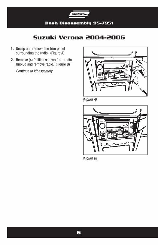
Suzuki Verona 2004-2006
1. Unclip and remove the trim panel surrounding the radio. (Figure A)
2. Remove (4) Phillips screws from radio. Unplug and remove radio. (Figure B)
Continue to kit assembly
(Figure A)
(Figure B)

7
Kit Assembly 95-7951
Double DIN radio provision
NOTE: For the Chevrolet Aveo 2004-06, Chevrolet Aveo Hatchback 2007-08, Pontiac G3 Hatchback 2007 and Suzuki Verona 2004-06, cut and remove front lower mounting tabs from the Double DIN trim plate (Figure A). For the Suzuki Forenza 2004-08 and the Suzuki Reno 2005-08, cut the rear lower mounting tabs (Figure B).
NOTE: The Verona 2004-2006 sub dash will need to be trimmed slightly for proper fit. Refer to illustration. (Figures C and D)
Continued on next page
CUTHEREON BOTH SIDES
(Figure C)
(Figure D)
(Figure B)
(Figure A)

8
Kit Assembly 95-7951
1. Locate the factory wiring harness in the dash. Metra recommends using the proper mating adapter from Metra or AXXESS. Re-connect the negative battery terminal and test the unit for proper operation.
2. Snap the Double DIN brackets to the outside edge of the Double DIN trim plate. (Figure E)
3. Slide the Double DIN radio into the bracket/trim plate assembly and secure the radio to the assembly using the screws supplied with the radio. (Figure F)
4. Reassemble dash in reverse order of disassembly.
Double DIN radio provision
(Figure E)
(Figure F)

9
Kit Assembly 95-7951
Stacked ISO mount units provision
NOTE: For the Chevrolet Aveo 2004-06, Chevrolet Aveo Hatchback 2007-08, Pontiac G3 Hatchback 2007 and Suzuki Verona 2004-06, cut and remove front lower mounting tabs from the Double DIN trim plate (Figure A). For the Suzuki Forenza 2004-08 and the Suzuki Reno 2005-08, cut the rear lower mounting tabs (Figure B).
NOTE: The Verona 2004-2006 sub dash will need to be trimmed slightly for proper fit. Refer to illustration. (Figures C and D)
Continued on next page
CUTHEREON BOTH SIDES
(Figure C)
(Figure D)
(Figure B)
(Figure A)

Kit Assembly 95-7951
10
Stacked ISO mount units provision
(Figure E)
(Figure F)
1. Locate the factory wiring harness in the dash. Metra recommends using the proper mating adapter from Metra or AXXESS. Re-connect the negative battery terminal and test the unit for proper operation.
2. Snap the Double DIN brackets to the outside edge of the Double DIN trim plate. (Figure E)
3. Slide the stacked ISO units into the bracket/trim plate assembly and secure the units to the assembly using the screws supplied with the units. (Figure F)
4. Reassemble dash in reverse order of disassembly.

Notes

METRA. THE WORLD’S BEST KITS.™
© COPYRIGHT 2004-2011 METRA ELECTRONICS CORPORATION 1-800-221-0932 metraonline.com
INSTALLATION INSTRUCTIONS FOR PART 99-7951
REV.
5/2
5/11