applied computational electromagnetics society journalnihad/files/pap/10_dib_aces... · applied...
TRANSCRIPT
AppliedComputationalElectromagneticsSocietyJournal
Editor-in-ChiefAtef Z. Elsherbeni
November 2007Vol. 22 No. 3ISSN 1054-4887
GENERAL PURPOSE AND SCOPE: The Applied Computational Electromagnetics Society (ACES) Journal hereinafter known as the ACES Journal is devoted to the exchange of information in computational electromagnetics, to the advancement of the state-of-the art, and the promotion of related technical activities. A primary objective of the information exchange is the elimination of the need to “re-invent the wheel” to solve a previously-solved computational problem in electrical engineering, physics, or related fields of study. The technical activities promoted by this publication include code validation, performance analysis, and input/output standardization; code or technique optimization and error minimization; innovations in solution technique or in data input/output; identification of new applications for electromagnetics modeling codes and techniques; integration of computational electromagnetics techniques with new computer architectures; and correlation of computational parameters with physical mechanisms. SUBMISSIONS: The ACES Journal welcomes original, previously unpublished papers, relating to applied computational electromagnetics. Typical papers will represent the computational electromagnetics aspects of research in electrical engineering, physics, or related disciplines. However, papers which represent research in applied computational electromagnetics itself are equally acceptable. Manuscripts are to be submitted through the upload system of ACES web site http://aces.ee.olemiss.edu See “Information for Authors” on inside of back cover and at ACES web site. For additional information contact the Editor-in-Chief:
Dr. Atef Elsherbeni Department of Electrical Engineering The University of Mississippi University, MS 386377 USA Phone: 662-915-5382 Fax: 662-915-7231 Email: [email protected] SUBSCRIPTIONS: All members of the Applied Computational Electromagnetics Society who have paid their subscription fees are entitled to receive the ACES Journal with a minimum of three issues per calendar year and are entitled to download any published journal article available at http://aces.ee.olemiss.edu. Back issues, when available, are $15 each. Subscriptions to ACES is through the web site. Orders for back issues of the ACES Journal and changes of addresses should be sent directly to ACES Executive Officer: Dr. Richard W. Adler ECE Department, Code ECAB Naval Postgraduate School 833 Dyer Road, Room 437 Monterey, CA 93943-5121 USA Fax: 831-649-0300
Email: [email protected] Allow four week’s advance notice for change of address. Claims for missing issues will not be honored because of insufficient notice or address change or loss in mail unless the Executive Officer is notified within 60 days for USA and Canadian subscribers or 90 days for subscribers in other countries, from the last day of the month of publication. For information regarding reprints of individual papers or other materials, see “Information for Authors”. LIABILITY. Neither ACES, nor the ACES Journal editors, are responsible for any consequence of misinformation or claims, express or implied, in any published material in an ACES Journal issue. This also applies to advertising, for which only camera-ready copies are accepted. Authors are responsible for information contained in their papers. If any material submitted for publication includes material which has already been published elsewhere, it is the author’s responsibility to obtain written permission to reproduce such material.
APPLIED COMPUTATIONAL ELECTROMAGNETICS SOCIETY JOURNAL Editor-in-Chief Atef Z. Elsherbeni November 2007 Vol. 22 No. 3 ISSN 1054-4887
The ACES Journal is abstracted in INSPEC, in Engineering Index, DTIC, Science Citation Index Expanded, the Research Alert, and to Current Contents/Engineering, Computing & Technology. The first, fourth, and sixth illustrations on the front cover have been obtained from the Department of Electrical Engineering at the University of Mississippi. The third and fifth illustrations on the front cover have been obtained from Lawrence Livermore National Laboratory. The second illustration on the front cover has been obtained from FLUX2D software, CEDRAT S.S. France, MAGSOFT Corporation, New York.
THE APPLIED COMPUTATIONAL ELECTROMAGNETICS SOCIETY http//:aces.ee.olemiss.edu
ACES JOURNAL EDITORS
EDITOR-IN-CHIEF/ACES/JOURNAL Atef Elsherbeni University of Mississippi, EE Dept. University, MS 38677, USA MANAGING EDITOR Richard W. Adler 833 Dyer Rd, Rm 437 EC/AB NPS, Monterey, CA 93943-5121, USA ASSOCIATE EDITOR-IN-CHIEF, EMERITUS Alexander Yakovlev University of Mississippi, EE Dept. University, MS 38677, USA EDITOR-IN-CHIEF, EMERITUS Robert M. Bevensee Box 812 Alamo, CA 94507-0516, USA
ASSOCIATE EDITOR-IN-CHIEF Erdem Topsakal Mississippi State University, EE Dept. Mississippi State, MS 39762, USA EDITORIAL ASSISTANT Mohamed Al Sharkawy University of Mississippi, EE Dept. University, MS 38677, USA EDITOR-IN-CHIEF, EMERITUS Allen Glisson University of Mississippi, EE Dept. University, MS 38677, USA EDITOR-IN-CHIEF, EMERITUS Ducan C. Baker EE Dept. U. of Pretoria 0002 Pretoria, South Africa
EDITORIAL ASSISTANT Matthew J. Inman University of Mississippi, EE Dept. University, MS 38677, USA EDITOR-IN-CHIEF, EMERITUS Ahmed Kishk University of Mississippi, EE Dept. University, MS 38677, USA EDITOR-IN-CHIEF, EMERITUS David E. Stein USAF Scientific Advisory Board Washington, DC 20330, USA
ACES JOURNAL ASSOCIATE EDITORS Giandomenico Amendola
John Beggs
John Brauer
Magda El-Shenawee
Pat Foster
Cynthia M. Furse
Christian Hafner
Michael Hamid
Andy Harrison
Chun-Wen Paul Huang
Todd H. Hubing
Nathan Ida
Yasushi Kanai
Leo C. Kempel
Andrzej Krawczyk
Stanley Kubina
Samir F. Mahmoud
Ronald Marhefka
Edmund K. Miller
Krishna Naishadham
Giuseppe Pelosi
Vicente Rodriguez
Harold A. Sabbagh
John B. Schneider
Abdel Razek Sebak
Amr M. Sharawee
Norio Takahashi
NOVEMBER 2007 REVIEWERS Fan Yang
Ercument Arvas
Mohamed Al-Sharkawy
Malcolm Bibby
William A. Davis
Mohamed H. Bakr
Fernando Las-Heras
Michiko Kuroda
Yasushi Kanai
Masoud Kahrizi
Naftali (Tuli) Herscovici
John H. Beggs
Veysel Demir
Alan Taflove
Andy Harrison
Sami Barmada
Andrew F. Peterson
Michael A. Morgan
James Rautio
Darko Kajfez
Eric Michielssen
THE APPLIED COMPUTATIONAL ELECTROMAGNETICS SOCIETY
JOURNAL
Vol. 22 No. 3 November 2007 TABLE OF CONTENTS
“Eliminating Interface Reflections in Hybrid Low-Dispersion FDTD Algorithms” M. F. Hadi and R. K. Dib……………………………………………………………………306 “Finite Difference Time Domain Method for the Analysis of Transient Grounding Resistance of Buried Thin Wires” M. Goni, E. Kaneko, and A. Ametani………………………………………………………315 “Accelerated GRECO Based on a GPU” Y. ZhenLong, J. Lin, and L. WeiQing………………………………………………………321 “An Efficient Preconditioner (LESP) for Hybrid Matrices Arising in RF MEMS Switch Analysis” Z. Wang, J. L. Volakis, K. Kurabayashi, and K. Saitou…………….………………………327 “A Parallelized Monte Carlo Algorithm for the Nonlinear Poisson-Boltzmann Equation in Two Dimensions” K. Chatterjee and J. Poggie……………………..…………………………………………...333 “Electromagnetic Scattering Computation Using a Hybrid Surface and Volume Integral Equation Formulation” C. Luo and C. Lu…………………..………………………………………………………...340 “Accurate Computational Algorithm for Calculation of Input Impedance of Antennas of Arbitrarily Shaped Conducting Surfaces” K. F. A. Hussein……………………………………………………………………………..350 “Electric and Magnetic Dual Meshes to Improve Moment Method Formulations” M. F. Cátedra, O. Gutiérrez, I. González, and F. Saez de Adana …………………………..363 “Optimum Plannar Antenna Design Based on an Integration of IE3D Commercial Code and Optimization Algorithms” H. Chou, Y. Hou, and W Liao..……………………………………………………………..373 “Analysis and Design of Quad-Band Four-Section Transmission Line Impedance Transformer” H. Jwaied, F. Muwanes, and N. Dib………………………………………………………...381
“Analysis of Dielectric Loaded Scalar Horn Radiators” B. Türetken…………………………………………………………………….…………….388 “Electromagnetic Scattering Problems Utilizing a Direct, Parallel Solver” W. R. Dearholt and S. P. Castillo……….…………………………………………………...395 “Scattering from a Semi-Elliptic Channel in a Ground Plane Loaded by a Lossy or Lossless Dielectric Elliptic Shell” A-K. Mahid……………………….…………………………………………………………414 “Investigation of Wire Grid Modeling in NEC Applied to Determine Resonant Cavity Quality Factors” F. A. Pertl, A. D. Lowery, and J E. Smith….……………………………………………….420 © 2007, The Applied Computational Electromagnetics Society
Analysis and Design of Quad-Band Four-Section Transmission Line Impedance Transformer
Hussam Jwaied, Firas Muwanes, and Nihad Dib
Electrical Eng. Dept., Jordan Univ. of Science and Technology, P. O. Box 3030, Irbid 22110, Jordan, E-mail: [email protected]
Abstract − The design of four-section transmission line matching transformer, operating at four arbitrary frequencies, is presented. Standard transmission line theory is used to obtain a closed form expression that is solved using particle swarm optimization technique to find the required transformer parameters (lengths, and characteristic impedances). Different examples are presented which validate the design approach. To further validate the analysis and design approach, a microstrip line four-section quad-band transmission line transformer is designed, analyzed, fabricated and measured.
I. INTRODUCTION With the advent of multi-band operation in wireless
communication systems, it becomes essential to have matching transformers that operate at several frequencies. Recently, several papers have been published in which different techniques were proposed to design dual-frequency matching transformers [1-4]. In [1], a λ/4 -shorted stub was added to a conventional single-shunt-stub matching network that enabled impedance matching at two separate frequencies simultaneously. In [2], a novel dual-band two-section transmission line transformer (TLT) was proposed and simple design equations for the impedances and lengths of the two sections were derived in [3]. In [4], an extension of this dual-band TLT to match complex impedances was presented and applied to wideband high-frequency amplifiers. Very recently, a triple-band three-section TLT, extended from the two-section TLT concept, was designed and analyzed in [5]. Using simple transmission line theory, design expressions for the three-section TLT for three arbitrary operating frequencies were derived. Two non-linear equations were solved simultaneously via an optimization process to obtain the parameters of the transformer. As an application of these TLTs, dual-band two-section TLT and triple-band three-section TLT have been successfully used to design dual-band and triple-band Wilkinson power dividers, respectively, [6-8].
In this paper, the quad-band four-section TLT, which is matched at four arbitrary frequencies (f1, f2, f3 and f4) for any transforming ratio (ZL/Z0) is designed and analyzed. Four non-linear equations are derived using standard transmission line theory, which are then solved simultaneously using the particle swarm optimization
(PSO) technique. The PSO technique is used to find the characteristic impedances and lengths of the first two sections, from which the impedances and lengths of the other sections are obtained using the antimetry conditions [9]. The PSO algorithm is a multiple-agents optimization algorithm that was introduced by Kennedy and Eberhart [10] in 1995 while studying the social behavior of groups of animals and insects such as flocks of birds, schools of fish, and swarms of bees. Recently, this technique found many successful applications in Electromagnetics [11-13]. PSO is similar in some ways to genetic algorithms, but requires less computational bookkeeping and generally fewer lines of code, including the fact that the basic algorithm is very easy to understand and implement. It should be mentioned that other optimization techniques could be used too, but recently, we have been interested in the application of PSO method in the design of different microwave passive elements [14, 15], and antennas [16]. The interested reader can refer to [10-16], and the references therein, for details of the PSO algorithm.
II. ANALYSIS AND DESIGN
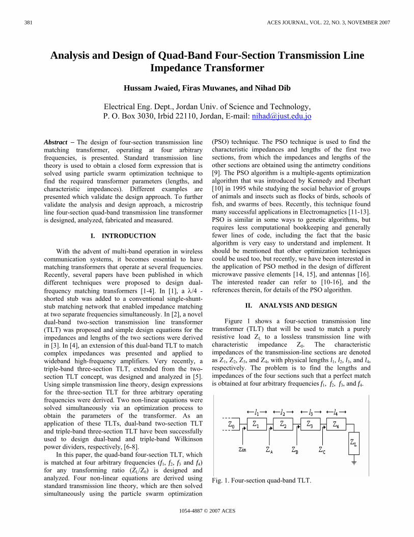
Figure 1 shows a four-section transmission line transformer (TLT) that will be used to match a purely resistive load ZL to a lossless transmission line with characteristic impedance Z0. The characteristic impedances of the transmission-line sections are denoted as Z1, Z2, Z3, and Z4, with physical lengths l1, l2, l3, and l4, respectively. The problem is to find the lengths and impedances of the four sections such that a perfect match is obtained at four arbitrary frequencies f1, f2, f3, and f4.
Fig. 1. Four-section quad-band TLT.
381
1054-4887 © 2007 ACES
ACES JOURNAL, VOL. 22, NO. 3, NOVEMBER 2007
Using standard transmission line theory, the input impedance of the four-section TLT is given by,
1 11
1 1
tan( )tan( )
Ain
A
Z jZZ ZZ jZ
ββ
+=
+ (1)
where 2 2
22 2
tan( )tan( )
BA
B
Z jZZ ZZ jZ
ββ
+=
+, (2)
3 33
3 3
tan( )tan( )
CB
C
Z jZZ Z
Z jZββ
+=
+, (3)
4 44
4 4
tan( )tan( )
LC
L
Z jZZ ZZ jZ
ββ
+=
+. (4)
For perfect matching at specific frequencies, the lengths and impedances should be chosen such that Zin = Z0 at those frequencies. Imposing this condition on equation (1) and solving for ZA gives,
0 1 11
1 0 1
tan( )tan( )A
Z jZZ Z
Z jZββ
−=
−. (5)
Solving equation (2) for ZB gives,
2 22
2 2
tan( )tan( )
AB
A
Z jZZ ZZ jZ
ββ
−=
−. (6)
Substituting equation (5) in equation (6), gives,
0 1 11 2 2
1 0 12
0 1 12 1 2
1 0 1
tan( ) tan( )tan( )
tan( ) tan( )tan( )
B
Z jZZ jZZ jZ
Z Z Z jZZ jZZ jZ
β ββ
β ββ
−−
−=
−−
−
. (7)
Another equation for ZB can be obtained by substituting equation (4) in equation (3), which gives,
4 44 3 3
4 43
4 43 4 3
4 4
tan( ) tan( )tan( )
tan( ) tan( )tan( )
L
LB
L
L
Z jZZ jZZ jZZ Z Z jZZ jZ
Z jZ
β ββ
β ββ
++
+=
++
+
. (8)
Equating the complex equations (7) and (8), we get the following two expressions,
2 11 2
1 2
3 11 3
1 3
4 11 4
1 4
3 22 3
2 3
4 22 4
2 4
343 4
3 4
1
tan( ) tan( )
tan( ) tan( )
tan( ) tan( )
tan( ) tan( )
tan( ) tan( )
tan( ) tan( )
Z Z kZ Z
Z Z kZ Z
Z Z kZ Z
Z Z kZ Z
Z Z kZ Z
ZZ kZ Z
Z
β β
β β
β β
β β
β β
β β
⎛ ⎞−⎜ ⎟
⎝ ⎠⎛ ⎞
+ −⎜ ⎟⎝ ⎠⎛ ⎞
+ −⎜ ⎟⎝ ⎠⎛ ⎞
+ −⎜ ⎟⎝ ⎠⎛ ⎞
+ −⎜ ⎟⎝ ⎠⎛ ⎞
+ −⎜ ⎟⎝ ⎠
+ 1 23 2 4
3 42 4 1 3
tan( ) tan( )(1 ),
tan( ) tan( )Z Z Zk k
Z Z Z Zβ ββ β
⎛ ⎞ ⎧ ⎫− × = −⎨ ⎬⎜ ⎟ ×⎩ ⎭⎝ ⎠
(9)
1 21 2
1 0 2 0
3 43 4
3 0 4 0
1 3 21 2 3
0 2 1 3
1 4 21 2 4
0 2 1 4
1 4
0 3
tan( ) tan( )
tan( ) tan( )
tan( ) tan( )tan( )
tan( ) tan( )tan( )
L L
L L
L
L
Z Z Z ZZ Z Z Z
ZZ Z ZZ Z Z Z
Z Z Z ZZ Z Z Z
Z Z Z ZZ Z Z Z
Z ZZ Z
β β
β β
β β β
β β β
⎛ ⎞ ⎛ ⎞− + −⎜ ⎟ ⎜ ⎟
⎝ ⎠ ⎝ ⎠⎛ ⎞ ⎛ ⎞
+ − + −⎜ ⎟ ⎜ ⎟⎝ ⎠ ⎝ ⎠⎛ ⎞
+ −⎜ ⎟⎝ ⎠⎛ ⎞
+ −⎜ ⎟⎝ ⎠
+ − 31 3 4
1 4
32 41 2 3
0 3 2 4
tan( )tan( )tan( )
tan( )tan( )tan( ) 0
L
L
Z ZZ Z
Z ZZ ZZ Z Z Z
β β β
β β β
⎛ ⎞⎜ ⎟⎝ ⎠⎛ ⎞
+ − =⎜ ⎟⎝ ⎠
(10)
where k is the impedance transforming ratio (or the normalized load impedance) defined as k=ZL/Z0.
For a compact size, the characteristics impedances must be monotonically increasing or monotonically decreasing, i.e., they should satisfy one of the following conditions [5],
For k<1: ZL < Z4 < Z3 < Z2 < Z1 < Z0 For k>1: Z0 < Z1 < Z2 < Z3 < Z4 < ZL
Moreover, since an optimized transformer, in the sense of achieving global minima of the reflection coefficient at the design frequencies, is being designed, it should satisfy the antimetry conditions given as, [9],
382JWAIED, MUWANES, DIB: ANALYSIS AND DESIGN OF QUAD-BASED FOUR-SECTION TL IMPEDANCE TRANSFORMER
l1 = l4 and l2 = l3 , (11a)
Z1Z4 = Z2Z3 = Z0ZL. (11b)
It is worth mentioning that the dual-band TLT [3] and the tri-band TLT [5] were found to satisfy these conditions too. Enforcing the above antimetry conditions on the left side of equation (10) gives a zero; that is equation (10) is satisfied if the lengths and the impedances satisfy the antimetry conditions. This validates, to some extent, that indeed the antimetry conditions have to be satisfied. On the other hand, enforcing the antimetry conditions in equation (9), and after some simplification, the following expression is obtained,
1 2
2 1
1 21 2
tan( ) tan( )2tan( ) tan( )
( 1)tan( ) tan( ) 0tan( ) tan( )
a b c
kd
β ββ β
β ββ β
+ +
−+ + =
(12)
where
⎟⎟⎠
⎞⎜⎜⎝
⎛−+⎟⎟
⎠
⎞⎜⎜⎝
⎛−= 21
212
1
1
2 zzzzkk
zz
zz
a , (13a)
212
1
zzkb −= , (13b)
222
2
zzkc −= , (13c)
21
22
22
21
zzk
zzd −= . (13d)
In equation (13), normalized impedances are used where z1=Z1/Z0, and z2=Z2/Z0. It is clear that there are four unknowns in equation (12); namely: z1, z2, l1, and l2. Now, equation (12) should be satisfied at the four design frequencies f1, f2, f3, and f4 which can be written as follows: f2=u1 f1, f3=u2 f1, and f4=u3 f1, where u1, u2, and u3 are any positive real numbers.
At f1, we get,
1 1 1 2
1 2 1 1
1 1 1 21 1 1 2
tan( ) tan( )2tan( ) tan( )
( 1)tan( ) tan( ) 0.tan( ) tan( )
a b c
kd
β ββ β
β ββ β
+ +
−+ + =
(14)
At f2, we get,
1 1 1 1 1 2
1 1 2 1 1 1
1 1 1 1 1 21 1 1 1 1 2
tan( ) tan( )2tan( ) tan( )
( 1)tan( )tan( ) 0.tan( )tan( )
u ua b cu u
kd u uu u
β ββ β
β ββ β
+ +
−+ + =
(15)
At f3, we get,
2 1 1 2 1 2
2 1 2 2 1 1
2 1 1 2 1 22 1 1 2 1 2
tan( ) tan( )2tan( ) tan( )
( 1)tan( )tan( ) 0.tan( )tan( )
u ua b cu u
kd u uu u
β ββ β
β ββ β
+ +
−+ + =
(16)
At f4, we get,
3 1 1 3 1 2
3 1 2 3 1 1
3 1 1 3 1 23 1 1 3 1 2
tan( ) tan( )2
tan( ) tan( )( 1)tan( )tan( ) 0.
tan( )tan( )
u ua b c
u ukd u u
u u
β ββ β
β ββ β
+ +
−+ + =
(17)
Finally, given k, u1, u2 and u3, the previous four non-
linear equations (14) to (17), need to be solved simultaneously for the four unknowns z1, z2, l1/λ and l2/λ via an optimization process, where λ is the wavelength at f1.
As mentioned in the introduction, the particle swarm optimization (PSO) technique is used here to solve these four equations. The fitness function is chosen to be the sum of the absolute values of the left sides of equations (14) to (17). Once the four unknowns (z1, z2, l1, and l2) are obtained, the other four unknowns z3, z4, l3, and l4 can be calculated using the antimetry conditions. In all the results presented in the next section, 20 particles are used in the PSO code, and the search is stopped once the value of the fitness function becomes less than 10-10. Depending on the initial swarm positions, 1500-2000 iterations were usually needed to reach an acceptable solution. Typically, this took around 15-30 seconds using Pentium-3 PC. The algorithm was run more than once to make sure that it converges to the same solution each time.
III. RESULTS
Using the approach described in the previous section,
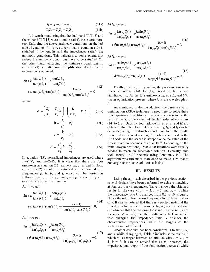
several designs have been performed to achieve matching at four arbitrary frequencies. Table 1 shows the obtained results for the case with u1 = 2, u2 = 3, and u3 = 4, while the impedance ratio k is changed from 0.5 to 10. Figure 2 shows the return loss versus frequency for different values of k. It can be noticed that there is a perfect match at the four design frequencies. From the figure, as expected, one can observe that the response for k and its inverse 1/k are the same. Moreover, from the results in Table 1, we notice that changing the impedance ratio k changes the characteristic impedances, while the lengths of the sections are not affected.
Another case that has been considered is to fix u2, u3 and k, while changing u1. Table 2 includes some results in which u1 is changed between 1.4 and 2.6, with u2 = 3, u3 = 4, k = 2. It can be noticed that as u1 increases, the impedance and length of the first section decrease, while
383 ACES JOURNAL, VOL. 22, NO. 3, NOVEMBER 2007
0 0.5 1 1.5 2 2.5 3 3.5 4 4.5 5-70
-60
-50
-40
-30
-20
-10
0
Frequency (GHz)
Ret
urn
loss
(dB
)
u2 = 2.8, 3.2, 3.6
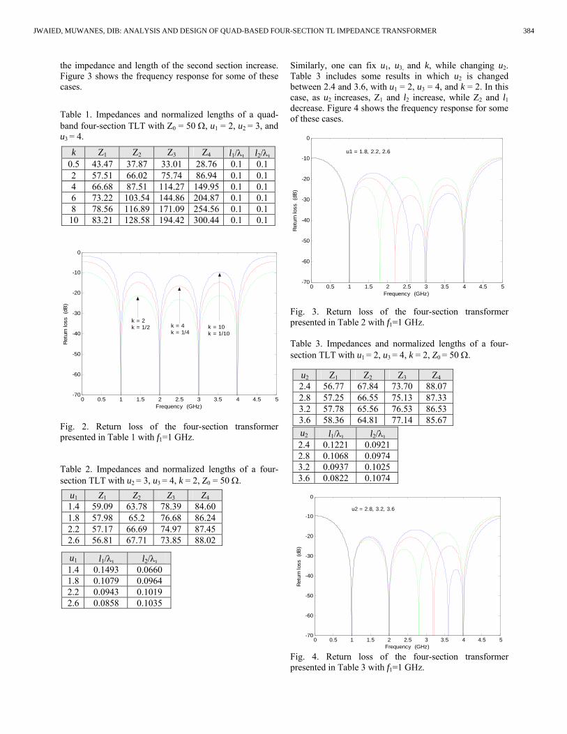
the impedance and length of the second section increase. Figure 3 shows the frequency response for some of these cases.
Table 1. Impedances and normalized lengths of a quad-band four-section TLT with Z0 = 50 Ω, u1 = 2, u2 = 3, and u3 = 4.
Fig. 2. Return loss of the four-section transformer presented in Table 1 with f1=1 GHz. Table 2. Impedances and normalized lengths of a four-section TLT with u2 = 3, u3 = 4, k = 2, Z0 = 50 Ω.
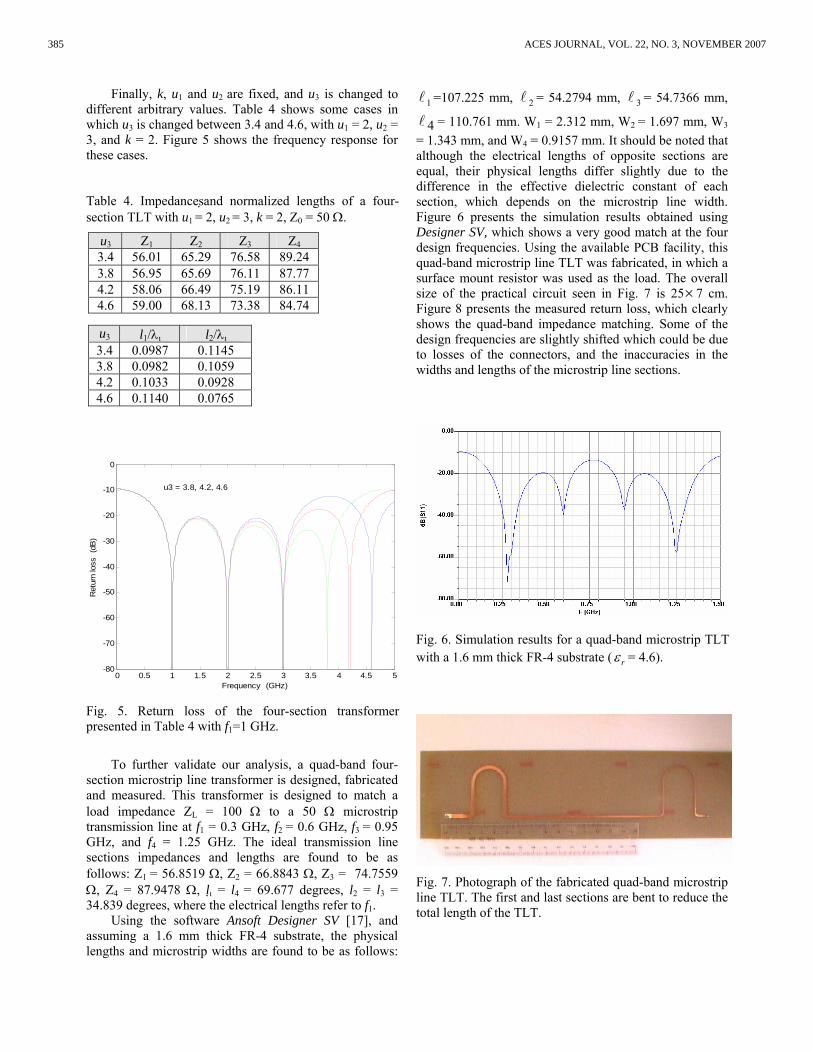
Similarly, one can fix u1, u3, and k, while changing u2. Table 3 includes some results in which u2 is changed between 2.4 and 3.6, with u1 = 2, u3 = 4, and k = 2. In this case, as u2 increases, Z1 and l2 increase, while Z2 and l1 decrease. Figure 4 shows the frequency response for some of these cases.
0 0.5 1 1.5 2 2.5 3 3.5 4 4.5 5-70
-60
-50
-40
-30
-20
-10
0
Frequency (GHz)R
etur
n lo
ss (
dB)
u1 = 1.8, 2.2, 2.6
Fig. 3. Return loss of the four-section transformer presented in Table 2 with f1=1 GHz. Table 3. Impedances and normalized lengths of a four-section TLT with u1 = 2, u3 = 4, k = 2, Z0 = 50 Ω.
Fig. 4. Return loss of the four-section transformer presented in Table 3 with f1=1 GHz.
k Z1 Z2 Z3 Z4 l1/λ l2/λ 0.5 43.47 37.87 33.01 28.76 0.1 0.1 2 57.51 66.02 75.74 86.94 0.1 0.1 4 66.68 87.51 114.27 149.95 0.1 0.1 6 73.22 103.54 144.86 204.87 0.1 0.1 8 78.56 116.89 171.09 254.56 0.1 0.1
10 83.21 128.58 194.42 300.44 0.1 0.1
u1 Z1 Z2 Z3 Z4 1.4 59.09 63.78 78.39 84.60 1.8 57.98 65.2 76.68 86.24 2.2 57.17 66.69 74.97 87.45 2.6 56.81 67.71 73.85 88.02
u2 Z1 Z2 Z3 Z4 2.4 56.77 67.84 73.70 88.07 2.8 57.25 66.55 75.13 87.33 3.2 57.78 65.56 76.53 86.53 3.6 58.36 64.81 77.14 85.67 u2 l1/λ l2/λ 2.4 0.1221 0.0921 2.8 0.1068 0.0974 3.2 0.0937 0.1025 3.6 0.0822 0.1074
u1 l1/λ l2/λ 1.4 0.1493 0.0660 1.8 0.1079 0.0964 2.2 0.0943 0.1019 2.6 0.0858 0.1035
0 0.5 1 1.5 2 2.5 3 3.5 4 4.5 5-70
-60
-50
-40
-30
-20
-10
0
Frequency (GHz)
Ret
urn
loss
(dB
)
k = 2 k = 1/2 k = 4
k = 1/4 k = 10 k = 1/10
384JWAIED, MUWANES, DIB: ANALYSIS AND DESIGN OF QUAD-BASED FOUR-SECTION TL IMPEDANCE TRANSFORMER
Finally, k, u1 and u2 are fixed, and u3 is changed to different arbitrary values. Table 4 shows some cases in which u3 is changed between 3.4 and 4.6, with u1 = 2, u2 = 3, and k = 2. Figure 5 shows the frequency response for these cases. Table 4. Impedancesand normalized lengths of a four-section TLT with u1 = 2, u2 = 3, k = 2, Z0 = 50 Ω.
0 0.5 1 1.5 2 2.5 3 3.5 4 4.5 5-80
-70
-60
-50
-40
-30
-20
-10
0
Frequency (GHz)
Ret
urn
loss
(dB
)
u3 = 3.8, 4.2, 4.6
Fig. 5. Return loss of the four-section transformer presented in Table 4 with f1=1 GHz.
To further validate our analysis, a quad-band four-section microstrip line transformer is designed, fabricated and measured. This transformer is designed to match a load impedance ZL = 100 Ω to a 50 Ω microstrip transmission line at f1 = 0.3 GHz, f2 = 0.6 GHz, f3 = 0.95 GHz, and f4 = 1.25 GHz. The ideal transmission line sections impedances and lengths are found to be as follows: Z1 = 56.8519 Ω, Z2 = 66.8843 Ω, Z3 = 74.7559 Ω, Z4 = 87.9478 Ω, l = l4 = 69.677 degrees, l2 = l3 = 34.839 degrees, where the electrical lengths refer to f1.
Using the software Ansoft Designer SV [17], and assuming a 1.6 mm thick FR-4 substrate, the physical lengths and microstrip widths are found to be as follows:
1 =107.225 mm, 2 = 54.2794 mm, 3 = 54.7366 mm,
4 = 110.761 mm. W1 = 2.312 mm, W2 = 1.697 mm, W3 = 1.343 mm, and W4 = 0.9157 mm. It should be noted that although the electrical lengths of opposite sections are equal, their physical lengths differ slightly due to the difference in the effective dielectric constant of each section, which depends on the microstrip line width. Figure 6 presents the simulation results obtained using Designer SV, which shows a very good match at the four design frequencies. Using the available PCB facility, this quad-band microstrip line TLT was fabricated, in which a surface mount resistor was used as the load. The overall size of the practical circuit seen in Fig. 7 is 25×7 cm. Figure 8 presents the measured return loss, which clearly shows the quad-band impedance matching. Some of the design frequencies are slightly shifted which could be due to losses of the connectors, and the inaccuracies in the widths and lengths of the microstrip line sections.
Fig. 6. Simulation results for a quad-band microstrip TLT with a 1.6 mm thick FR-4 substrate ( rε = 4.6).
Fig. 7. Photograph of the fabricated quad-band microstrip line TLT. The first and last sections are bent to reduce the total length of the TLT.
u3 Z1 Z2 Z3 Z4 3.4 56.01 65.29 76.58 89.24 3.8 56.95 65.69 76.11 87.77 4.2 58.06 66.49 75.19 86.11 4.6 59.00 68.13 73.38 84.74
u3 l1/λ l2/λ 3.4 0.0987 0.1145 3.8 0.0982 0.1059 4.2 0.1033 0.0928 4.6 0.1140 0.0765
385 ACES JOURNAL, VOL. 22, NO. 3, NOVEMBER 2007
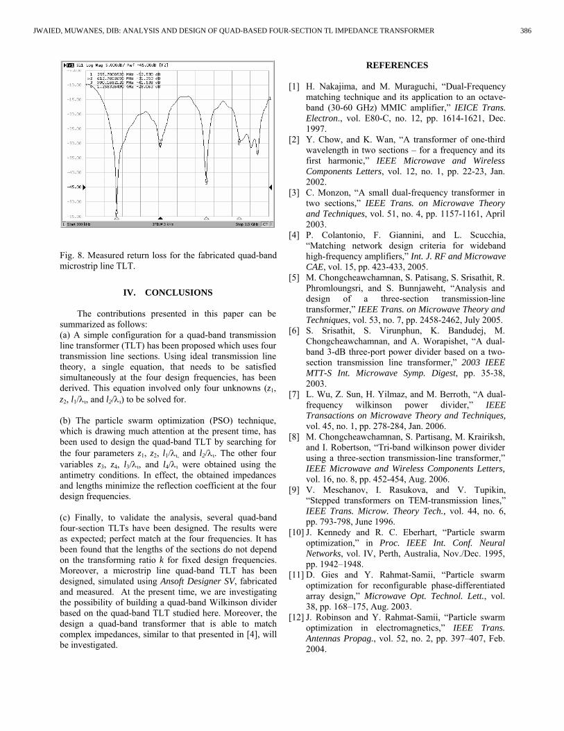
Fig. 8. Measured return loss for the fabricated quad-band microstrip line TLT.
IV. CONCLUSIONS
The contributions presented in this paper can be summarized as follows: (a) A simple configuration for a quad-band transmission line transformer (TLT) has been proposed which uses four transmission line sections. Using ideal transmission line theory, a single equation, that needs to be satisfied simultaneously at the four design frequencies, has been derived. This equation involved only four unknowns (z1, z2, l1/λ, and l2/λ) to be solved for. (b) The particle swarm optimization (PSO) technique, which is drawing much attention at the present time, has been used to design the quad-band TLT by searching for the four parameters z1, z2, l1/λ, and l2/λ. The other four variables z3, z4, l3/λ, and l4/λ were obtained using the antimetry conditions. In effect, the obtained impedances and lengths minimize the reflection coefficient at the four design frequencies. (c) Finally, to validate the analysis, several quad-band four-section TLTs have been designed. The results were as expected; perfect match at the four frequencies. It has been found that the lengths of the sections do not depend on the transforming ratio k for fixed design frequencies. Moreover, a microstrip line quad-band TLT has been designed, simulated using Ansoft Designer SV, fabricated and measured. At the present time, we are investigating the possibility of building a quad-band Wilkinson divider based on the quad-band TLT studied here. Moreover, the design a quad-band transformer that is able to match complex impedances, similar to that presented in [4], will be investigated.
REFERENCES
[1] H. Nakajima, and M. Muraguchi, “Dual-Frequency matching technique and its application to an octave-band (30-60 GHz) MMIC amplifier,” IEICE Trans. Electron., vol. E80-C, no. 12, pp. 1614-1621, Dec. 1997.
[2] Y. Chow, and K. Wan, “A transformer of one-third wavelength in two sections – for a frequency and its first harmonic,” IEEE Microwave and Wireless Components Letters, vol. 12, no. 1, pp. 22-23, Jan. 2002.
[3] C. Monzon, “A small dual-frequency transformer in two sections,” IEEE Trans. on Microwave Theory and Techniques, vol. 51, no. 4, pp. 1157-1161, April 2003.
[4] P. Colantonio, F. Giannini, and L. Scucchia, “Matching network design criteria for wideband high-frequency amplifiers,” Int. J. RF and Microwave CAE, vol. 15, pp. 423-433, 2005.
[5] M. Chongcheawchamnan, S. Patisang, S. Srisathit, R. Phromloungsri, and S. Bunnjaweht, “Analysis and design of a three-section transmission-line transformer,” IEEE Trans. on Microwave Theory and Techniques, vol. 53, no. 7, pp. 2458-2462, July 2005.
[6] S. Srisathit, S. Virunphun, K. Bandudej, M. Chongcheawchamnan, and A. Worapishet, “A dual-band 3-dB three-port power divider based on a two-section transmission line transformer,” 2003 IEEE MTT-S Int. Microwave Symp. Digest, pp. 35-38, 2003.
[7] L. Wu, Z. Sun, H. Yilmaz, and M. Berroth, “A dual-frequency wilkinson power divider,” IEEE Transactions on Microwave Theory and Techniques, vol. 45, no. 1, pp. 278-284, Jan. 2006.
[8] M. Chongcheawchamnan, S. Partisang, M. Krairiksh, and I. Robertson, “Tri-band wilkinson power divider using a three-section transmission-line transformer,” IEEE Microwave and Wireless Components Letters, vol. 16, no. 8, pp. 452-454, Aug. 2006.
[9] V. Meschanov, I. Rasukova, and V. Tupikin, “Stepped transformers on TEM-transmission lines,” IEEE Trans. Microw. Theory Tech., vol. 44, no. 6, pp. 793-798, June 1996.
[10] J. Kennedy and R. C. Eberhart, “Particle swarm optimization,” in Proc. IEEE Int. Conf. Neural Networks, vol. IV, Perth, Australia, Nov./Dec. 1995, pp. 1942–1948.
[11] D. Gies and Y. Rahmat-Samii, “Particle swarm optimization for reconfigurable phase-differentiated array design,” Microwave Opt. Technol. Lett., vol. 38, pp. 168–175, Aug. 2003.
[12] J. Robinson and Y. Rahmat-Samii, “Particle swarm optimization in electromagnetics,” IEEE Trans. Antennas Propag., vol. 52, no. 2, pp. 397–407, Feb. 2004.
386JWAIED, MUWANES, DIB: ANALYSIS AND DESIGN OF QUAD-BASED FOUR-SECTION TL IMPEDANCE TRANSFORMER
[13] M. Khodier and C. Christodoulou, “Linear array geometry synthesis with minimum sidelobe level and null control using particle swarm optimization,” IEEE Trans. Antennas Propagat., vol. 53, no. 8, pp. 2674-2679, August 2005.
[14] J. Ababneh, M. Khodier, and N. Dib, “Synthesis of interdigital capacitors based on particle swarm optimization and artificial neural networks,” International Journal of RF and Microwave Computer-Aided Engineering, vol. 16, pp. 322-330, July 2006.
[15] N. Dib and J. Ababneh, “Physical modeling and particle swarm design of coplanar waveguide square spiral inductor,” accepted for publication in Int. J. of Modeling and Simulation, to appear beginning of 2008.
[16] Y. Najjar, M. Moneer, and N. Dib, “Design of optimum gain pyramidal horn with improved formulas using particle swarm optimization,” accepted for publication in International Journal of RF and Microwave Computer-Aided Engineering, to appear in July 2007 issue.
[17] Available at www.ansoft.com.
Hussam Jwaied was born in Ajloun, Jordan, on July 9, 1984. He received his B. Sc. degree in telecommunication and electronics engineering from Jordan University of Science and Technology, Irbid, Jordan, in 2007. His research interests include RF and microwave
integrated circuits.
Firas Muwanes was born in Zarqa, Jordan on June 5, 1984. He received the B. Sc. degree in telecommunication and electronics engineering from Jordan University of Science and Technology, Irbid, Jordan, in 2007. His current research interests include RF and microwave integrated circuits.
Nihad Dib obtained his B. Sc. and M. Sc. in EE from Kuwait University in 1985 and 1987, respectively. He obtained his Ph. D. in EE (major in Electromagnetics and Microwaves) in 1992 from University of Michigan, Ann Arbor. Then, he worked as an assistant research scientist in the radiation laboratory at the same
school. In Sep. 1995, he joined the EE department at Jordan University of Science and Technology (JUST) as an assistant professor, and became a full professor in Aug. 2006. In 2002-2003, he was a senior research engineer with Ansoft Corporation, USA. His research interests are in computational electromagnetics and modeling of passive microwave components and circuits.
387 ACES JOURNAL, VOL. 22, NO. 3, NOVEMBER 2007
2007 INSTITUTIONAL MEMBERS
AUSTRALIAN DEFENCE LIBRARY Northcott Drive Canberra, A.C.T. 2600 Australia BAE SYSTEMS W. Hanningfield Road Technology Center Library Great Baddow, Chelmsford UK CM2 8HN BEIJING BOOK COMPANY, INC 701 E Lindon Ave. Linden, NJ 07036-2495 DARTMOUTH COLL-FELDBERG LIB 6193 Murdough Center Hanover, NH 03755-3560 DSTO-DSTORL EDINBURGH Jets AU/33851-99, PO Box 562 Milsons Point, NSW Australia 1565 DTIC-OCP/LIBRARY 8725 John J. Kingman Rd. Ste 0944 Ft. Belvoir, VA 22060-6218 ELLEDIEMME SRL C.P. 69 Poste S. Silvestro Roma, Italy 00187 ELSEVIER Bibliographic Databases PO Box 2227 Amsterdam, Netherlands 1000 CE ENGINEERING INFORMATION, INC PO Box 543 Amsterdam, Netherlands 1000 Am ETSE TELECOMUNICACION Biblioteca, Campus Lagoas Vigo, 36200 Spain FGAN-FHR Neuenahrerstrasse 20 Wachtberg, Germany 53343 FLORIDA INTERNATIONAL UNIV 10555 W. Flagler Street Miami, FL 33174
GEORGIA TECH LIBRARY 225 North Avenue, NW Atlanta, GA 30332-0001 HANYANG UNIVERSITY Paiknam Academic Info. Ctr Library 17 Haengdang-Dong Seongdong-Ku Seoul, South Korea 133-791 HRL LABS, RESEARCH LIBRARY 3011 Malibu Canyon Malibu, CA 90265 IEE INSPEC/Acquisitions Section Michael Faraday House 6 Hills Way Stevenage, Herts UK SG1 2AY INSTITUTE FOR SCIENTIFIC INFO. Publication Processing Dept. 3501 Market St. Philadelphia, PA 19104-3302 IPS RADIO & SPACE SERVICES PO Box 1386 Haymarket NSW Australia 1240 ISRAEL AIRCRAFT INDUSTRIES Ben-Gurion Airport 70100 Israel LEMA-EPFL ELB-ECUBLEMS Lausanne, Switzerland CH-1020 LIBRARY – DRDC OTTAWA 3701 Carling Avenue Ottawa, Ontario, Canada K1A OZ4 LIBRARY of CONGRESS Reg. Of Copyrights Attn: 40T Deposits Washington DC, 20559 LINDA HALL LIBRARY 5109 Cherry Street Kansas City, MO 64110-2498 MISSISSIPPI STATE UNIV LIBRARY PO Box 9570Mississippi State, MS 39762
MIT LINCOLN LABORATORY Periodicals Library 244 Wood Street Lexington, MA 02420 NAVAL POSTGRADUATE SCHOOL Attn:J. Rozdal/411 Dyer Rd./ Rm 111 Monterey, CA 93943-5101 NAVAL RESEARCH LABORATORY Code 3516 4555 Overlook Avenue SW Washington, DC 20375-5334 NDL KAGAKU C/0 KWE-ACCESS PO Box 300613 (JFK A/P) Jamaica, NY 11430-0613 OHIO STATE UNIVERSITY 1320 Kinnear Road Columbus, OH 43212 OVIEDO LIBRARY PO BOX 830679 Birmingham, AL 35283 PENN STATE UNIVERSITY 126 Paterno Library University Park, PA 16802-1808 PHILIPS RESEARCH LABORATORY Cross Oak Lane, Stella Cox Salfords, Redhill UK RH1 5HA RENTON TECH LIBRARY/BOEING PO BOX 3707 SEATTLE, WA 98124-2207 SOUTHWEST RESEARCH INSTITUTE 6220 Culebra Road San Antonio, TX 78238 SWETS INFORMATION SERVICES 160 Ninth Avenue, Suite A Runnemede, NJ 08078 TECHNISCHE UNIV. DELFT Mekelweg 4, Delft, Holland, 2628 CD Netherlands
TELSTRA TRL/M2/770 Blackburn Road Clayton, Victoria, Australia 3168 TIB & UNIV. BIB. HANNOVER DE/5100/G1/0001 Welfengarten 1B Hannover, Germany 30167 TU DARMSTADT Schlossgartenstrasse 8 Darmstadt, Hessen Germany D-64289 UNIV OF CENTRAL FLORIDA LIB. 4000 Central Florida Boulevard Orlando, FL 32816-8005 UNIV OF COLORADO LIBRARY Campus Box 184 Boulder, CO 80309-0184 UNIVERSITY OF MISSISSIPPI John Davis Williams Library PO Box 1848 University, MS 38677-1848 UNIV OF MISSOURI-ROLLA LIB. 1870 Miner Circle Rolla, MO 65409-0001 UNIV POL DE CARTAGENE PO Box 830470 Birmingham, AL 35283 USAE ENG. RES. & DEV. CENTER Attn: Library/Journals 72 Lyme Road Hanover, NH 03755-1290

ACES COPYRIGHT FORM
This form is intended for original, previously unpublished manuscripts submitted to ACES periodicals and conference publications. The signed form, appropriately completed, MUST ACCOMPANY any paper in order to be published by ACES. PLEASE READ REVERSE SIDE OF THIS FORM FOR FURTHER DETAILS. TITLE OF PAPER: RETURN FORM TO:
Dr. Atef Z. Elsherbeni University of Mississippi Dept. of Electrical Engineering
AUTHORS(S) Anderson Hall Box 13 PUBLICATION TITLE/DATE: University, MS 38677 USA
PART A - COPYRIGHT TRANSFER FORM (NOTE: Company or other forms may not be substituted for this form. U.S. Government employees whose work is not subject to copyright may so certify by signing Part B below. Authors whose work is subject to Crown Copyright may sign Part C overleaf). The undersigned, desiring to publish the above paper in a publication of ACES, hereby transfer their copyrights in the above paper to The Applied Computational Electromagnetics Society (ACES). The undersigned hereby represents and warrants that the paper is original and that he/she is the author of the paper or otherwise has the power and authority to make and execute this assignment. Returned Rights: In return for these rights, ACES hereby grants to the above authors, and the employers for whom the work was performed, royalty-free permission to:
1. Retain all proprietary rights other than copyright, such as patent rights. 2. Reuse all or portions of the above paper in other works. 3. Reproduce, or have reproduced, the above paper for the author’s personal use or for internal company use provided that (a) the source and
ACES copyright are indicated, (b) the copies are not used in a way that implies ACES endorsement of a product or service of an employer, and (c) the copies per se are not offered for sale.
4. Make limited distribution of all or portions of the above paper prior to publication. 5. In the case of work performed under U.S. Government contract, ACES grants the U.S. Government royalty-free permission to reproduce all
or portions of the above paper, and to authorize others to do so, for U.S. Government purposes only. ACES Obligations: In exercising its rights under copyright, ACES will make all reasonable efforts to act in the interests of the authors and employers as well as in its own interest. In particular, ACES REQUIRES that: 1. The consent of the first-named author be sought as a condition in granting re-publication permission to others. 2. The consent of the undersigned employer be obtained as a condition in granting permission to others to reuse all or portions of the paper for promotion or marketing purposes. In the event the above paper is not accepted and published by ACES or is withdrawn by the author(s) before acceptance by ACES, this agreement becomes null and void. AUTHORIZED SIGNATURE TITLE (IF NOT AUTHOR) EMPLOYER FOR WHOM WORK WAS PERFORMED DATE FORM SIGNED
Part B - U.S. GOVERNMENT EMPLOYEE CERTIFICATION
(NOTE: if your work was performed under Government contract but you are not a Government employee, sign transfer form above and see item 5 under Returned Rights). This certifies that all authors of the above paper are employees of the U.S. Government and performed this work as part of their employment and that the paper is therefor not subject to U.S. copyright protection.
AUTHORIZED SIGNATURE TITLE (IF NOT AUTHOR) NAME OF GOVERNMENT ORGANIZATION DATE FORM SIGNED

PART C - CROWN COPYRIGHT
(NOTE: ACES recognizes and will honor Crown Copyright as it does U.S. Copyright. It is understood that, in asserting Crown Copyright, ACES in no way diminishes its rights as publisher. Sign only if ALL authors are subject to Crown Copyright). This certifies that all authors of the above Paper are subject to Crown Copyright. (Appropriate documentation and instructions regarding form of Crown Copyright notice may be attached). AUTHORIZED SIGNATURE TITLE OF SIGNEE NAME OF GOVERNMENT BRANCH DATE FORM SIGNED
Information to Authors
ACES POLICY ACES distributes its technical publications throughout the world, and it may be necessary to translate and abstract its publications, and articles contained therein, for inclusion in various compendiums and similar publications, etc. When an article is submitted for publication by ACES, acceptance of the article implies that ACES has the rights to do all of the things it normally does with such an article. In connection with its publishing activities, it is the policy of ACES to own the copyrights in its technical publications, and to the contributions contained therein, in order to protect the interests of ACES, its authors and their employers, and at the same time to facilitate the appropriate re-use of this material by others. The new United States copyright law requires that the transfer of copyrights in each contribution from the author to ACES be confirmed in writing. It is therefore necessary that you execute either Part A-Copyright Transfer Form or Part B-U.S. Government Employee Certification or Part C-Crown Copyright on this sheet and return it to the Managing Editor (or person who supplied this sheet) as promptly as possible. CLEARANCE OF PAPERS ACES must of necessity assume that materials presented at its meetings or submitted to its publications is properly available for general dissemination to the audiences these activities are organized to serve. It is the responsibility of the authors, not ACES, to determine whether disclosure of their material requires the prior consent of other parties and if so, to obtain it. Furthermore, ACES must assume that, if an author uses within his/her article previously published and/or copyrighted material that permission has been obtained for such use and that any required credit lines, copyright notices, etc. are duly noted. AUTHOR/COMPANY RIGHTS If you are employed and you prepared your paper as a part of your job, the rights to your paper initially rest with your employer. In that case, when you sign the copyright form, we assume you are authorized to do so by your employer and that your employer has consented to all of the terms and conditions of this form. If not, it should be signed by someone so authorized.
NOTE RE RETURNED RIGHTS: Just as ACES now requires a signed copyright transfer form in order to do “business as usual”, it is the intent of this form to return rights to the author and employer so that they too may do “business as usual”. If further clarification is required, please contact: The Managing Editor, R. W. Adler, Naval Postgraduate School, Code EC/AB, Monterey, CA, 93943, USA (831)656-2352. Please note that, although authors are permitted to re-use all or portions of their ACES copyrighted material in other works, this does not include granting third party requests for reprinting, republishing, or other types of re-use. JOINT AUTHORSHIP For jointly authored papers, only one signature is required, but we assume all authors have been advised and have consented to the terms of this form. U.S. GOVERNMENT EMPLOYEES Authors who are U.S. Government employees are not required to sign the Copyright Transfer Form (Part A), but any co-authors outside the Government are. Part B of the form is to be used instead of Part A only if all authors are U.S. Government employees and prepared the paper as part of their job.
NOTE RE GOVERNMENT CONTRACT WORK: Authors whose work was performed under a U.S. Government contract but who are not Government employees are required so sign Part A-Copyright Transfer Form. However, item 5 of the form returns reproduction rights to the U. S. Government when required, even though ACES copyright policy is in effect with respect to the reuse of material by the general public. January 2002
APPLIED COMPUTATIONAL ELECTROMAGNETICS SOCIETY JOURNAL http://aces.ee.olemiss.edu
INFORMATION FOR AUTHORS
PUBLICATION CRITERIA Each paper is required to manifest some relation to applied computational electromagnetics. Papers may address general issues in applied computational electromagnetics, or they may focus on specific applications, techniques, codes, or computational issues. While the following list is not exhaustive, each paper will generally relate to at least one of these areas: 1. Code validation. This is done using internal checks or
experimental, analytical or other computational data. Measured data of potential utility to code validation efforts will also be considered for publication.
2. Code performance analysis. This usually involves
identification of numerical accuracy or other limitations, solution convergence, numerical and physical modeling error, and parameter tradeoffs. However, it is also permissible to address issues such as ease-of-use, set-up time, run time, special outputs, or other special features.
3. Computational studies of basic physics. This involves
using a code, algorithm, or computational technique to simulate reality in such a way that better, or new physical insight or understanding, is achieved.
4. New computational techniques or new applications for
existing computational techniques or codes. 5. “Tricks of the trade” in selecting and applying codes
and techniques. 6. New codes, algorithms, code enhancement, and code
fixes. This category is self-explanatory, but includes significant changes to existing codes, such as applicability extensions, algorithm optimization, problem correction, limitation removal, or other performance improvement. Note: Code (or algorithm) capability descriptions are not acceptable, unless they contain sufficient technical material to justify consideration.
7. Code input/output issues. This normally involves
innovations in input (such as input geometry standardization, automatic mesh generation, or computer-aided design) or in output (whether it be tabular, graphical, statistical, Fourier-transformed, or otherwise signal-processed). Material dealing with input/output database management, output interpretation, or other input/output issues will also be considered for publication.
8. Computer hardware issues. This is the category for
analysis of hardware capabilities and limitations of various types of electromagnetics computational requirements. Vector and parallel computational techniques and implementation are of particular interest.
Applications of interest include, but are not limited to, antennas (and their electromagnetic environments), networks, static fields, radar cross section, inverse scattering, shielding, radiation hazards, biological effects, biomedical applications, electromagnetic pulse (EMP), electromagnetic interference (EMI), electromagnetic compatibility (EMC), power transmission, charge transport, dielectric, magnetic and nonlinear materials, microwave components, MEMS, RFID, and MMIC technologies, remote sensing and geometrical and physical optics, radar and communications systems, sensors, fiber optics, plasmas, particle accelerators, generators and motors, electromagnetic wave propagation, non-destructive evaluation, eddy currents, and inverse scattering. Techniques of interest include but not limited to frequency-domain and time-domain techniques, integral equation and differential equation techniques, diffraction theories, physical and geometrical optics, method of moments, finite differences and finite element techniques, transmission line method, modal expansions, perturbation methods, and hybrid methods. Where possible and appropriate, authors are required to provide statements of quantitative accuracy for measured and/or computed data. This issue is discussed in “Accuracy & Publication: Requiring, quantitative accuracy statements to accompany data,” by E. K. Miller, ACES Newsletter, Vol. 9, No. 3, pp. 23-29, 1994, ISBN 1056-9170. SUBMITTAL PROCEDURE All submissions should be uploaded to ACES server through ACES web site (http://aces.ee.olemiss.edu) by using the upload button, journal section. Only pdf files are accepted for submission. The file size should not be larger than 5MB, otherwise permission from the Editor-in-Chief should be obtained first. Automated acknowledgment of the electronic submission, after the upload process is successfully completed, will be sent to the corresponding author only. It is the responsibility of the corresponding author to keep the remaining authors, if applicable, informed. Email submission is not accepted and will not be processed. PAPER FORMAT (INITIAL SUBMISSION) The preferred format for initial submission manuscripts is 12 point Times Roman font, single line spacing and single column format, with 1 inch for top, bottom, left, and right margins. Manuscripts should be prepared for standard 8.5x11 inch paper. EDITORIAL REVIEW In order to ensure an appropriate level of quality control, papers are peer reviewed. They are reviewed both for
technical correctness and for adherence to the listed guidelines regarding information content and format. PAPER FORMAT (FINAL SUBMISSION) Only camera-ready electronic files are accepted for publication. The term “camera-ready” means that the material is neat, legible, reproducible, and in accordance with the final version format listed below. The following requirements are in effect for the final version of an ACES Journal paper: 1. The paper title should not be placed on a separate page.
The title, author(s), abstract, and (space permitting) beginning of the paper itself should all be on the first page. The title, author(s), and author affiliations should be centered (center-justified) on the first page. The title should be of font size 16 and bolded, the author names should be of font size 12 and bolded, and the author affiliation should be of font size 12 (regular font, neither italic nor bolded).
2. An abstract is required. The abstract should be a brief
summary of the work described in the paper. It should state the computer codes, computational techniques, and applications discussed in the paper (as applicable) and should otherwise be usable by technical abstracting and indexing services. The word “Abstract” has to be placed at the left margin of the paper, and should be bolded and italic. It also should be followed by a hyphen () with the main text of the abstract starting on the same line.
3. All section titles have to be centered and all the title
letters should be written in caps. The section titles need to be numbered using roman numbering (I. II. ….)
4. Either British English or American English spellings
may be used, provided that each word is spelled consistently throughout the paper.
5. Internal consistency of references format should be
maintained. As a guideline for authors, we recommend that references be given using numerical numbering in the body of the paper (with numerical listing of all references at the end of the paper). The first letter of the authors’ first name should be listed followed by a period, which in turn, followed by the authors’ complete last name. Use a coma (,) to separate between the authors’ names. Titles of papers or articles should be in quotation marks (“ ”), followed by the title of journal, which should be in italic font. The journal volume (vol.), issue number (no.), page numbering (pp.), month and year of publication should come after the journal title in the sequence listed here.
6. Internal consistency shall also be maintained for other
elements of style, such as equation numbering. As a guideline for authors who have no other preference, we suggest that equation numbers be placed in parentheses at the right column margin.
7. The intent and meaning of all text must be clear. For authors who are not masters of the English language, the ACES Editorial Staff will provide assistance with grammar (subject to clarity of intent and meaning). However, this may delay the scheduled publication date.
8. Unused space should be minimized. Sections and
subsections should not normally begin on a new page. ACES reserves the right to edit any uploaded material, however, this is not generally done. It is the author(s) responsibility to provide acceptable camera-ready pdf files. Incompatible or incomplete pdf files will not be processed for publication, and authors will be requested to re-upload a revised acceptable version. COPYRIGHTS AND RELEASES Each primary author must sign a copyright form and obtain a release from his/her organization vesting the copyright with ACES. Copyright forms are available at ACES, web site (http://aces.ee.olemiss.edu). To shorten the review process time, the executed copyright form should be forwarded to the Editor-in-Chief immediately after the completion of the upload (electronic submission) process. Both the author and his/her organization are allowed to use the copyrighted material freely for their own private purposes. Permission is granted to quote short passages and reproduce figures and tables from and ACES Journal issue provided the source is cited. Copies of ACES Journal articles may be made in accordance with usage permitted by Sections 107 or 108 of the U.S. Copyright Law. This consent does not extend to other kinds of copying, such as for general distribution, for advertising or promotional purposes, for creating new collective works, or for resale. The reproduction of multiple copies and the use of articles or extracts for commercial purposes require the consent of the author and specific permission from ACES. Institutional members are allowed to copy any ACES Journal issue for their internal distribution only. PUBLICATION CHARGES All authors are allowed for 8 printed pages per paper without charge. Mandatory page charges of $75 a page apply to all pages in excess of 8 printed pages. Authors are entitled to one, free of charge, copy of the journal issue in which their paper was published. Additional reprints are available for a nominal fee by submitting a request to the managing editor or ACES Secretary. Authors are subject to fill out a one page over-page charge form and submit it online along with the copyright form before publication of their manuscript. ACES Journal is abstracted in INSPEC, in Engineering Index, DTIC, Science Citation Index Expanded, the Research Alert, and to Current Contents/Engineering, Computing & Technology.