applied geomorphology lecture noteslibvolume3.xyz/.../geomorphology/geomorphologynot… · ·...
TRANSCRIPT
Applied Geomorphology Lecture Notes
By David T. Allison
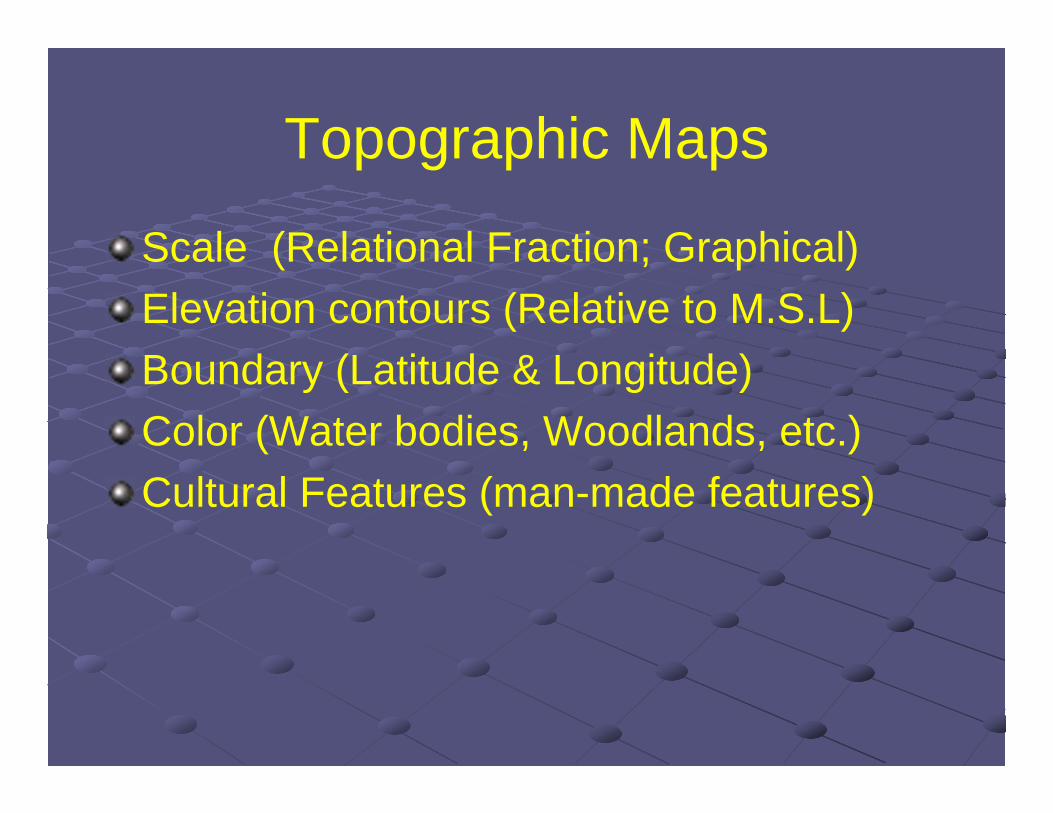
Topographic Maps
Scale (Relational Fraction; Graphical)Elevation contours (Relative to M.S.L)Boundary (Latitude & Longitude)Color (Water bodies, Woodlands, etc.)Cultural Features (man-made features)

Scale
Relational fraction 1:24,000 1 inch on the map = 24,000 inches in reality 1 inch on the map = 24,000 inches x 1 foot/12
inches 1 inch on the map = 2000 feet 1 inch on the map = 2000 feet x 1 mile/5280 ft 1 inch = 0.378 miles

Graphical Scale
Uses a graphical scale to indicate distances
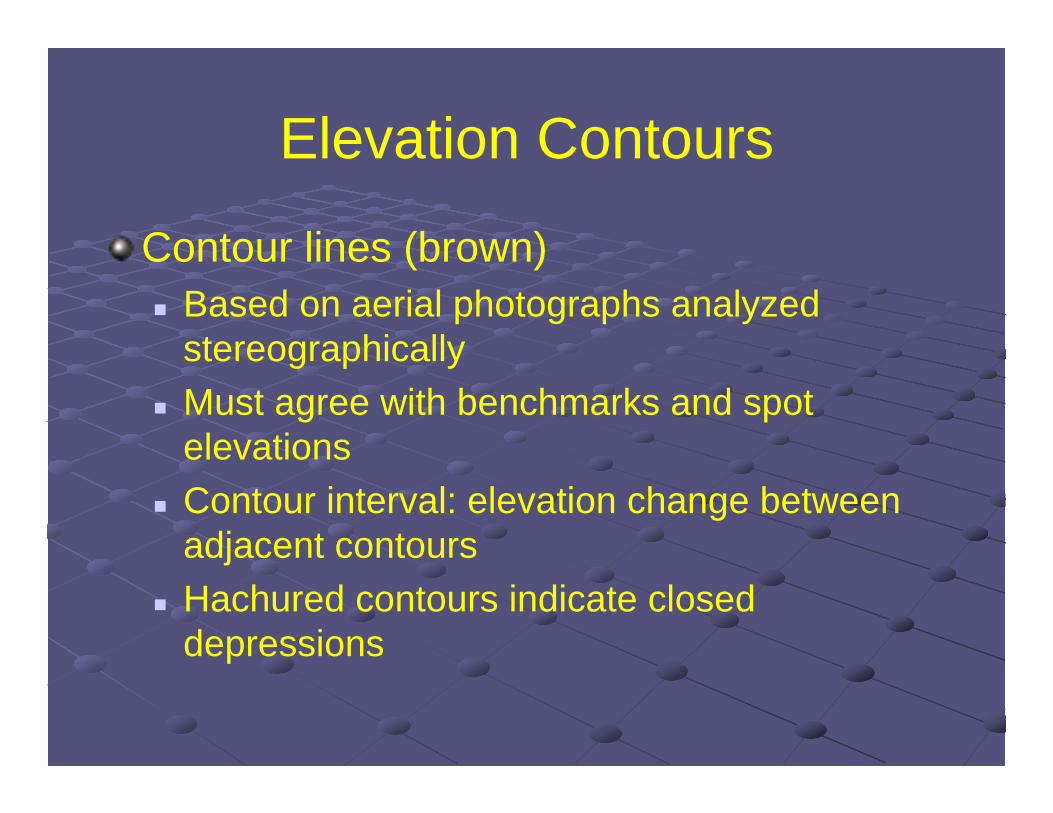
Elevation Contours
Contour lines (brown) Based on aerial photographs analyzed
stereographically Must agree with benchmarks and spot
elevations Contour interval: elevation change between
adjacent contours Hachured contours indicate closed
depressions
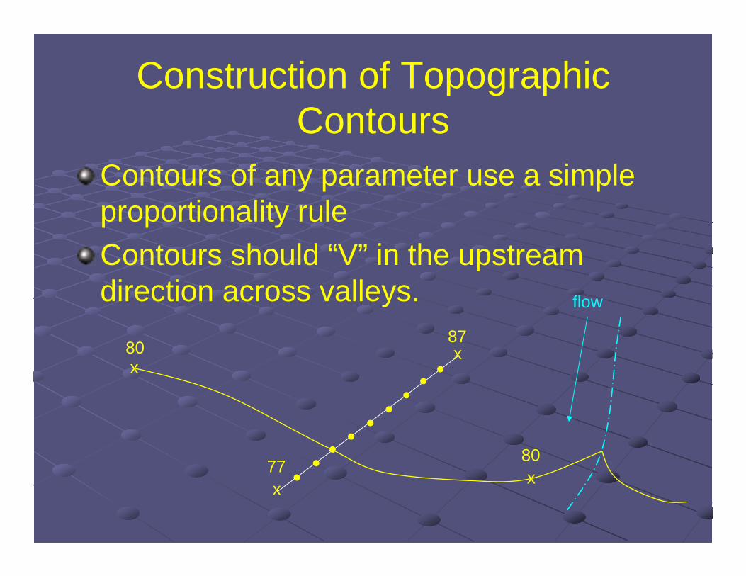
Construction of Topographic Contours
Contours of any parameter use a simple proportionality ruleContours should “V” in the upstream direction across valleys.
x
xx
x80
80
87
77
flow

Topographic contours in 3D
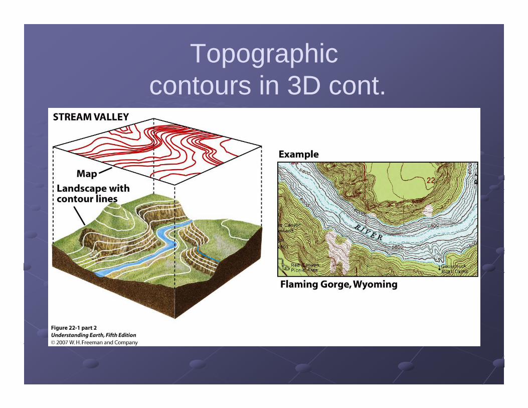
Topographiccontours in 3D cont.

Contours: can delineate geological contacts
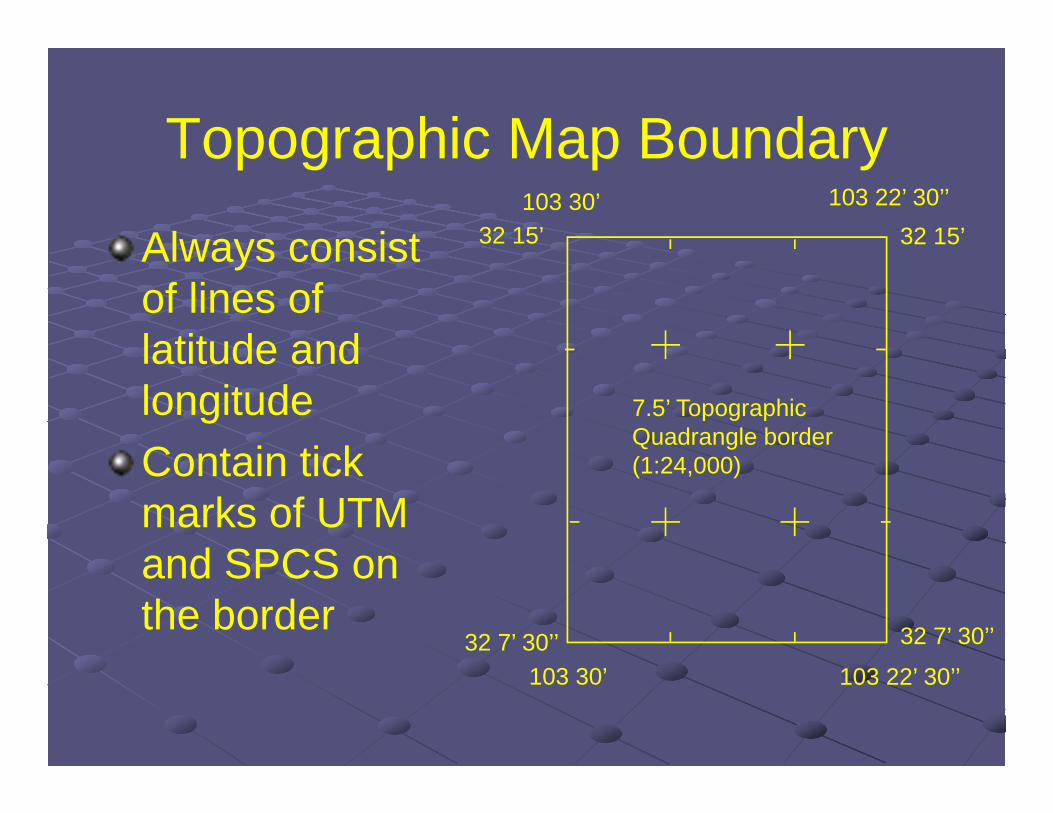
Topographic Map Boundary
Always consist of lines of latitude and longitudeContain tick marks of UTM and SPCS on the border 32 7’ 30’’
32 15’
103 22’ 30’’103 30’32 7’ 30’’
32 15’103 30’ 103 22’ 30’’
7.5’ TopographicQuadrangle border (1:24,000)
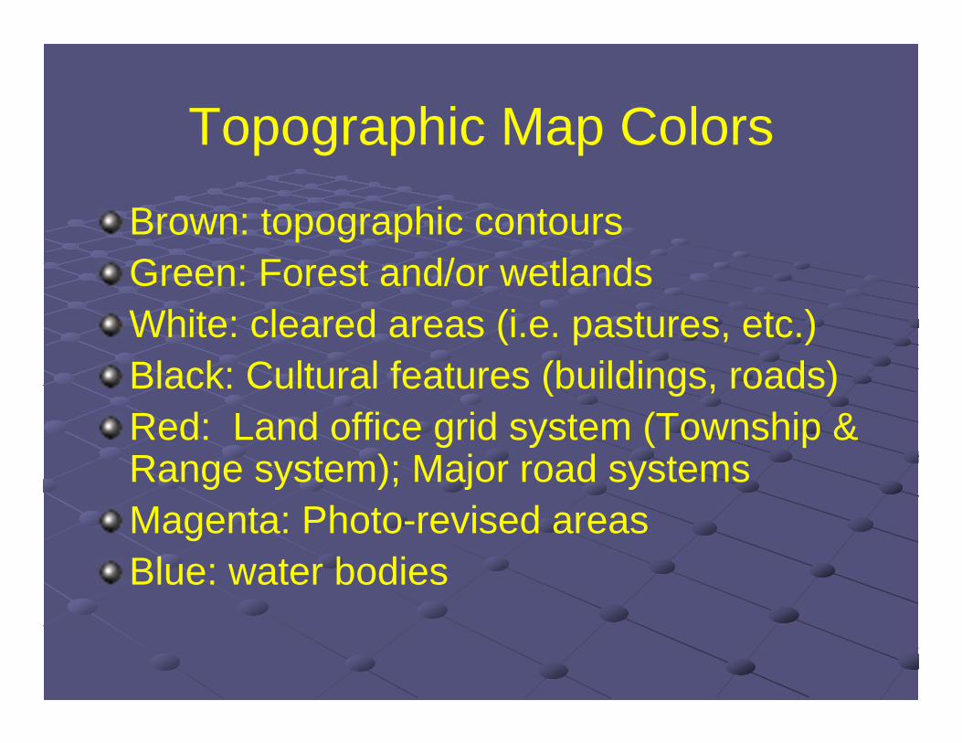
Topographic Map Colors
Brown: topographic contoursGreen: Forest and/or wetlandsWhite: cleared areas (i.e. pastures, etc.)Black: Cultural features (buildings, roads)Red: Land office grid system (Township & Range system); Major road systemsMagenta: Photo-revised areasBlue: water bodies

Topographic Map Examples
Map Coordinate Systems
Land Office Grid system (Township & Range)Universal Transverse Mercator (UTM)State Plane Coordinate System (SPCS)
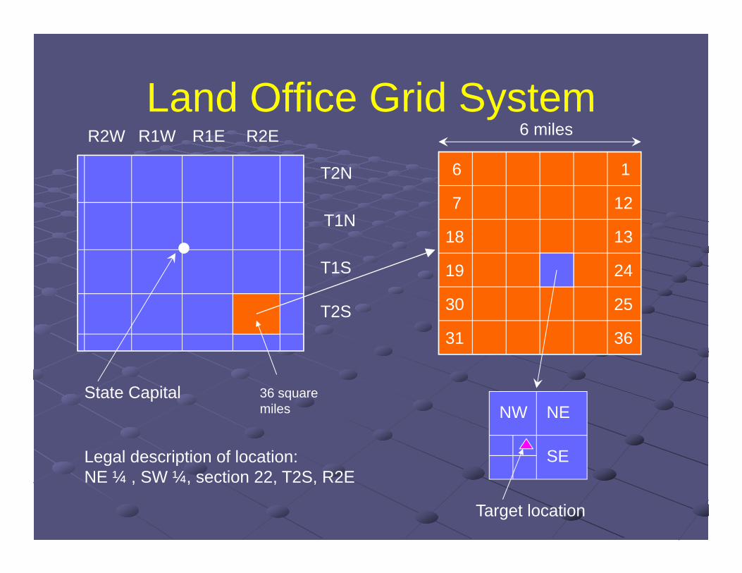
Land Office Grid System
T1N
T2N
T1S
T2S
R1E R2ER1WR2W
State Capital
6 1
7 12
1318
19 24
2530
31
36 squaremiles
36
6 miles
NW NE
SE
Target location
Legal description of location:NE ¼ , SW ¼, section 22, T2S, R2E
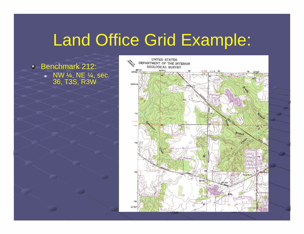
Land Office Grid Example:Benchmark 212: NW ¼, NE ¼, sec.
36, T3S, R3W