approved - emerson · america’s: +1 281 477 4100 (fax 477 2809) europe: +36 22 530 950 (fax +36...
TRANSCRIPT

Product data sheet
FieldQ
www.emerson.com/fieldqCopyright © Emerson. The information in this document is subject to change without notice. Updated data sheets can be obtained from our website www.emerson.com/fieldq or from your nearest Actuation Technologies Center: America’s: +1 281 477 4100 (fax 477 2809) Europe: +36 22 530 950 (fax +36 22 54 37 00) Asia Pacific: +65 6777 8211 (fax +65 626 80 028)
FieldQ
Integrated Control modulesQC41, QC42 and QC43
Features:
- Basic actuator functions for:
- Spring return applications, or- Double acting applications or,- Double acting Fail in Last Position applications.
- Suitable for all FieldQ actuator sizes.
- Available as "Weather Proof" for indoors or outdoors use and "Explosion Proof" for areas with a potential explosion hazard.
- The robust aluminum alloy enclosure (IP66 / NEMA4X rated), protects the IPT system, pneumatic components, the feedback switches and terminals and makes it suitable for indoor and outdoor use.
- The Explosion Proof version is available with ATEX / IECEx Ex d approval for use in Zone 1, 2, 21 and 22 and/or FM / CSA Explosion proof approval for use in Class I, Division 1.
- Various feedback switch options available.
- Non-Intrusive switch point adjustment of the feedback switches. Allows to adjust switch points without opening the Control Module.
- Lockable Control Module cover.
- All the control and feedback connections can be wired through one single entry to the Control Module.
- One larger entry (3/4"NPT) is available for larger multi-core cables on imperial units.
APPROVED
1.604.10 Rev. 0 Page 1 of 9October 2017

Product data sheet
FieldQ
www.emerson.com/fieldqCopyright © Emerson. The information in this document is subject to change without notice. Updated data sheets can be obtained from our website www.emerson.com/fieldq or from your nearest Actuation Technologies Center: America’s: +1 281 477 4100 (fax 477 2809) Europe: +36 22 530 950 (fax +36 22 54 37 00) Asia Pacific: +65 6777 8211 (fax +65 626 80 028)
FieldQ
Description:These FieldQ conventionally wired control modules are the next step for the integrated concept of valve automation. Next to the components for feedback switches, also all the pneumatic control components are located inside one module housing. Its compact and robust construction incorporates basic control and feedback functionality and is suitable for indoor and outdoor use.These modules are available with ATEX and IECEx certification for use in Zone 1, 2, 21 and 22, and additionally FM and CSA certified for use in Class I, Division 1.
Construction:The Control Module is mounted at the side of the basic actuator housing. Inside, wiring terminals are available for connecting control and feedback signals. Two cable entries are available. The pilot valves inside the control module are used to send the actuator to its open or closed position. One pneumatic connection is available to feed the control module.
General specifications:Material housing: Aluminium alloyOperating media: Air or inert gasses, filtered at 50µm
(for QC54 5µm)Pneumatic entry: Metric units: G1/4" Imperial units: 1/4”NPTElectrical connections: Pilot valve(s): 6 pole terminal strip. Switches: 6 pole terminal strip.Cable entries: Metric units: 2x M20x1.5 Imperial units: 1/2” and 3/4"NPTEnclosure: Rated IP66 - NEMA4XSwitch points: Factory set at 15° before each end of
travel (open and closed position).- Adjustable range: Between -3° to 15° and +75° to +93°
of the end position.Finish: Chromated, polyurethane based
coating.Temperature range: Depends on the switches inside
the module and or Hazardous Area approvals (See section "Position feedback"
Dimensions: Metric: See data sheet BQ1.603.08 Imperial/UNC: See data sheet BQ1.603.09 DIN 3337: See data sheet BQ1.603.10
Electrical safety requirements:Use : In- and outdoor.Altitude : Operating full power available up
to 2000 meter (6000 feet).Maximum relative : 80% for temperatures up to 31°C humidity (87.8°F) decreasing linearly
to 50% relative humidity at 40°C (104°F).
Mains supply : Up to ±10% of nominal voltagefluctuationOver voltage category : IIPollution degree : 2
(3 when the cover remains closed)
Control Module Type Label
Terminal compartment
Pilot valve terminals
Switch terminals
Option: Local Manual Control
Lockable Module cover
Option: Additional Local Manual Control for “Fail in Last Position”
Electrical entries:
3/4”NPT or M20
1/2”NPT or M20
Pneumatic connections:1/4”BSP or 1/4”NPT
Option: 1 or 2 speed control throttles
Non-Intrusive switch
point adjustment
Control module overview
1.604.10 Rev. 0 Page 2 of 9October 2017

Product data sheet
FieldQ
www.emerson.com/fieldqCopyright © Emerson. The information in this document is subject to change without notice. Updated data sheets can be obtained from our website www.emerson.com/fieldq or from your nearest Actuation Technologies Center: America’s: +1 281 477 4100 (fax 477 2809) Europe: +36 22 530 950 (fax +36 22 54 37 00) Asia Pacific: +65 6777 8211 (fax +65 626 80 028)
FieldQ
Pneumatic control
Pilot valve cartridge
Pilot valve terminals
Pneumatic cartridge
Pilot valve and pneumatic cartridge
Pneumatic control variationsThe Control Module contains all the necessary pneumatic components to control the actuator and control the incoming and outgoing airflow. Pneumatically the modules are available for three applications:1 Spring return or2 Double acting or3 Double Acting - "Fail-in-Last-Position".
To achieve these functions, each Control Module can be fitted with one or two pilot valves depending on the required functionality:
1 One pilot valve is default and suitable for normal operation of double acting or spring return actuators
2 Two pilot valves are required to achieve a "Fail-in-Last-Position" functionality on double acting actuators.
Table 1: Pilot valve specifications
Module Voltages Power Frequency
QC41 24VDC (±10%) 1W NA
QC42 115 VAC (±10%) 3VA 50/60Hz
QC43 230 VAC (±10%) 3VA 50/60Hz
One default pilot valve and wiring connections
Cable range: 0.33 - 2.5mm2 or 22-12AWG
Two pilot valves and wiring connections for Fail in Last Position
Pilot valve 1
Pilot valve 2
Cable range: 0.33 - 2.5mm2 or 22-12AWG
Pilot valve 1
FILP = Fail in Last PositionWiring diagram shown, is applicable for actuators with assembly code “CW”. For actuators with assembly code “CC” (reverse acting) the “Open” and “Closed” pilot valve connections are also reversed.
1.604.10 Rev. 0 Page 3 of 9October 2017

Product data sheet
FieldQ
www.emerson.com/fieldqCopyright © Emerson. The information in this document is subject to change without notice. Updated data sheets can be obtained from our website www.emerson.com/fieldq or from your nearest Actuation Technologies Center: America’s: +1 281 477 4100 (fax 477 2809) Europe: +36 22 530 950 (fax +36 22 54 37 00) Asia Pacific: +65 6777 8211 (fax +65 626 80 028)
FieldQ
Pneumatic componentsThe pneumatic components inside the module consist out of one or two pilot valves and a 3/2 spool valve or 5/2 bistable spool valve. The spool valves are pneumatically operated by the pilot valves. To assure trouble-free operation, the spool valves are equipped with big ports. This enables a large air flow and makes it less sensitive for contamination of the internals. The large air flow also fast cycle times and enables it to be utilized for the entire FieldQ actuator range.
Internal corrosion protection:The spring return models have standard a built in “Breather” function. During the spring stroke, the exhaust air from the center chamber (A-Port) is first fed to the spring chamber (B-port) preventing air from outside from being sucked into the spring chamber. This reduces the possibility of internal corrosion and maximizes the actuators’ working life.
Pneumatic options
Speed ControlThe FieldQ can be supplied with a Speed Control option. One throttle is required for Spring Return actuators and up to two for Double Acting actuators.The speed control throttle controls the air flow in and out of an air chamber and as such limits the speed of the “Opening” and “Closing” stroke simultaneously.
Silencers and vents The exhaust ports Ra and Rb on the module are shipped from the factory with transport protection.The module can be equipped with either silencers or vents.
Manual ControlFor commissioning, emergency or maintenance purposes, the FieldQ can be supplied with Manual Control options. These options can operate the actuator when there is air pressure available, but no control signal or power supply.- For normal operation the module should be fitted with
one Manual Control. - For Double Acting with a Fail-in-Last-Position function,
two Manual Control can be fitted.
Maximum Flow rates of Q-Series modulesThe maximum flow rates depends mainly on the flow ratesof the FieldQ XP modules. You can use Kv 0.28 (m3/h) or Cv value of 0.28 (US gall/min 1Psi) for approximate operating speed calculations.
A-port B-port
Ps
Pilot valve 1
3/2 Spool valve
Ra
Option: LMC
Option: Throttle 1
B-portA-port
PsRb
Pilot valve 1
5/2 Spool valve
Ra
Option: LMC
Option: Throttle 1
Option:Throttle 2
B-portA-port
Ps
Pilot valve 1
5/2 Spool valve
Pilot valve 2
Option: LMC 1 Option: LMC 2
Option:Throttle 1
Option:Throttle 2
Rb
Ra
Fail safe (spring return)
Double acting
Double Acting Fail in Last Position
1.604.10 Rev. 0 Page 4 of 9October 2017
Product data sheet
FieldQ
www.emerson.com/fieldqCopyright © Emerson. The information in this document is subject to change without notice. Updated data sheets can be obtained from our website www.emerson.com/fieldq or from your nearest Actuation Technologies Center: America’s: +1 281 477 4100 (fax 477 2809) Europe: +36 22 530 950 (fax +36 22 54 37 00) Asia Pacific: +65 6777 8211 (fax +65 626 80 028)
FieldQ
Position feedback
DO
NOT
OPEN WHEN ENERG
IZED
- WARNING! -
1
2
4
3
"Closed"
Switch point adjustment
"Open"
Switch point adjustment
Switch cartridges
Non-Intrusive switch point adjustment
Terminal strip position feedback switches
Switch cartridge
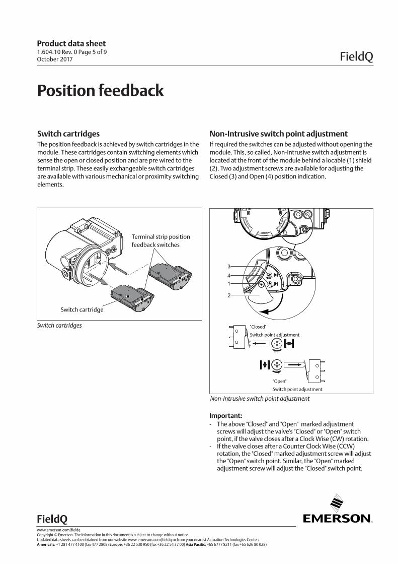
Switch cartridgesThe position feedback is achieved by switch cartridges in the module. These cartridges contain switching elements which sense the open or closed position and are pre wired to the terminal strip. These easily exchangeable switch cartridges are available with various mechanical or proximity switching elements.
Non-Intrusive switch point adjustmentIf required the switches can be adjusted without opening the module. This, so called, Non-Intrusive switch adjustment is located at the front of the module behind a locable (1) shield (2). Two adjustment screws are available for adjusting the Closed (3) and Open (4) position indication.
Important:- The above "Closed" and "Open" marked adjustment
screws will adjust the valve's "Closed" or "Open" switch point, if the valve closes after a Clock Wise (CW) rotation.
- If the valve closes after a Counter Clock Wise (CCW) rotation, the "Closed" marked adjustment screw will adjust the "Open" switch point. Similar, the "Open" marked adjustment screw will adjust the "Closed" switch point.
1.604.10 Rev. 0 Page 5 of 9October 2017
Product data sheet
FieldQ
www.emerson.com/fieldqCopyright © Emerson. The information in this document is subject to change without notice. Updated data sheets can be obtained from our website www.emerson.com/fieldq or from your nearest Actuation Technologies Center: America’s: +1 281 477 4100 (fax 477 2809) Europe: +36 22 530 950 (fax +36 22 54 37 00) Asia Pacific: +65 6777 8211 (fax +65 626 80 028)
FieldQ
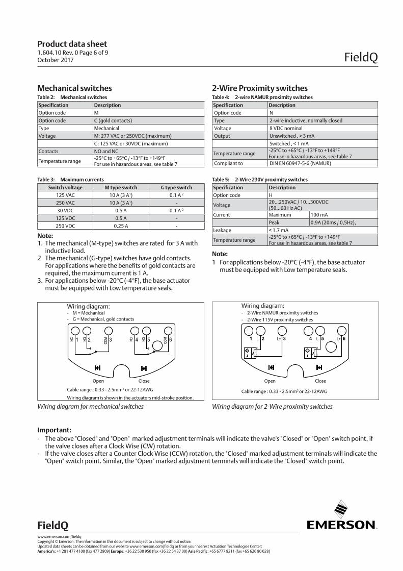
Mechanical switchesTable 2: Mechanical switches
Specification Description
Option code M
Option code G (gold contacts)
Type Mechanical
Voltage M: 277 VAC or 250VDC (maximum)
G: 125 VAC or 30VDC (maximum)
Contacts NO and NC
Temperature range-25°C to +65°C / -13°F to +149°FFor use in hazardous areas, see table 7
Table 3: Maximum currents
Switch voltage M type switch G type switch
125 VAC 10 A (3 A1) 0.1 A 2
250 VAC 10 A (3 A1) -
30 VDC 0.5 A 0.1 A 2
125 VDC 0.5 A -
250 VDC 0.25 A -
Note:1. The mechanical (M-type) switches are rated for 3 A with
inductive load.2 The mechanical (G-type) switches have gold contacts.
For applications where the benefits of gold contacts are required, the maximum current is 1 A.
3. For applications below -20°C (-4°F), the base actuator must be equipped with Low temperature seals.
L- L+ 321 654
2
1
2
1
L- L+
Wiring diagram:- M = Mechanical- G = Mechanical, gold contacts
Cable range : 0.33 - 2.5mm2 or 22-12AWG
Wiring diagram is shown in the actuators mid-stroke position.
Wiring diagram for mechanical switches
Open Close
Wiring diagram:- 2-Wire NAMUR proximity switches - 2-Wire 115V proximity switches
Close
Cable range : 0.33 - 2.5mm2 or 22-12AWG
Open
Wiring diagram for 2-Wire proximity switches
2-Wire Proximity switchesTable 4: 2-wire NAMUR proximity switches
Specification Description
Option code N
Type 2-wire inductive, normally closed
Voltage 8 VDC nominal
Output Unswitched , > 3 mA
Switched , < 1 mA
Temperature range-25°C to +65°C / -13°F to +149°FFor use in hazardous areas, see table 7
Compliant to DIN EN 60947-5-6 (NAMUR)
Table 5: 2-Wire 230V proximity switches
Specification Description
Option code H
Voltage 20...250VAC / 10...300VDC (50...60 Hz AC)
Current Maximum 100 mA
Peak 0,9A (20ms / 0,5Hz),
Leakage < 1.7 mA
Temperature range-25°C to +65°C / -13°F to +149°FFor use in hazardous areas, see table 7
Note:1 For applications below -20°C (-4°F), the base actuator
must be equipped with Low temperature seals.
Important:- The above "Closed" and "Open" marked adjustment terminals will indicate the valve's "Closed" or "Open" switch point, if
the valve closes after a Clock Wise (CW) rotation.- If the valve closes after a Counter Clock Wise (CCW) rotation, the "Closed" marked adjustment terminals will indicate the
"Open" switch point. Similar, the "Open" marked adjustment terminals will indicate the "Closed" switch point.
1.604.10 Rev. 0 Page 6 of 9October 2017
Product data sheet
FieldQ
www.emerson.com/fieldqCopyright © Emerson. The information in this document is subject to change without notice. Updated data sheets can be obtained from our website www.emerson.com/fieldq or from your nearest Actuation Technologies Center: America’s: +1 281 477 4100 (fax 477 2809) Europe: +36 22 530 950 (fax +36 22 54 37 00) Asia Pacific: +65 6777 8211 (fax +65 626 80 028)
FieldQ
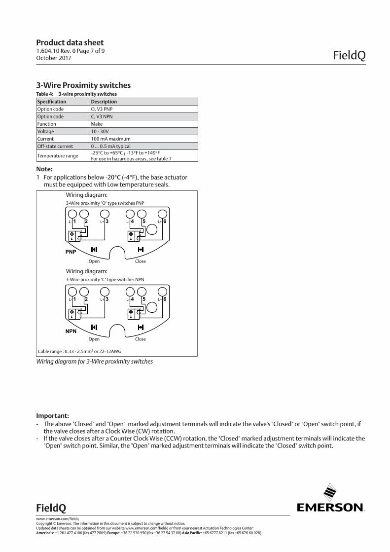
3-Wire Proximity switchesTable 4: 3-wire proximity switches
Specification Description
Option code O, V3 PNP
Option code C, V3 NPN
Function Make
Voltage 10 - 30V
Current 100 mA maximum
Off-state current 0 ... 0.5 mA typical
Temperature range-25°C to +65°C / -13°F to +149°FFor use in hazardous areas, see table 7
Note:1 For applications below -20°C (-4°F), the base actuator
must be equipped with Low temperature seals.
321 654
341
341
NPN
41
341
3
PNP
321 654L- L+ L- L+
L- L+ L- L+
Wiring diagram: 3-Wire proximity "O" type switches PNP
Open Close
Wiring diagram:3-Wire proximity "C" type switches NPN
Open Close
Cable range : 0.33 - 2.5mm2 or 22-12AWG
Wiring diagram for 3-Wire proximity switches
Important:- The above "Closed" and "Open" marked adjustment terminals will indicate the valve's "Closed" or "Open" switch point, if
the valve closes after a Clock Wise (CW) rotation.- If the valve closes after a Counter Clock Wise (CCW) rotation, the "Closed" marked adjustment terminals will indicate the
"Open" switch point. Similar, the "Open" marked adjustment terminals will indicate the "Closed" switch point.
1.604.10 Rev. 0 Page 7 of 9October 2017

Product data sheet
FieldQ
www.emerson.com/fieldqCopyright © Emerson. The information in this document is subject to change without notice. Updated data sheets can be obtained from our website www.emerson.com/fieldq or from your nearest Actuation Technologies Center: America’s: +1 281 477 4100 (fax 477 2809) Europe: +36 22 530 950 (fax +36 22 54 37 00) Asia Pacific: +65 6777 8211 (fax +65 626 80 028)
FieldQ
Control Module OptionsQC41, QC42 and QC43
45°
1 2
Local Manual Control
DescriptionFor commissioning, emergency or maintenance purposes, the FieldQ can be supplied with one or two Manual Control options. These can operate the pilot valve(s) inside the module and as such operate the actuator, when there is air pressure available, but no control signal or power supply.
Notes:- One Local Manual Control is required for normal
operation of Double acting or Spring return actuators. - For Double acting actuator with a Fail-in-last position
function, a second Local Manual Control can be mounted.
- These options can be ordered together with the Control Module or as a kit to be mounted later.
- For option ordering codes, see page 7
Speed Control
DescriptionThe FieldQ can be supplied with a Speed Control option. One throttle is required for Spring Return actuators and up to two for Double Acting actuators.The speed control throttle controls the air flow in and out of an air chamber and as such limits the speed of the “Opening” and “Closing” stroke simultaneously. This throttle consists of :1 Nut cover2 Main throttle with set screw.
Notes:- For Spring Return actuators with one speed control
throttle, it is not possible to set both the stroke cycle times to an equal time.
- Four Double Acting actuators it is possible to mount two speed control throttles.
- The actual stroke cycle times depend on the actual load on the actuator during the different strokes.
1.604.10 Rev. 0 Page 8 of 9October 2017
Local Manual Control option Speed control options
Location for 2nd
Local Manual Control
Spring Return:
Top entry only.
Lock
UnlockOn
Off
Default location of
Local Manual Control
Double Acting:
Bottom and/or top entries.

Product data sheet
FieldQ
www.emerson.com/fieldqCopyright © Emerson. The information in this document is subject to change without notice. Updated data sheets can be obtained from our website www.emerson.com/fieldq or from your nearest Actuation Technologies Center: America’s: +1 281 477 4100 (fax 477 2809) Europe: +36 22 530 950 (fax +36 22 54 37 00) Asia Pacific: +65 6777 8211 (fax +65 626 80 028)
FieldQ
Hazardous area specificationsModules QC41, QC42 and QC43
1.604.10 Rev. 0 Page 9 of 9October 2017
Notes:1 Each control module is marked with the applicable ambient temperature marking.2 Metric control modules are marked with ATEX and IECEx markings.3 Imperial control modules are marked with ATEX, IECEx, FM and CSA markings.
Temperature ratingTable 7: Temperature rating for use in areas with a potential explosion hazard.
Configuration Temperature (°C)
Module type Switch cartridgePneumatic
action
Max. Power
dissipation
Min.
ambient
Max.
ambient
Max.
SurfaceClass
QC41 (24VDC)M, G
O, C, N, H
S,D,F 3.6W (1 -25°C (-13°F) +60 +80 T6/T4
QC42, QC43 (115 or 230VAC) S,D 3.6W (1 -25°C (-13°F) +60 +80 T6/T4
QC42, QC43 (115 or 230VAC) F 7.2W (2 -25°C (-13°F) +60 +80 T6/T4
Switch cartridgeM = Mechanical switches G = Mechanical switches (gold contacts)C = 3 wire PNP proximity switchO = 3 wire NPN proximity switchN = 2 wire proximity switchH = 2 wire proximity switch
Pneumatic actionS = Spring Return (Single acting).D = Double acting.F = Double acting (Fail in Last Position)
Notes:1 1x or 2x 24VDC pilot valves, or 1x 115/230 VAC pilot valve 2 2x 115 or 230 VAC pilot valves
Below specification are applicable for QC41, QC42 and QC43 modules with a hazardous area approval.
APPROVED
Hazardous area product marking;
IECEx hazardous or Classified Location:
Ex d IIB+H2 T4/T6 Gb Ex t IIIC T80°C Db IECEx DEK 15.0034X
ATEX hazardous or Classified Location: 1180 II 2G Ex db IIB+H2 T4/T6 II 2D Ex tb IIIC T80°C DEKRA 15ATEX0055X
FM hazardous or Classified Location: CL I, II, III, DIV 1 Groups BCDEFG, T4/T6, Type 4X/6 CL l, ZN 1, IIB+H2, T4/T6
CSA hazardous or Classified Location: Class I, II, III, DIV 1 Groups CDEFG, T4/T6, Type 4X/6 Ex d IIB+H2 T4/T6 DIP A21 TA 80°C