ar82.60- p- 7502ea remove/ install radio 5.5.94 …avtolab.ru/_ld/0/6_v60supportinstr.pdfar82.60- p-...
TRANSCRIPT
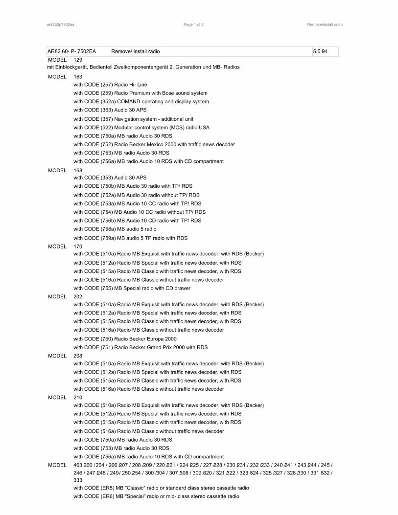
AR82.60- P- 7502EA Remove/ install radio 5.5.94MODEL 129mit Einblockgerät, Bedienteil Zweikomponentengerät 2. Generation und MB- Radios
MODEL 163with CODE (257) Radio Hi- Linewith CODE (259) Radio Premium with Bose sound systemwith CODE (352a) COMAND operating and display systemwith CODE (353) Audio 30 APS
with CODE (357) Navigation system - additional unitwith CODE (522) Modular control system (MCS) radio USAwith CODE (750a) MB radio Audio 30 RDSwith CODE (752) Radio Becker Mexico 2000 with traffic news decoderwith CODE (753) MB radio Audio 30 RDSwith CODE (756a) MB radio Audio 10 RDS with CD compartment
MODEL 168with CODE (353) Audio 30 APSwith CODE (750b) MB Audio 30 radio with TP/ RDS
with CODE (752a) MB Audio 30 radio without TP/ RDSwith CODE (753a) MB Audio 10 CC radio with TP/ RDSwith CODE (754) MB Audio 10 CC radio without TP/ RDSwith CODE (756b) MB Audio 10 CD radio with TP/ RDSwith CODE (758a) MB audio 5 radio
with CODE (759a) MB audio 5 TP radio with RDSMODEL 170
with CODE (510a) Radio MB Exquisit with traffic news decoder, with RDS (Becker)
with CODE (512a) Radio MB Special with traffic news decoder, with RDSwith CODE (515a) Radio MB Classic with traffic news decoder, with RDSwith CODE (516a) Radio MB Classic without traffic news decoderwith CODE (755) MB Special radio with CD drawer
MODEL 202with CODE (510a) Radio MB Exquisit with traffic news decoder, with RDS (Becker)with CODE (512a) Radio MB Special with traffic news decoder, with RDSwith CODE (515a) Radio MB Classic with traffic news decoder, with RDSwith CODE (516a) Radio MB Classic without traffic news decoder
with CODE (750) Radio Becker Europa 2000with CODE (751) Radio Becker Grand Prix 2000 with RDS
MODEL 208with CODE (510a) Radio MB Exquisit with traffic news decoder, with RDS (Becker)with CODE (512a) Radio MB Special with traffic news decoder, with RDSwith CODE (515a) Radio MB Classic with traffic news decoder, with RDSwith CODE (516a) Radio MB Classic without traffic news decoder
MODEL 210with CODE (510a) Radio MB Exquisit with traffic news decoder, with RDS (Becker)with CODE (512a) Radio MB Special with traffic news decoder, with RDSwith CODE (515a) Radio MB Classic with traffic news decoder, with RDS
with CODE (516a) Radio MB Classic without traffic news decoderwith CODE (750a) MB radio Audio 30 RDSwith CODE (753) MB radio Audio 30 RDSwith CODE (756a) MB radio Audio 10 RDS with CD compartment
MODEL 463.200 /204 / 206 /207 / 208 /209 / 220 /221 / 224 /225 / 227 /228 / 230 /231 / 232 /233 / 240 /241 / 243 /244 / 245 /246 / 247 /248 / 249/ 250 /254 / 300 /304 / 307 /308 / 309 /320 / 321 /322 / 323 /324 / 325 /327 / 328 /330 / 331 /332 /333with CODE (ER5) MB "Classic" radio or standard class stereo cassette radiowith CODE (ER6) MB "Special" radio or mid- class stereo cassette radio
ar8260p7502ea Remove/install radioPage 1 of 2

with CODE (ER7) MB "Exquisit" radio or comfort class stereo cassette radio
MODEL 414.700with CODE (EF8) Sound 10 radiowith CODE (EF9) Sound 20 radio
with CODE (EG5) Sound 30 radiowith CODE (EG6) Audio 10 comfort radio, D2B networked
The figure shows removal of radio in model 202
51 Removal toolsA2 Radio
P82.60- 0001- 06
�� Remove, Install
AR54.10-P-0003A1 Disconnect ground cable of battery � On model 163, 210, insulate cable terminalfor ground lead to prevent unintentional contactbetween disconnected ground lead and groundpoint W10
AR54.10-P-0003GModel 463 except 463.241 with code 979.
AR54.10-P-0003PVModel 463.241 with code 979.
2 Pull out radio (A2) � First, insert the detent release tools (51).Press retaining springs (arrow) back on removedradio (A2) and pull out removal plates (51)
BT82.60-P-9309-01Ak MB radio Model 202.
BT82.60-P-9309-01Bk MB radio As of 02/ 97.
BT82.60-P-9309-01Ck MB radio Model 129 as of 02/ 91.
3 Unplug electrical connectors.
4 Install in the reverse order
AR82.60-P-7502-01A5 Code radio Code 750, 751.AR82.60-P-7502-01BCode 510a, 512a, 515a, 516a, 755, ER5, ER6,
ER7.AR82.60-P-7502-01CModel 129.AR82.60-P-7502-01GCModels 168, 414.AR82.60-P-7502-01GHModel 163.
ar8260p7502ea Remove/install radioPage 2 of 2

AR68.10- P- 1400GI Remove/ install glove compartment 22.4.99MODEL 163.136 /154 / 172 #Aas of 145273,163.136 / 154 /172 #X as of 708319,
163.113 / 128 /157 / 174 /175
1 Glove compartment lid2 Screws3 Glove compartment4 Instrument panel5 Spreading rivetsE13/1 Glove compartment lamp
P68.10- 2330- 06
� � Remove/ Install
1 Open glove compartment lid (1)2 Unclip glove compartment lamp (E13/ 1) and
disconnect connector
*0005890110003 Unscrew bolt (2) � Torx bit set
4 Remove upper spreading rivets (5) from glove � Press pressure pin approx. 4 mm upwardcompartment (3) and remove spreading rivet downward.
5 Pull glove compartment (3) out of instrumentpanel (4)
6 Install in the reverse order � Align upper edge of glove compartment lid(1) in relation to instrument panel (4).
000 589 01 10 00
Torx bit set
ar6810p1400gi Remove/install glove compartmentPage 1 of 1

AR68.10- P- 1520GI Remove/ install cover below instrument panel (right) 2.6.99MODEL 163.136 /154 / 172 #Aas of 145273,163.136 / 154 /172 #X as of 708319,
163.113 / 128 /157 / 174 /175
1 Torx bolts2 Cover3 Locking leverX58/1 I nterior socket
P68.10- 2249- 06
� � Remove/ Install
1 Unscrew Torx screws (1) form cover (2)2 Fold locking lever (3) downward
3 Pull cover (2) downward and lay down4 Disconnect electrical connector from interior
socket (X58/ 1)5 Install in the reverse order
ar6810p1520gi Remove/install cover below instrument panel (right)Page 1 of 1

AR91.10- P- 1000GH Remove/ install front seat 3.3.97MODEL 163.113 /128 / 136 /154 / 157 /172 / 174 /175 with CODE (221b) Electrically adjustable driver and passengerseat
1 Torx socket screws2 Cover cap3 Front seat4 Torx socket bolt5 Belt end fitting6 ConnectorX55/3 Left front seat contacting stripX55/4 Right front seat connector block
P91.10- 0547- 06
� � Remove/ install
1 Remove headrest � See owner's manual2 Remove cover cap (2) from seat rail paneling � Set the seat height adjustment such that
the screw on the belt end fitting is visible.
*BA91.40-P-1001-01D3 Unscrew internal Torx drive bolt (4) from the �belt end fitting (5)
*000589011000� Torx bit set4 Remove belt end fitting (5)5 Unscrew internal Torx drive bolts (1) from the � Installation: Replace bolts.
front seat console
*BA91.10-P-1001-01B�*000589011000� Torx bit set
6 Move the front seat (3) forward7 Unscrew internal Torx drive bolts (1) from the � Installation: Replace bolts.
back seat console*BA91.10-P-1001-01B�*000589011000� Torx bit set
8 Detach connector (6) from the front left seatconnector block (X55/ 3) and the front right seatconnector block (X55/ 4)
9 Remove front seat (3)10 Install in the reverse order
� Front seats
Number Designation ModelSeries 163
BA91.10- P- 1001- 01B Bolt of seating mounting bracket to vehicle Nm 40floor
� Safety belts/ emergency tensioning retractors
Number Designation Model 163 up to Model 163 as of08/ 99 09/ 99
BA91.40- P- 1001- 01D Belt end fitting screw Nm 35 35
ar9110p1000gh Remove/install front seatPage 1 of 2

000 589 01 10 00
Torx bit set
ar9110p1000gh Remove/install front seatPage 2 of 2

AR68.20- P- 2310GH Removing and installing cover at gearshift lever 4.2.97MODEL 163.113 /136 / 154 /172 / 174 up to 31.8.01
1 Plastic frame2 Covering in front stowage compartment3 Center console insert4 Cover5 ConnectorsS21 Center console switch group
P68.20- 0434- 06
Operation no. of operation texts or standard texts and flat rates
Range Op. no. Operation textP 683450 REMOVING AND INSTALLING COVER FOR SHIFT LEVER
P 683455 REPLACING COVER FOR GEARSHIFT LEVER
� � Remove/ install
*1155890359001 Remove plastic frame (1) upward �2 Remove covering in stowage � Fastened with pin.
compartment (2)
3 Remove center console insert (3) � Remove screws (2 each) from insert floor
*1155890359004 Press cover (4) out of catch in center console at �rear and sides with long wedge
5 Disconnect connectors (5) from center consoleswitch group (S21)
6 Install in the reverse order
115 589 03 59 00
Long wedge
ar6820p2310gh Removing and installing cover at gearshift leverPage 1 of 1

DCAG Ref. No.This bulletin has been created and maintained in accordance with MBUSA-SLP 5.1, Document and Data Control, andMBUSA-SLP 16.1, Control of Quality Records.
© 2002 Mercedes-Benz USA, LLC All rights reserved. Reproduction or translation in wholeMercedes-Benz Canada, Inc. or in part is not permitted without authorization from theTechnical Information publisher. Printed in the USA.www.MBUSA.com 1-800-FOR-MERCedes
�
��
� �
��
�
ServiceDate: February 2002Order No.: S-B-82.70/179ASupersedes: S-B-82.70/179Group: 82
UPDATE:
SUBJECT:
Programming corrections—boldfaced print, pages 2 and 3 (This bulletin supersedesS-B-82.70/179 dated December 2001)
MODELS 129, 163, 170, 203, 208, 210, 215, 220, 230, 463
MODEL YEAR 2002/2003
V60 PORTABLE TELEPHONE PROGRAMMING
The following programming instructions are for the V60 portable telephone.
Questions concerning telephone selection in accordance with customer cellular carrier choice and/ortelephone programming should be addressed with the Mercedes-Benz/Motorola V60 Technical Hotline tollfree at 1-877-668-8600.
The programming sequence differs between a TDMA telephone and a CDMA telephone.

S-B-82.70/179A February 20022
TDMA PROGRAMMING
1. Obtain the following information from the cellular carrier before beginning the programming sequence:
• Cellular telephone number: __ __ __ - __ __ __ - __ __ __ __
• Carrier system I.D.: __ __ __ __ __ (I.D. number will be 1 to 5 digits)
2. Obtain the telephone security code from the customer. In a new telephone, it is set to 000000.
• Telephone security code: __ __ __ __ __ __ (Default is all zeros)
3. Program as follows:
Step To Press (Input) Phone Displays
1 Enter ProgrammingMode
Press: #, Carrier System I.D., #, *,“SEND”
Enter Security Code_ _ _ _ _ _
2 Enter Security CodePress: 0, 0, 0, 0, 0, 0 and select“OK” (This is the factory defaultcode)
ESN (Hex)
3 Enter Phone Number
Scroll down to MIN: --- --- --- ----and insert the ten digit MINthrough the keypad and select“OK” (MIN is the customer’scellular number)
IMSI
4 FinalizingProgramming
Select “DONE” (The handsetdisplay will turn off temporarily) Main Menu
Note: The telephone will display “Try Again” if an entry error is made. Press “CLR” to erase themessage/incorrect digits or press and hold “CLR” to clear all digits and then enter the correct numberand press “SEND.”
4. The telephone will power off after the “NAM Program Begins” message displays. When the telephone ispowered up again, it will search for the network and be ready for use.

S-B-82.70/179A�February 2002 3
CDMA PROGRAMMING1. Obtain the following information from the cellular carrier before beginning the programming sequence:
• Cellular telephone number: __ __ __ - __ __ __ - __ __ __ __
• Carrier analog system I.D.: __ __ __ __ __ (I.D. number will be 1 to 5 digits)
• Carrier digital system I.D.: __ __ __ __ __ (I.D. number will be 1 to 5 digits)
Note: Generally, the analog and digital system I.D. numbers will be the same. Questions regardingsystem I.D. numbers should be addressed with the cellular carrier.
2. Program as follows:
Step To Press (Input) Telephone Displays
1EnterProgrammingMode
Press: 7, 4, 6, 6, 3, #, MENU,MENU
Nam 1Nam 2
2 Selecting NAM Choose “SELECT” for NAM 1 MIN: 0000000000
3 Enter PhoneNumber
Insert the ten digit MINthrough the keypad and select“OK” (This is the customer’scellular number)
IMSI
4 Enter AMPSSystem I.D.
Scroll down to AMPS Sys ID,insert the number and select“OK” (AMPS data is providedby the carrier)
CDMA Sys ID:
5 Enter CDMASystem I.D.
Insert the CDMA Sys ID andselect “OK” (CDMA data isprovided by the carrier)
MIN:
6 FinalizingProgramming
Select “DONE” and then pressthe “END” key
Main Menu
Note: The telephone will display “Try Again” if an entry error is made. Press “CLR” to erase themessage/incorrect digits or press and hold “CLR” to clear all digits and then enter the correct numberand press “STO.”
3. After the “Entry Done” message appears, the telephone will display “Searching” as it attempts to contacta network. When the “Searching” message disappears, the telephone is ready for use.
4. To program a second number, follow step 1 in the table below and steps 2-6 in the above table.
Step To Press (Input) Phone Displays
1Enter NAM2ProgrammingMode
7, 4, 6, 6, 3, #, 2, FCN, FCN Enter MIN
Note: Be sure to obtain the system I.D. for each before beginning the programming sequence if thesecond through fourth numbers are with different cellular carriers.
Note: The CDMA telephone has a two telephone number maximum. Refer to the operation guide forinstructions on how to switch between the various telephone numbers.

DCAG Ref. No.This bulletin has been created and maintained in accordance with MBUSA-SLP 5.1, Document and Data Control, andMBUSA-SLP 16.1, Control of Quality Records.
© 2000 Mercedes-Benz USA, LLC All rights reserved. Reproduction or translation in wholeMercedes-Benz Canada, Inc. or in part is not permitted without authorization from theTechnical Information publisher. Printed in the USA.www.MBUSA.com 1-800-FOR-MERCedes
������������Date: August 2000Order No.: S-SI-82.64/135Supersedes:
Group: 82
SUBJECT: MODELS 129, 163, 170, 203, 208, 210, 215, 220
MODEL YEAR 2001
D2B FIBER OPTIC CONFIGURATION AND VERSION CODING
Following are fiber optics installation general handling notes and generic configuration diagrams for the abovereferenced vehicles. Model specific references are included where applicable.
A. D2B general notes1. Fibers are easily damaged and must be handled with
care to prevent cuts, nicks, abrasions, kinks and/orcrushing.
2. Fiber minimum bend radius is 25 mm. A bend radiusless than 25 mm will permanently damage the fiber,thus necessitating replacement.
3. Optical fibers have a ring type configuration (i.e. Theoutput of the previous component is coupled to theinput of the next component in a daisy chain type loop.The ring must form a closed loop in order to function[Figure 1]).
4. Light enters the clear fiber (input) and exits the redfiber (output). Each active D2B connector musttherefore contain one red and one clear fiber (Figure1).
5. The red fiber is always on the chamfered side and theclear fiber on the square side of the connector (Figure1).
Figure 1
MASTER
SLAVE 1
SLAVE 2SLAVE 3
SLAVE n
= Red Fiber
= Clear Fiber
S-SI-82.64/135 ��� August 20002
6. All fiber connections or couplings should follow a clear to red logic. A coupling must never contain twofibers of the same color (Figure 1).
Note: Due to the keying of the fibers, this would only be possible through forced insertion.
7. Fiber optic (D2B) cables are identified by orange/brown semi-rigid insulation.8. The fibers are loosely pre-wired with the vehicle electrical harnesses in most applications. The fibers are
not affected by electromagnetic interference (EMI) from the bundled vehicle electrical harnesses.
B. Configuring the D2B ring1. Vehicles delivered from the factory may have active fibers (e.g. optical amplifier and/or factory installed
CD), inactive fibers (e.g. no amplifier or accessories installed), or no fibers. Vehicles will vary inaccordance with the equipment installed. Some vehicles will have all required fibers installed while otherswill contain additional fiber links in the accessory kit(s). Refer to the respective accessory reference forfiber location information.
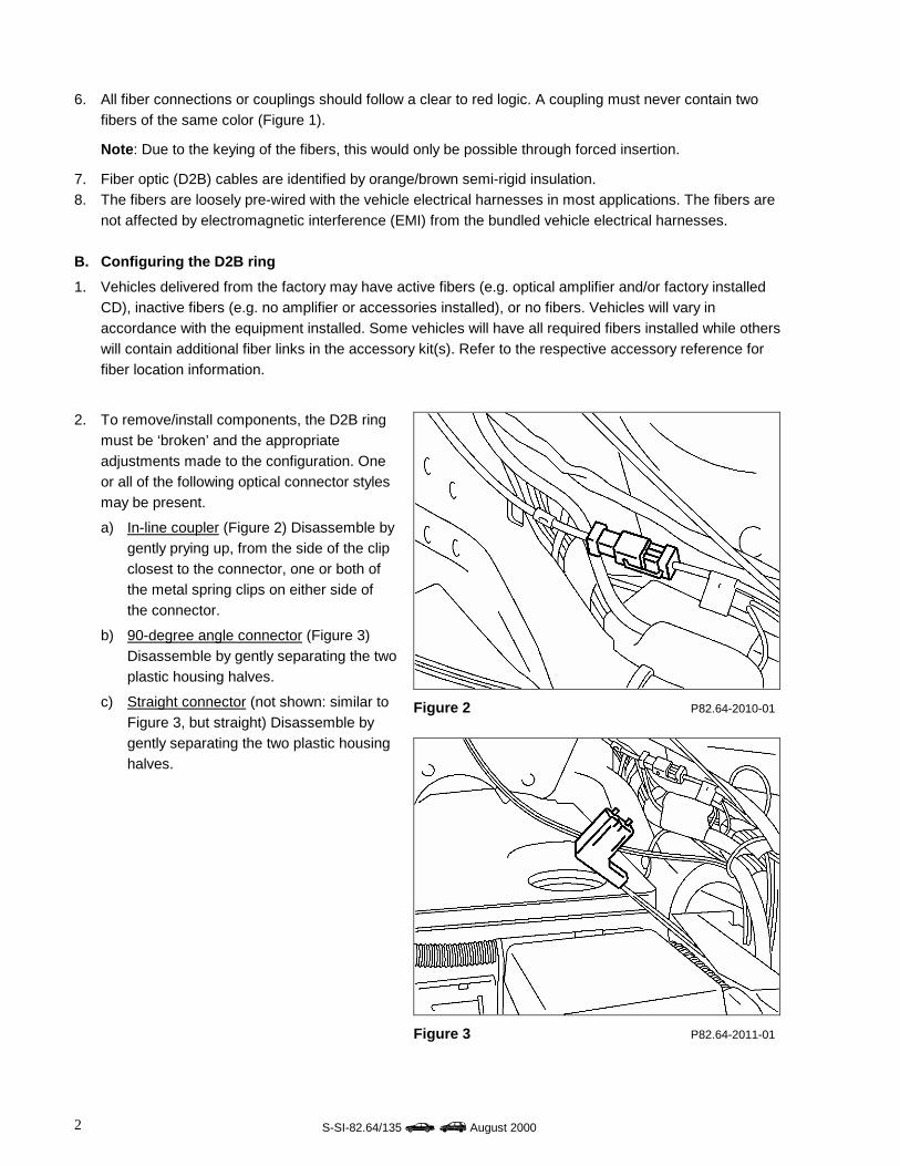
2. To remove/install components, the D2B ringmust be ‘broken’ and the appropriateadjustments made to the configuration. Oneor all of the following optical connector stylesmay be present.
a) In-line coupler (Figure 2) Disassemble bygently prying up, from the side of the clipclosest to the connector, one or both ofthe metal spring clips on either side ofthe connector.
b) 90-degree angle connector (Figure 3)Disassemble by gently separating the twoplastic housing halves.
c) Straight connector (not shown: similar toFigure 3, but straight) Disassemble bygently separating the two plastic housinghalves.
Figure 2 P82.64-2010-01
Figure 3 P82.64-2011-01
S-SI-82.64/135 ���� August 2000 3
3. Exercise extreme care when disassembling connectors and handling fibers to ensure that no fiber endsare damaged. Fiber end damage will result in light loss that may lead to intermittent D2B ring operationand/or failure.
4. The D2B ring configuration varies according to vehicle type and in accordance with the vehicle’sequipment level and necessity to add or remove. Refer to Section C and use the following examples asguides in determining how to configure the D2B ring.
C. D2B ring version coding
1. The D2B master (radio or head unit) must recognize the ring configuration in order for the D2B ring toproperly function. The ring configuration is critical to the proper function of the D2B self-diagnosticsystems. Improperly version coded rings may intermittently malfunction and will generate false diagnostictrouble codes (DTC’s).
2. Version coding is performed using StarDiagnosis (SDS). While the exact path to the version codingscreens may differ according to the equipment used and software updates made, the following samplepath represents how to access this function on the diagnostic equipment:• Control units / Information and communication / D2B / Control unit adaptations / D2B nominal
configuration3. Once in the configuration screen, the individual D2B components must be set to the appropriate
configuration. The diagrams following illustrate proper version coding assignments for each model.4. The diagrams following, are examples of D2B ring configurations with the maximum number of ring
components. Some installations will not include all of the components shown in the examples. If acomponent is not present, connect the preceding component output to the input of the one following thecomponent not present.
5. Do not leave any blank or Not Present between components when setting the configuration. Allcomponents must be listed one after the other in proper order, and then after the last component, theremaining entries should be set to Not Present.
6. Only vehicles with COMAND or MCS include the Tele Aid 2 module in the D2B ring.

S-SI-82.64/135 ��� August 20004
Model 129 (SL-Class) D2B Ring Configuration
P82.64-2239-11
Model 163 (M-Class) D2B Ring Configuration
P82.64-2240-11

S-SI-82.64/135 ���� August 2000 5
Model 170 (SLK-Class) D2B Ring Configuration
P82.64-2241-11
Model 203 (C-Class) D2B Ring Configuration
P82.64-2242-11

S-SI-82.64/135 ��� August 20006
Model 208 (CLK-Class) D2B Ring Configuration
P82.64-2243-11
Model 210 (E-Class) D2B Ring Configuration

S-SI-82.64/135 ���� August 2000 7
P82.64-2244-11
Model 215 (CL-Class) D2B Ring Configuration
P82.64-2245-11

S-SI-82.64/135 ��� August 20008
Model 220 (S-Class) D2B Ring Configuration
P82.64-2246-11
7. Confirm that the programmed and actual configurations are the same once the ring has been properlyversion coded. This can be accomplished by using the D2B actual values function. Again, the paths toaccess this feature may vary depending on the test equipment and software level, but the following is arepresentative sample:• Actual values/D2B actual configuration
8. Verify that the version coding input (specified value) matches the actual configuration performed duringinstallation (actual values). If a difference exists, the ring has been improperly configured and must bedisassembled to diagnose and correct the error.
� CAUTIONDO NOT alter the configurations in the diagrams to match the vehicle configuration. Failure tohave the configuration set as illustrated in the preceding diagrams will result in erroneous systemoperation and/or intermittent failure of some or all components as well as failure of the diagnosticsystem to provide accurate diagnostic messages.
9. Check the DTC memory of all installed components and the head unit. Any present DTC(s) should bediagnosed, identified, corrected and the DTC memory cleared.
Note: Powering up a newly installed system prior to version coding will set D2B ring configuration errors.These errors may be ignored during the initial DTC check. If, after clearing the DTC(s), they return insubsequent operation of the system, a configuration error is present that must be located and corrected.
10. Perform a short functional test on the D2B system group and confirm that no new DTC’s have been set.