architectural design specification
TRANSCRIPT

Architectural Design Specification Electric-Eye
Nichelous Herndon
Adis Kovacevic
Zack Davis
Juan Sifuentes
Rommel Alonzo
Architectural Design Specification | 2
Document Last Updated on 1/31/2013
TABLE OF CONTENTS
List of Figures 5
List of Tables 6
Document Revision History 7
1. Introduction 8
1.1 Overview 8
1.2 Product Concept 8
1.3 Project Scope 9
2. Meta-Architecture 10
2.1 Architectural Vision 10
2.2 Guiding Assumptions 10
2.3 Guiding Principles 10
2.4 Tradeoffs 11
3. Architecture Overview 12
3.1 Block Diagram 12
3.2 Input/output (I/O) Interface Layer 12
3.3 Data Processing Layer 13
3.4 Communication Layer 13
4. I/O Interface Layer 15
4.1 Description 15
4.2 Purpose 15
4.3 Function 15
4.4 Dependencies 16

Architectural Design Specification | 3
Document Last Updated on 1/31/2013
4.5 Interfaces 16
4.6 Subsystems 16
5. Data Processing Layer 19
5.1 Description 19
5.2 Purpose 19
5.3 Function 19
5.4 Dependencies 19
5.5 Interfaces 20
5.6 Subsystems 20
6. Communication Layer 25
6.1 Description 25
6.2 Purpose 25
6.3 Function 25
6.4 Dependencies 25
6.5 Interfaces 26
6.6 Processing 26
6.7 Data 26
6.8 Subsystems 26
7. Operating System Dependencies 29
7.1 Overview 29
7.2 I/O Interface Layer 29
7.3 Data Processing Layer 29
7.4 Communication Layer 29
8. Inter-Subsystem Data Flow 30

Architectural Design Specification | 4
Document Last Updated on 1/31/2013
8.1 Overview 31
8.2 Inter-Subsystem Data Element Descriptions 31
8.3 Producer-Consumer Relationship 32
9. Requirements Mapping 34
9.1 Overview 34
10. Testing Considerations 35
10.1 Overview 35
10.2 Testing Approach 35
10.3 I/O Interface Layer 35
10.4 Data Processing Layer 36
10.5 Communication Layer 36
11. Glossary 38
11.1 Robot Operating System (ROS) 38
11.2 Point Cloud Library (PCL) 38
11.3 Transformation Matrix (6DOF) 38
11.4 RGB-D Camera 38
11.5 OpenNI 38
11.6 Point Cloud 39
11.7 Point Cloud Frame 39
11.8 Mapping 39
11.9 Localization 39
11.10 ROS Node 39

Architectural Design Specification | 5
Document Last Updated on 1/31/2013
List of Figures Figure 1-1: Product Concept .................................................................................................................. 8
Figure 3-1: Electric-Eye Block Diagram .................................................................................................12
Figure 4-1: I/O Interface Layer with Subsystems .................................................................................. 15
Figure 5-1: Data Processing Layer with Subsystems ............................................................................ 19
Figure 6-1: Communication Layer with Subsystems ............................................................................ 25
Figure 8-1: Inter-Subsystem Data Flow ............................................................................................... 30

Architectural Design Specification | 6
Document Last Updated on 1/31/2013
List of Tables Table 4-1: I/O Interface Layer Interfaces .............................................................................................. 16
Table 4-2: RGB-D Camera Interpreter Subsystem Interfaces ............................................................... 17
Table 4-3: Signal Interpreter Subsystem Interfaces .............................................................................. 17
Table 5-1: Data Processing Layer Interfaces ........................................................................................ 20
Table 5-2: Controller Subsystem Interfaces ..........................................................................................21
Table 5-3: Localization Subsystem Interfaces ...................................................................................... 22
Table 5-4: Mapping Subsystem Interfaces ............................................................................................23
Table 5-5: Store Frame Subsystem Interfaces ......................................................................................23
Table 5-6: Camera Handler Subsystem Interfaces ............................................................................... 24
Table 6-1: Communication Layer Interfaces ........................................................................................ 26
Table 6-2: Pack Transformation Matrix Subsystem Interfaces ............................................................. 27
Table 6-3: Command Interpreter Subsystem Interfaces ....................................................................... 27
Table 8-1: Inter-Subsystem Data Element Descriptions .......................................................................32
Table 8-2: Producer-Consumer Relationship ........................................................................................ 33
Table 9-1: Requirements Mapping ....................................................................................................... 34
Architectural Design Specification | 7
Document Last Updated on 1/31/2013
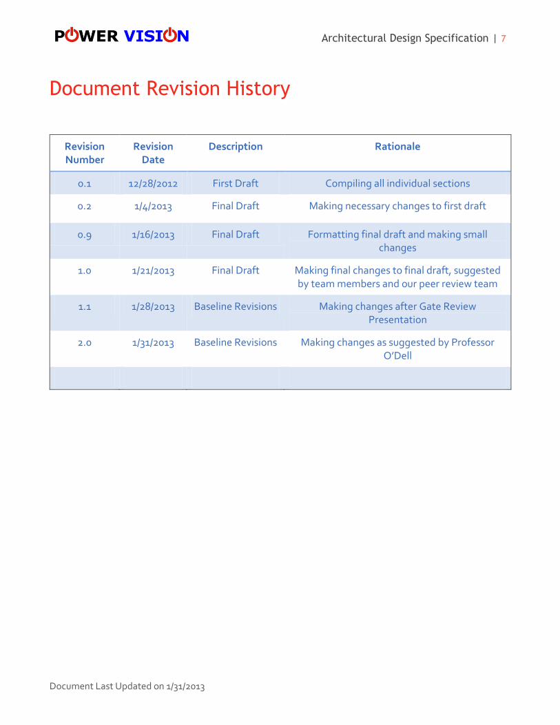
Document Revision History
Revision Number
Revision Date
Description Rationale
0.1 12/28/2012 First Draft Compiling all individual sections
0.2 1/4/2013 Final Draft Making necessary changes to first draft
0.9 1/16/2013 Final Draft Formatting final draft and making small changes
1.0 1/21/2013 Final Draft Making final changes to final draft, suggested by team members and our peer review team
1.1 1/28/2013 Baseline Revisions Making changes after Gate Review Presentation
2.0 1/31/2013 Baseline Revisions Making changes as suggested by Professor O’Dell
Architectural Design Specification | 8
Document Last Updated on 1/31/2013
1. Introduction
1.1 Overview
The Architectural Design Specification will cover the architectural design of the Electric-Eye and
include details of the product concept, scope, and key requirements.
1.2 Product Concept
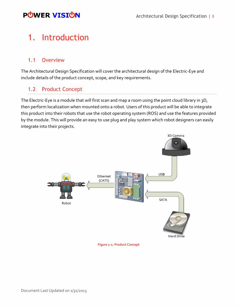
The Electric-Eye is a module that will first scan and map a room using the point cloud library in 3D,
then perform localization when mounted onto a robot. Users of this product will be able to integrate
this product into their robots that use the robot operating system (ROS) and use the features provided
by the module. This will provide an easy to use plug and play system which robot designers can easily
integrate into their projects.
Figure 1-1: Product Concept
Architectural Design Specification | 9
Document Last Updated on 1/31/2013
1.3 Project Scope
The Electric-Eye will be limited to a standard sized room. It should be an easy to use system where the
module shall assist the robot by giving it precise and formatted data. The key requirements will
represent the most important functionalities that the Electric-Eye needs to make it successful.
The Electric-Eye must be able to scan an average size indoor room, map a world model based on the
frames stored, and localize a robot based on its location in the world map. All of these operations
must be processed within a reasonable time, and it is only allowed to be in one mode at a given period.
The product must also be ROS compatible to the extent that it can send the transformation matrix
and receive simple standard commands from ROS. What the robot does with the information
provided by the product is up to the robot designer.
For packaging requirements, the Electric-Eye has to be physically mountable to a robot (which
depends on the user). It must also have a single case housing to provide minimal interference with the
robot. Since safety is a great concern, the Electric-Eye must have no sharp edges and be able to
prevent fires from overheating and power surges.
Other requirements that must be noted are that the Electric-Eye has to be tested to ensure
functionality and be able to operate under small vibration such as a robot operating on rugged terrain.
Since it will draw power from a robot, it must not draw more than 150 watts of power, and be able to
have an on board storage of at least 8 GB. To finalize the product, we will include documentation in
American English, and will not provide further maintenance after May 2013.
Architectural Design Specification | 10
Document Last Updated on 1/31/2013
2. Meta-Architecture
2.1 Architectural Vision
The Electric-Eye is a module that will use a RGB-D camera to read in frames from the surrounding
environment. The frames will then be processed and converted into a map that the system will use to
perform localization operations with. Once localization is completed, a transformation matrix will be
sent to ROS. Given the functionality of the Electric-Eye along with our guiding principles, we have
decided to split the architecture into 3 layers: I/O Interface, Data Processing, and Communication.
Each layer will be independent of the other layers which will make the system easier to change, should
change be needed in a certain layer.
2.2 Guiding Assumptions
When designing the architecture for the Electric-Eye, we came up with some assumptions that impact
the design of the product. The following are the guiding assumptions for the Electric-Eye:
Power will be provided by the host robot
The module will be used indoors.
The module will be used in a well-lit area
Mapping operations will be performed before localization operations
2.3 Guiding Principles
Guiding principles are rules that we have discussed as a team and decided on. These principles will
influence the design of the system which will help us ensure that the system is working properly and
will also ensure that we meet our customer’s requirements.
2.3.1 Modularity
Components of the system shall work independently and shall also work together as a whole.
2.3.2 Component Recovery
System components shall recover from software failures experienced within their own layer
subsystems. Software failure will be limited to one layer. In other words, an error will not extend
beyond the layer it originated from. The error will be contained, and the layer will do appropriate
exception handling.
Architectural Design Specification | 11
Document Last Updated on 1/31/2013
2.3.3 Extensibility
The system shall be designed so that the signal interpreter subsystem will have the ability to handle
more than 3 switch positions if a user decides to further extend the modes of the Electric-Eye.
2.3.4 External Compatibility
The system must be able to integrate with ROS and any RGB-D camera that is OpenNI compatible.
2.3.5 Software Efficiency
The system software components shall not overwhelm storage and/or memory resources.
2.4 Tradeoffs
The first tradeoff that we had when designing the systems architecture involved the on-board storage
component. Originally we wanted to have storage as its own separate layer that would handle the
storing of frames and would also retrieve data and send it to the data processing layer. In the end, we
decided to keep the system simple and make the storage component a part of the data processing
layer. The decision to make it only part of the data processing layer still keeps our system modular and
keeps our layers independent of each other because the data processing layer is the only layer that
accesses the on-board storage.
Another tradeoff involved which camera we would be using for the module. Initially the project was
going to use the Kinect camera to read in frames to the module. Since we are using the PCL library to
handle our mapping and localization algorithms we decided that we could use any camera that is
OpenNI compatible to read in frames to the module. Designing the system to use any OpenNI
compatible card will allow more flexibility to the users of the module allowing them to use cameras
other than the Kinect.
Architectural Design Specification | 12
Document Last Updated on 1/31/2013
3. Architecture Overview
3.1 Block Diagram
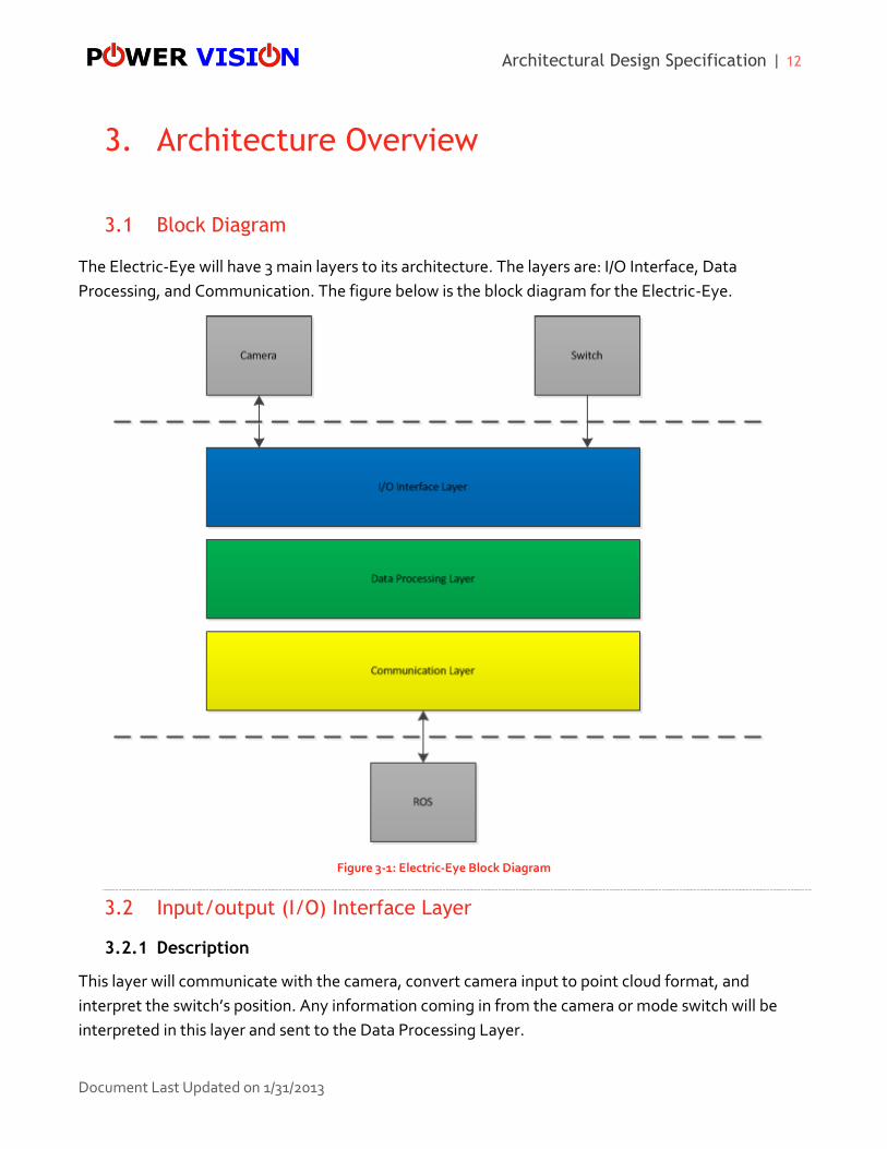
The Electric-Eye will have 3 main layers to its architecture. The layers are: I/O Interface, Data
Processing, and Communication. The figure below is the block diagram for the Electric-Eye.
Figure 3-1: Electric-Eye Block Diagram
3.2 Input/output (I/O) Interface Layer
3.2.1 Description
This layer will communicate with the camera, convert camera input to point cloud format, and
interpret the switch’s position. Any information coming in from the camera or mode switch will be
interpreted in this layer and sent to the Data Processing Layer.
Architectural Design Specification | 13
Document Last Updated on 1/31/2013
3.2.2 Services Provided
Sends point cloud data to the Data Processing Layer
Sends commands to the camera
Sends switch mode to Data Processing Layer
3.2.3 Services Expected
Raw data from the camera
Raw data from the switch
Camera command from the Data Processing Layer
3.3 Data Processing Layer
3.3.1 Description
This layer will perform read/write operations to the on-board storage component along with mapping
and localization operations. All major processing will be handled in this layer, specifically the world
map and transformation matrix.
3.3.2 Services Provided
Commands to the I/O Interface Layer for camera control
Transformation matrix to the Communication Layer
3.3.3 Services Expected
Switch mode from the I/O Interface Layer
Point cloud frame from the I/O Interface Layer
ROS sleep command from the Communication Layer
3.4 Communication Layer
3.4.1 Description
This layer will provide the necessary communication between the module and ROS. In this layer,
messages will be packed into ROS format and transmitted to ROS. This layer will also receive
commands from ROS, when a message is received it will be unpacked, interpreted, and sent to the
Data Processing Layer.
Architectural Design Specification | 14
Document Last Updated on 1/31/2013
3.4.2 Services Provided
Packs a transformation matrix and sends it to ROS
Unpacks and interprets ROS messages and sends them to the Data Processing Layer
3.4.3 Services Expected
A transformation matrix is expected from the Data Processing Layer
Commands from ROS
Architectural Design Specification | 15
Document Last Updated on 1/31/2013
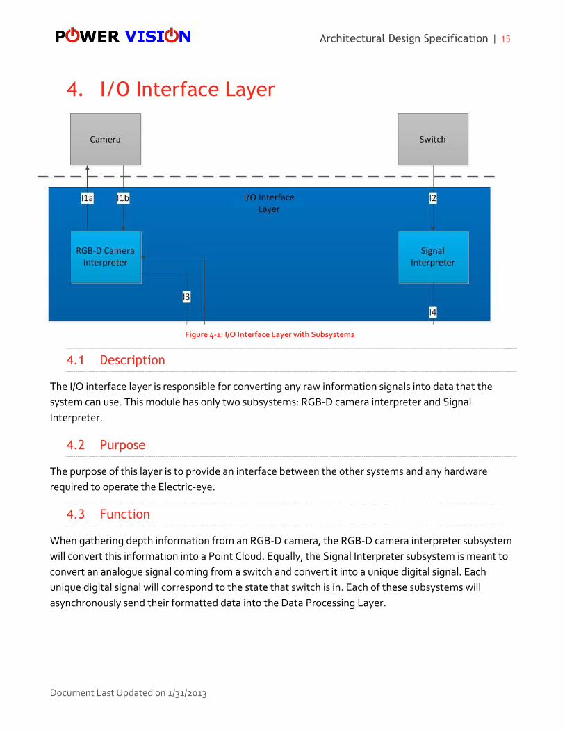
4. I/O Interface Layer
4.1 Description
The I/O interface layer is responsible for converting any raw information signals into data that the
system can use. This module has only two subsystems: RGB-D camera interpreter and Signal
Interpreter.
4.2 Purpose
The purpose of this layer is to provide an interface between the other systems and any hardware
required to operate the Electric-eye.
4.3 Function
When gathering depth information from an RGB-D camera, the RGB-D camera interpreter subsystem
will convert this information into a Point Cloud. Equally, the Signal Interpreter subsystem is meant to
convert an analogue signal coming from a switch and convert it into a unique digital signal. Each
unique digital signal will correspond to the state that switch is in. Each of these subsystems will
asynchronously send their formatted data into the Data Processing Layer.
Figure 4-1: I/O Interface Layer with Subsystems
Architectural Design Specification | 16
Document Last Updated on 1/31/2013
4.4 Dependencies
The I/O interface layer depends on receiving information from two sources. The first source is from an
OpenNI compatible RGB-D camera meant to provide this layer with depth information of its
surroundings. The second source is from a switch which is meant to represent the current state of the
Electric-Eye.
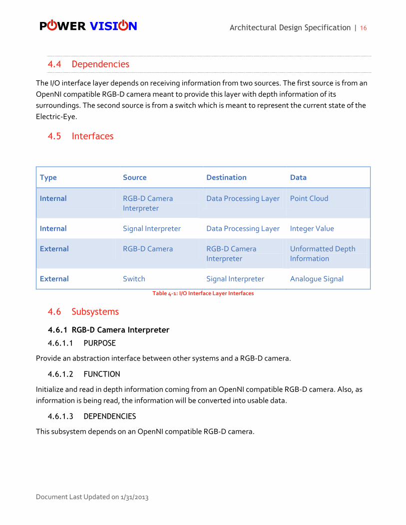
4.5 Interfaces
Type Source Destination Data
Internal RGB-D Camera Interpreter
Data Processing Layer Point Cloud
Internal Signal Interpreter Data Processing Layer Integer Value
External RGB-D Camera RGB-D Camera Interpreter
Unformatted Depth Information
External Switch Signal Interpreter Analogue Signal
Table 4-1: I/O Interface Layer Interfaces
4.6 Subsystems
4.6.1 RGB-D Camera Interpreter
4.6.1.1 PURPOSE
Provide an abstraction interface between other systems and a RGB-D camera.
4.6.1.2 FUNCTION
Initialize and read in depth information coming from an OpenNI compatible RGB-D camera. Also, as
information is being read, the information will be converted into usable data.
4.6.1.3 DEPENDENCIES
This subsystem depends on an OpenNI compatible RGB-D camera.

Architectural Design Specification | 17
Document Last Updated on 1/31/2013
4.6.1.4 INTERFACES
Type Source Destination Data
Internal RGB-D Camera Interpreter
Data Processing Layer Point Cloud
External RGB-D Camera RGB-D Camera Interpreter
Unformatted Depth Information
Table 4-2: RGB-D Camera Interpreter Subsystem Interfaces
4.6.1.5 PROCESSING
The subsystem will convert depth information into Point Cloud data object.
4.6.1.6 DATA
The data produced will be depth information of the module’s current surroundings.
4.6.2 Signal Interpreter
4.6.2.1 PURPOSE
Provide an abstraction interface between other systems and the switch.
4.6.2.2 FUNCTION
This subsystem is meant to take in an analogue signal that is controlled by switch and convert it into a
corresponding digital signal. This signal is then sent to the Data Processing Layer.
4.6.2.3 DEPENDENCIES
This subsystem is dependent on a hardware switch.
4.6.2.4 INTERFACES
Type Source Destination Data
Internal Signal Interpreter Data Processing Layer Integer Value
External Switch Signal Interpreter Analogue Switch
Table 4-3: Signal Interpreter Subsystem Interfaces

Architectural Design Specification | 18
Document Last Updated on 1/31/2013
4.6.2.5 PROCESSING
Convert analogue signal into an integer value.
4.6.2.6 DATA
Data will consist of an analogue switch signal.
Architectural Design Specification | 19
Document Last Updated on 1/31/2013
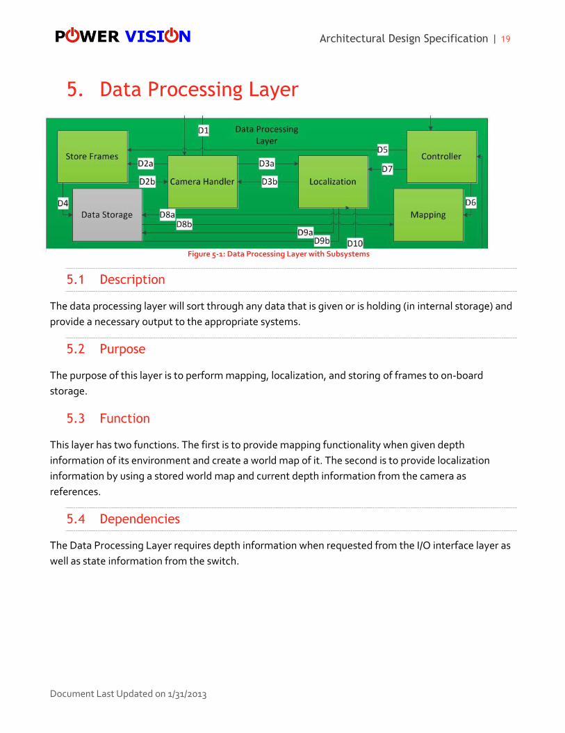
5. Data Processing Layer
5.1 Description
The data processing layer will sort through any data that is given or is holding (in internal storage) and
provide a necessary output to the appropriate systems.
5.2 Purpose
The purpose of this layer is to perform mapping, localization, and storing of frames to on-board
storage.
5.3 Function
This layer has two functions. The first is to provide mapping functionality when given depth
information of its environment and create a world map of it. The second is to provide localization
information by using a stored world map and current depth information from the camera as
references.
5.4 Dependencies
The Data Processing Layer requires depth information when requested from the I/O interface layer as
well as state information from the switch.
Figure 5-1: Data Processing Layer with Subsystems

Architectural Design Specification | 20
Document Last Updated on 1/31/2013
5.5 Interfaces
Type Source Destination Data
External I/O Interface Layer Camera Handler Point Cloud
External I/O Interface Layer Controller Integer Value
External Localization Communication Layer 6DOF Frame
External Command Interpreter Controller Command
Internal Controller Localization Status Signal
Internal Controller Mapping Status Signal
Internal Controller Store Frame Status Signal
Internal Camera Handler Localization Point Cloud
Internal Camera Handler Store Frame Point Cloud
External Store Frame Internal Storage Point Cloud
External Internal Storage Localization Point Cloud
Table 5-1: Data Processing Layer Interfaces
5.6 Subsystems
5.6.1 Controller
5.6.1.1 PURPOSE
The purpose of this subsystem is to help control which other subsystems are supposed to be
operating. By sending control signals, the controller subsystem can turn on/off any other subsystem as
required.

Architectural Design Specification | 21
Document Last Updated on 1/31/2013
5.6.1.2 FUNCTION
This subsystem will be able to send control signals to other subsystems to turn them on/off. Also from
the communication layer, it must be able to receive a control state signal to effectively place the RGB-
D camera in sleep mode.
5.6.1.3 DEPENDENCIES
This subsystem is dependent on receiving signals from both the I/O and Communication Layer to
determine what state the other subsystems need to be in.
5.6.1.4 INTERFACES
Type Source Destination Data
External I/O Interface Layer Controller Integer Value
External Command Interpreter Controller Command
Internal Controller Localization Status Signal
Internal Controller Mapping Status Signal
Internal Controller Store Frame Status Signal
Table 5-2: Controller Subsystem Interfaces
5.6.1.5 PROCESSING
The purpose of this subsystem is to send control information to respective subsystems.
5.6.1.6 DATA
Receives control and binary state number from other external systems and also send respective
control signals to other subsystems.
5.6.2 Localization
5.6.2.1 PURPOSE
The purpose of this subsystem is to compute localization information.
5.6.2.2 FUNCTION
By receiving current depth information from the Camera Handler subsystem, the subsystem will
compute localization information using a stored world map.
Architectural Design Specification | 22
Document Last Updated on 1/31/2013
5.6.2.3 DEPENDENCIES
This subsystem depends on receiving control information from the Controller subsystem and from
receiving current depth information from the Camera Handler. Also, the subsystem gains access to
the world map by reading it in from its internal storage drive.
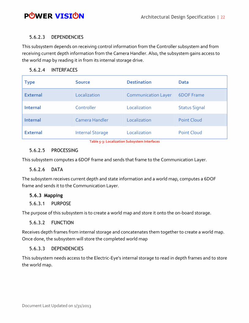
5.6.2.4 INTERFACES
Type Source Destination Data
External Localization Communication Layer 6DOF Frame
Internal Controller Localization Status Signal
Internal Camera Handler Localization Point Cloud
External Internal Storage Localization Point Cloud
Table 5-3: Localization Subsystem Interfaces
5.6.2.5 PROCESSING
This subsystem computes a 6DOF frame and sends that frame to the Communication Layer.
5.6.2.6 DATA
The subsystem receives current depth and state information and a world map, computes a 6DOF
frame and sends it to the Communication Layer.
5.6.3 Mapping
5.6.3.1 PURPOSE
The purpose of this subsystem is to create a world map and store it onto the on-board storage.
5.6.3.2 FUNCTION
Receives depth frames from internal storage and concatenates them together to create a world map.
Once done, the subsystem will store the completed world map
5.6.3.3 DEPENDENCIES
This subsystem needs access to the Electric-Eye's internal storage to read in depth frames and to store
the world map.
Architectural Design Specification | 23
Document Last Updated on 1/31/2013
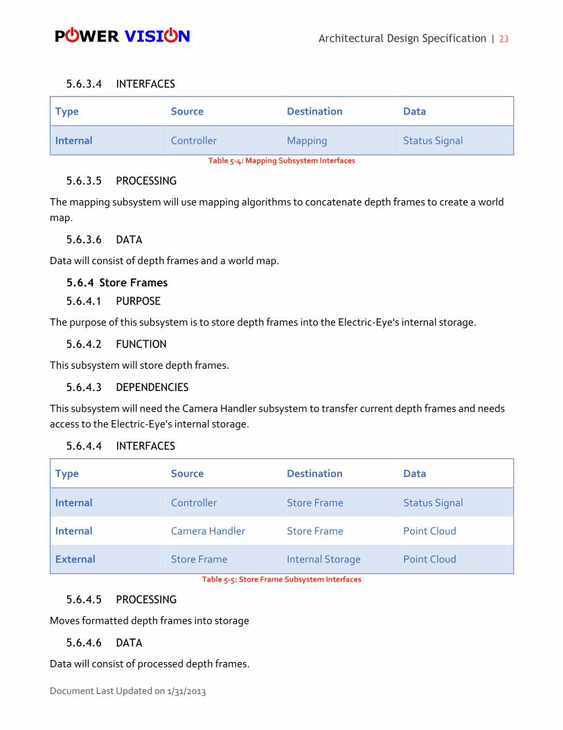
5.6.3.4 INTERFACES
Type Source Destination Data
Internal Controller Mapping Status Signal
Table 5-4: Mapping Subsystem Interfaces
5.6.3.5 PROCESSING
The mapping subsystem will use mapping algorithms to concatenate depth frames to create a world
map.
5.6.3.6 DATA
Data will consist of depth frames and a world map.
5.6.4 Store Frames
5.6.4.1 PURPOSE
The purpose of this subsystem is to store depth frames into the Electric-Eye's internal storage.
5.6.4.2 FUNCTION
This subsystem will store depth frames.
5.6.4.3 DEPENDENCIES
This subsystem will need the Camera Handler subsystem to transfer current depth frames and needs
access to the Electric-Eye's internal storage.
5.6.4.4 INTERFACES
Type Source Destination Data
Internal Controller Store Frame Status Signal
Internal Camera Handler Store Frame Point Cloud
External Store Frame Internal Storage Point Cloud
Table 5-5: Store Frame Subsystem Interfaces
5.6.4.5 PROCESSING
Moves formatted depth frames into storage
5.6.4.6 DATA
Data will consist of processed depth frames.

Architectural Design Specification | 24
Document Last Updated on 1/31/2013
5.6.5 Camera Handler
5.6.5.1 PURPOSE
The purpose of the Camera Controller subsystem is to be a waypoint for other subsystem in the Data
Processing Layer to control the RGB-D camera.
5.6.5.2 FUNCTION
Send control information and receive depth frames from I/O Interface Layer.
5.6.5.3 DEPENDENCIES
N/A
5.6.5.4 INTERFACES
Type Source Destination Data
External I/O Interface Layer Camera Handler Point Cloud
Internal Camera Handler Localization Point Cloud
Internal Camera Handler Store Frame Point Cloud
Table 5-6: Camera Handler Subsystem Interfaces
5.6.5.5 PROCESSING
N/A
5.6.5.6 DATA
Data will consist of processed depth frames.

Architectural Design Specification | 25
Document Last Updated on 1/31/2013
6. Communication Layer
6.1 Description
The Communication layer is responsible for handling all ROS communication for the Electric-Eye. It
will receive data that is outgoing and pack it into a ROS compatible message. It also receives ROS
messages, unpacks them, filters the message for appropriate commands, and sends them out to the
Data Processing Layer.
6.2 Purpose
The purpose of this layer is to centralize all ROS communications and allow for an interface with the
module and ROS.
6.3 Function
The Communication Layer will provide the Electric-Eye with the ROS commands that are coming in,
filtering out unimplemented commands. It will also send out the modules transformation matrix to
external ROS.
6.4 Dependencies
The Communication Layer is dependent on the Localization subsystem in the Data Processing Layer.
Figure 6-1: Communication Layer with Subsystems

Architectural Design Specification | 26
Document Last Updated on 1/31/2013
6.5 Interfaces
Type Source Destination Data
External Data Processing Layer Pack Transformation Matrix
6DOF Frame
External Pack Transformation Matrix
ROS ROS Packed 6DOF Frame
External Command Interpreter Controller Integer Value
External ROS Command Interpreter ROS Packed Message
Table 6-1: Communication Layer Interfaces
6.6 Processing
The Communication Layer will process the transformation matrix into a ROS message. It will also
process incoming ROS messages, filter the messages to ensure that it is a recognized command, and
send them out to the Data Processing Layer.
6.7 Data
Data will consist of ROS messages.
6.8 Subsystems
6.8.1 Pack Transformation Matrix
6.8.1.1 PURPOSE
The purpose of the Pack Transformation Matrix subsystem is to parse the transformation matrix into a
ROS message and send that message out of the module.
6.8.1.2 FUNCTION
This subsystem will convert a transformation matrix to a ROS compatible format.
6.8.1.3 DEPENDENCIES
This subsystem is dependent on the Data Processing Layer’s Localization subsystem
Architectural Design Specification | 27
Document Last Updated on 1/31/2013
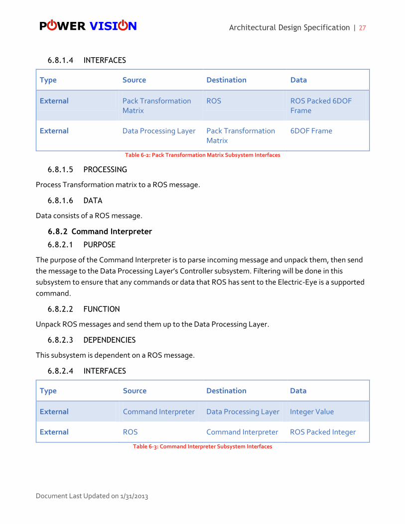
6.8.1.4 INTERFACES
Type Source Destination Data
External Pack Transformation Matrix
ROS ROS Packed 6DOF Frame
External Data Processing Layer Pack Transformation Matrix
6DOF Frame
Table 6-2: Pack Transformation Matrix Subsystem Interfaces
6.8.1.5 PROCESSING
Process Transformation matrix to a ROS message.
6.8.1.6 DATA
Data consists of a ROS message.
6.8.2 Command Interpreter
6.8.2.1 PURPOSE
The purpose of the Command Interpreter is to parse incoming message and unpack them, then send
the message to the Data Processing Layer’s Controller subsystem. Filtering will be done in this
subsystem to ensure that any commands or data that ROS has sent to the Electric-Eye is a supported
command.
6.8.2.2 FUNCTION
Unpack ROS messages and send them up to the Data Processing Layer.
6.8.2.3 DEPENDENCIES
This subsystem is dependent on a ROS message.
6.8.2.4 INTERFACES
Type Source Destination Data
External Command Interpreter Data Processing Layer Integer Value
External ROS Command Interpreter ROS Packed Integer
Table 6-3: Command Interpreter Subsystem Interfaces

Architectural Design Specification | 28
Document Last Updated on 1/31/2013
6.8.2.5 PROCESSING
Process messages from ROS.
6.8.2.6 DATA
ROS message
Architectural Design Specification | 29
Document Last Updated on 1/31/2013
7. Operating System Dependencies
7.1 Overview
Each layer will be developed in C++ with a Linux-based PC. The executable file will be transferred to
the Electric-Eye module that will also run a Linux-based operating system.
7.2 I/O Interface Layer
The I/O Interface Layer will be dependent on PCL libraries at runtime. The Linux operating system will
utilize these Point-Cloud libraries and the drivers provided by OpenNI to read in frames from the RGB-
D camera during runtime. This layer will also utilize the CUDA GPGPU framework which is required by
PCL to operate properly. The CUDA framework allows the GPU on the NVIDIA graphics card to work
in parallel with the CPU on the motherboard, thus allowing faster and more efficient processing when
reading in frames. Additional services needed by the Linux operating system include: running the
program at startup and handling input from the number pad switch.
7.3 Data Processing Layer
The Data Processing Layer will utilize Point-Cloud and boost libraries at runtime. The Linux operating
system will provide services in this layer that monitor the system’s memory and hard drive usage. This
layer will also store and retrieve PCL frames which will require the Linux operating system to perform
the appropriate actions.
7.4 Communication Layer
The Communication Layer will utilize the Linux operating system networking stack to establish a
connection to the ROS node via Ethernet. There will be no dependencies on any Point-Cloud or boost
libraries in this layer.

Architectural Design Specification | 30
Document Last Updated on 1/31/2013
8. Inter-Subsystem Data Flow
Figure 8-1: Inter-Subsystem Data Flow
Architectural Design Specification | 31
Document Last Updated on 1/31/2013
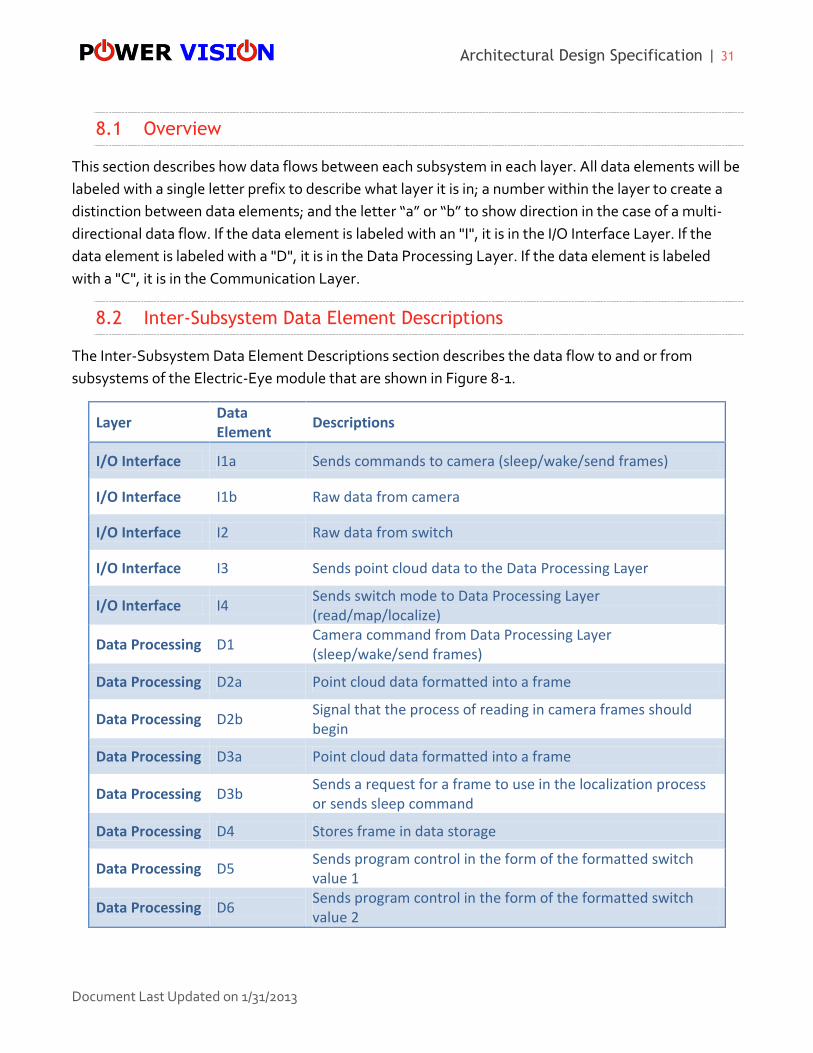
8.1 Overview
This section describes how data flows between each subsystem in each layer. All data elements will be
labeled with a single letter prefix to describe what layer it is in; a number within the layer to create a
distinction between data elements; and the letter “a” or “b” to show direction in the case of a multi-
directional data flow. If the data element is labeled with an "I", it is in the I/O Interface Layer. If the
data element is labeled with a "D", it is in the Data Processing Layer. If the data element is labeled
with a "C", it is in the Communication Layer.
8.2 Inter-Subsystem Data Element Descriptions
The Inter-Subsystem Data Element Descriptions section describes the data flow to and or from
subsystems of the Electric-Eye module that are shown in Figure 8-1.
Layer Data Element
Descriptions
I/O Interface I1a Sends commands to camera (sleep/wake/send frames)
I/O Interface I1b Raw data from camera
I/O Interface I2 Raw data from switch
I/O Interface I3 Sends point cloud data to the Data Processing Layer
I/O Interface I4 Sends switch mode to Data Processing Layer (read/map/localize)
Data Processing D1 Camera command from Data Processing Layer (sleep/wake/send frames)
Data Processing D2a Point cloud data formatted into a frame
Data Processing D2b Signal that the process of reading in camera frames should begin
Data Processing D3a Point cloud data formatted into a frame
Data Processing D3b Sends a request for a frame to use in the localization process or sends sleep command
Data Processing D4 Stores frame in data storage
Data Processing D5 Sends program control in the form of the formatted switch value 1
Data Processing D6 Sends program control in the form of the formatted switch value 2

Architectural Design Specification | 32
Document Last Updated on 1/31/2013
Data Processing D7 Sends program control in the form of the formatted switch value 3 or the sleep command value 4 for wake up or 5 to go to sleep
Data Processing D8a Sends either a frame back to the data storage when finished with it in the mapping process or the finished map
Data Processing D8b Retrieves a frame for the mapping process
Data Processing D9a Sends back the map for storage when done using it for localizing
Data Processing D9b Retrieves the map for the localization process
Data Processing D10 Sends transformation matrix to Communication Layer
Communication C1 Interpreted ROS sleep message sent to Data Processing Layer
Communication C2 Packages a transformation matrix and sends it to ROS
Communication C3 Sleep command from ROS
Table 8-1: Inter-Subsystem Data Element Descriptions
8.3 Producer-Consumer Relationship
The producer is the subsystem that generates the data element. The consumer is the subsystem that
receives the data element. The interactions are shown in the intersection of the producer row and the
consumer column. The intersecting cell is labeled with the data element name given, and described, in
Table 8-1.

Architectural Design Specification | 33
Document Last Updated on 1/31/2013
Producer-Consumer Relationship
Consumer Subsystem
I/O Interface Data Processing Communication
Cam
era
RG
B-D
Cam
era
Interp
reter
Switch
Signal In
terpreter
Store Fram
es
Data Sto
rage
Cam
era H
and
ler
Co
ntro
ller
Map
pin
g
Localizatio
n
Pack Tran
sform
ation
Matrix
Co
mm
and
Interp
reter
RO
S
Pro
du
cer Su
bsystem
I/O In
terface
Camera - I1b
RGB-D Camera Interpreter
I1a - I3
Switch - I2
Signal Interpreter - I4
Data P
rocessin
g
Store Frames - D4 D2b
Data Storage - D8b D9b
Camera Handler D1 D2a - D3a
Controller D5 - D6 D7
Mapping D8a -
Localization D9a D3b - D10
Co
mm
un
ication
Pack Transformation Matrix
- C2
Command Interpreter C1 -
ROS C3 -
Table 8-2: Producer-Consumer Relationship

Architectural Design Specification | 34
Document Last Updated on 1/31/2013
9. Requirements Mapping
9.1 Overview
Requirements mapping will be used in order to ensure that all key requirements are satisfied in the
Architectural Design. The figure below displays every key requirement and which architectural layer
that it is associated with. High level requirements that are part of packaging are not included.
Requirement Number
Requirement Name
I/O Interface Layer
Data Processing Layer
Communication Layer
3.1 ROS Compatible X
3.2 Mapping X
3.3 Localization X X X
3.7 RGB-D Camera X
3.8 On-Board Storage X
8.3 Mode Switch X
Table 9-1: Requirements Mapping

Architectural Design Specification | 35
Document Last Updated on 1/31/2013
10. Testing Considerations
10.1 Overview
The system architecture will be tested by team Power Vision to verify that the Electric-Eye fulfills all of
the requirements laid out in the System Requirements Specification and this Architectural Design
Specification. Each component and subsystem is designed to work independently and this
independence allows each to be tested individually.
10.2 Testing Approach
Team Power Vision will test all of the subsystem components independently to verify correct output
before integration into the rest of the component. After all subsystems of a component are complete,
that component will be tested as a whole for correct results. This process will be repeated for each
component in the architecture.
Once all components are created, Power Vision will integrate and perform integration testing to
ensure all components still work as expected after being integrated into one system.
Team Power Vision will check to make sure all outputs are valid and the data flow is as expected by
the architecture.
10.3 I/O Interface Layer
The I/O Interface Layer must be able to gather input from the hardware devices such as the RGB-D
camera and the physical switch. Team Power Vision will ensure that this layer is receiving the signals
from the hardware correctly.
10.3.1 RGB-D Camera Interpreter
Verify that the interpreter is able to receive the output from the physical RGB-D camera and parse it
correctly.
10.3.2 Signal Interpreter
Verify that the interpreter is able to distinguish the position of the physical switch and send out the
correct output.

Architectural Design Specification | 36
Document Last Updated on 1/31/2013
10.4 Data Processing Layer
This layer must be able to parse RGB-D camera data into a useful map and localize the Electric-Eye’s
position within the map. Based on the switch’s position, this layer will either store frames, map, or
localize the Electric-Eye. It will also respond to ROS requests brought up by the Communication Layer.
10.4.1 Camera Handler
Verify that the Camera Handler is receiving the frames and sending them out to the correct
subsystem.
10.4.2 Store Frames
Verify that Store Frames is receiving frames from the Camera Handler and sending them to the hard
disk. Also verify that it responds to activation and shutdown from the Controller subsystem.
10.4.3 Mapping
Verify that the Mapping subsystem is pulling frames from the hard disk and is converting them to a 3-
D map, and storing that map back to the hard disk. Power Vision will also verify that the Mapping
subsystem also responds to activation and shutdown from the Controller subsystem.
10.4.4 Localization
Verify that Localization is pulling the map from the hard disk, using the map to localize the Electric-
Eye, and sending the transformation matrix to the Communication Layer. Power Vision will also verify
that the Localization subsystem is responding to activation and shutdown from the Controller
subsystem.
10.4.5 Controller
Verify the controller is receiving the switch position from the Signal Interpreter and is activating and
shutting down the corresponding subsystem.
10.5 Communication Layer
This layer must be able to pack and unpack messages to and from ROS, passing them on to the Data
Processing Layer or sending them out of the module.
10.5.1 Pack Transformation Matrix
Verify that the Pack Transformation Matrix subsystem can receive the transformation matrix from the
Data Processing Layer and send it out as a ROS message out of the module.

Architectural Design Specification | 37
Document Last Updated on 1/31/2013
10.5.2 Command Interpreter
Verify that the Command Interpreter can receive ROS packets, unpack them and send the command
up to the Data Processing Layer.
Architectural Design Specification | 38
Document Last Updated on 1/31/2013
11. Glossary
11.1 Robot Operating System (ROS)
The Robot Operating System, or ROS, is an operating system that can be installed on top of Linux or
Microsoft Windows. This operating system provides libraries and tools to help software developers
create robot applications. Some of the features that ROS offers are hardware abstraction, device
drivers, message-passing and more. More information about ROS can be found at: www.ros.org
11.2 Point Cloud Library (PCL)
Point Cloud Library, or PCL, is a large scale open project for 2D/3D image and point cloud processing.
PCL contains many algorithms that are useful for 3D image processing such as noise filtering. PCL is
open source software that is free for commercial and research use. More information about PCL can
be found at: www.pointclouds.org
11.3 Transformation Matrix (6DOF)
The transformation matrix, or 6DOF, is a term used throughout the document. The transformation
matrix is a set of data that will be sent to ROS from the Electric-Eye which will include the pitch, roll,
yaw, x, y, and z data of the current location that the robot is located in respect to the camera.
11.4 RGB-D Camera
A special camera that reads frames like a normal camera but can represent the depth of the image
using color. (Red means near while blue means far). Thus this type of camera can be very useful in
helping robot navigate. More information can be found at:
http://www.hizook.com/blog/2010/03/28/low-cost-depth-cameras-aka-ranging-cameras-or-rgb-d-
cameras-emerge-2010
11.5 OpenNI
OpenNI is an open source software development kit used for the development of 3D sensing libraries
and applications. More information can be found at: http://www.openni.org/
Architectural Design Specification | 39
Document Last Updated on 1/31/2013
11.6 Point Cloud
Point Cloud is a set of vertices in 3D space that include x, y, and z coordinates. It is used by 3D sensing
cameras to capture and store 3D images. More information can be found at:
http://en.wikipedia.org/wiki/Point_cloud
11.7 Point Cloud Frame
A camera screen shot that holds point cloud data of an area.
11.8 Mapping
Mapping is the process of collecting data of one’s environment and using it to construct a type of map
that can be used for localization. More information can be found at:
http://en.wikipedia.org/wiki/Robot_localization
11.9 Localization
Localization is the process of determining one’s position and direction in a given environment. More
information can be found at: http://en.wikipedia.org/wiki/Navigation
11.10 ROS Node
A node is processes that are used to help control robot functionality by communicating with other
nodes. More information can be found at: http://www.ros.org/wiki/Nodes