architecture design in verilog hdl -...
TRANSCRIPT
OASIS NoC Architecture Design
in Verilog HDL Technical Report: TR-062010-OASIS
Written by
Kenichi Mori
ASL-Ben Abdallah Group
Graduate School of Computer Science and Engineering
The University of Aizu
2010/6/4 1 OASIS NoC Architecture
Outline
2010/6/4 2
• Network-on-Chip OASIS NoC Overview
• Hardware Design Detail
– Network design
– A router design
– Input port design • Buffering, and routing mechanism
– Arbiter design • Scheduling, and Stall/Go flow control mechanism
– Crossbar design • Transmission mechanism
• Design tools and Results
• Conclusion OASIS NoC Architecture
Network-on-Chip configurations
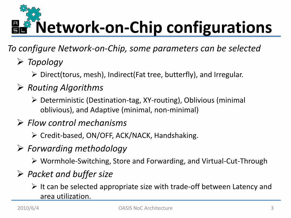
Topology Direct(torus, mesh), Indirect(Fat tree, butterfly), and Irregular.
Routing Algorithms Deterministic (Destination-tag, XY-routing), Oblivious (minimal
oblivious), and Adaptive (minimal, non-minimal)
Flow control mechanisms Credit-based, ON/OFF, ACK/NACK, Handshaking.
Forwarding methodology Wormhole-Switching, Store and Forwarding, and Virtual-Cut-Through
Packet and buffer size It can be selected appropriate size with trade-off between Latency and
area utilization.
2010/6/4 3
To configure Network-on-Chip, some parameters can be selected
OASIS NoC Architecture
Design Level
2010/6/4 4
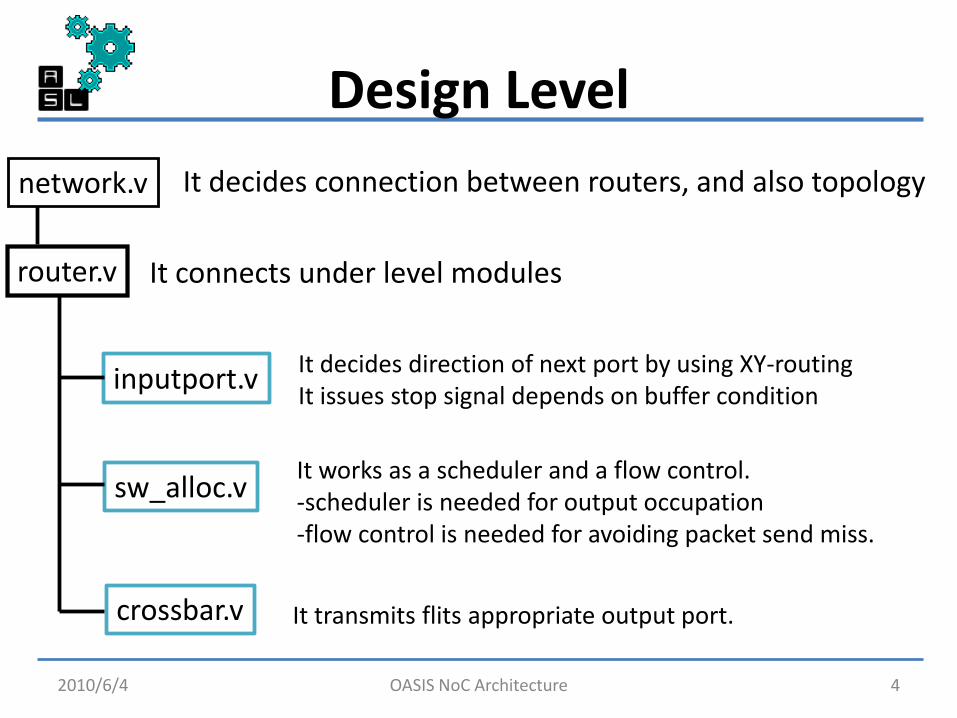
network.v
router.v
It decides connection between routers, and also topology
It connects under level modules
inputport.v It decides direction of next port by using XY-routing It issues stop signal depends on buffer condition
sw_alloc.v It works as a scheduler and a flow control. -scheduler is needed for output occupation -flow control is needed for avoiding packet send miss.
crossbar.v It transmits flits appropriate output port.
OASIS NoC Architecture
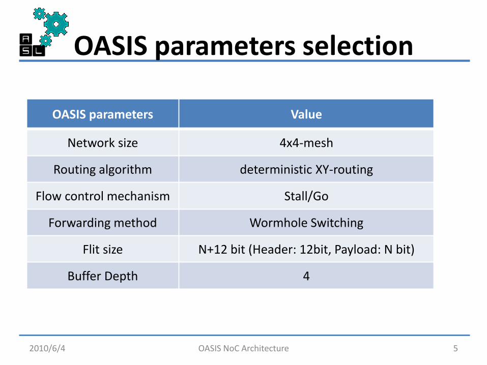
OASIS parameters selection
2010/6/4 5
OASIS parameters Value
Network size 4x4-mesh
Routing algorithm deterministic XY-routing
Flow control mechanism Stall/Go
Forwarding method Wormhole Switching
Flit size N+12 bit (Header: 12bit, Payload: N bit)
Buffer Depth 4
OASIS NoC Architecture

Network (1/2)
2010/6/4 OASIS NoC Architecture 6
Arbiter
Arbiter Arbiter
Arbiter
router.v router.v
router.v router.v
4x4 network size Total data input size is declared.
Control wire and data wire are separated.
network.v
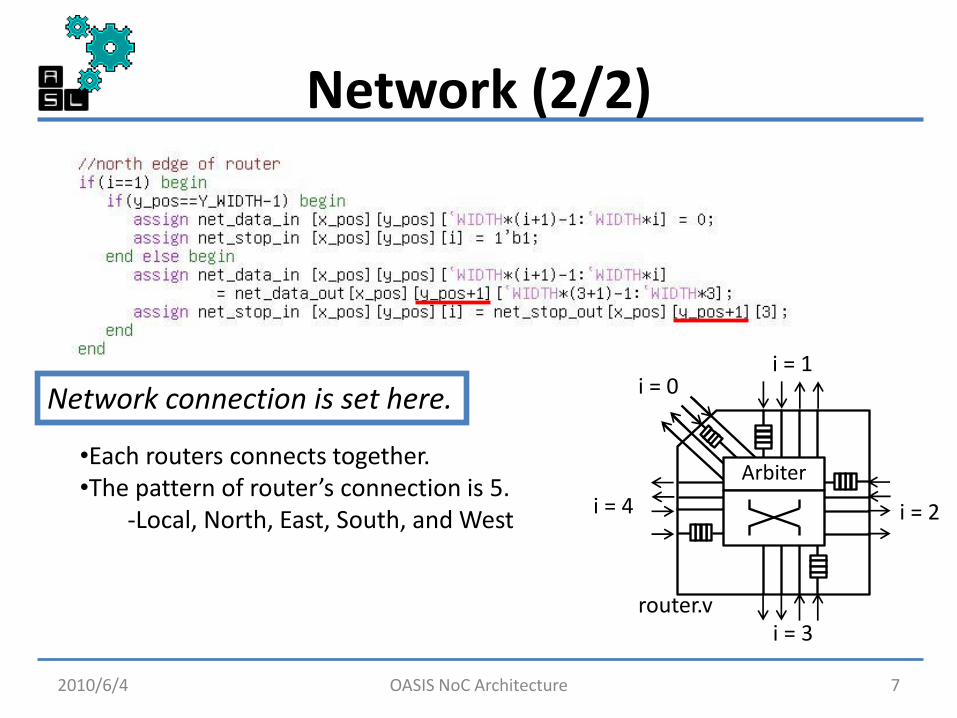
Network (2/2)
2010/6/4 7
Network connection is set here.
•Each routers connects together. •The pattern of router’s connection is 5.
-Local, North, East, South, and West
Arbiter
router.v
i = 0 i = 1
i = 2
i = 3
i = 4
OASIS NoC Architecture
Outline
2010/6/4 8
• Network-on-Chip OASIS NoC Overview
• Hardware Design Detail
– Network design
– A router design
– Input port design • Buffering, and routing mechanism
– Arbiter design • Scheduling, and Stall/Go flow control mechanism
– Crossbar design • Transmission mechanism
• Design tools and Results
• Conclusion OASIS NoC Architecture
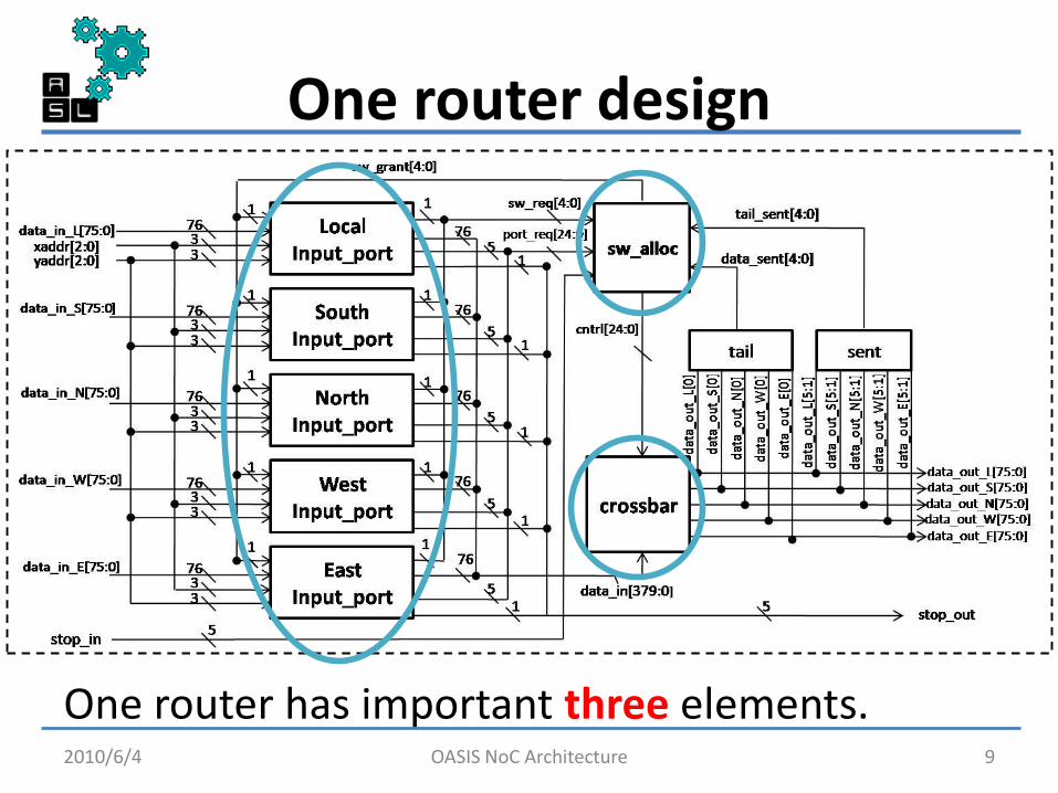
One router design
One router has important three elements. 2010/6/4 9 OASIS NoC Architecture
One router design
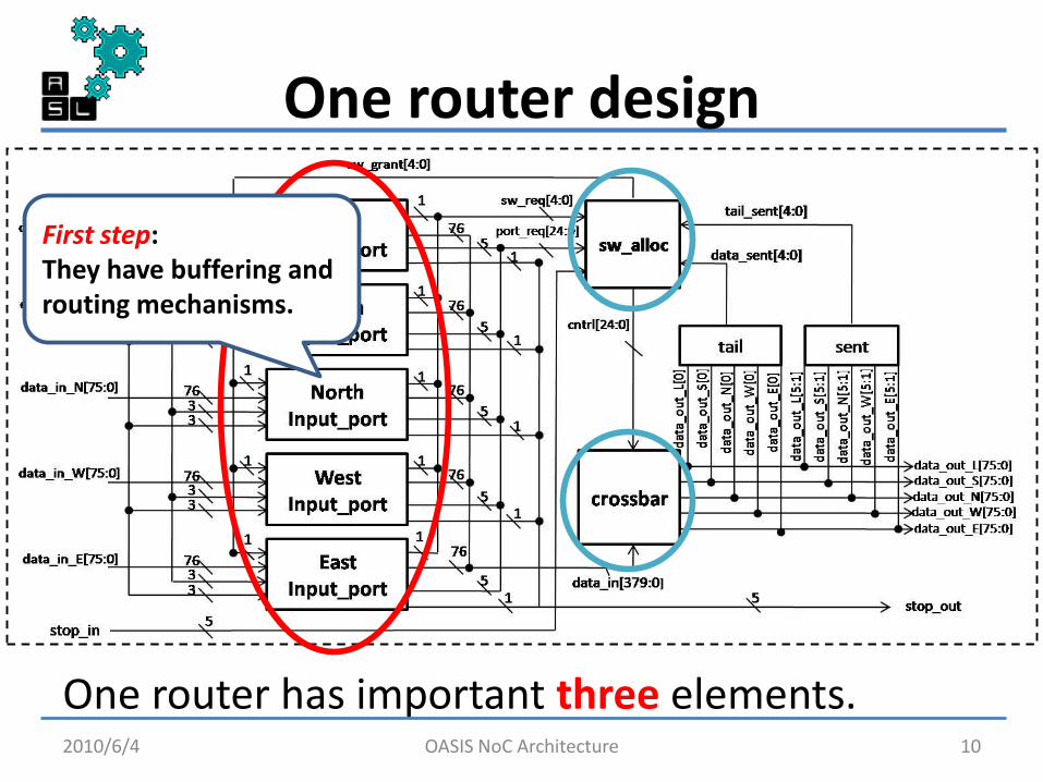
One router has important three elements. 2010/6/4 10
First step: They have buffering and routing mechanisms.
OASIS NoC Architecture

One router design
One router has important three elements. 2010/6/4 11
Second step: It has scheduling and flow control mechanism
First step: They have buffering and routing mechanisms.
OASIS NoC Architecture

One router design
One router has important three elements. 2010/6/4 12
Third step: It sends flits each adequate next port
Second step: It has scheduling and flow control mechanism
First step: They have buffering and routing mechanisms.
OASIS NoC Architecture

Input port design(fifo)
2010/6/4 13
route.v
fifo.v It has fifo and routing modules
•fifo.v -It has pointers for queue systems -It makes stop signal for flow control
head tail
OASIS NoC Architecture
Input port design(routing)
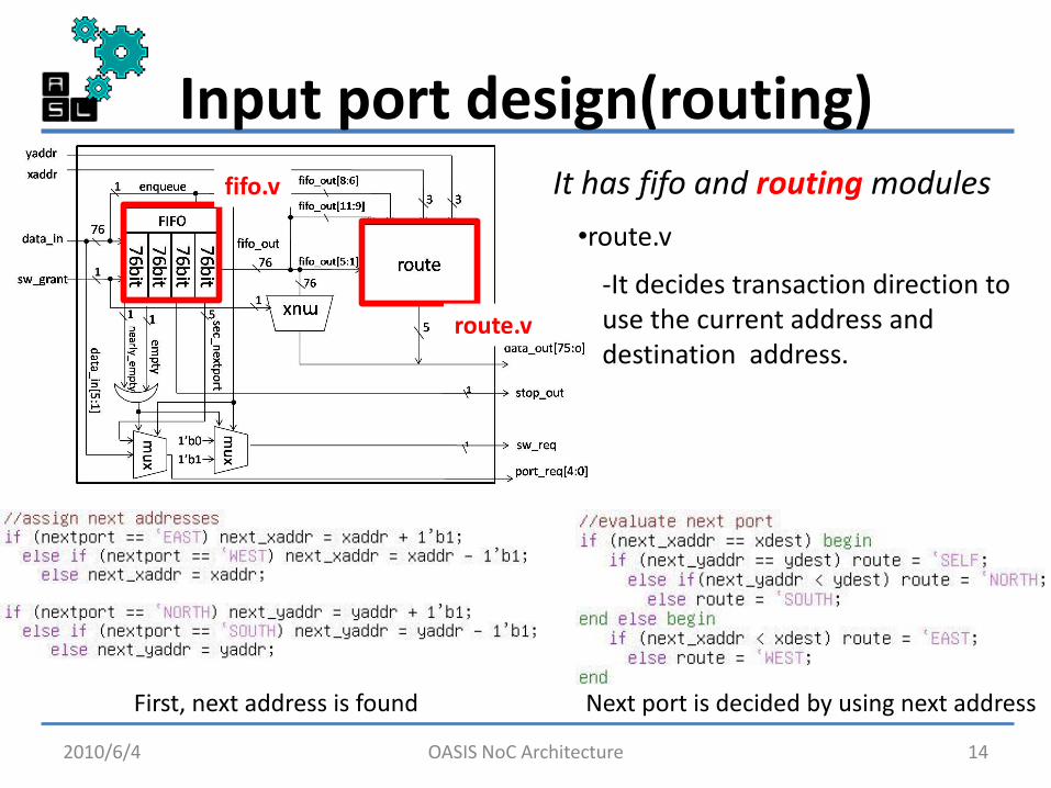
2010/6/4 14
route.v
fifo.v It has fifo and routing modules
•route.v
-It decides transaction direction to use the current address and destination address.
First, next address is found Next port is decided by using next address
OASIS NoC Architecture
Outline
2010/6/4 15
• Network-on-Chip OASIS NoC Overview
• Hardware Design Detail
– Network design
– A router design
– Input port design • Buffering, and routing mechanism
– Arbiter design • Scheduling, and Stall/Go flow control mechanism
– Crossbar design • Transmission mechanism
• Design tools and Results
• Conclusion OASIS NoC Architecture

Why scheduling is needed?
2010/6/4 16
payload
Input port _ L
Input port _ S
Input port _ N
Input port _ W
Input port _ E
arbiter req
grant
Output bandwidth is limited for one flit data size.
Scheduling is needed OASIS NoC supports Round-Robin scheduling.
OASIS NoC transmits one flit at one clock fo
These input ports want to transmit to same port.
con
trol
OASIS NoC Architecture

Arbiter design(scheduling)
2010/6/4 17
Stall_Go.v
matrix_arb_formultistage.v
-Right code indicates comparison of priority between current transmitting input port and other routers which send request to arbiter.
OASIS NoC Architecture
Arbiter design(flow control)
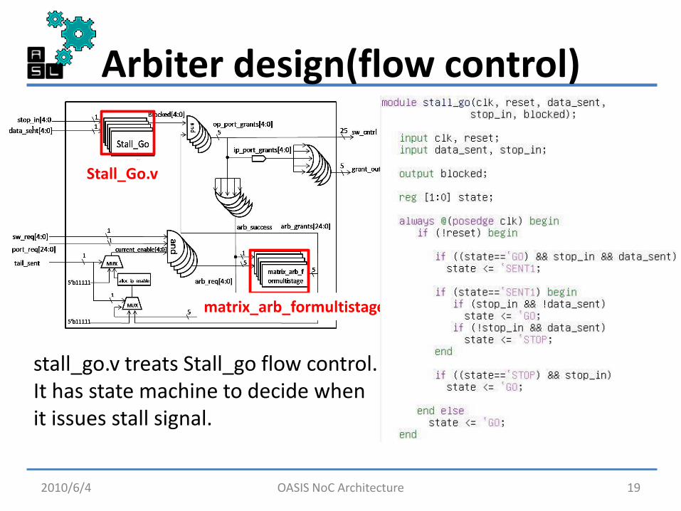
2010/6/4 19
Stall_Go.v
matrix_arb_formultistage.v
stall_go.v treats Stall_go flow control. It has state machine to decide when it issues stall signal.
OASIS NoC Architecture

Outline
2010/6/4 20
• Network-on-Chip OASIS NoC Overview
• Hardware Design Detail
– Network design
– A router design
– Input port design • Buffering, and routing mechanism
– Arbiter design • Scheduling, and Stall/Go flow control mechanism
– Crossbar design • Transmission mechanism
• Design tools and Results
• Conclusion OASIS NoC Architecture

Crossbar design
2010/6/4 21
L:0 S:0 N:0 W:1 E:0
flit flit
flit
flit
flit
It transmits flits to neighbor routers. -cntrl signal indicates which direction is destination.
mux_out.v
crossbar.v cntrl whole data
OASIS NoC Architecture
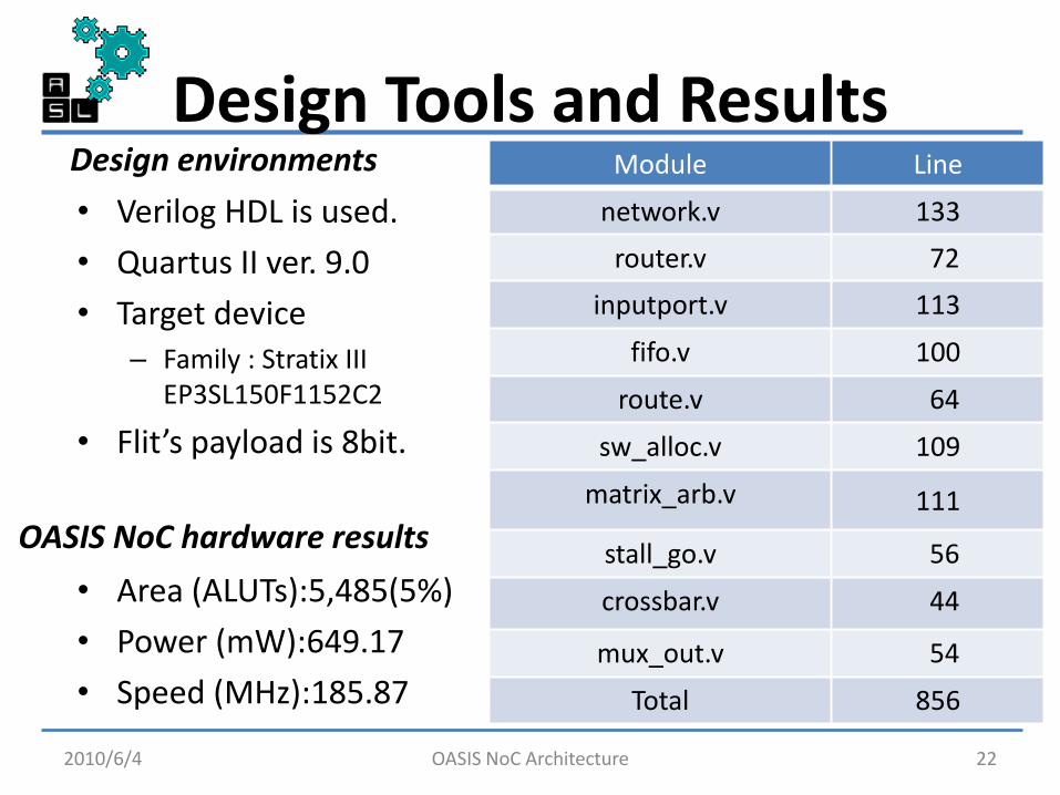
Design Tools and Results
• Verilog HDL is used.
• Quartus II ver. 9.0
• Target device – Family : Stratix III
EP3SL150F1152C2
• Flit’s payload is 8bit.
2010/6/4 22
Module Line
network.v 133
router.v 72
inputport.v 113
fifo.v 100
route.v 64
sw_alloc.v 109
matrix_arb.v 111
stall_go.v 56
crossbar.v 44
mux_out.v 54
Total 856
• Area (ALUTs):5,485(5%)
• Power (mW):649.17
• Speed (MHz):185.87
OASIS NoC hardware results
Design environments
OASIS NoC Architecture